

Italian Products
100x100 cm base Cold
and Freezer Rooms
MINICELLA100
TN / BT
INSTALLATION AND
OPERATION GUIDE
SMALL COLD-ROOMS
Cod. LINMCEL-IT-EN_REV_01_2014_M05
10.06.2014
EN
26
EN
Welcome
The producer thanks you for choosing one of its products.
We kindly ask you to read carefully our manual: this will guarantee the optimal
use of your appliance.
ITALIANO
RAEE - Gestione rifi uti apparecchiature elettriche ed elettroniche
Il simbolo del bidone barrato posto sul prodotto o sulla documentazione del manuale d’uso, indica che il prodotto è stato immesso nel
mercato dopo la data del 13 agosto 2005. Al termine del ciclo di vita utile, il prodotto, deve essere raccolto, smaltito, trasportato in
modo separato rispetto agli altri rifi uti urbani seguendo le normative vigenti in ogni paese. In questo modo potrà essere recuperato
contribuendo ad evitare possibili effetti negativi sull’ambiente e sulla salute, favorendo il reimpiego e/o il riciclo dei materiali di cui
è composta l’apparecchiatura. Lo smaltimento abusivo del prodotto da parte dell’utente comporta l’applicazione di sanzioni amministratiuve previste dalla norma vigente. La Direttiva comunitaria RAEE N° 2002/96/CE, (in Italia recepita con il Dgls del 15.05.2005
N°151); Direttiva comunitaria N°2003/108/CE riguardante il trattamento dei rifi uiti delle apparecchiature elettriche ed elettroniche.
ENGLISH
RAEE - Electrical and Electronic Waste Management)
The barred can symbol displayed on the product or in the use manual documentation indicates that the product has been placed for sale
on the market after August 13, 2005. At the end of its useful life-cycle, the product must be collected, disposed of, and transported separately from urban waste, in accordance to the norms in force in each individual country. In this way, it can be recovered, contributing
to avoid possible negative effects on the environment and health, and favoring the re-use and/or recycling of the materials of which the
equipment is made of. The abusive disposal of the product by the user entails the application of administrative sanctions established by
the norms in force. The EU Directive RAEE N. 2002/96/CE, (implemented in Italy by the Law Decree n. 151 dated May 15, 2005); EU
Directive N. 2003/108/CE concerning the handling of electrical and electronic waste.
FRANCAIS
RAEE - Gestion des déchets d’appareillages électriques et électroniques
Le symbole de la poubelle barrée placé sur le produit ou sur la documentation du manuel d’utilisation, indique que le produit a été mis
sur le marché après la date du 13 août 2005. A la fi n du cycle de vie utile, le produit doit être trié, éliminé, transporté de façon séparée
par rapport aux autres déchets urbains en suivant les normatives en vigueur dans chaque pays. De cette façon, il pourra être récupéré
en contribuant à éviter d’éventuels effets négatifs sur l’environnement et sur la santé, en favorisant le réemploi et/ou le recyclage des
matériaux dont est composé l’appareillage. L’élimination abusive du produit de la par t de l’utilisateur comporte l’application de sanctions administratives prévues par la normative en vigueur. La Directive communautaire RAEE N° 2002/96/CE, (en Italie défi nie dans
le D. lég. du 15.05.2005 n°151); Directive communautaire N° 2003/108/CE concernant le traitement des déchets des appareillages
électriques et électroniques.
DEUTSCH
RAEE - Umgang mit Abfällen elektrischer und elektronischer Geräte
Das Symbol der durchkreuzten Mülltonne auf dem Produkt oder der Dokumentation der Gebrauchsanweisung gibt an, dass das Produkt nach
dem 13. August 2005 auf den Markt gebracht wurde. Am Ende des Nutzungszyklus muss das Produkt entsprechend der im jeweiligen Land
geltenden Bestimmungen gesammelt, entsorgt und getrennt von anderem Hausmüll transportiert werden. Auf diese Weise kann es zurückgewonnen werden, wodurch zur Vermeidung möglicher negativer Auswirkungen auf die Umwelt und die Gesundheit beigetragen sowie die Wiederverwertung und das Recycling der Materialien erleichter t wird, aus denen das Gerät besteht. Die widerrechtliche Entsorgung des Produktes
durch den Nutzer zieht die Anwendung der von den gültigen Bestimmungen vorgesehenen V erwaltungsstrafen nach sich. Die gemeinschaftliche
Richtlinie RAEE Nr . 2002/96/EG, (in Italien mit der Gesetzesverordnung Nr. 151 vom 15.05.2005 umgesetzt); Gemeinschaftliche Richtlinie Nr.
2003/108/CE bezüglich der Behandlung von Abfällen elektrischer und elektronischer Geräte.
ESPANOL
RAEE - Gestión de los residuos de aparatos eléctricos y electrónicos
El símbolo del bidón barrado en el producto o en la documentación del manual de utilización, indica que el producto, ha sido introducido en el mercado después de la fecha 13 de Agosto del 2005. Al final de su ciclo de vida, el producto debe ser recogido, eliminado
y transportado de forma separada respecto a los otros residuos urbanos, siguiendo la normativa vigente en cada país. De este modo
podrá ser recuperado contribuyendo a evitar posibles efectos negativos en el medio ambiente y en la salud, favoreciendo así la reutilización y/o el reciclaje de los materiales que componen el aparato. La eliminación ilegal del producto por parte del usuario, supone la
aplicación de sanciones administrativas previstas en la normativa vigente La Directiva comunitaria RAEE N° 2002/96/CE, (en Italia se
acoge al Decreto Legislativo del 15.05.2005 nº.151); Directiva comunitaria N° 2003/108/CE respecto al tratamiento de los residuos
de los aparatos eléctricos y electrónicos.
PORTUGUÊS
RAEE - Resíduos de Equipamentos Eléctricos e Electrónicos
O símbolo do contentor de lixo barrado com uma cruz, aposto no produto ou no manual de utilização, indica que o produto foi colocado no mercado a partir de 13 de Agosto de 2005 e que, no fi m do seu ciclo de vida, deve ser recolhido, eliminado e transportado
de modo separado respeito aos outros resíduos urbanos e em conformidade com as normativas vigentes em cada país de utilização.
Agindo dessa maneira estará contribuindo para evitar possíveis efeitos negativos no ambiente e na saúde, favorecendo a reutilização
e/ou reciclagem dos materiais de que é composta a aparelhagem. Uma eliminação incorrecta e abusiva do produto por parte do utilizador implicará a aplicação das sanções administrativas previstas pela normativa vigente. Directiva comunitária RAEE N°2002/96/
CE, em Itália acolhida pelo D.L. nº 151 de 15 de Maio de 2005, e Directiva comunitária N°2003/108/CE, relativas ao tratamento dos
resíduos de equipamentos eléctricos e electrónicos.
RAEE
WEEE
RAEE
WEEE
RAEE
WEEE
RAEE
WEEE
RAEE
WEEE
RAEE
WEEE

27
EN
INDEX
INTRODUCTION pag. 28
USING MANUAL pag. 28
MANUAL PRESERVATION pag. 28
MINI COLD-ROOM DESCRIPTION pag. 29
1. MINI COLD-ROOM POSITIONING pag. 30
1.1 TRANSPORTATION pag. 30
1.2 DOWNLOAD - UNLOAD / LENGTHS / WEIGHTS pag. 30
1.3 PACKING pag. 30
1.4 CONDENSATE WATER DRAINING/ DRAINING CONNECTION pag. 30
1.5 INSTALLATION INSIDE YOUR SHOP/RESTAURANT /WORKROOM pag. 31
1.6 WALL MINIMUM DISTANCE pag. 31
1.7 MINI COLD-ROOM WITH BUIlT- IN UNIT pag. 31
1.8 MINI COLD-ROOM WITH REMOTE CONDENSING UNIT VERSION pag. 32
2.
ELECTRICAL CONNECTION AND EARTHING
pag. 32
2.1 ELECTRICAL POWER SUPPLY pag. 32
2.2 START UP AND USE pag. 33
3. CLEANING pag. 33
3.1 MINI COLD-ROOM CLEANING pag. 33
3.2 CONDENSER’S BUIlT-IN UNIT CLEANING pag. 34
3.3 FLOOR CLEANING pag. 34
4. GENERAL GUIDELINES pag. 35
4.1 MAX SHELF LOAD pag. 35
4.2 STORING PRODUCTS pag. 35
4.3 DEFROSTING pag. 36
5. MAINTENANCE - WASTE MANAGEMENT - DISPOSAL OF MATERIALS
pag. 36
5.1 PERIODICAL CHECK pag. 36
5.2 REPLACEMENT OF THE LIGHT pag. 36
5.3 SUBSTITUTION OF THE FAN MOTOR pag. 36
5.4 SUBSTITUTION OF THE COMPRESSOR/ Refrigerated gas pag. 37
5.5 CONDENSER’S BUIlT-IN UNIT CLEANING pag. 37
5.6 MINI Cold-Room WITH ELECTRIC DEFROSTING pag. 37
5.7 GARBAGE DISPOSAL pag. 37
5.8. REQUESTING SPARE PARTS pag. 37
6.
INSTRUCTION FOR THE MOUNTING OF THE MINICOLD AND MINIFREEZER ROOM
pag. 38
7. CONTROL PANEL pag. 40
DECLARATION OF CONFORMITY at the end of the manual
APPENDIX - 1 - Product identification plate at the end of the manual
APPENDIX - 2 - MINI Cold-Room parts description at the end of the manual
APPENDIX - 3 - Versions at the end of the manual
APPENDIX - 4 - Dimensions and weights at the end of the manual
APPENDIX - 5 - Dielectric test at the end of the manual
APPENDIX - 6 - Summary of electrical diagram MINI Cold-Room at the end of the manual

28
EN
INTRODUCTION
The “MINI COLD-ROOM” has been constructed in respect of the overall community norms concerning the
free circulation of industrial and commercial products in EU countries
Directive 2004/108/CE - Electromagnetic Compatibility
Directive 2006/95/CE - Low Voltage
Directive 2002/95/EC - RoHS
Before proceeding with all the operations on the products, it is recommendable to read carefully the user’s manual
and maintenance. In addition, it is important to follow all the current regulations (loading-unloading, installation of the
product, electrical connections, positioning of the item, disposal of material).
Therefore, the units are supplied with all the documentation imposed by such standards.
The company will not be held liable for any breakage, accidents or faults due to non-compliance, including non-compliance for not following the instructions of this manual. Moreover, the
company will not be responsible if the user makes any modifi cations, variants or if non-authori-
sed accessories are installed in the unit.
The maintenance requests easy operations, which can be carried out exclusively by specialized
technician.
USING MANUAL
The user and maintenance manual constitutes an integral part of the MINI Cold-Room. It
must be kept intact and in the safe place for the entire life of the appliance, even if the
appliance is transferred to another user or owner. The manual must be easily consulted by opera-
tors and maintenance staff and must be placed nearby the unit.
The appliance includes all documentation required by regulations in force, which are reached during the planning
and manufacturing phase. All the instructions prescribed on this manual must help the operator and the qualifi ed
technician to conduct all installation procedures, connections, use and maintenance of the system, in a safely
manner and correctly. This user and maintenance manual contains all the information required for handling the
unit with particular attention to safety.
MANUAL PRESERVATION
It is advisable to use the manual with care and in such a way as not to compromise its
contents.
Under no circumstances shall the user remove, pull out or rewrite any parts of the manual.
Keep the manual in a place protected against humidity and heat. The instruction manual shall
be kept nearby the unit so that operators can easily consult the manual. The manual must also return to its
location after each consultation. Furthermore, the manual must be kept for the entire life of the appliance and
must be handed over to any successive user or owner.
THE MANUFACTURER RESERVES THE RIGHT TO MAKE TECHNICAL MODIFICATIONS

29
EN
TO ITS OWN PRODUCTS WITHOUT GIVING PRIOR NOTICE.
MINI COLD-ROOM DESCRIPTION
The Mini Cold-Room assures the stability and do not deteriorate on the time. The materials composed the
cold-room are made do not absorb smell an do not agree the formation of the parasitics, the mushroom and
mould. The cold-rooms are composed with modular panels with different width mm 1000 with thickness mm
60 The fi xed panels is done from the internal part of the cold-room by the eccentric hooks. The fl oor and ceiling
panels are positioned to the internal side of the vertical panels and around of perimetral side, is applied a plastic
sanitary profi le. The characteristics of the cold-rooms are showed below.
Wall - ceiling - fl oor cover panels
The wall panel is made with two atoxic prepainted stainless steel zinc plates appproved by Igiene Institute. The
fl oor panel is made externally with stainless steel zinc plate and internally with stainless steel AISI 304 inox
operating antiskid.
Cold-room temperature:
Normal temperature NT: 0 / +8°C
Low temperature LT: -18 / -20°C
Isolamento:
The insulation is made with polyurethane injection (PUR) with characteristics as follow:
Panel thickness : 60 mm
K (Kcal /h m2 °C): 0,26
Density: 40-42 kg/mc
The insulation of the basin is free of CFC in order to guarantee a low environmental impact.
The Mini Cold-Room is available as follow:
• already assembled or not assembly.
• On pallet and nylon covering if the cold-room is deliveried already mounted.
• Walls and fl oor panels thickness mm 60 available to introducing trolley trays with soft wheels
• Door with magnetic closimg gasket 700 x 1680 H mm
• Stainless steel grids 400 x 870 mm
• Monoblockrefrigerating in R404A/R507 available for TN / BT version including with electronic control
panel Positioning on the roof of the small cold-room.
External sizes small cold-room
• Included monoblock 1000 x 1000 x 2300 H mm
• Without monoblock 1000 x 1000 x 1800 H mm
ATTENTION
All operations regarding the points:
1. MINI Cold-Room POSITIONING - 2. ELECTRICAL POWER SUPPLY AND CONNECTIONS - 3. CLEANING - 5.
MAINTENANCE
must be carried out by high qualifi ed technical staff.
30
EN
1. MINI COLD-ROOM POSITIONING
Before to unload/download and positioning the MINI Cold-Room inside the sale-area, please read
with attention this instruction manual so the sections regarding unload/download of the MINI ColdRoom, length, weight, water pipe drain position and electronic control panel settings.
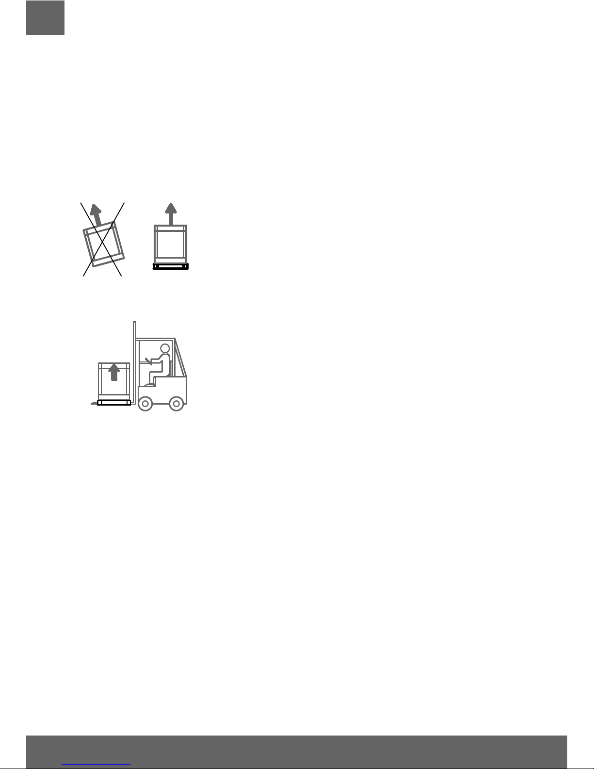
1.1 TRANSPORTATION
Kg
Kg
NO SI
Do not superimpose
MINI Cold-Room
packing (allowed only if there
is wooden crate packing option).
We recommend you to transport the
MINI Cold-Room
always in the upright position (as mention on the packing). If the MINI Cold-Room with built in condensing
unit was inclined during transportation we suggest you to keep the product in
the suggested upright position for at least 8 hours, before switching it on. In this
way, you will allow the oil to fl ow in all the components, lubricating them again.
Afterwards you can proceed with the start.
1.2 DOWNLOAD - UNLOAD / LENGTHS / WEIGHTS
Kg
The unloading/loading procedures should be executed by pallet-jack or by forklift
driven by skilled and authorized staff. We decline any liability for failing to comply
with safety rules currently in force.
Before starting the unloading, positioning and installation procedures of the MINI
Cold-Room inside the shop/kitchen according to the model of the MINI Cold-Room, please read carefully the information showed in the dimensions and weights list.
The manufacturer declines any responsibilities due to operations performed without adopting the
above safety precautions.
1.3 PACKING
At the delivery please check that the packing is intact and that during transportation no damage
was occurred. Remove the external carton-box; remove the fastener that keeps still the MINI ColdRoom to its pallet, put it in the correct position and then remove the adhesive white protection of
the stainless steel.
The recovery and the recycling of the packing materials such us, plastic, iron, carton box, wood
help the saving of row material and reduce the waste. Please consult your area address book for
disposal of materials and authorized garbage dump.
1.4 CONDENSATE WATER DRAINING/ DRAINING CONNECTION
The MINI Cold-Rooms are available as follow:
WITH BUIlT-IN UNIT:
• Monoblock unit:
MINI Cold-Room included automatic re-evaporation water drain
PREDISPOSED FOR REMOTE UNIT:
• Monoblock unit: predisposed for remote unit.
31
EN
• MINI Cold-Room predisposed for remote unit.
Both of them include water pipe drain with siphon predisposed for water drain connection ( to be
install by the
customer)
You never install the MINI Cold-Room without siphon and to connect more drains of the same MINI
Cold-Room together. Each drain must have only one siphon.
For more information please, see the APPENDIX 3 “VERSION”.
1.5 INSTALLATION INSIDE YOUR SHOP/RESTAURANT / WORKROOM
It is advisable to install the
MINI Cold-Room
inside an area with an air conditioning system. Please
note that malfunctions may arise in areas that are not provided with air conditioning, e.g. condensation formation
ATTENTION
In order to allow a good functioning of the
MINI Cold-Room
please draw attentions to the fol-
lowing instructions:
• Do not place the MINI Cold-Room to a direct exposure of sunlight and to all the other
means of irradiation, such as high intensity incandescent lights, cooking ovens, heating radiators.
• Avoid to close the air in-take of the monoblock or built-in unit.
• Do not put any material as carton or others, on the top of the MINI Cold-Room in
which is positioning the monoblock unit or the condensing unit.
• Do not positioning the MINI Cold-Room inside the area in which there is to much hu-
midity (possible making condensation of the surface of the MINI Cold-Room).
• Do not positioning the MINI Cold-Room inside a close cavity (there is no circulation of
air and the MINI Cold-Room will not run properly).
• Do not positioning two or more MINI Cold-Rooms back-to-back position (the unit will not be properly).
Verify that in the installation room there is enough air turnover, even during closing and rest hours.
In this way the expansion/condensing unit will work correctly.
1.6 WALL MINIMUM DISTANCE
In order to allow a good performance of the MINI Cold-Room, during the installation you must
respect the MINIMUM WALL distances :
not less than 5 cm all around the Cold-Room and not less than 40 cm from the momoblock, posi-
tionated on the top af the Cold-Room, to the ceiling of the room where the Cold-Room is placed.
1.7 MINI COLD-ROOM WITH BUIlT- IN UNIT
If the MINI Cold-Room is fi tted with built-in condensing unit, check if the foot board obstructs air circulation.
Do not put any cartoons or any others materials and do not close the air in-take and out-take on
all sides of the MINI Cold-Rooms.
For a good running and performance of the MINI Cold-Room, do not obstruct the condensing unit ventilation.
32
EN
All the air suction grids and air delivery grids must be always opening.
Check if the room is suffi ciently aired, even when the shop is closed. Avoid to obstruct the sources of air placing
objects along the perimeter of the MINI Cold-Room. It is necessary to place MINI Cold-Rooms at least fi ve
centimetres from the wall. Before activating electric connection clean the MINI Cold-Room completely by using
tepid water and neutral detergents (non-aggressive) . Dry it with a smooth rag.
1.8 MINI COLD-ROOM WITH REMOTE CONDENSING UNIT VERSION
The electrical and cooling connection must be done only from a qualifi ed technician.
We recommend to follow the electrical norms.
The engine of the MINI Cold-Rooms with remote refrigerating unit must be protected from atmospheric agents and the room must not be used for storing goods (free space all around the remote
unit). Respect the spaces between the unit and the walls or others obstacles, in order to have a
good air exchange to avoid a good performance and easy maintenance during the cleaning of the
condensing unit. It is necessary to remember that higher room temperature and insuffi cient air cir-
culation around the condensing unit imply higher energy costs and worse technical performances
of the refrigerator, with a possible waste of the exposed goods.
2. ELECTRICAL CONNECTION AND EARTHING
2.1 ELECTRICAL POWER SUPPLY
The installation and the electrical connections must be carried out in conformity with the electrical rules in force. These operations must be carried out by qualifi ed staff. The company declines
any responsibilities originated from the no observance of the above rules in force.
See the appliance electric diagrams at appendix – 6 at the end of this manual.
Before plugging in the MINI Cold-Room, it is necessary to proceed with its complete and
careful cleaning, using warm water with no aggressive detergents and drying with a soft
cloth all the humid parts (read with attention the chapter 3. cleaning).
In order to carry out a correct plug in you must proceed as follow:
1. Before the connection to the electrical supply it is necessary to verify that the frequency / tension of
the line correspond to those written on the identifi cation label of the MINI Cold-Room (APPENDIX
2 - IDENTIFICATION LABLE OF THE MINI Cold-Room). A variation +/- 10% of the nominal rated
voltage is permitted. It is needful to connect the appliance to an effi cient ground socket (see point 6)
2. It is advisable to install an onnipolar sectioning switch with opening of contacts at least 3 mm
wide at the source as for example automatic switch, fuse wire (the fuse screw must be removed
from the socket) switch for fault current and electricity meter.
3. In order to save the appliance from overload or short circuit, the connection to the electricity
has to be done through a magneto-thermal switch high sensibility (30 mA) with manual reestablishment, of the right power.
4. For protective device size, consider the power consumptions showed on the identifi cation label
of the appliance (APPENDIX 2 – identifi cation label product)
5. It is necessary that the connection cable section is commensurate to the power consumption of the unit.
6. The law requires that the unit is earthed; therefore it is necessary to connect it to an
effi cient earth connection. In order to prevent any risks if the electrical cable and the
compressor supplied are damaged, these must be replaced by qualifi ed technician.
Installation must be carried out only by qualifi ed technicians according to the regulation in
force. No liability whatsoever can be accepted if the above instructions in not complied with.
33
EN
WARNING
Any operation of ordinary and extraordinary maintenance of the appliance must be done disconnecting the electric power supply. This maintenance must be done by qualifi ed technician.
The plug has to be always connected to a fi xed outlet. It is strictly forbidden to connect the applian-
ce plug to an extension cord or an adapter.
2.2 START UP AND USE
WARNING
Before to proceed to the switch-ON of the MINI Cold-Room you have to verify as follow:
• don’t start the appliance with humid or wet hands
• appliance surfaces and surrounding are dry
• the MINI Cold-Room with built-in unit had been placed in vertical position, if it should be sloped, we suggest to wait at least 8 hours before to proceed with the start-up.
• the parameters regulation are referring to the use instruction of the control panel attached to the present manual.
• before connecting the plug in the socket check if the sectioning unit is in the
• position marked by “0,” “OFF”
• for remote unit MINI Cold-Room the fi rst starting has to be made by qualifi ed technicians.
After having checked as above, it is possible to start the appliance, giving electricity from the general power pack (see paragraph. 2.1). Press green button in position n. 1, ON.
WARNING
Before loading the food on the appliances, wait that the temperature needed is the same on the
control panel. Avoid to set a lower temperature than that suggested according to the category the
MINI Cold-Room belong to in order to avoid evaporator block.
To regulate functioning parameters please follow the instruction attached to the present manual.
3. CLEANING
All the procedures must be carried out with the stationary unit removing the tension from both
the refrigerated item and the condensing unit.
3.1 MINI COLD-ROOM CLEANING
The maintenance of the apliance must include at least one daily cleaning of the loading zone, in
order to prevent the development and the accumulation of bacteria.
34
EN
ATTENTION
It is essential to keep daily clean the apliance in order to prevent the development and the accumulation of bacteria. Before cleaning the chamber of the apliance, you must execute a defrosting
process, by removing the lid of the drainage basin.
Inside the upper part housing the block, it is recommended not to clean the electrical cables in
order to prevent to pull them
Do not fl ush directly the inner parts of the apliance because the electrical parts could get damaged.
• Do not use any hard metal tools to remove the ice.
• For the cleaning use only warm water (not hot) with no-aggressive detergents, taking care
of drying the wet parts with a soft cloth.
• Avoid to use products that contain chlorine or diluted solutions, caustic soda, abrasive detergents, muriatic acid, vinegar, bleach or other products that might scratch or grind.
• We recommend to clean the device at least once a month, when it used for deep-frozen products.
Attention, during the cleaning operations it is recommended to use work gloves.
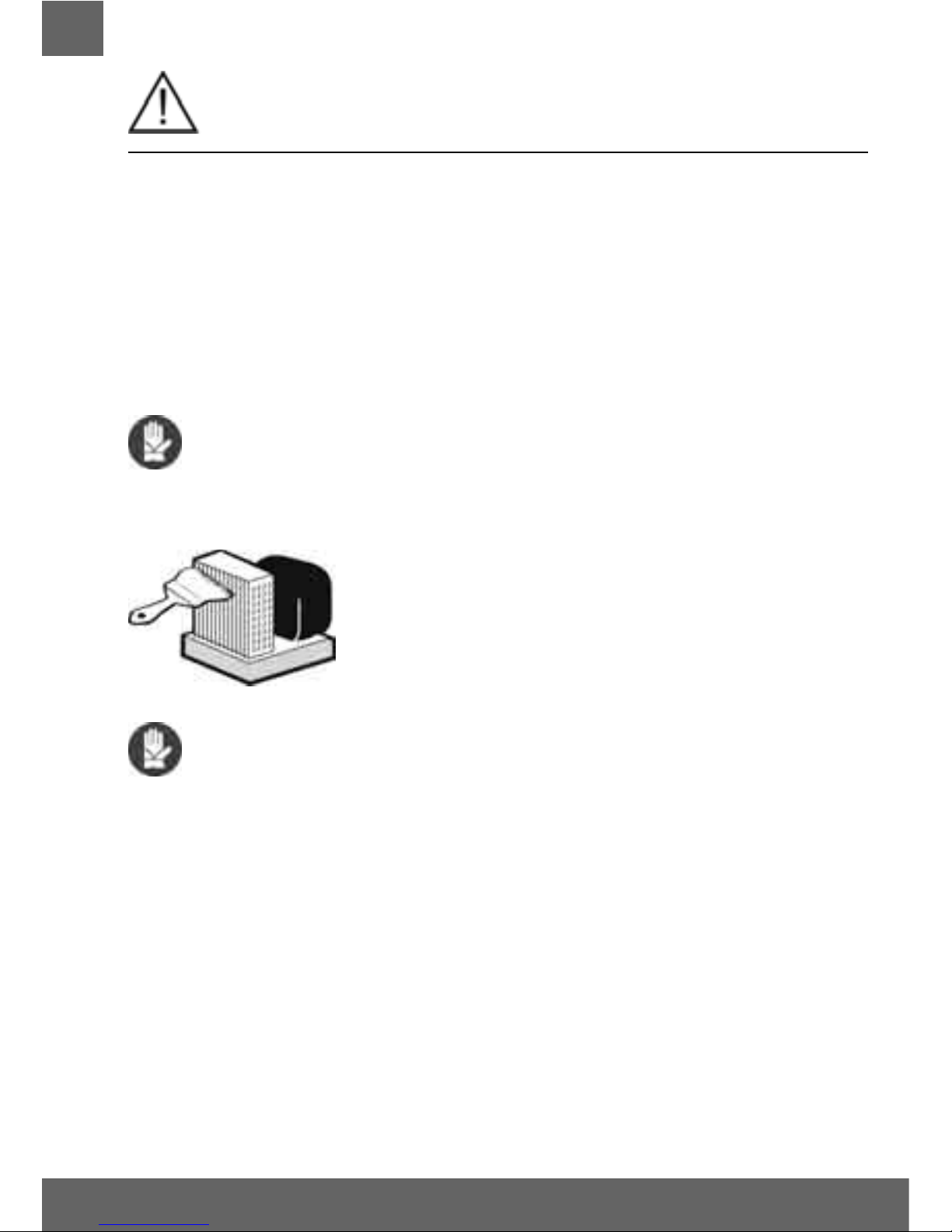
3.2 CONDENSER’S BUIlT-IN UNIT CLEANING
Any operation of cleaning must be done disconnecting the
electric power supply.
The condenser of the MINI Cold-Room with built-in unit must be cleaned, in
normal conditions of use of the MINI Cold-Room, at least once a month by
using a vacuum cleaner and a real-bristle brush.
It is advisable to use gloves since the reduced thickness of the wings can cut.
Dirty condensing unit reduce the output ofthe engine causing an increase
of energy consumption.
Take care not to damage the refrigerating fl uid circuit.
The unit is on the top of the MINI Cold-Room.
The condenser features sharp edges. Wear protective gloves when cleaning.
3.3 FLOOR CLEANING
Use the correct cleaning products (follow manufacturer's instructions, use mild detergent in warm
water, rinse and dry with a soft cloth).
• Immediately clean up the spilled product
• Check the joint between the fl oor panels
• Use correct solution of detergent.
• Use hand trucks with light wheels soft rubber.
• Do not use abrasive cleaners
• Do not wipe the fl oor with pressure equipment.

35
EN
4. GENERAL GUIDELINES
4.1 MAX SHELF LOAD
ATTENZIONE
MAX shelf grid load is 25 kg. (uniformed distribuited load)
4.2 STORING PRODUCTS
ATTENTION
Before exposing the goods, wait that the temperature set on the electronic control be achieved.
The unit is designed to preserve frozen food products and when they are been stored, the products
must have a temperature that is close to the temperature required for preserving food.
• Do not place hot products in the unit; all products introduced into the unit must be already frozen.
• Before loading goods in the refrigerated table, make sure that the temperature reaches the de -
sired temperature set on the control panel. In order for the unit to work properly, products must
be arranged in such a way as not to obstruct the circulation of refrigerated air inside the unit
itself. If frozen products remain in non-refrigerated areas for a period longer than two hours, they
must be taken into the fridge cells to refrigerate them before storing them into back into the unit.
In order for the unit to work properly, be advised of the following:
• when the doors are opened, cold air is released and therefore, it is advisable to limit opening
the doors and only do so for the time required to load products
• Storing non-frozen products will worsen the operating conditions of the unit, risking damaging
products that are already stored inside the unit. Therefore, avoid placing products in nonrefrigerated areas to prevent excessive loss of cold.
• make sure all of the ventilation inlets and outlets of the refrigerated table are free of obstacles.
• The door of the cold-room, must only be opened for the time required to load or unload
products and it will keep the internal temperature of the unit from rising and therefore from
consuming more energy, which would be required to bring the product back to its initial preservation temperature.
• The units are designed for displaying refrigerated products that must reach warehouses at an
ideal temperature for food preservation.
Products that are dispatched from suppliers must be stored in the MINI Cold-Rooms or in the fridge
cells in order to avoid excessive loss of cold due to long periods of time without refrigeration.
In order for the unit to work properly, products must be ar-ranged in such a way as not to block or
obstruct the circulation of refrigerated air.
Make sure that the food cold chain is respected, from the moment of transport and/or the
storage in the refrigerated unit.
ATTENTION
Children must be monitored closely to make sure they do not play with the appliance.

36
EN
4.3 DEFROSTING
The units are fi tted with an automatic defrost system, which is already set at factory and the num-
ber, duration and interval can be adjusted using the control panel; this operation shall be carried
out by a qualifi ed technician, in some cases manual defrosting may be required and the command
located on the control panel can be used, or simply switch off the cooling system for the time required to melt the ice on the pipe coils (depends on room conditions and on the quantity of ice).
For units intended for frozen or packaged food products it is recommended to perform a complete
monthly cleaning, including a defrosting cycle. It is advisable to clean the external part of the table
unit on a daily basis, as well as the internal part of the door nearby the gaskets.
5. MAINTANANCE – GARBAGE MANAGEMENT –
DISPOSAL OF MATERIALS
All maintenance operations and reparations of the apliance must be carried out with stationary
unit, removing the tension from both the refrigerated item and the condensing unit. All the operations must be carried out by qualifi ed and specialized staff.
CAUTION
All cleaning ordinary and extraordinary operation are described in chapter “CLEANING”
5.1 PERIODICAL CHECKS
At regular intervals (at least once a year), it is important to make a complete system check by qulifi ed staff only .
Please check that:
• the water drainage system works properly.
• there are no refrigerating gas leaks and the complete refrigerating system works properly.
• the maintenance state of the electrical system is completely safe.
• the door gaskets and the door itself close properly.
• the condenser of refrigerating unit is clean.
• the correct setting of the electronic controller
5.2 REPLACEMENT OF THE LIGHT
The fl uorescent lamps, include the information that the lamps have to be replace by identical lamps only.
See the max lamps power identifi cation label near the lamps.
The electric power supply must be switch-off, by disconnecting the MINI Cold-Room or by opening
the switch You fi nd at the top of principal electric supplier whenever it is necessary to change the lamps.
To remove the lamp take the plastic protection of the lamp off and size it at the two ends. Move it
90° round till You hear a click. Replace the lamp paying attention not to break it. Install the new
lamp following the same instructions and cover it again with the protection.
5.3 SUBSTITUTION OF THE FAN MOTOR
If the device is provided with a fan motor and it is necessary to remove it, it is important to taking
off the tension, verify the label with technical data of the fan motor and substitute it with one of
identical power, voltage and frequency.

37
EN
5.4 SUBSTITUTION OF THE COMPRESSOR/ Refrigerated gas
In case of compressor damaging and/or replacing, save its refrigerating gas and oil and avoid
dispersing it in the environment. See serial label (type gas refrigerator)
5.5 CONDENSER’S BUIlT-IN UNIT CLEANING
For explanation see the chapter “3. CLEANING”.
5.6 MINI Cold-Room WITH ELECTRIC DEFROSTING
Before proceeding with this operation, it is necessary to unplug the unit or
to open the divider placed on the top of the refrigerated MINI Cold-Room
connection.
If the MINI Cold-Room has electric defrost, avoid touching the heating element of units fi tted
with electric defrosting, as they may still be hot after defrosting cycle. Wait until it cools off,
then proceed with maintenance and cleaning operations.
5.7 GARBAGE DISPOSAL
Plastic, gaskets, sheet metal, polyurethane components, panel controls and electric
material in general must be saved and/or dumped in public dumps and/or garbage
authorized centre.
Be sure not to disperse.
Save the refrigerating gas and oil in special tanks, do not dispose of them in the
sewage system but dump them in according to your local laws.
ATTENTION
In order to respect the environment, please, consult the addresses in your area for the
correct dispatch in the dumping ground and garbage authorized centre.
5.8 REQUESTING SPARE PARTS
When requesting spare parts, please say clearly:
• Model of the item
• Serial number of the item
• Quantity of the spare part
Possibly, enclose also a picture of the part to be ordered.

38
EN
6. INSTRUCTION FOR THE MOUNTING OF THE MINICOLD AND
MINIFREEZER ROOM
IT
ASSEMBLING
1.
It is necessary to lie down the fi rst panel
“bottom” in the place where the miniroom
will take its position.
2. Continuing by leaning the secon panel
“ back ” and hook it to the bottom using the
provided key (see picture nr 1)
3. Place the 2 “side” panels connecting them
with both the back and the bottom (see picture nr 2)
4.
Continuing by leading the panel “doorway”
and fi xing them by using the hook placed on
the external bottom of the “bottom ” panel. In
order to proceed with this operation it is necessary to tilt the miniroom (see picture nr 3)
5. The last panel to be placed is the ceiling,
which must be fi xed from inside of the mini-
room.
1
2
3
For the mounting of the
Minicella 100, 2 people are
recommended
MINIFREEZ

39
EN
4
5
6
7
6.
Once that all the panels are fi xed, it is neces -
sary to connect the heater. It must pass through the hole placed on the cap of the front panel (see picture nr 4).
7. After that it is necessary to lift the cover
where the terminal is, making action on
the screws, and conncet the 2 ends of the
heater, one in correspondence with brown
cables, and one in correspondence with blu
cables. (See picture nr 5).
8. It is now possible to connect the energy
supply cables and switch on the miniroom,
by pressing the green botton.
INSTALLATION OF THE SHELVES
9. Apply on the side wall holes the plastic sup-
ports (12 pieces) that are supplied by the
producer. The support must be applied in
the same position both on the right side and
on the left side of the wall (see picture 6).
10. Lay down every single shelf on 4 plastic supports.
INSTALLATION OF THE MEAT HOOK
11.
Insert into the hole on the side wall the
end of the hook and fi x it to the deep bottom
(see picture 7). After that let it slip into the
opposite side wall hole.
IT

40
EN
KEYS AND LEDs
STAND-BY (ESC)
Press and release
Returns to the previous menu level
Confi rm parameter value
Press for at least 5 secs
Activates the Stand-by function
(when outside the menus)
UP
Press and release
Scrolls through menu items
Increases values
Press for at least 5 secs
Activates the Manual Defrost function
DOWN
Press and release
Scrolls through menu items
Decreases values
Press for at least 5 secs
Confi gurable function by user (par. H32)
SET (ENTER)
Press and release
Displays alarms (if active)
Opens the Machine Status menu
Press for at least 5 secs
Opens the Programming menu
Confi rms commands
SET / Reduced SET LED
Flashing: reduced set active
Quick fl ashing: access to level 2 parameters
Off: otherwise
Compressor LED
Permanently on: compressor active
Flashing: delay, protection or
blocked start-up
Off: otherwise
Defrost LED
Permanently on: defrost active
Flashing: manual or D.I. activation
Off: otherwise
Fan LED
Permanently on: fans active
Off: otherwise
Alarm LED
Permanently on: alarm on
Flashing: alarm acknowledged
Off: otherwise
ATTENTION ! READ INSTRUCTIONS
Before the start-up, pay attention to the following instructions and safety norms!
7. CONTROL PANEL
EW 961 - EW 794

41
EN
ACCESSING AND USING THE MENUS
Resources are organised into 2 menus which are accessed as explained below:
• ‘Machine Status’ menu: press and release the
key.
• ‘Programming’ menu: press for at least 5 secs the
key.
Either do not press any keys for 15 seconds (time-out) or press the key once, to confi rm the last value displayed and return to the previous screen.
MACHINE STATUS MENU
Access the “Machine Status” menu by pressing and releasing the key. If no alarms are active, the “SEt” label appears. By pressing the and
keys you can scroll all folders in the “Machine Status” menu:
- AL: alarms folder (only visible if an alarm is active);
- SEt: Set point setting folder;
- Pb1: probe 1 folder;
- Pb2: probe 2 folder **;
(** models EW971 and EW974 only)
Setting the Set point: To display the Set point value press the key when the ‘SEt’ label is displayed.
The Set point value appears on the display. To change the Set point value, press the
and keys within 15 seconds.
Press
to confi rm the modifi cation.
Displaying the probes: When the Pb1 or Pb2* label is displayed, press and the associated probe value will appear (* Pb2 is only present on
models EW971 and EW974).
SET POINT EDIT LOCK
It is possible to disable the keypad on this device. The keypad can be locked by programming the ‘LOC’ parameter.
With the keypad locked you can still access the ‘Machine Status’ menu by pressing
to display the Set point, but you cannot edit them.
To disable the keypad lock, repeat the locking procedure.
PROGRAMMING MENU
To access the ‘Programming’ menu press for at least 5 secs the key. If specifi ed, the ‘PA1’ access PASSWORD will be requested (see ‘PASSWORD’
paragraph). At the access, the display will show the fi rst parameter (“diF”).
By pressing the
and keys you can scroll all parameters in the Programming menu:
5 sec
Select the desired parameter using the and keys. Press to see the current value of the selected parameter. Press and to
change the value and then press
to save it.
NOTE: It is strongly recommended that you switch the device off and on again each time the parameter confi guration is changed, in order to prevent
malfunctioning of the confi guration and/or ongoing timings.
PASSWORD
The password “PA1” allow access to the level 1 parameters (User) as the password “PA2” allow access to the level 2 parameters (Installer).
The level 2 parameters group include also all the level 1 parameters.
Default setting has the password “PA1” disabled (value = 0) while the password “PA2” is enabled (value = 15).
To enabled the password “PA1” (value ≠ 0) and assign the required value, enter in the “Programming” menu, select the parameter “PS1” with
and
keys, press the key, assign the required value and confi rm it by pressing the key again.
If the password “PA1” is already enable, at the access to the “Programming” menu, will be required to put in the password “PA1” or “PA2” according to
the parameters that you need to edit. To enter the password ‘PA1’ (or ‘PA2’):
5 secs
If the password is incorrect, the display will show the ‘PA1’ (or ‘PA2’) label and you will have to repeat the entry procedure. It is possible to access to level
2 parameters also from level 1 parameters by selecting parameter ‘PA2’ (available at level 1) through
and keys and then pressing the key.

42
EN
ALARMS
Label Fault Cause E ects Remedy
E1
Probe1 faulty
(cold room)
• reading of out of range operating values
• probe faulty / short-circuited / open
• Display label E1
• Alarm icon permanently ON
• Min/max alarm regulator disabled
• Compressor operation according to “Ont”
and “OFt” parameters.
• check probe type (NTC)
• check the probe wiring
• replace probe
E2
Probe2 faulty
(defrost)
• reading of out of range operating values
• probe faulty / short-circuited / open
• Display label E2
• Alarm icon permanently ON
• The defrost cycle will end due to Time out
(Parameter “dEt”)
• check probe type (NTC)
• check the probe wiring
• replace probe
AH1
Probe1 HIGH
Temperature alarm
• value read by Pb1 > HAL after time
of “tAO”. (see “MIN/MAX ALARMS table)
• Registration AH1 label in the AL folder
• No e ect on regulation
• Wait until temperature value read by probe1
returns below HAL.
AL1
Probe1 LOW
Temperature alarm
• value read by Pb1 < LAL after time
of “tAO”. (see “MIN/MAX ALARMS table)
• Registration AL1 label in the AL folder
• No e ect on regulation
• Wait until temperature value read by probe1 to
come back obove LAL
EA External alarm
• Digital input activated (H11 set as external
alarm)
• Registration EA label in the AL folder
• Alarm icon permanently ON
• Regulation blocked if EAL = y
• check and remove the external cause which
generate alarm on D.I.
OPd Door Open alarm
• Digital input activated (H11 set as door switch)
(for a longer time than tdO)
• Registration Opd label in the AL folder
• Alarm icon permanently ON
• Regulator blocked
• close the door
• delay function de ned by OAO
Ad2
Defrosting
for time-out
• end of defrosting because of time instead of
because of reaching the defrost end temperature
detected by the Pb2 probe.
• Registration Ad2 label in the AL folder
• Alarm icon permanently ON
• wait until the next defrost for automatic return
MANUAL DEFROST CYCLE ACTIVATION
To manually activate the defrost cycle, hold down the key for 5 seconds.
If the defrost conditions are not satisfi ed:
- the parameter OdO ≠ 0 (EW961, EW971 and EW974)
- the evaporator probe Pb2 temperature is higher than the defrost end temperature (EW971 and EW974) the display will fl ash 3 times, to indicate
that the operation will not be carried out.
DIAGNOSTICS
Alarms are always indicated by the buzzer (if present) and the alarm icon .
To switch off the buzzer, press and release any key, the relative icon will continue to fl ash.
NOTES: If alarm exclusion times have been set (see ‘AL’ folder in the parameters table) the alarm will not be signalled.
A probe 1 (Pb1) malfunction alarm will appear directly on the display with the
indication E1.
Models EW971 and EW974: A probe 2 (Pb2) malfunction alarm will appear
directly on the display with the indication E2.
DIAGNOSTICS
The instrument is designed for panel mounting. Make a hole of 29x71 mm, insert the instrument and fi x it using the brackets provided. Do not
mount the instrument in humid and/or dirty places; it is suitable for use in ordinary polluted places. Ventilate the place in proximity to the instrument colling slits.
USING THE COPY CARD
The Copy Card is an accessory connected to the TTL serial port used for quick programming of the device parameters (upload and download a
parameter map to one or more devices of the same type). Upload (label UL) and copy card formatting (label Fr) operations should be performed
as explained below:

43
EN
After the password ‘PA2’ has been putted in, press the and keys to scroll through to the required function (e.g. UL). Press the key to
execute the upload. If the operation is successful, the display will show ‘y’, if not it will show ‘n’.
Upload (UL) This function uploads the programming parameters from the device.
UPLOAD: device
Copy Card
Format (Fr) This command is used to format the copy card, an operation which is necessary when using the card for the fi rst time. Important:
when the copy card has been programmed, the parameter ‘Fr’ will delete all data that have been entered. This operation cannot be cancelled.
Download from reset:
Connect the copy card when the device is switched off. When
the device is switched on, the download from the copy card will
begin automatically. At the end of the lamp test, the display will
show ‘dLy’ if the operation was successful and ‘dLn’ if not.
DOWNLOAD: Copy Card
device
NOTES:
- after the parameters have been downloaded, the device uses the downloaded parameter map settings.
MAX AND MIN TEMPERATURE ALARM
Setpoint - LAL
AFd
Off
Setpoint + HAL
AFd
Setpoint - LAL + AFd
Setpoint + HAL - AFd
Setpoint
LAL
AFd
HAL
AFd
LAL + AFd
HAL - AFd
Relative Temperature
Value to setpoint (Att=1)
Absolute Temperature
Value (Att=0)
Temp. ≤ Set + LAL (only with LAL<0*)
Temp. ≥ Set + HAL (only with HAL>0**)
Temp. ≥ Set + LAL + AFd o
≥ Set - ILALI + AFd (LAL < 0*)
Temp. ≤ Set + HAL - AFd (HAL > 0**)
Temp. ≤ LAL (LAL with sign)
Temp. ≥ HAL (HAL with sign)
Temp. ≥ LAL + AFd
Temp. ≤ HAL - AFd
Minimum temperature alarm
Maximum temperature alarm
Returning from minimum
temp. alarm
Returning from maximum
temp. alarm
* if LAL is negative, Set + LAL < Set
** if HAL is negative, Set + HAL > Set
ELECTRICAL WIRING
Attention! Never work on electrical connections when the machine is switched on.
The device is equipped with screw or removable terminals for connecting electric cables with a diameter of 2.5mm
2
(one wire per terminal for power
connections). For the capacity of the terminals, see the label on the instrument. Do not exceed the maximum current allowed; in case of higher loads,
use an appropriate contactor. Make sure the power supply voltage complies with the one required by the instrument. Probes have no connection
polarity and can be extended using a regular bipolar cable (note that the extension of the probes affects the EMC electromagnetic compatibility of
the instrument: pay extreme attention to wiring). Probe cables, power supply cables and the TTL serial cables should be distant from power cables.
RESPONSIBILITY AND RESIDUAL RISKS
ELIWELL CONTROLS SRL shall not be liable for any damages deriving from:
- installation/use other than that prescribed and, in particular, that which does not comply with safety standards anticipated by regulations and/or those given herein;
- use on boards which do not guarantee adequate protection against electric shock, water or dust under the conditions of assembly applied;
- use on boards which allow access to dangerous parts without the use of tools;
- tampering with and/or alteration of the products;
- installation/use on boards that do not comply with the standards and regulations in force.
DISCLAIMER
This manual and its contents remain the sole property of ELIWELL CONTROLS SRL, and shall not be reproduced or distributed without authorization
by ELIWELL CONTROLS SRL. Although great care has been exercised in the preparation of this document, ELIWELL CONTROLS SRL, its employees or
its vendors, cannot accept any liability whatsoever connected with its use. The same applies to any person or company involved in preparing and
editing this document. ELIWELL CONTROLS SRL reserves the right to make any changes or improvements without prior notice.

44
EN
CONDITIONS OF USE
Permitted use
For safety reasons the instrument must be installed and used according to the instruction provided and in particular, under normal conditions, parts
bearing dangerous voltage levels must not be accessible. The device must be adequately protected from water and dust as per the application and
must also only be accessible via the use of tools (with the exception of the frontlet). The device is ideally suited for use on household appliances
and/or similar refrigeration equipment and has been tested with regard to the aspects concerning European reference standards on safety. It is
classifi ed as follows:
• according to its manufacture: as an automatic electronic control device to be incorporated;
• according to its automatic operating features: as a 1 B-type operated control type;
• as a Class A device in relation to the category and structure of the software;
• device with pollution grade 2;
• as a device with class D fi re resistance;
• overvoltage category grade II;
• device made with class IIIa material;
Unpermitted use
Any other use other than that permitted is de facto prohibited. It should be noted that the relay contacts provided are of a practical type and
therefore subject to fault. Any protection devices required by product standards or dictated by common sense due to obvious safety reasons should
be applied externally.
TECHNICAL DATA
Mechanical Caracteristics
Front protection: IP65.
Housing: PC+ABS UL94 V-0 resin plastic casing, polycarbonate glass, thermoplastic resin keys.
Dimensions: front 74x32 mm, depth 59 mm (excluding terminals).
Mounting: panel mounting with 71x29 mm (+0.2/-0.1 mm) drilling template.
Terminals: screw/removable terminals for cable with a diameter of 2,5mm
2
Connectors: TTL for connection to Copy Card
Temperature: Operating: –5 … +55 °C - Storage: –30 … +85 °C
Humidity: Operating / Storage: 10…90 % RH (not condensing).
Electrical Caracteristics
Power Supply: 230Vac (+10% / -10%) 50/60 Hz
Consumption: 4.5W max
Display Range: NTC: –50.0°C ... +110°C (on display with 3 digit + sign)
Accuracy: Better than 0,5% of full-scale + 1 digit.
Resolution: 0,1 °C.
Buzzer: YES (it depends from the model)
Analogue Input: EW961: 1 NTC input. - EW971 and EW974: 2 NTC inputs.
Digital Input: 1 voltage-free digital input
Digital Output: EW961: 1 Compressor relay: UL60730 (A) 1,5 Hp (10FLA - 60LRA) max 250Vac o
UL60730 (B) 2 Hp (12FLA - 72LRA) max 250Vac
EW971: 1 Defrost relay: N.O. 8(4)A - N.C. 6(3)A max 250Vac
1 Compressor relay: UL60730 (A) 1,5 Hp (10FLA - 60LRA) max 250Vac o
UL60730 (B) 2 Hp (12FLA - 72LRA) max 250Vac
EW974: 1 Defrost relay: N.O. 8(4)A - N.C. 6(3)A max 250Vac
1 Compressor relay: UL60730 (A) 1,5 Hp (10FLA - 60LRA) max 250Vac o
UL60730 (B) 2 Hp (12FLA - 72LRA) max 250Vac
1 Fan relay: 5(2)A max 250Vac
Regulations
Electromagnetic compatibility: This device complies with Directive 2004/108/EC and the harmonised standard EN 60730-2-9
Security: This device complies with Directive 2006/95/EC and the harmonised standard EN 60730-2-9
Food safety: This device complies with standard EN 13485 as follows:
- suitable for storage
- climate range A
- measurement class 1 in the range from -35°C to 25°C (*)
(* exclusively using Eliwell NTC probes)
Classifi cation: operating (not safety) device for integration.
NOTE 1: check the power supply specifi ed on the instrument label; for relay, power supply capacities and PTC probes, contact the Sales
Offi ce.
NOTE: The technical data included in this document, related to measurement (range, accuracy, resolution, etc.) refer to the instrument
itself, and not to its equipment such as, for example, sensors. This means, for example, that sensor(s) error(s) shall be added to the
instrument’s one.
TABLE OF PARAMETERS
PAR.
Level DESCRIPTION
SEt Temperature SEtpoint.
COMPRESSOR

45
EN
diF 1&2 diFferential. Relay compressor tripping differential. The compressor stops on reaching the Setpoint value (as indicated by the
adjustment probe), and restarts at temperature value equal to the Setpoint plus the value of the differential. Note: the value 0
cannot be assumed
HSE 1&2 Higher SEt. Maximum possible setpoint value.
LSE 1&2 Lower SEt. Minimum possible setpoint value.
OSP 2 Offset Set Point. Temperature Value to be added to the Set-Point if reduced set is enabled (Economy function).
dOd 2 digital (input) Open door. Digital input that allow you to switch off loads.
Valid if H11 = ±4 (door switch). n = does not switch off loads; y = switch off loads.
dAd 2 digital (input) Activation delay. Delay time in activating the digital input.
Ont 2 ON time (compressor). Compressor activation time in the event of faulty probe. If OFt=1 and Ont=0, the compressor is always
off, while if OFt=1 and Ont>0 it operated in duty cycle mode.
OFt 2 OFF time (compressor). Compressor deactivation time if probe is faulty. If Ont=1 and OFt=0, the compressor is always on, while if
Ont=1 and OFt>0 it operated in duty cycle mode.
dOn 2 delay (at) On compressor. Delay time in activating the compressor relay after switch-on of instrument.
dOF 2 delay (after power) OFF. Delay after switch off; the indicated time must elapse between switch-off of the compressor relay and
the successive switch-on.
dbi 2 delay between power-on. Delay between switch-ons; the indicated time must elapse between two successive switch-ons of the
compressor.
OdO (!) 2 delay Output (from power) On. Delay time in activating the outputs after switch-on of the instrument or after a power failure.
DEFROST
dty 1&2 defrost type. Type of defrosting.
0 = electric defrost - compressor off (OFF) during defrosting;
1 = reverse cycle defrost (hot gas); compressor on (ON) during defrosting;
2 = Free defrost; defrosting independently of compressor.
dit 1&2 defrost interval time. Interval between the start of two successive defrosting operations.
dCt 2 defrost Counting type. Selection of count mode for the defrosting interval.
0 = compressor operating hours (DIGIFROST® method);
Defrosting active only if compressor is on;
1 = Real Time - equipment operating hours; defrost counting is always active when the machine is on and start everytime
the instrument switch on;
2 = compressor stop. Each time the compressor stops a defrosting cycle is performed according to parameter dtY.
dOH 2 defrost Offset Hour. Start-of-defrosting delay time from the call.
dEt 1&2 defrost Endurance time. Defrosting time-out; determines duration of defrosting.
dSt 1&2 defrost Stop temperature. Defrost stop temperature (defi ned by the evaporator probe).
dPO 2 defrost (at) Power On. Determines if at the start-up the instrument must enter defrosting (if the temperature measured by
the evaporator allows this operation). y = yes; n = no.
EVAPORATOR FAN
FPt 2 Fan Parameter type. Characterizes the ‘FSt’ parameter that can be expressed or as an absolute temperature value or as a value
related to Setpoint. 0 = absolute 1 = relative.
FSt 1&2 Fan Stop temperature. Fan lock temperature; if the value, read by the evaporator probe, is higher than the set value, fans stop.
FAd 2 FAn differential. Fan starting differential (see par. ‘FSt’).
Fdt 1&2 Fan delay time. Delay time in activating fans after a defrost operation.
dt 1&2 drainage time. Dripping time.
dFd 1&2
defrost Fan disable. Allows to select the evaporator probes exclusion during defrost.
y = yes (fan disable); n = no.
FCO 2
Fan Compressor OFF. Allows to select compressor fans lock OFF (switched off).
y = fans activated (with thermostat; based on the value read by the defrost probe, see
parameter “FSt”); n = fans off; dc = not used.
Fod 2 Fan open door. Fans active when the door is open.
Allows you to select the option of stopping the fans when the door is open, and re-starting the fans when door is closed (if
they were active). n = fans stop; y = fans unchanged.
ALARMS
Att 2 Allow you to select if the parameters HAL and LAL will have absolute (Att=0) or relative (Att=1) value.
AFd 2 Alarm Fan differential. Alarm differential.
HAL 1&2 Higher ALarm. Maximum temperature alarm. Temperature value (in relative value) which if exceeded in an
upward direction triggers the activation of the alarm signal.
LAL 1&2 Lower ALarm. Minimum temperature alarm. Temperature value (in relative value), which if exceeded in a
downward direction, triggers the activation of the alarm signal.
PAO 2 Power-on Alarm Override. Alarm exclusion time after instrument switch on, after a power failure.
dAO 2 defrost Alarm Override. Temperature alarm exclusion time after defrost.
OAO 2 Alarm signaling delay after digital input disabling (door close). Alarm is only for high-low temperature alarms.
tdO 2 time out door Open. Alarm activation delay time open door.
tAO 1&2 temperature Alarm Override. Temperature alarm signal delay time.

46
EN
dAt 2 defrost Alarm time. Alarm for defrosting ended due to time out.
n = alarm deactivated; y = alarm activated.
EAL 2 External Alarm Clock. External alarm to lock loads (n = don’t lock loads; y = lock loads).
COMMUNICATION
dEA 2 Device address in family (valid values from 0 to 14).
FAA 2 Device family (valid values from 0 to 14). The FAA and dEA values represent the network address of the
equipment and are indicated in the following format “FF.DD” (where FF=FAA and DD=dEA).
DISPLAY
LOC 1&2 LOCk. Setpoint change shutdown. See related paragraph. There is still the possibility to enter into parame-
ters programming and modify these, including the status of this parameter to permit keyboard shutdown.
n = no; y = yes.
PS1 1&2 PAssword 1. When enabled (value ≠ 0) it constitutes the access key for level 1 parameters.
PS2 2 PAssword 2. When enabled (value ≠ 0) it constitutes the access key for level 2 parameters.
ndt 2 number display type. View with decimal point. y = yes; n = no.
CA1 1&2 CAlibration 1. Positive or negative temperature value added to the value read by probe 1.
CA2 1&2 CAlibration 2. Positive or negative temperature value added to the value read by probe 2.
ddL 1&2 defrost display Lock. Viewing mode during defrosting.
0 = shows the temperature read by the room probe;
1 = locks the reading on the temperature value read by room probe when defrosting starts, and until the next time the
Setpoint value is reached;
2 = displays the label “dEF” during defrosting, and until the next time the Setpoint value is reached.
dro 2 display read-out. Select °C or °F for displaying the temperature read by the thermostat probe.
(0 = °C, 1 = °F).
PLEASE NOTE: the switch between °C and °F DO NOT modify setpoint, differential, etc. (for example set=10°C become
10°F)
ddd 2 Selection of type of value to be displayed.
0 = Setpoint; 1 = cold room probe (Pb1); 2 = evaporator probe (Pb2).
CONFIGURATION
H08 2 Stand-by operating mode. 0 = display switch off;
1 = display switch off, loads and alarms stopped;
2 = display with OFF label, loads and alarms stopped.
H11 2 Confi guration of digital inputs/polarity. 0 = disabled; ±1 = defrosting; ±2 = reduced set;
±3 = not used; ±4 = door switch; ±5 = external alarm; ±6 = Stand-by (ON-OFF).
ATTENTION!:
the “+” sign indicates that the input is activated when the contact is closed.
the “-” sign indicates that the input is activated when the contact is open.
H25 (!) 2 Enable/Disable the buzzer. 0 = disabled; 4 = enabled; 1-2-3-5-6 = not used.
H32 2 DOWN button confi gurability.
0 = disabled; 1 = defrost; 2 = not used; 3 = reduced set; 4 = stand-by.
H42 1&2 Evaporator probe present. n = not present; y = present.
rEL 1&2 reLease fi rmware. Device version: read only parameter.
tAb 1&2 tAble of parameters. Reserved: read only parameter.
COPY CARD
UL 2 Up load. Programming parameter transfer from instrument to Copy Card.
Fr 2 Format. Erasing all data in the copy card.
(!) WARNING!
• If one or more of these parameters highlighted with (!) are modifi ed, the controller must be switched off and
switched on again to ensure correct operation.
• Parameter H25 is present only in model with buzzer on board.
SUPERVISION
The device can be connected to:
• telecontrol system TelevisSystem (°)
• ParamManager fast parameter setting software
• DeviceManager fast parameter setting software (only parameter table)
The connection can be made via TTL serial port.
For connection to RS-485 bus use TTL/RS485 interface BusAdapter 150.
For connection to PC should be used:
• for TelevisSystem: PCInterface 1110/1120 with Televis licence;
• for ParamManager: PCInterface 2150/2250 with ParamManager licence;
(°) To confi gure the instrument for this purpose, use parameters “dEA” and “FAA” in the “Programming” menu.

47
EN
EW961: CONNECTIONS
TERMINALS
EW974: CONNECTIONS
TERMINALS
Parameters - Default setting
Compressor relay
N-L
Power Supply
A
TTL input
Defrost relay
Compressor relay
Relè ventole
N-L
Power Supply
A
TTL input
PAR
EW961 EW974
U.M.
Level
RANGE
DEFAULT
RANGE
DEFAULT
SEt -50,0 ... 99,0 0,0 -50,0 ... 99,0 0,0 °C/°F
diF +0,1 ... +30,0 2,0 +0,1 ... +30,0 2,0 °C/°F 1&2
HSE LSE ... +230 99,0 LSE ... +230 99,0 °C/°F 1&2
LSE -55,0 ... HSE -50,0 -55,0 ... HSE -50,0 °C/°F 1&2
OSP
-30,0 ... +30,0 3,0 -30,0 ... +30,0 3,0 °C/°F 2
dOd n/y n n/y n flag 2
dAd 0 ... 255 0 0 ... 255 0 min 2
Ont 0 ... 250 0 0 ... 250 0 min 2
OFt 0 ... 250 1 0 ... 250 1 min 2
dOn 0 ... 250 0 0 ... 250 0 secs 2
dOF 0 ... 250 0 0 ... 250 0 min 2
dbi 0 ... 250 0 0 ... 250 0 min 2
OdO 0 ... 250 0 0 ... 250 0 min 2
dty --- --- 0/1/2 0 flag 1&2
dit 0 ... 250 6 0 ... 250 6 hours 1&2
dCt 0/1/2 1 0/1/2 1 num 2
dOH 0 ... 59 0 0 ... 59 0 min 2
dEt 1 ... 250 30 1 ... 250 30 min 1&2
dSt --- --- -50,0 ... +150 8,0 °C/°F 1&2
dPO n/y n n/y n flag 2
FPt --- --- 0/1 0 flag 2
FSt --- --- -50,0 ... +150 50,0 °C/°F 1&2
FAd --- --- +1,0 ... +50,0 2,0 °C/°F 2
Fdt --- --- 0 ... 250 0 min 1&2
dt --- --- 0 ... 250 0 min 1&2
dFd --- --- n/y y flag 1&2
FCO --- --- n/y y flag 2
Fod --- --- n/y n flag 2
Att 0/1 1 0/1 1 flag 2
AFd +1,0 ... +50,0 2,0 +1,0 ... +50,0 2,0 °C/°F 2
PAR
EW961 EW974
U.M.
Level
RANGE
DEFAULT
RANGE
DEFAULT
HAL LAL ... +150,0 +50,0
LAL ... +150,0
+50,0 °C/°F 1&2
LAL -50,0 ... HAL -50,0 -50,0 ... HAL -50,0 °C/°F 1&2
PAO 0 ... 10 0 0 ... 10 0 hours 2
dAO 0 ... 999 0 0 ... 999 0 min 2
OAO 0 ... 10 0 0 ... 10 0 hours 2
tdO 0 ... 250 0 0 ... 250 0 min 2
tAO 0 ... 250 0 0 ... 250 0 min 1&2
dAt --- --- n/y n fl ag 2
EAL n/y n n/y n fl ag 2
dEA 0 ... 14 0 0 ... 14 0 num 2
FAA 0 ... 14 0 0 ... 14 0 num 2
LOC n/y n n/y n fl ag 1&2
PS1 0 ... 250 0 0 ... 250 0 num 1&2
PS2 0 ... 250 15 0 ... 250 15 num 2
ndt n/y y n/y y fl ag 2
CA1
-12,0 ... +12,0 0,0 -12,0 ... +12,0
0,0 °C/°F 1&2
CA2
--- --- -12,0 ... +12,0
0,0 °C/°F 1&2
ddL 0/1/2 1 0/1/2 1 num 1&2
dro 0/1 0 0/1 0 fl ag 2
ddd 0/1/2 1 0/1/2 1 num 2
H08 0/1/2 2 0/1/2 2 num 2
H11 -6 ... +6 0 -6 ... +6 0 num 2
H25 --- --- 0 ... 6 4 num 2
H32 0 ... 4 0 0 ... 4 0 num 2
H42 --- --- n/y y fl ag 1&2
rEL / / / / / 1&2
tAb / / / / / 1&2
UL / / / / / 2
Fr / / / / / 2

72
EN
Note

73
EN - F - DE - ES - ARABIC
TIPO PRODOTTO - PRODUCT TYPE -PRODUKTART - TYPAGE PRODUIT
MODELLO - MODEL - MODƞLE - MODEL
Minicella frigorifera — Small Cold room — Chambre froide — Külhzelle
DICHIARAZIONE DI CONFORMITA
DECLARATION OF CONFORMITY
DECLARATION DE CONFORMITE'
KONFORMITÄTSERKLÄRUNG
.- L’azienda dichiara sotto la propria responsabilità che il prodotto sopraindicato soddisfa per progettazione e costruzione i requisiti
della direttiva macchine
.- The company declare under its own responsability that the above product meets for the design and the construction the requirements of the machines directive
.- La société affirme sa propre responsabilité que le produit ci-dessus pour la conception et la construction répond aux exigences de la
directive
.- Die Firma erklärt unter alleiniger Verantwortung, dass das oben genannte Produkt die Gestaltung und Konstruktion den Anforderungen der Richtlinien erfüllt.
-La empresa afirma de dice que su propia responsabilidad que el producto mencionado antes tiene el diseño y construcción que se
ajusta a los requisitos de la Directivas de maquinas.
MINICELLA TN — MINICELLA BT—MC100INXTN — MC100INXBT
MC100WHITN — MC100WHIBT- MINICELLA TN SG — MINICELLA BT SG
MC100INXTNSG — MC100INXBTSG—MC100WHIBTSG — MC100WHITHSG
Registro imprese: IT04114550280
COSTRUTTORE - MANUFATURER—HERSTELLER - FABRICANT

74
EN
APPENDICE - 1
Product identifi cation plate
The plate defi nes all the technical data of the MINI Cold-Room as showed on the table in the next page.

75
EN - F - DE - ES - ARABIC
LEGENDA / LEGEND
IT EN FR DE ES
1
Numero
matricola
Serial number
Numéro
matricule
Matrikel-
Number
Numero de serie
2
Data di
produzione
Date of
production
Date de
fabrication
Zeitpunkt der
herstellung
Data de
produccion
3
Modello
MINI Cold-
Room’s model
Modele Modell Modelo
4
Tipo di
versione
Version type Type de version Typ version Tipo de version
5
Classe
Climatica mobile
MINI Cold-Room
Climatic Class
Classe
climatique
Klimatische
klasse
Clase climatica
6 (*)
Norma
sicurezza
Safety Norm
Standard de
sécurité
Rechtsvor-
Schriften
Tipo de
normativa
7
Tipo gas di
espansione
Expansion
gas type
Gas de
expansion
Gas-
Erweiterung
Gas de
expansion
8
Tipo gas
refrigerante
Refrigerant
gas type
Gas de
réfrigerant
Gas als
Kaeltemittel
Tipo de
refrigerante
9
Carica gas
(g)
Charge of gas Charge de gas Gas-Kosten
Cantidad de
refrigerante
10
Pot. elettrica
illuminazione
(Watt)
Top lighting total
Electrical power
Puissance total
de la lumière
Elektrische
Leistung von licht
Potencia electrica
de iluminacion
11
Resistenza
acqua di
condensa
(Watt)
Electric heater
condensation
water
Résistance eau
Condensat
Resistenz gegen
Wasser-
Kondensation
Resistencia agua
Condensado
12
Resistenza
sbrinamento
elettrico (Watt)
Electric defrost
Heater
Résistance
dégivrage
Électrique
Widerstand
Abtauung
Elektrische
Resistencia
descongelación
13
Potenza assorbi-
ta totale
(A)
Total power
consumption
Consommation
d'énergie totale
Total
Stromverbrauch
Consumo total
de potencia
14
Tensione
alimentazione
(Volt)
Power supply
Tension
d’alimentation
Spannung Tension de uso
15
N° Fasi N° Phases N° phase Phasen Numero de fasi
16
Frequenza
(Hz)
Frequency Fréquence Frequenz
Frequencia
de uso
Safety norms Climatic class Max Ambient temperature
EN 60335 -2-89 3 +32°C
IEC60335 - 2-89 5 +43°C
(*) NOTE
ϲΑέϋ
Δϔϟϡϗέ
ΝΎΗϧϹΦϳέΎΗ
ΝΫϭϣϧ
ΝΫϭϣϧϟωϭϧ
ΔϧίΧϠϟΔϳΧΎϧϣϟΔϔϟ
ΔϳϧϣϷΔϣυϧϷ
ΩΩϣΗϟίΎϏωϭϧ
ΩϳέΑΗϟίΎϏωϭϧ
ϡέϏίΎϐϟΔόγ
ΓέΎϧϺϟΔϳΎΑέϬϛϟΓέΩϘϟ
ρϭ
ρϭϑϳΛϛΗϟ˯ΎϣϥΧγϣ
ΩϣΟϟΔΑΫ·ϥΧγϣ
ρϭϲΎΑέϬϛϟ
ΔΑϋϭΗγϣϟΔϠϣΎηϟΓϭϘϟ
έϳΑϣ
ρϟϭϓϥϳϭϣΗϟΩϬΟ
έϭρϷΩΩϋ
ίΗέϳϫΏΫΑΫΗ

76
EN
APPENDICE - 2
DIMENSIONS AND WEIGHTS
MINI COLD-ROOM MOUNTED
CON MONOBLOCCO
mm 1000x1000x2120 H
With monoblock
Con imballo
mm 1120x1190x2300 H
With packaging
Peso lordo con imballo
Kg 190
Gross weight with packing
SENZA MONOBLOCCO
mm 1000x1000x1800 H
Without monoblock
Con imballo
mm 1120x1190x1980 H
With packaging
Peso lordo con imballo
Kg 170
Gross weight with packing
Dimensione luce netta di passaggio porta a tampone mm 700 x 1680H

77
EN
DIMENSIONS AND WEIGHTS
MINI COLD-ROOM NOT-MOUNTED
IMBALLO CON MONOBLOCCO
mm 1030x1900x1000 H
Packaging with monoblock
Peso lordo con imballo
Kg 210
Gross weight with packing
IMBALLO SENZA MONOBLOCCO
mm 1030x1900x680 H
Packaging without monoblock
Peso lordo con imballo
Kg 190
Gross weight with packing
Dimensione luce netta di passaggio porta a tampone mm 700 x 1680H

78
EN
APPENDICE - 2
MINI Cold-Room parts description
1
5
7
8
2
3
6
4

79
IT - EN - F - DE - ES - ARABIC
LEGENDA / LEGEND
IT EN FR DE ES
ϲΑέϋ
1
Interruttore
generale
Main switch
Interrupteur
general
Schalter General
Interruptor
de luz
2
Quadro di
comando
Control panel
Panneau de
comande
Elektronisches
Steuerpaneel
Quadro co-
mando
3
Porta cieca Blind Door Portes Tueren Porta
4
Cremagliera Upright Crémaillère Rack Cremallera
5
Ripiano Shelf Clayettes Ablage Estantería
6
Guarnizione
porta
Door rubber Joint de la porte Türdichtung
Junta de la
puerta
7
Resistenza
elettrica
Electric heater
Résistance
électrique
Elektrischer
Widerstand
Resistencia
eléctrica
8
pavimento inox
bugnato
Embossed
stainless steel
fl oor
sol en acier
inoxydable
bosselé
Boden aus
rutschfestem
rostfreiem
suelo de acero
inoxidable
antideslizante
Refrigeration unit

80
EN
MINI COLD-ROOM MONOBLOCK
MINI Cold-Room description
Electrical diagram code
MINICELLA TN
with ligthing on request
EL_MB_MIC_TN_001
MINICELLA BT
with ligthing on request
EL_MB_MIC_BT_003
APPENDICE - 6
MINI Cold-Room ELECTRICAL
APPENDICE - 5
DIELECTRIC TEST

81
EN
31 2 9 10
EW961
Comp
ROOM
PROBE
NTC
M0
220- V ca
SCHEMA ELETTRICO - ELECTRICAL DIAGRAM - ELECTRIQUE SCHEMA ELEKTRISCHE SCHEMA - ES QUEMA ELECTRICO
Eliwell
S1
MC
LEGENDA - LEGEND
S1:INTERRUTTORE BIPOLARE - BIPOLAR SWITCH
COMP:COMPRESSORE - COMPRESSOR
M0:MOTORE VENTOLE EVAPORATORE -
FAN EVAPORATOR MOTOR
MC: MOTORE VENTOLA CONDENSATORE -
FAN CONDENSER MO TO R
ROOM NTC PROBE:SONDA C AM E RA REFRIGERATA NTC
D.I.:DIGITAL INPUT.
11
D.I.
8
UFF.TECNICO
UFF.QUALITÀ
MM
1:1
MONOBLOCCO
MONOBLOCK
MINICELLA/MINICOLDROOM
TN
DISEGNATO
01

82
EN
LEGENDA - LEGEND
SCHEMA ELETTRICO - ELECTRICAL DIAGRAM - ELECTRIQUE SCHEMA ELEKTRISCHE SCHEMA - ESQU EMA ELECTRICO
S1:INTERRUTTORE BIPOLARE - BIPOLAR SWITCH
RELE' 1:RELE' ALIMENTEZIONE COMPRESSORE -
COMPRESSOR RELAY
COMP:COMPRESSORE - COMPRESSOR
R DEF: RESISTENZA EVAPORATORE - EVAPORATOR
DEFROST
R BORDO PORTA:RESISTENZA INTERNA ALLA
PLASTICA - DO OR ELECTRIC HEATER
R SCARICO: RESISTENZA NEL CONDOTTO DI SCARICO.
ELECTRIC HEATER DRAIN
M0:MOTORE VENTOLE EVAPORATORE -
FAN EVAPORATOR MOTOR
MC: MOTORE VENTOLA CONDENSATORE -
FAN CONDENSER MO TO R
EVAP PROBE NTC:SONDA EVAPORATORE mod. NTC.
EVAPORATOR PROBE mod NTC.
ROOM NTC PROBE:SO NDA CAMERA REFRIGERATA NTC.
D.I.: DIGI TAL INPUT.
MARRONE
G.V.
BLU
M0
R
R
SCARICO
BORDO
PORTA
220 V ca
S1
ROOM
PROBE
NTC
EVEP
PROBE
NTC
D.I.
1
2
4
86
5
9
EW974
3
7
10
11
Eliwell
Comp
Relè
MC
1
R DEF
UFF.TECNICO
UFF.QUALITÀ
DISEGNATO
01
MM
1:1
MONOBLOCCO
MONOBLOCK
BT
MINICELLA/MINICOLDROOM

83
EN
Note

Prodotti Italiani - Italian Products
Le immagini raffi guranti il prodotto sono state realizzate al momento della stampa del presente
manuale e sono pertanto puramente indicative, potendo essere soggette a variazione. Il Costruttore si
riserva il diritto di modifi care modelli, caratteristiche e prezzi senza preavviso. Tutti i dati sono forniti
a titolo indicativo e non impegnano il Costruttore. - The images showing the products have been taken
during the printing of this catalogue and therefore they are merely indicative and could be subject
to variations. The Constructor holds the right to modify the models, characteristics and prices without
notice. All the details are provided as a rough guide and they do not commit the Manufacturer.
MINICELLA100
TN / BT
MANUALE INSTALLAZIONE E
MANUTENZIONE MINICELLE
FRIGORIFERE
INSTALLATION AND
OPERATION GUIDE
SMALL COLD-ROOMS
Cod. LINMCEL-IT-EN_REV_01_2014_M05
T
 Loading...