

Tecno Control SE137K Series, SE137KM, SE137KG, SE137KB, SE137KI User Manual
IST-2137.KM02.01/B I
(
IST-2137.KM02.01
-
B_SE137K (30.04.2014).docx
)
Caratteristiche tecniche /
Technical specifications
/
Caractéristiques techniques
90 /
≤
IT
EN
FR
Combustion Control ltd
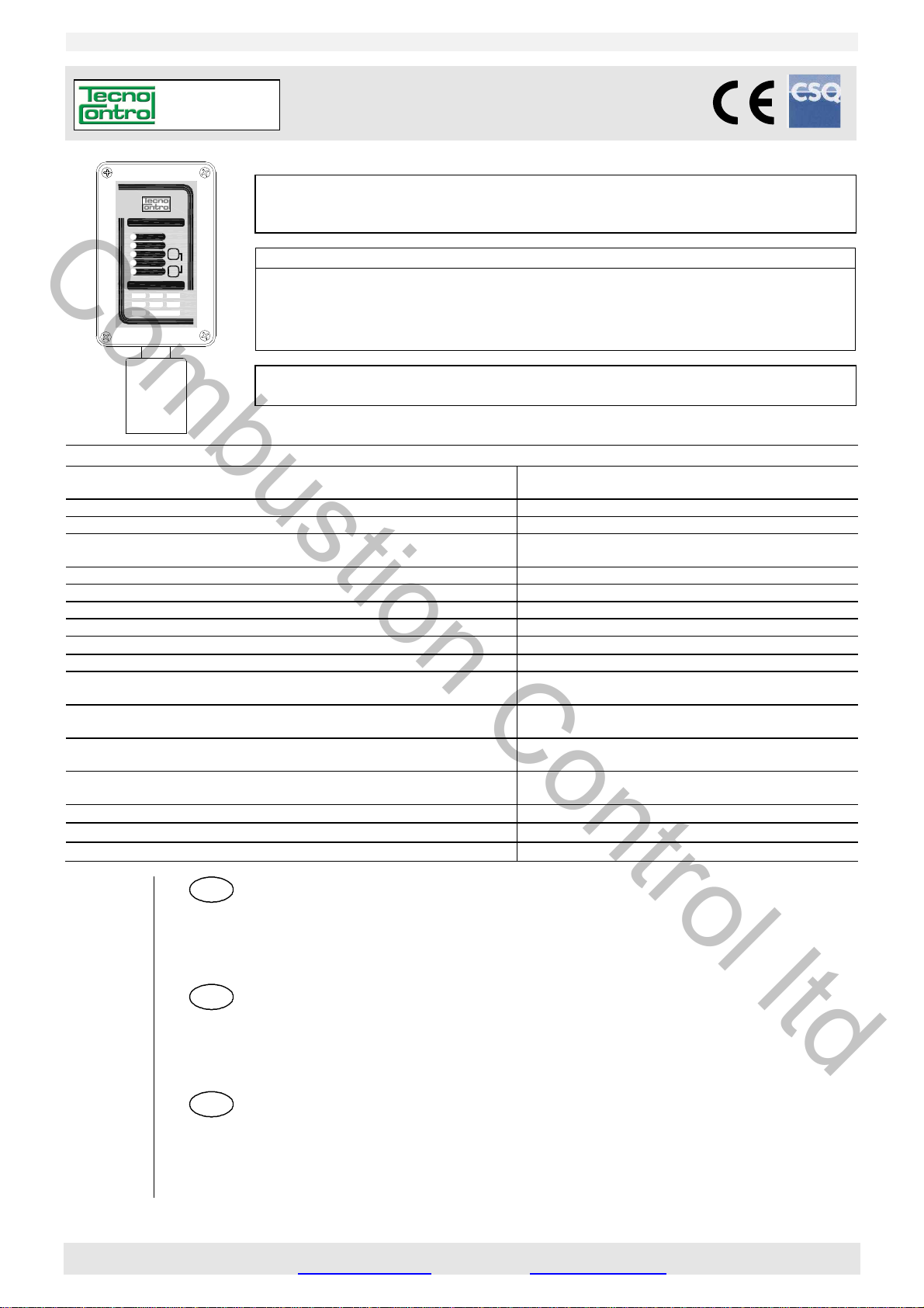
SE137K
SE137
ALARM 3
ALARM 2
F1
A
LARM 1
ON
FAULT
MODEL TYPE
KM KG
PG
PMKXPX
SET
F2
F
2
M
odello / Model / Modele Calibrato per / Calibrated for / Tarée pour Cartuccia/Cartridge/Cartouche
SE137KM Metano
SE137KG G
SE137KI Id
SE137KB B
Inside Replaceable Cartridge Sensor / Avec Cartouche Capteur échangeable
struzione / User’s Manual / Manuel d’utilisation Pag.1/10
Rivelatore di Gas infiammabili con uscita Relé
Flammable Gas Detector with output relay
Détecteur ponctuel de gaz combustibles
L
eggere Attentamente e Conservare quest’Istruzione.
Please read and keep this manual
Lire avec soin et garder la notice d’istruction
/ Methane / Méthane ZSK01 o/or/ou ZSK02
PL / LPG / GPL ZSK01 o/or/ou ZSK02
rogeno / Hydrogen / Hydrogène ZSK01 o/or/ou ZSK02
enzina / Petrol / Essence ZSK04
C
on Cartuccia Sensore Sostituibile
Alimentazione / P
Sensore / Se
Cartuccia Sensore / C
Uscite /
Campo di misura / St
Limite Scala / Limits
Vita media in aria pulita / A
Tempo di risposta T90 / R
Ripetibilità / R
Precisione /
Deriva a lungo termine
L
Temp./umidità di immagazzinamento / St
Température et hygrométrie de stockage
Temp./umidità di funzionamento /
Température et hygrométrie de fonctionnement
Pressione di funzionamento
O
Vibrazioni e Urti /
Dimensioni /
Grado di protezione /
Outputs / Sortie
ong time drift / Dérive à long terme
peration Pressure / Pression de fonctionnement
ower supply / Alimentation
nsor Type / Capteur Catalitico /
artridge Sensor / Cartouche capteur Sostituibile / Replaceable / échangeable
andard Range / Champ de mesure 0 ÷ 20 % LIE /
/ Limite échelle 30 % LIE / LEL
verage Life in fresh air / Vie moyenne en air pur 5 anni / years / ans
esponse Time T
epeatability / Répétitivité
Accuracy / Précision
Vibration and Shocks / Vibrations et chocs
Size / Dimensions du boîtier
IP Code / Indice de protection
DESCRIZIONE ........................................................................................................................... 2
N
OTE SUI VARI MODELLI ..................................................................................................................... 2
FUNZIONAMENTO ................................................................................................................................. 2
INSTALLAZIONE .................................................................................................................................... 3
AVVERTENZE ........................................................................................................................................ 3
VERIFICHE E CALIBRAZIONE .............................................................................................................. 3
DESCRIPTION ........................................................................................................................... 4
N
OTES ON THE AVAILABLE MODELS ................................................................................................ 4
OPERATIONAL DESCRIPTION ............................................................................................................. 4
INSTALLATION ...................................................................................................................................... 5
WARNING ............................................................................................................................................... 5
TEST and CALIBRATION ...................................................................................................................... 6
DESCRIPTION ........................................................................................................................... 6
M
ODÈLES ............................................................................................................................................... 7
FONCTIONNEMENT............................................................................................................................... 7
INSTALLATION ...................................................................................................................................... 8
INSTRUCTIONS ..................................................................................................................................... 8
VÉRIFICATIONS ET ETALONNAGE ..................................................................................................... 8
Temps de réponse T90 <
orage Temp-Humidity
Operation Temp./Humidity
12÷24Vdc(-10/+15%) 3W / 12÷24Vcc(-10/+15%) 3W
non condensata / non condensed / non condensée
non condensata / non condensed / non condensée
Atmospheric±10% / Atmosphérique ±10%
12÷24Vcc (-10/+15%) 3W
Catalytic / Catalytique
relays / relais 2
relè /
4 ÷ 20 mA lineare /
60 secondi / seconds / secondes
5% del segnale /
± 10 %
< ± 4 % LIE anno / LEL year / LIE/an
-20 ÷ + 55°C / 5 ÷ 95 % RH
-10 ÷ + 50 °C / 10÷90 % RH
Atmosferica ±10%
0,35 mm 10-50-10 Hz / ≤ 0,5J
190 x 105 x 83 mm
4V/1A SPST
Linear / linéaire
LEL
signal
IP65
TECNOCONTROL S.r.l. - Via Miglioli, 47 20090 SEGRATE (MI) ITALY Tel. +39 02 26922890 - Fax +39 02 2133734
ww.tecnocontrol.it e-mail: info@tecnocontrol.it
http: w
IST-2137.KM02.01/B Istruzione / User’s Manual / Manuel d’utilisation Pag.4/10
Tel. +39 02 26922890
- Fax +39 02 2133734
EN
Combustion Control ltd
“CALIBRAZIONE”( Codice: F2, F2, F2, F1, F2, F1): questa funzione permette di ritarare il sensore.
Importante: La miscela da utilizzare è Gas Metano al 20%LIE (0,88%v/v) in aria (20,9% Ossigeno circa).
AVVISO: per garantire che non avvengano errori d’elaborazione, esiste la rara possibilità che in Calibrazione, il
Led Giallo si spenga ogni 8 secondi, in questo caso interrompere la procedura, spegnere e riaccendere
l’apparecchio. Ripetere la Calibrazione, se la condizione persiste sarà necessario inviare il rilevatore al fornitore
per la riparazione.
Attenzione: Durante la Calibrazione l’uscita in mA diventerà 0 mA.
La Taratura va eseguita solo in aria pulita (ambiente senza la presenza di gas infiammabili o altri inquinanti). Con i
tasti eseguire il “Codice Calibrazione”. Attendere che i Led Giallo e Verde si accendano fissi e il 1° Led Rosso inizi a
lampeggiare. Infilare il TC011 sul portasensore, regolare l’afflusso del gas, in modo che il flussometro indichi circa
0,3 l/min (vedi Fig.3). Attendere circa 3 minuti, poi, quando il 3° Led Rosso si accende (e mentre è ACCESO), premere il tasto F2 sulla targa dell’apparecchio e tenerlo premuto finché 1° e 3° Led Rosso non rimangano spenti per
almeno 2 secondi (se il 1° Led Rosso continua a lampeggiare, attendere che il 3° Led Rosso si riaccenda e ripetere
l’operazione). Chiudere la bombola e togliere il TC011. A questo punto si possono verificare due casi:
Led Giallo e Verde accesi: la calibrazione è stata eseguita correttamente, dopo 8 secondi l’apparecchio si spegne e si riavvia automaticamente in funzionamento normale (vedi capitolo FUNZIONAMENTO “ Preriscaldo”).
Led Giallo acceso: la calibrazione è fallita. In questo caso, dopo 8 secondi si riavvia automaticamente e dopo il
preriscaldo, ripetere la procedura di “Calibrazione” senza reinserire il “Codice”. Se la condizione persiste anche dopo
la sostituzione della cartuccia sarà necessario inviare il rilevatore al fornitore per la riparazione.
“VERIFICA”( Codice: F2, F1, F2, F1): questa funzione, serve per controllare la corretta risposta del rilevatore al
Gas e può essere effettuata sia dopo la “Calibrazione” sia dopo l’installazione, ma va eseguita soprattutto durante le
manutenzioni periodiche, in quanto è l’unico metodo per controllare l’effettivo funzionamento dell’apparato.
La Verifica va eseguita utilizzando la miscela Gas Metano 20%LIE (0,88%v/v) in aria (20,9% Ossigeno circa).
Con i tasti eseguire il “Codice Verifica”. Infilare il TC011 sul portasensore, regolare il riduttore della Bombola in modo
che il flussometro indichi circa 0,3 l/min (vedi Fig.3). Attendere circa 3 minuti e controllare che il rilevatore vada in
allarme come decritto nel capitolo “Funzionamento”. Se il risultato è diverso, è opportuno effettuare la “Calibrazio-
ne”. Terminata la “Verifica”, chiudere la bombola, togliere il TC011 e premere il tasto F2 sulla targa per ripristina-
re le condizioni di funzionamento normale.
NOTA: In aggiunta a quanto sopra, se si usa anche l’uscita in mA, controllare anche, con i puntali del volmetro sui
Test-Point “TESTmA”, (vedi Fig.2) si raggiunga un valore tra 184 e 216 mV. [ovvero che l’uscita in mA aumenti fino a circa 20
mA (±1,6) e la centrale, cui è collegato il Trasmettitore, indichi circa 20%LIE (± 2)]. Poi l’uscita, tornerà progressivamente a 4 mA.
DESCRIPTION
The SE137K series is a flammable gas detector employing a catalytic sensor and find their best application in centralized alarm systems for car parks, manufacturing industries, etc. The instruments comprise of a thermoplastic
case in which the electronic circuit and the terminals are mounted. The enclosure has downward facing cylindrical
sensor housing with inside a replaceable “Cartridge Sensor” The detector has three alarm levels, with different setup as listed in Table 2. The sealed relays are with tension free single pol
shows the working conditions.
3rd Red LED "ALARM 3": 3rd relay activation
2nd Red LED "ALARM 2": 2nd relay activation
1st Red LED "ALARM 1": 1st relay activation
Green LED "ON": normal working condition
Yellow LED "FAULT": the sensor should be faulty, disconnected, out of scale or expired.
The instrument has a 4÷20mA linear output (S) with 20%LIE F.S. of detected gas. This output is connectable to a
remote Central Unit and/or used for the Test and Calibration routine, protected by a code, with F1 e F2 key.
e contacts (SPST). On the front panel 5 Led
NOTES ON THE AVAILABLE MODELS
SE137KM (Methane CH4) is calibrated to detect Methane, a gas lighter than air. Its density as to air is 0.55 and
its LEL (Lower Explosive Limit) is 4.4%v/v (%volume).
SE137KG (GPL) is calibrated to detect LPG, a gas heavier than air and consists of a mixture of 20÷30% Propane
(C3H8) and 80÷70% Butane (C4H10). Propane density as to air is 1.56 while Butane' is 2.05. The LEL is 1.7%v/v
for Propane and 1.4%v/v for Butane. Standard calibration to LPG is carried out for Butane gas.
SE137KI (Hydrogen H2) is calibrated to detect Hydrogen, is a colourless, odourless, highly flammable gas and is
the lightest gas. Its density as to air is 0.07 and its LEL (Lower Explosive Limit) is 4%v/v (%volume).
SE137KB (Unleaded Gasoline/Petrol) is calibrated to detect Gasoline vapours heavier than air and highly flammable. Its density as to air about 2.8 and its LEL (Lower Explosive Limit) is about 1.2%v/v (%volume).
OPERATIONAL DESCRIPTION
The catalytic sensor is practically insensitive to humidity and temperature variations. The calibration is carried out
for the specific gas to be detected. Anyway, it can contemporaneously detect any other flammable gas that should
be present in the same environment.
Preheating: when powered, the sensor needs a time of preliminary heating of about 60 seconds. During this peri-
od the yellow LED “FAULT” flashes. After this period, the yellow LED light off, the green LED “ON” illuminates to indicate normal functioning. After this period the unit is able to detect gas even if it attains the optimum stability conditions after about 4 hours continual functioning.
TECNOCONTROL S.r.l. Via Miglioli 47 SEGRATE ( MI )
 Loading...