

IST-2137.KM02.01/B I
(
IST-2137.KM02.01
-
B_SE137K (30.04.2014).docx
)
Caratteristiche tecniche /
Technical specifications
/
Caractéristiques techniques
90 /
≤
IT
EN
FR
Combustion Control ltd
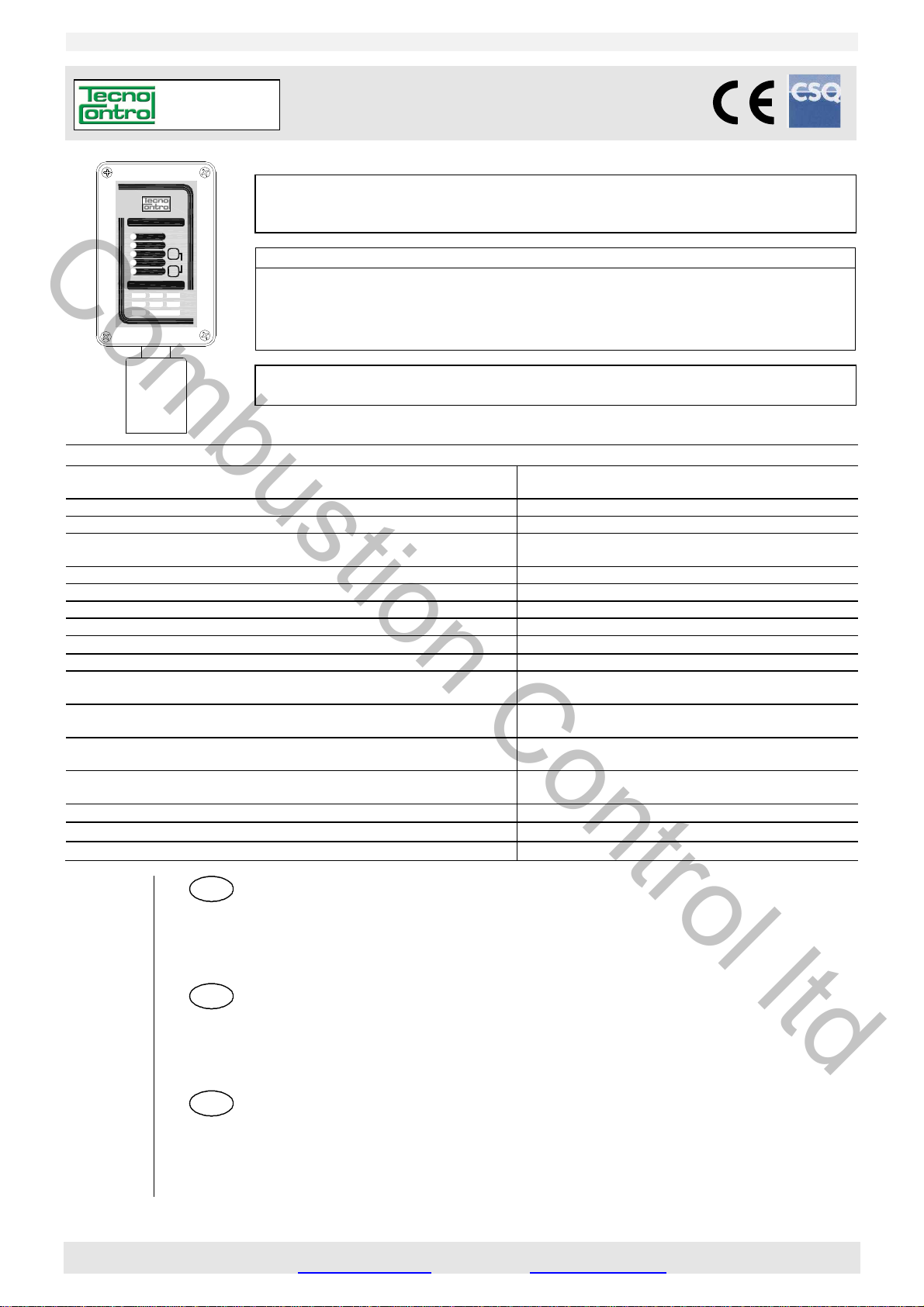
SE137K
SE137
ALARM 3
ALARM 2
F1
A
LARM 1
ON
FAULT
MODEL TYPE
KM KG
PG
PMKXPX
SET
F2
F
2
M
odello / Model / Modele Calibrato per / Calibrated for / Tarée pour Cartuccia/Cartridge/Cartouche
SE137KM Metano
SE137KG G
SE137KI Id
SE137KB B
Inside Replaceable Cartridge Sensor / Avec Cartouche Capteur échangeable
struzione / User’s Manual / Manuel d’utilisation Pag.1/10
Rivelatore di Gas infiammabili con uscita Relé
Flammable Gas Detector with output relay
Détecteur ponctuel de gaz combustibles
L
eggere Attentamente e Conservare quest’Istruzione.
Please read and keep this manual
Lire avec soin et garder la notice d’istruction
/ Methane / Méthane ZSK01 o/or/ou ZSK02
PL / LPG / GPL ZSK01 o/or/ou ZSK02
rogeno / Hydrogen / Hydrogène ZSK01 o/or/ou ZSK02
enzina / Petrol / Essence ZSK04
C
on Cartuccia Sensore Sostituibile
Alimentazione / P
Sensore / Se
Cartuccia Sensore / C
Uscite /
Campo di misura / St
Limite Scala / Limits
Vita media in aria pulita / A
Tempo di risposta T90 / R
Ripetibilità / R
Precisione /
Deriva a lungo termine
L
Temp./umidità di immagazzinamento / St
Température et hygrométrie de stockage
Temp./umidità di funzionamento /
Température et hygrométrie de fonctionnement
Pressione di funzionamento
O
Vibrazioni e Urti /
Dimensioni /
Grado di protezione /
Outputs / Sortie
ong time drift / Dérive à long terme
peration Pressure / Pression de fonctionnement
ower supply / Alimentation
nsor Type / Capteur Catalitico /
artridge Sensor / Cartouche capteur Sostituibile / Replaceable / échangeable
andard Range / Champ de mesure 0 ÷ 20 % LIE /
/ Limite échelle 30 % LIE / LEL
verage Life in fresh air / Vie moyenne en air pur 5 anni / years / ans
esponse Time T
epeatability / Répétitivité
Accuracy / Précision
Vibration and Shocks / Vibrations et chocs
Size / Dimensions du boîtier
IP Code / Indice de protection
DESCRIZIONE ........................................................................................................................... 2
N
OTE SUI VARI MODELLI ..................................................................................................................... 2
FUNZIONAMENTO ................................................................................................................................. 2
INSTALLAZIONE .................................................................................................................................... 3
AVVERTENZE ........................................................................................................................................ 3
VERIFICHE E CALIBRAZIONE .............................................................................................................. 3
DESCRIPTION ........................................................................................................................... 4
N
OTES ON THE AVAILABLE MODELS ................................................................................................ 4
OPERATIONAL DESCRIPTION ............................................................................................................. 4
INSTALLATION ...................................................................................................................................... 5
WARNING ............................................................................................................................................... 5
TEST and CALIBRATION ...................................................................................................................... 6
DESCRIPTION ........................................................................................................................... 6
M
ODÈLES ............................................................................................................................................... 7
FONCTIONNEMENT............................................................................................................................... 7
INSTALLATION ...................................................................................................................................... 8
INSTRUCTIONS ..................................................................................................................................... 8
VÉRIFICATIONS ET ETALONNAGE ..................................................................................................... 8
Temps de réponse T90 <
orage Temp-Humidity
Operation Temp./Humidity
12÷24Vdc(-10/+15%) 3W / 12÷24Vcc(-10/+15%) 3W
non condensata / non condensed / non condensée
non condensata / non condensed / non condensée
Atmospheric±10% / Atmosphérique ±10%
12÷24Vcc (-10/+15%) 3W
Catalytic / Catalytique
relays / relais 2
relè /
4 ÷ 20 mA lineare /
60 secondi / seconds / secondes
5% del segnale /
± 10 %
< ± 4 % LIE anno / LEL year / LIE/an
-20 ÷ + 55°C / 5 ÷ 95 % RH
-10 ÷ + 50 °C / 10÷90 % RH
Atmosferica ±10%
0,35 mm 10-50-10 Hz / ≤ 0,5J
190 x 105 x 83 mm
4V/1A SPST
Linear / linéaire
LEL
signal
IP65
TECNOCONTROL S.r.l. - Via Miglioli, 47 20090 SEGRATE (MI) ITALY Tel. +39 02 26922890 - Fax +39 02 2133734
ww.tecnocontrol.it e-mail: info@tecnocontrol.it
http: w
IST-2137.KM02.01/B Istruzione / User’s Manual / Manuel d’utilisation Pag.4/10
Tel. +39 02 26922890
- Fax +39 02 2133734
EN
Combustion Control ltd
“CALIBRAZIONE”( Codice: F2, F2, F2, F1, F2, F1): questa funzione permette di ritarare il sensore.
Importante: La miscela da utilizzare è Gas Metano al 20%LIE (0,88%v/v) in aria (20,9% Ossigeno circa).
AVVISO: per garantire che non avvengano errori d’elaborazione, esiste la rara possibilità che in Calibrazione, il
Led Giallo si spenga ogni 8 secondi, in questo caso interrompere la procedura, spegnere e riaccendere
l’apparecchio. Ripetere la Calibrazione, se la condizione persiste sarà necessario inviare il rilevatore al fornitore
per la riparazione.
Attenzione: Durante la Calibrazione l’uscita in mA diventerà 0 mA.
La Taratura va eseguita solo in aria pulita (ambiente senza la presenza di gas infiammabili o altri inquinanti). Con i
tasti eseguire il “Codice Calibrazione”. Attendere che i Led Giallo e Verde si accendano fissi e il 1° Led Rosso inizi a
lampeggiare. Infilare il TC011 sul portasensore, regolare l’afflusso del gas, in modo che il flussometro indichi circa
0,3 l/min (vedi Fig.3). Attendere circa 3 minuti, poi, quando il 3° Led Rosso si accende (e mentre è ACCESO), premere il tasto F2 sulla targa dell’apparecchio e tenerlo premuto finché 1° e 3° Led Rosso non rimangano spenti per
almeno 2 secondi (se il 1° Led Rosso continua a lampeggiare, attendere che il 3° Led Rosso si riaccenda e ripetere
l’operazione). Chiudere la bombola e togliere il TC011. A questo punto si possono verificare due casi:
Led Giallo e Verde accesi: la calibrazione è stata eseguita correttamente, dopo 8 secondi l’apparecchio si spegne e si riavvia automaticamente in funzionamento normale (vedi capitolo FUNZIONAMENTO “ Preriscaldo”).
Led Giallo acceso: la calibrazione è fallita. In questo caso, dopo 8 secondi si riavvia automaticamente e dopo il
preriscaldo, ripetere la procedura di “Calibrazione” senza reinserire il “Codice”. Se la condizione persiste anche dopo
la sostituzione della cartuccia sarà necessario inviare il rilevatore al fornitore per la riparazione.
“VERIFICA”( Codice: F2, F1, F2, F1): questa funzione, serve per controllare la corretta risposta del rilevatore al
Gas e può essere effettuata sia dopo la “Calibrazione” sia dopo l’installazione, ma va eseguita soprattutto durante le
manutenzioni periodiche, in quanto è l’unico metodo per controllare l’effettivo funzionamento dell’apparato.
La Verifica va eseguita utilizzando la miscela Gas Metano 20%LIE (0,88%v/v) in aria (20,9% Ossigeno circa).
Con i tasti eseguire il “Codice Verifica”. Infilare il TC011 sul portasensore, regolare il riduttore della Bombola in modo
che il flussometro indichi circa 0,3 l/min (vedi Fig.3). Attendere circa 3 minuti e controllare che il rilevatore vada in
allarme come decritto nel capitolo “Funzionamento”. Se il risultato è diverso, è opportuno effettuare la “Calibrazio-
ne”. Terminata la “Verifica”, chiudere la bombola, togliere il TC011 e premere il tasto F2 sulla targa per ripristina-
re le condizioni di funzionamento normale.
NOTA: In aggiunta a quanto sopra, se si usa anche l’uscita in mA, controllare anche, con i puntali del volmetro sui
Test-Point “TESTmA”, (vedi Fig.2) si raggiunga un valore tra 184 e 216 mV. [ovvero che l’uscita in mA aumenti fino a circa 20
mA (±1,6) e la centrale, cui è collegato il Trasmettitore, indichi circa 20%LIE (± 2)]. Poi l’uscita, tornerà progressivamente a 4 mA.
DESCRIPTION
The SE137K series is a flammable gas detector employing a catalytic sensor and find their best application in centralized alarm systems for car parks, manufacturing industries, etc. The instruments comprise of a thermoplastic
case in which the electronic circuit and the terminals are mounted. The enclosure has downward facing cylindrical
sensor housing with inside a replaceable “Cartridge Sensor” The detector has three alarm levels, with different setup as listed in Table 2. The sealed relays are with tension free single pol
shows the working conditions.
3rd Red LED "ALARM 3": 3rd relay activation
2nd Red LED "ALARM 2": 2nd relay activation
1st Red LED "ALARM 1": 1st relay activation
Green LED "ON": normal working condition
Yellow LED "FAULT": the sensor should be faulty, disconnected, out of scale or expired.
The instrument has a 4÷20mA linear output (S) with 20%LIE F.S. of detected gas. This output is connectable to a
remote Central Unit and/or used for the Test and Calibration routine, protected by a code, with F1 e F2 key.
e contacts (SPST). On the front panel 5 Led
NOTES ON THE AVAILABLE MODELS
SE137KM (Methane CH4) is calibrated to detect Methane, a gas lighter than air. Its density as to air is 0.55 and
its LEL (Lower Explosive Limit) is 4.4%v/v (%volume).
SE137KG (GPL) is calibrated to detect LPG, a gas heavier than air and consists of a mixture of 20÷30% Propane
(C3H8) and 80÷70% Butane (C4H10). Propane density as to air is 1.56 while Butane' is 2.05. The LEL is 1.7%v/v
for Propane and 1.4%v/v for Butane. Standard calibration to LPG is carried out for Butane gas.
SE137KI (Hydrogen H2) is calibrated to detect Hydrogen, is a colourless, odourless, highly flammable gas and is
the lightest gas. Its density as to air is 0.07 and its LEL (Lower Explosive Limit) is 4%v/v (%volume).
SE137KB (Unleaded Gasoline/Petrol) is calibrated to detect Gasoline vapours heavier than air and highly flammable. Its density as to air about 2.8 and its LEL (Lower Explosive Limit) is about 1.2%v/v (%volume).
OPERATIONAL DESCRIPTION
The catalytic sensor is practically insensitive to humidity and temperature variations. The calibration is carried out
for the specific gas to be detected. Anyway, it can contemporaneously detect any other flammable gas that should
be present in the same environment.
Preheating: when powered, the sensor needs a time of preliminary heating of about 60 seconds. During this peri-
od the yellow LED “FAULT” flashes. After this period, the yellow LED light off, the green LED “ON” illuminates to indicate normal functioning. After this period the unit is able to detect gas even if it attains the optimum stability conditions after about 4 hours continual functioning.
TECNOCONTROL S.r.l. Via Miglioli 47 SEGRATE ( MI )

IST-2137.KM02.01/B Istruzione / User’s Manual / Manuel d’utilisation Pag.5/10
Tel. +39 02 26922890
- Fax +39 02 2133734
Combustion Control ltd
Normal operation: the green LED “ON” should be light on.
The 1st° Red LED (ALARM 1) illuminates when the Gas concentration attains 1st alarm level and after about 12
seconds , the “ALARM 1" relay will activate.
The 2nd Red LED (ALARM 2) illuminates when the Gas concentration attains 2nd alarm level and after about 30
seconds, the “ALARM 2" relay will activate.
The 3rd Red LED (ALARM 3) illuminates when the Gas concentration attains 3rd alarm level and after about 60
seconds, the “ALARM 3" relay will activate.
Faults: the instrument signal different kind of failures, as listed below. The Yellow LED illuminates, the "S" output
falls down to 0mA and the “FAULT” normally activated relay deactivate. The "FAULT" relay, if necessary, can be used
both to signal remotely an occurred damage and to signal the absence of power to the instrument.
Yellow LED illuminates each 4 seconds (with Green LED activate): this happens when the “Cartridge Sensor” has
overcome its period of life (about 5 years) and its correct operation is not longer guaranteed. The detector keeps on
operating normally but it is necessary to replace, as soon as possible, the “Cartridge Sensor” with a new one. The
type to be required is listed in 2nd column Table 4. The replacement procedure is described in the attached manual.
Yellow LED activate, Green LED off (FAULT relays activate and 0mA output signal): this signal different kind of
faults. 1) The Dip Switch set up is wrong, please verify (see Table 2-3). 2
please replace with new one. 3) If a new “Cartridge Sensor” is installed or it is not correctly connected or a not
compatible one is mounted. Please check the cartridge connections and compatibility (see Table 4) these checks are
made connecting and disconnecting the device. If the condition does not change, it will be necessary to replace the
unit and/or send it back to the supplier to repair.
Yellow and Green LED activates (FAULT relays activate and 0mA output signal): this happens when the “Cartridge
Sensor” is not working. First try to perform the procedure of “ZERO” as described in the section “Test and Calibra-
tion > Zero adjust” then disconnect and connect the unit, finally try to replace a new “Cartridge Sensor”. If the
condition is not change, it will be necessary to replace the unit and/or send it back to the supplier to repair.
All LED activate (FAULT relays activate and >24mA output signal): this happens when the “Cartridge Sensor” is not
working or gas concentration is out of scale (higher than 25% LIE) If there are not any gas leaks and the condition
is not change, it will be necessary to replace the unit and/or send it back to the supplier to repair.
) The “Cartridge Sensor” is not working,
INSTALLATION
The detector must be accurately installed according to the national dispositions in force on the safety of the plants
and installation of electric devices in areas with danger of explosion.
Mounting: The Fig. 2 shows the instrument size. The unit must be positioned vertically with the sensor downwards.
Models SE137KG and SE137KB should be fixed at 20-30 cm from the floor (LPG and Petrol vapours are heavier than air).
Models SE137KM and SE137KI should be fixed at 20-30 cm from the ceiling (Methane and Hydrogen are lighter than air).
Electrical Connection (see Fig.2): the maximum distance to install each detector from the power supply show in the
Table 1. If more than one detector is to be powered in parallel, it is necessary to consider the voltage drop across
the supply cable. Normally use a two wire cable (not shielded) for power supply + the conductors for output relay. If
the output signal is used in mA, please use 3 conductors screened cables + conductors for relay output. The max load
resistor is 50 ohm with 12Vdc (-10%) power supply, while is 500 ohm with 24Vdc (-10%) power supply (see fig.4).
ower Supply terminals, on the main board, are plug-in type, it is necessary to extract them to make the connection.
P
Pay attention when you insert them again, being polarized. The relays terminals, on outputs board, are fixed. The
sealed relays are tension free SPST (Single Pole Single Throw) contacts and should be set NO (Normally Open) or NC
(Normally Closed) by positioning the 4th Dip-Switch (see Table 3). With the Dip-Switches from 1 to 3 the concentration for alarm activations is determined.
Note: Dip-Switch should be set with instrument powered off. Dip-Switch settled in reserved position activate Fault
indications (see “Operational Description > Faults”).
Important: Once installation is completed, it is necessary to adjust the sensor to the environment conditions, con-
nect the unit, wait about 20÷30 minutes and the carry out the ”Zero Ad just” (see ‘Test and Calibration >).
WARNING
Average life: The sensitive element used in this detector has an excellent stability in time. In fresh air and in normal working condition the sensor's life is about 5 years from the date of installation. After this period the yellow LED
“FAULT” flashes every 4 seconds, is necessary replacing the “Cartridge Sensor”.
Periodical testing: we advise to carry out working tests every 12 months. Tests, Zero Adjust and Calibration with
Gas/Air mixture as explained on page 4 chapter “Tests and Calibration”.
Note: the detector is not able to detect gas leaks occurring outside the room where it is installed, neither inside
walls nor under the floor.
Important: The catalytic sensor operates only in presence of Oxygen. Do not use pure gases or a lighter directly
on the sensor since they could damage it irremediably.
Warning: some substances cause a permanent reduction in sensitivity. Avoid contacts of the sensor with vapours
of Silicone compounds, Tetra-ethyl Lead (petrol antiknock additive) and Phosphate esters, since they can reduce
irremediably its sensitivity. Some substances produce a temporary loss of sensitivity. This “inhibitors” include Hydrogen sulphides, Chlorine, Chlorinated hydrocarbons and halogenated compounds. The sensitivity is recovered
after a short period of running in clear air.
TECNOCONTROL S.r.l. Via Miglioli 47 SEGRATE ( MI )

IST-2137.KM02.01/B Istruzione / User’s Manual / Manuel d’utilisation Pag.6/10
Tel. +39 02 26922890
- Fax +39 02 2133734
FR
Combustion Control ltd
TEST and CALIBRATION
PAY ATTENTION: This procedure has to be made with extreme attention and by authorized and trained people;
because starting this procedure it will start both Outputs (relays) causing the activation of connected alarm devices.
The instrument has three different code protected functions: Operation Check, Zero Adjust and Calibration.
Operation Check, Zero Adjust, Calibration Check and Calibration: are different code protected functions. To ac-
cess these functions is necessary to insert the relevant “Code" through the keys F1s and F2. To have the key pressure recognized, hold pressing it for around a second (until the Green Led doesn't switch off for a moment). Then the next key
can be pressed. In case of error all it takes is waiting around 10 seconds and the sequence is automatically erased.
Calibration Kit, Sample Gas Bottles (for Calibration Check and Calibration) please, only using a mixture 20%LEL
(0.88%v/v) Methane in Air (20.9% Oxygen). Catalytic sensors cannot work without Oxygen. It is possible to use
either the disposable one litre cylinders with adjust valve or the high pressure ones with reduction gear. Is also
necessary the Tecnocontrol Calibration Kit model TC011.
“INSTRUMENT OPERATION CHECK” (Check Code: F2, F2, F1, F1): this function allows to effect a functional test
of the equipment. After having put the system in safety and inserted the "Code Test", all Led are switched off and all
the relays are disarmed. Then they will switch on in sequence, the Led, from the yellow up to the 3° red. To the
lighting of the various Led it corresponds the activation of the relevant relays (relay "FAULT" with the yellow Led, relay
"ALARM1" with the 1° red Led, relay "ALARM2" with the 2° red Led, relay "ALARM3" with the 3° red Led). At the end all the Led will
remain lighted for around 5 seconds, then the central returns at the conditions of normal operation. It is advisable to
perform this operation every 6-12 months according to the use.
Note: this function is not working if the 1° and/or the 2° and/or the 3° red Led have already turned on
“ZERO ADJUST” (Zero Code: F2, F1, F1, F2): this function is to adjust the Zero sensor and can be done in clean
air only (environment without the presence of gas or other pollutants). Immediately after having inserted the "Zero
Code", as a confirmation of the operation carried out there will be 1 I flash of the 1° red Led and the output will be-
come 4,0 mA. We suggest performing this operation after the installation or after the change of the cartridge and
every 6-12 months based on the environmental conditions.
Note: This function is not working if the 2° e/o the 3° red Led have already been switched on .In case the 1°
red Led is already switched on only instead of flashing it will switch off for confirmation.
“CALIBRATION” (Calibration Code: F2, F2, F2, F1, F2, F2): this function allows completely recalibrate the sensor.
Warning: to guarantee that no errors of elaboration happen, the rare possibility exists that during the Calibration
the yellow LED switch off every 8 seconds, in this case interrupt the procedure, switch off and witch on the instrument and repeat the Calibration. If condition persists it will be necessary to send the detector to the supplier for the
reparation. Important note: During Calibration routine the mA output indicates 0mA.
The Calibration can be done in clean air only (environment without the presence of flammable or other polluting gas). With the
keys perform the “Calibration Code ". Wait until the Yellow and Green Led switch on fix and the 1° red Led starts to
flash. Insert the TC011 into the sensor holder to regulate the influx of the gas the way that the flow meter indicates
around 0.3 l/mins (see Fig.3). Wait around 3 minutes, then when the 3° red Led switch on (and while it's SWITCHED ON),
press the key F2 on the instrument and hold it pressed until 1° and 3° Red Led are switched off for at least 2 seconds (if the 1° Red Led continue to flash, wait that the 3° Red Led switch on again and repeat the operation). Then, close the gas cyl-
inder and remove TC011. At this point we can have two possibilities:
Yellow and Green Led illuminates: the calibration routine has correctly been performed. Wait 8 seconds, until
the instrument automatically restores the normal working conditions. (see “Operational Description > Preheating”)
Yellow LED illuminates: the routine has failed. In this case, wait 8 seconds, until the instrument automatically re-
peat Preheating, then repeat the “Calibration” routine without inserting again the code. If condition still persists after the
replacement of the cartridge, it will be necessary to send the detector back to the manufacturer for reparation.
“CALIBRATION CHECK” (Cal Check Code: F2, F1, F2, F1): this operation allow to effect a real functional test of
the equipment with gas after the "Calibration" routine, or after the installation. The “Calibration Check” routine should
be done during the periodic maintenances because this is the only method to verify the instrument real functioning.
With the keys perform the " Cal Check Code ". Wait until the Yellow Led starts to flash (the green one remain fix) Insert the TC011 over the sensor holder, adjust the sample gas bottle valve as the flow meter indicates around 0.3
l/mins (see Fig.3), wait for 3 minutes and check that the instrument activates Alarms as shown in chapter “Operational
Description”. If the result is different, is necessary to recalibrate the sensor (see “Calibration”). Then, close the gas bot-
tle, remove TC011, press the key F2 on the instrument to restore the normal working conditions.
NOTE: further to the above, If the mA output is also used, verify with a voltmeter connected to the Test-Point
“TESTmA”, the value reach a value between 184 and 216mV, [corresponding to 20mA (±1.6) output and the central
unit should be display about 20% LEL (±2)]. Then, the mA output will slowly decrease up to 4mA.
DESCRIPTION
Le SE137K est un détecteur ponctuel pour gaz et vapeurs combustibles avec capteur catalytique pouvant également être utilisé en systèmes centralisés d'alarme pour l’industrie et le tertiaire. Le détecteur est constitué par une
boîtier contenant le circuit électronique et les borniers de raccordement; dans le porte capteur, placé dans la partie
inférieure du boîtier, est logée une "cartouche capteur échangeable" contenant l'élément sensible et les données
identificatrices et de réglage. Le SE137K possède 3 relais d'alarmes réglables en % de la LIE (Limite Inférieur d'explo-
sivité), intervenant comme indiqués au Tableau 2 et 1 relais de dérangement.
TECNOCONTROL S.r.l. Via Miglioli 47 SEGRATE ( MI )
 Loading...