

Tecnocontrol Easy 503, 3.300.1766-CR220, 3.301.1767-CR221 Programming Instructions And Installation Manual
Art.
3.300.1766 - CR220
3.301.1767 - CR221
Il Cronotermostato
The Chronothermostat
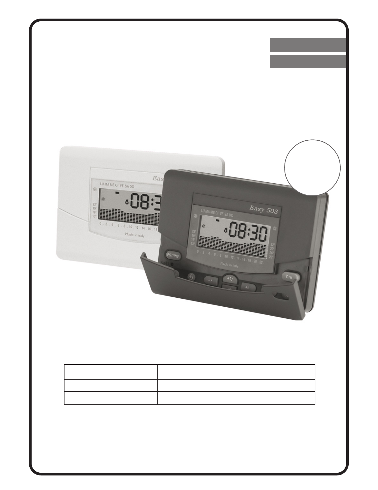
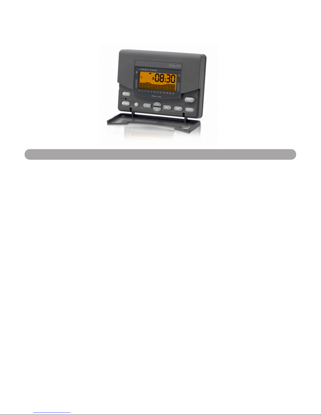
Easy 503
ISTRUZIONI PER L’USO E L’INSTALLAZIONE
PROGRAMMING INSTRUCTIONS AND INSTALLATION GUIDE
MadeMade
MadeMade
Made
inin
inin
in
ItalyItaly
ItalyItaly
Italy
Easy 503
Easy 503
Bianco/
White
Easy 503
Antracite/
Anthracite
Italiano
English
DESCRIZIONE GENERALEDESCRIZIONE GENERALE
DESCRIZIONE GENERALEDESCRIZIONE GENERALE
DESCRIZIONE GENERALE
Easy 503
è un cronotermostato elettronico giornaliero e settimanale che permette di programmare la temperatura della vostra casa ogni ora del giorno per tutti i giorni della settimana.
Easy 503
è dotato di un display retroilluminato con
visualizzazione grafica delle temperature programmate,
modificabili mediante comandi semplici e funzionali che ne facilitano la programmazione.
Easy 503
evita gli sprechi di energia azionando l’impianto di ri-
scaldamento o condizionamento solo quando serve.
GENERAL DESCRIPTIONGENERAL DESCRIPTION
GENERAL DESCRIPTIONGENERAL DESCRIPTION
GENERAL DESCRIPTION
The Easy 503 chronothermostat is a daily and weekly electronic
chronothermostat that permits the programming of the temperature of your home every hour of the day, every day of the
week.
The Easy 503 chronothermostat is equipped with a backlight
display and a graphic visualisation of the programmed temperature that can be
modified by simple and functional commands that facilitate the
programming. The Easy 503 chronothermostat avoids wasting
energy by activating the heating or air-conditioning system only
when needed.
Easy 503
2
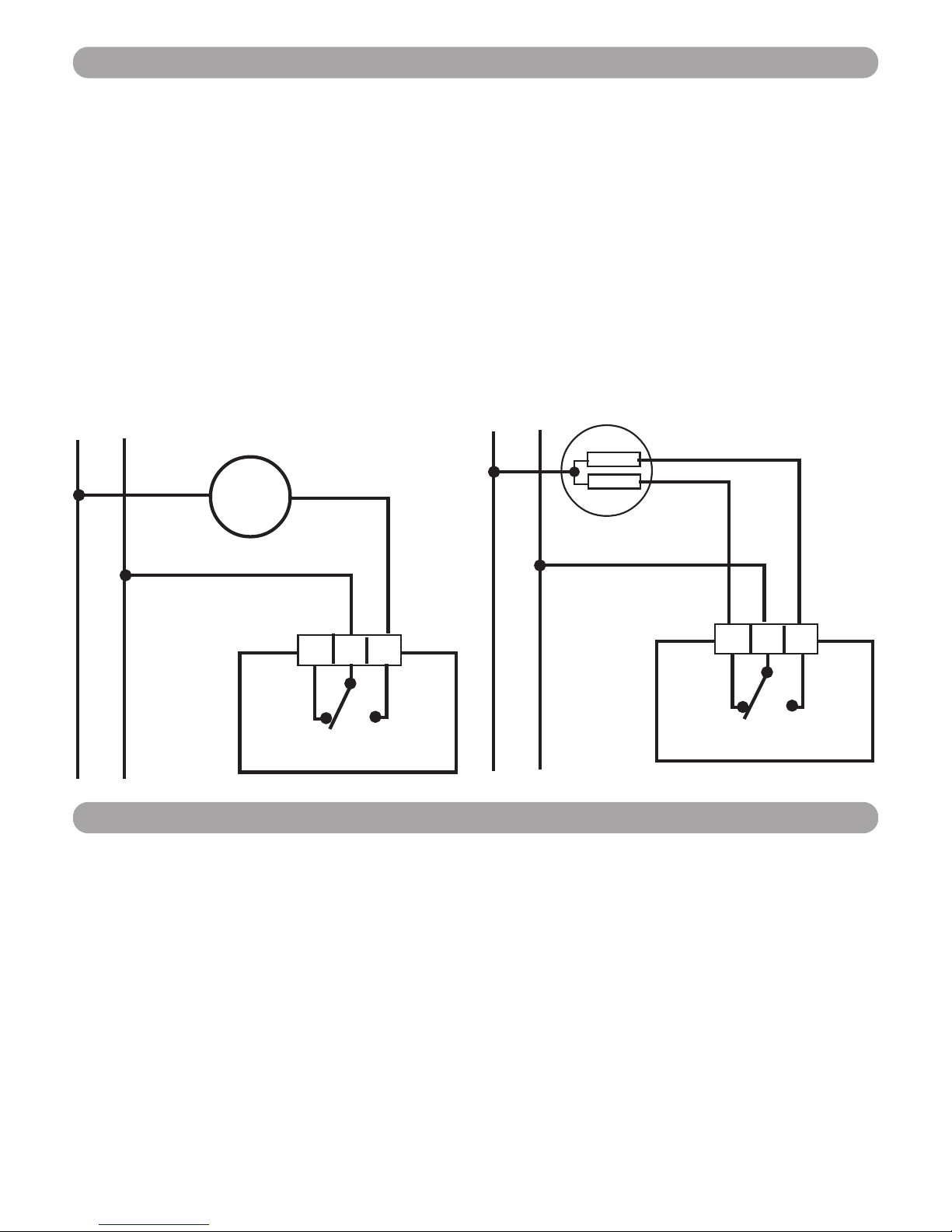
Collegamento con bruciatore, caldaia murale, impianto di
condizionamento, valvola di zona con ritorno a molla (Fig.1A).
Collegamento con valvola di zona (Fig.1B):
COLLEGAMENTO ELETTRICOCOLLEGAMENTO ELETTRICO
COLLEGAMENTO ELETTRICOCOLLEGAMENTO ELETTRICO
COLLEGAMENTO ELETTRICO
POWER CONNECTIONPOWER CONNECTION
POWER CONNECTIONPOWER CONNECTION
POWER CONNECTION
Connection to burner, wall-mounted boiler, air conditioning
system, spring-return zone valve
(Fig.1A)
.
Connection to zone valve (Fig.1B).
3
INSTALLATIONINSTALLATION
INSTALLATIONINSTALLATION
INSTALLATION
Easy 503 can be directly installed on a 3 module recess box or
on the wall. In either cases, it is advisable to position it at a
height of 1,5 meters from the wall, in a dry place, away from
draughts and heat sources.
INSTALLAZIONEINSTALLAZIONE
INSTALLAZIONEINSTALLAZIONE
INSTALLAZIONE
Easy 503
può essere installato direttamente su scatola da incasso 3 moduli oppure su parete.
In entrambi i casi l’altezza consigliata è di 1,5m dal pavimento,
in luogo asciutto, esente da correnti d’aria e lontano da fonti
di calore.
NC C
NA
NO
NC
Apre
Open
Chiude
Close
Easy 503
1 2 3
C
NA
NO
Fig.1B
Easy 503
1 2 3
U
Fig.1A
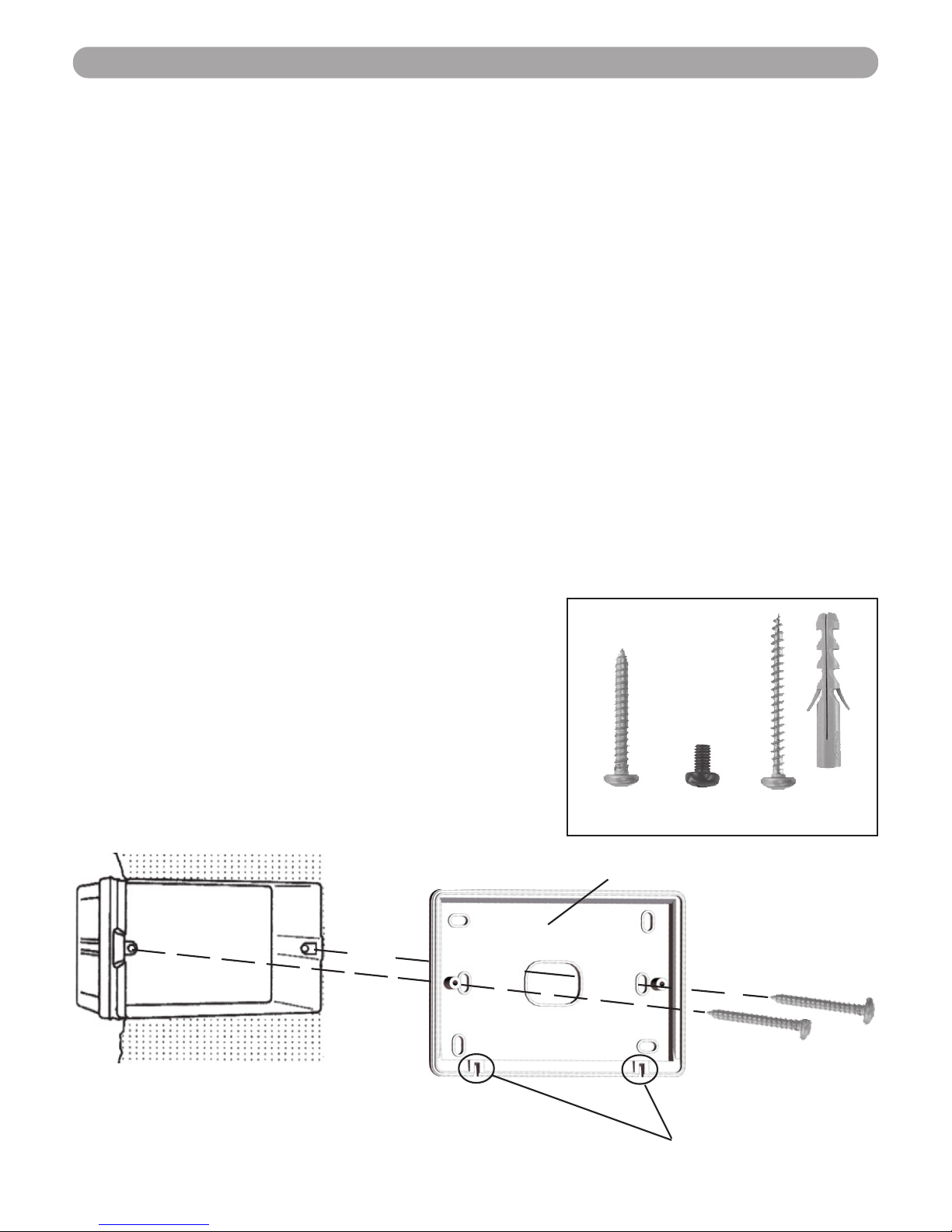
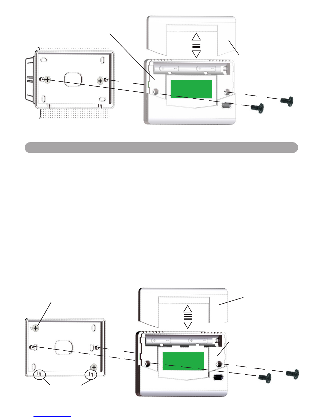
Dopo aver effettuato il collegamento elettrico fissare la BASE
(con le Fessure dell’ANTINA verso il basso) direttamente sulla
scatola da incasso 3 moduli, utilizzando le viti tipo “A” in
dotazione (Fig.2 ).
Alzare il COPRIBATTERIE e fissare il FRONTALE sulla BASE utilizzando le viti tipo “B”. (Fig.3).
Completare l’installazione abbassando il COPRIBATTERIE.
INSTALLAZIONE SU SCATOLA 503INSTALLAZIONE SU SCATOLA 503
INSTALLAZIONE SU SCATOLA 503INSTALLAZIONE SU SCATOLA 503
INSTALLAZIONE SU SCATOLA 503
INSTALLATION ONTO PATTRESS BOX 503INSTALLATION ONTO PATTRESS BOX 503
INSTALLATION ONTO PATTRESS BOX 503INSTALLATION ONTO PATTRESS BOX 503
INSTALLATION ONTO PATTRESS BOX 503
After connecting the wiring, fix the BASE PLATE (with the slots
of the FLAP at the bottom) directly onto the three-gang pattress
box utilizing the type “A” screws supplied (Fig. 2). Lift the
BATTERY COVER and fix the CHRONOTHERMOSTAT UNIT to the
BASE PLATE utilizing the type “B” screws (Fig. 3).
Complete the installation by lowering the BATTERY COVER.
Viti e tasselli in dotazione
Screw and plugs supplied
Scatola incasso
Pattress box
Fig.2
Base
Fessure Antina
Flap Slots
Viti “A”
Screws “A”
4
A B C
INSTALLAZIONE A PARETEINSTALLAZIONE A PARETE
INSTALLAZIONE A PARETEINSTALLAZIONE A PARETE
INSTALLAZIONE A PARETE
Dopo aver fissato la base (con le Fessure dell’ANTINA verso il
basso) alla parete mediante tasselli e viti (tipo “C”) in dotazione, collegare elettricamente il cronotermostato e fissarlo alla
base con le viti tipo “B”. Completare l’installazione abbassando il Copribatterie.
WALL INSTALLATIONWALL INSTALLATION
WALL INSTALLATIONWALL INSTALLATION
WALL INSTALLATION
After fixing the BASE PLATE (with the slots of the FLAP at the
bottom) to the wall using the wall plugs and supplied type “C”
screws, electrically connect the chronothermostat and fix it to
the BASE PLATE using the type “B” screws. Complete the
installation by lowering the BATTERY COVER.
Copribatterie
Battery Cover
Frontale
Chronothermostat unit
Base
Viti “B”
Screws “B”
Fig.3
Fessure Antina
Flap Slots
Viti “C”
Screws “C”
Base
Copribatterie
Battery Cover
Frontale
Chronothermostat
unit
Viti “B”
Screws “B”
5
ALIMENTAZIONEALIMENTAZIONE
ALIMENTAZIONEALIMENTAZIONE
ALIMENTAZIONE
Easy 503
va alimentato con due comuni batterie AA (stilo) Alcaline
da1,5V che ne garantiscono il funzionamento per almeno 2 anni.
Per l’inserimento delle batterie sfilare il COPRIBATTERIE e posizionare le batterie facendo attenzione alla polarità indicata all’interno del vano. (Fig. 4)
Easy 503
è dotato di due soglie di scarica delle batterie.
Superata la prima soglia compare il simbolo BAT ( ) mentre
l’apparecchio continua a funzionare regolarmente.
Al raggiungimento della seconda,
Easy 503
blocca completamente
le sue funzioni di termoregolazione mentre il display presenta
solo l’ora, il giorno ed il simbolo di batteria scarica ( )
lampeggianti.
Durante la sostituzione delle batterie i dati rimangono memorizzati per 30 secondi in assenza di alimentazione.
POWER SUPPLYPOWER SUPPLY
POWER SUPPLYPOWER SUPPLY
POWER SUPPLY
The Easy 503 chronothermostat is powered by two AA 1.5V
alkaline batteries that ensure the chronothermostat operates
for at least two years.
To insert the batteries, slide out the BATTERY COVER and position
the batteries in the correct polarity direction as indicated inside
the compartment (Fig. 4).
The Easy 503 chronothermostat is equipped with two battery
warning discharge levels. When the first level is superseded the
symbol
BAT BAT
BAT BAT
BAT appears ( ) whilst the chronothermostat
continues to function correctly.
On reaching the second level, the chronothermostat completely
blocks its functions of thermoregulation whilst the display shows
the hour, day and the flashing symbol of the discharged battery
( ).
Whilst substituting the batteries, the data remains memorized
for 30 seconds in the absence of power.
6

Fig.4
INIZIALIZZAZIONEINIZIALIZZAZIONE
INIZIALIZZAZIONEINIZIALIZZAZIONE
INIZIALIZZAZIONE
Appena alimentato
Easy 503
effettua un ciclo di controllo accendendo tutti i segmenti del display e attivando il carico per
pochi secondi.
Nel caso l’inizializzazione possa pregiudicare il corretto funzionamento del carico alimentare il cronotermostato prima di
effettuare i collegamenti elettrici.
INITIALISATIONINITIALISATION
INITIALISATIONINITIALISATION
INITIALISATION
As soon as Easy 503 chronothermostat is fed power it carries out
a control cycle switching on all segments of the display and
activating the charge for a few seconds. If the initialization might
prejudice the correct functioning of the charge, power up the
chronothermostat before carrying out the electrical connections.
7

FUNZIONAMENTO E PROGRAMMAZIONEFUNZIONAMENTO E PROGRAMMAZIONE
FUNZIONAMENTO E PROGRAMMAZIONEFUNZIONAMENTO E PROGRAMMAZIONE
FUNZIONAMENTO E PROGRAMMAZIONE
Particolare fondamentale del cronotermostato è il display grafico retroilluminato che presenta un diagramma composto da
24 colonne rappresentanti le ore della giornata; l’altezza di ogni
colonna indica la temperatura programmata per quell’ora. Il segmento in alto a sinistra (A in Fig.5), in corrispondenza delle
scritte sovrastampate, indica il giorno al quale si riferisce il
programma.La temperatura programmata (B in Fig.5) viene
visualizzata in alto a destra durante la programmazione ed è
identificata dal lampeggio del giorno e del simbolo “
CC
CC
C” indican-
te i
°C°C
°C°C
°C.
Durante il funzionamento normale vengono visualizzati alternativamente, premendo il tasto
°C/h°C/h
°C/h°C/h
°C/h (Fig.5), l’orario o la tem-
peratura ambiente.
Easy 503
appena alimentato presenta un diagramma standard di
utilizzo, mentre l’orologio parte dall’ora 00.00 di Lunedì (
LULU
LULU
LU).
Per modificare il programma standard portarsi al giorno desiderato mediante il tasto
DAYDAY
DAYDAY
DAY (Fig.5) e variare il grafico giornaliero utilizzando i quattro tasti centrali disposti a croce. I tasti
+h+h
+h+h
+h e
-h-h
-h-h
-h (Fig.5) spostano il cursore orizzontalmente lungo l’as-
se delle ORE, mentre i tasti
+°C+°C
+°C+°C
+°C e
-°C-°C
-°C-°C
-°C (Fig.5) variano la temperatura impostata.
Utilizzando i quattro tasti a croce +h, -h, +°C, -°C ed il tastoUtilizzando i quattro tasti a croce +h, -h, +°C, -°C ed il tasto
Utilizzando i quattro tasti a croce +h, -h, +°C, -°C ed il tastoUtilizzando i quattro tasti a croce +h, -h, +°C, -°C ed il tasto
Utilizzando i quattro tasti a croce +h, -h, +°C, -°C ed il tasto
DAY si può modificare il programma settimanale delle tem-DAY si può modificare il programma settimanale delle tem-
DAY si può modificare il programma settimanale delle tem-DAY si può modificare il programma settimanale delle tem-
DAY si può modificare il programma settimanale delle temperature in qualunque momentoperature in qualunque momento
perature in qualunque momentoperature in qualunque momento
perature in qualunque momento.
L’incremento e il decremento minimo della temperatura impostata tramite i tasti
+°C+°C
+°C+°C
+°C e
-°C-°C
-°C-°C
-°C è di
0.1°C0.1°C
0.1°C0.1°C
0.1°C. Mantenendo premuto
il tasto
+°C+°C
+°C+°C
+°C o
-°C -°C
-°C -°C
-°C l’incremento o il decremento diventa di
0.2°C0.2°C
0.2°C0.2°C
0.2°C.
Dopo aver programmato il primo giorno si possono programmare i restanti in due modi diversi:
- Premendo il tasto
DAY DAY
DAY DAY
DAY (F in Fig.5) si passa al giorno seguente
visualizzando il programma memorizzato (se non esiste verrà
visualizzato il grafico standard) che potrà essere modificato come
descritto precedentemente.
- Copiando il giorno appena programmato nel giorno successivo attraverso la funzione
COPY.COPY.
COPY.COPY.
COPY.
8

FUNCTIONING AND PROGRAMMINGFUNCTIONING AND PROGRAMMING
FUNCTIONING AND PROGRAMMINGFUNCTIONING AND PROGRAMMING
FUNCTIONING AND PROGRAMMING
A fundamental part of the chronothermostat is the backlight
graphic display that shows a diagram of 24 columns representing
the 24 hours of the day and the height of each column indicates
the programmed temperature for that hour.
The segment at the top on the right (A in Fig.5), in
correspondence to the overprinted writing indicates the day to
which the programme refers. The programmed temperature (B
in Fig.5) is visualised at the top on the right whilst programming
and is identified by the day flashing and the symbol “
CC
CC
C” indicating
the °C. During normal functioning, the hour or the ambient temperature are alternately visualised by pressing the
°C/h°C/h
°C/h°C/h
°C/h key
(Fig.5).
A standard utilization diagram is shown once the Easy 503
chronothermostat is powered on; the clock starts at 00.00 of
Monday (LU).
To modify the programme, move to the desired day using the
DAYDAY
DAYDAY
DAY key (Fig.5) and adjust the daily graphic utilizing the four
central keys designed in the shape of a cross. The
+h+h
+h+h
+h and
-h-h
-h-h
-h
keys (Fig.5) shift the cursor horizontally along the HOUR axis,
whilst the
+°C+°C
+°C+°C
+°C and
-°C-°C
-°C-°C
-°C keys (Fig.5) adjust the set temperature.
The weekly temperature programme can be modified at anyThe weekly temperature programme can be modified at any
The weekly temperature programme can be modified at anyThe weekly temperature programme can be modified at any
The weekly temperature programme can be modified at any
moment by utilising the four central keys designed in themoment by utilising the four central keys designed in the
moment by utilising the four central keys designed in themoment by utilising the four central keys designed in the
moment by utilising the four central keys designed in the
shape of a shape of a
shape of a shape of a
shape of a
cross
(+h, -h, +°C and -°C) and the DAY key.(+h, -h, +°C and -°C) and the DAY key.
(+h, -h, +°C and -°C) and the DAY key.(+h, -h, +°C and -°C) and the DAY key.
(+h, -h, +°C and -°C) and the DAY key.
The minimum increase/decrease of the set temperature using
the
+°C +°C
+°C +°C
+°C and
-°C-°C
-°C-°C
-°C keys is
0.1°C0.1°C
0.1°C0.1°C
0.1°C. Keeping
+°C+°C
+°C+°C
+°C or
-°C -°C
-°C -°C
-°C key pressed
the increase/decrease becomes 0.2°C.
After programming the first day, the following days can be
programmed in two different ways:
- Pressing the
DAY DAY
DAY DAY
DAY key (F in Fig.5), the following day is visualized
displaying the memorized programme (if the previous
programmed day does not exist, the standard graphic is
visualized) that can be modified as previously described.
- Copying the day previously programmed into the successive
day using the
COPYCOPY
COPYCOPY
COPY function.
9

TASTO COPYTASTO COPY
TASTO COPYTASTO COPY
TASTO COPY
Per copiare il programma del giorno appena programmato in
altri giorni premere per due secondi il tasto COPY.
Sul display apparirà la scritta COPY e lampeggerà il cursore del
giorno in cui copiare il programma. Con i tasti
+h+h
+h+h
+h o
-h-h
-h-h
-h si scorrono i giorni della settimana e per confermare il GIORNO in cui
copiare il programma premere il tasto COPY.
Per uscire dalla funzione COPY attendere qualche secondo senza premere alcun tasto.
Terminata la programmazione dell’intera settimana non resta
che aggiornare l’ora ed il giorno premendo, mediante uno strumento appuntito, il tasto SET (G in Fig.5).
COPY KEYCOPY KEY
COPY KEYCOPY KEY
COPY KEY
To copy the programme of the day that was previously
programmed in other days, press the COPY key for two seconds.
The word COPY appears on the display and the cursor of the
day in which the programme is to be copied flashes.
Using the
+h +h
+h +h
+h or
-h -h
-h -h
-h key scroll the days of the week and to confirm
the DAY in which to copy the programme press the COPY key.
To exit from the COPY function, wait a few seconds without
pressing any key. Having finished programming the whole week,
update the hour and the day by pressing the SET key using a
pointed object (Fig. 5).
TASTO SETTASTO SET
TASTO SETTASTO SET
TASTO SET
Con il tasto SET (G in Fig.5) si potranno aggiornare l’ORA, i
MINUTI e il GIORNO.
Alla pressione del tasto SET l’ORA inizierà a lampeggiare.
Coi tasti
+°C+°C
+°C+°C
+°C e
-°C-°C
-°C-°C
-°C si regola l’ORA attuale.
Alla pressione del tasto
+h+h
+h+h
+h ci si sposta sui MINUTI che inizie-
ranno a lampeggiare.
10

I MINUTI vengono regolati coi tasti
+°C+°C
+°C+°C
+°C e
-°C -°C
-°C -°C
-°C .
Alla pressione del tasto
+h+h
+h+h
+h ci si sposta sul GIORNO che inizierà
a lampeggiare.
Il GIORNO viene regolato coi tasti
+°C+°C
+°C+°C
+°C e
-°C -°C
-°C -°C
-°C .
Da questo momento
Easy 503
inizia il suo regolare funzionamento indicando ogni inserimento del carico (riscaldamento o
condizionamento) mediante l’accensione del simbolo della fiamma sul display (Fig.5).
SET KEYSET KEY
SET KEYSET KEY
SET KEY
The HOUR, MINUTES and DAY can be updated using the SET key
(G in Fig.5).
Pressing the SET key, the HOUR starts flashing.
The current HOUR is adjusted the using the
+°C +°C
+°C +°C
+°C and
-°C -°C
-°C -°C
-°C keys.
Pressing the
+h+h
+h+h
+h key, the programming sequence shifts to the
MINUTES which starts to flash.
The MINUTES are adjusted using the
+°C +°C
+°C +°C
+°C and
-°C -°C
-°C -°C
-°C keys.
Pressing the +h key, the programming sequence shifts to the
DAY which starts to flash.
The DAY is adjusted using the
+°C +°C
+°C +°C
+°C and
-°C -°C
-°C -°C
-°C keys.
From this moment the Easy 503 chronothermostat starts its
normal functioning, indicating each upload inserted (heating or
air-conditioning) by the lighting up of the flame symbol on the
display (Fig. 5).
11

FUNZIONAMENTO MANUALEFUNZIONAMENTO MANUALE
FUNZIONAMENTO MANUALEFUNZIONAMENTO MANUALE
FUNZIONAMENTO MANUALE
Premendo il tasto AUT/MAN (Fig.5) il cronotermostato entra
nel funzionamento manuale spegnendo il grafico (che rimane
memorizzato) e accendendo il simbolo della mano (Fig.5).
Ora
Easy 503
si comporta come un semplice termostato ambiente dove la regolazione avviene impostando la temperatura
con i tasti
+°C +°C
+°C +°C
+°C e
-°C -°C
-°C -°C
-°C (O, P in Fig.5). La temperatura impostata,
leggibile sul display, verrà mantenuta fino a che non si uscirà
dal funzionamento manuale, ripremendo il tasto AUT/MAN
(modo di funzionamento automatico).
MANUAL FUNCTIONINGMANUAL FUNCTIONING
MANUAL FUNCTIONINGMANUAL FUNCTIONING
MANUAL FUNCTIONING
Pressing the AUT/MAN key (Fig.5) the chronothermostat goes
into manual mode by closing the graphic display (which remains
memorized) and lighting up the hand symbol (Fig. 5).
Now the Easy 503 chronothermostat behaves like a normal
ambience thermostat where the adjustment of the temperature
is made by using the
+°C+°C
+°C+°C
+°C and
-°C-°C
-°C-°C
-°C keys (O and P in Fig.5).
The set temperature read on the display remains as long as the
chronothermostat is in manual mode (press the AUT/MAN key
to pass to automatic mode).
12
TASTO OFFTASTO OFF
TASTO OFFTASTO OFF
TASTO OFF
Premendo per due secondi il tasto (R in Fig.5) si spegne il
cronotermostato.
Easy 503
disattiverà le funzioni relative ai programmi impostati,
che rimarranno comunque memorizzati, e visualizzerà alternativamente la scritta OFF con l’ora attuale o la temperatura
rilevata. Per scegliere la visualizzazione dell’ORA piuttosto che
della temperature premere il tasto
°C/h.°C/h.
°C/h.°C/h.
°C/h.
Quando il cronotermostato è spento mantiene attiva la FUNZIONE ANTIGELO.
Se la temperatura ambiente rilevata scende sotto i
7 °C 7 °C
7 °C 7 °C
7 °C (7°C –
0.2°C=6.8°C) l’apparecchio aziona l’impianto per mantenere in
circolazione l’acqua e impedire che si ghiacci nei tubi.

FUNZIONE RESETFUNZIONE RESET
FUNZIONE RESETFUNZIONE RESET
FUNZIONE RESET
Nel caso ci fosse la necessità di annullare il programma inserito
(per esempio dopo una prova di programmazione) premere
contemporaneamente i tasti
AUT/MAN AUT/MAN
AUT/MAN AUT/MAN
AUT/MAN e
COPY COPY
COPY COPY
COPY (T, H in Fig.5)
per circa due secondi;
Easy 503
riparte con l’inizializzazione descritta in precedenza.
RESET FUNCTIONRESET FUNCTION
RESET FUNCTIONRESET FUNCTION
RESET FUNCTION
If it becomes necessary to cancel the set programme (e.g., after
a programming test), simultaneously press the AUT/MAN and
COPY keys (T and H in Fig.5) for approximately two seconds.
The Easy 503 chronothermostat restarts the initialisation proce-
dure described previously.
OFF KEYOFF KEY
OFF KEYOFF KEY
OFF KEY
The chronothermostat is switched off by pressing the key
(R in Fig.5) for two seconds.
The Easy 503 chronothermostat will deactivate the functions re-
lative to the set programmes, which anyway remain
memorized, and will alternately visualize the word OFF with the
current hour and the detected temperature.
To visualize the HOUR instead of the temperature, press the °
C/hC/h
C/hC/h
C/h key.
When the chronothermostat is switched off, the ANTI-FREEZE
FUNCTION remains active. If the ambient temperature detected
drops below
7°C7°C
7°C7°C
7°C (7°C – 0.2°C = 6.8°C), the device activates the
heating system to keep the water circulating to stop ice forming
in the tubes.
13

A A
A A
A segmento indicante il giorno attuale o, durante la programmazione,
il giorno programmato.
B B
B B
B display numerico indicante l’ora attuale o la temperatura ambiente
visualizzabili alternativamente premendo il tasto E. Durante la programmazione indica la temperatura impostata
C C
C C
C segmento lampeggiante, indica la temperatura esterna o, durante
la programmazione, la temperatura programmata.
D D
D D
D Copribatterie.
E E
E E
E pulsante che permette di visualizzare alternativamente l’orario attuale e la temperatura ambiente. Permette anche di uscire dall’
impostazione del programma.
F F
F F
F pulsante per lo scorrimento dei giorni durante la programmazione.
G G
G G
G tasto a scomparsa per la regolazione dell’ORA, MINUTI e GIORNO.
H H
H H
H pulsante per la copia del programma del giorno visualizzato in altri
giorni della settimana.
II
II
I scala delle temperature per il funzionamento in modo INVERNO
(INV).
LL
LL
L scala delle temperature per il funzionamento in modo ESTATE (EST).
M M
M M
M tasto per l’incremento delle ORE durante la programmazione.
NN
NN
N tasto per il decremento delle ORE durante la programmazione.
O O
O O
O tasto per l’incremento della temperatura durante la programmazione.
P P
P P
P tasto per il decremento della temperatura durante la programmazione.
Q Q
Q Q
Q scala delle ore giornaliere.
RR
RR
R pulsante acceso (ON) / spento (OFF).
SS
SS
S pulsante per la selezione del programma stagionale INVERNO (INV)
/ ESTATE (EST).
T T
T T
T pulsante per la selezione del programma automatico (AUT) o manuale (MAN).
14
LULU
LULU
LU = LUNEDI’
MA MA
MA MA
MA = MARTEDI’
ME ME
ME ME
ME = MERCOLEDI’
GI GI
GI GI
GI = GIOVEDI’
VEVE
VEVE
VE = VENERDI’
SA SA
SA SA
SA = SABATO
DODO
DODO
DO = DOMENICA
SEGMENTO INDICANTE IL GIORNO

15
Indicazione modo di funzionamento INVERNO
WINTER function mode indication
Indicazione modo di funzionamento ESTATE
SUMMER function mode indication
Indicazione modo di funzionamento MANUALE
MANUAL function mode indication
Indicazione Indibatterie scariche
DISCHARGED battery indicator
Indicazione chiusura contatto relè
Relay contact closed indicator
T R Q N O P M F H T R Q N O P M F H
T R Q N O P M F H T R Q N O P M F H
T R Q N O P M F H
set
S I A C B D LS I A C B D L
S I A C B D LS I A C B D L
S I A C B D L
EE
EE
E
GG
GG
G
Fig.5

LULU
LULU
LU =
Monday
MA MA
MA MA
MA =
Tuesday
ME ME
ME ME
ME =
Wednesday
GI GI
GI GI
GI =
Thursday
VEVE
VEVE
VE =
Friday
SA SA
SA SA
SA =
Saturday
DODO
DODO
DO =
Sunday
16
A A
A A
A Segment indicating the current day or the programmed day,
whilst programming.
B B
B B
B Numerical display indicating the current hour or the ambient
temperature alternately made visible by pressing the E key. Whilst
programming, it indicates the set temperature.
C C
C C
C Flashing segment that indicates the external temperature or,
whilst programming, the set temperature.
D D
D D
D Battery cover.
E E
E E
E Key that permits the alternate visualisation of the current
hour and the ambient temperature. It also permits the user to
exit from the setting programme.
F F
F F
F Key for scrolling the days whilst programming.
G G
G G
G Recessed key for adjusting the HOUR, MINUTES and DAY.
H H
H H
H Key for copying the programme of the day visualised to
another day of the week.
II
II
I Temperature scale for functioning in WINTER mode (INV).
LL
LL
L Temperature scale for functioning in SUMMER mode (EST).
M M
M M
M Key for increasing the HOURS whilst programming.
NN
NN
N Key for decreasing the HOURS whilst programming.
O O
O O
O Key for increasing the temperature whilst programming.
P P
P P
P Key for decreasing the temperature whilst programming.
Q Q
Q Q
Q Daily hour scale.
R R
R R
R ON/OFF key.
S S
S S
S Key for selecting the WINTER (INV) programme or SUMMER
(EST) programme.
TT
TT
T Key for selecting the automatic (AUT) programme or manual
(MAN) programme
SEGMENT INDICATING THE DAY

GENERAL CONDITIONS OF WARRANTYGENERAL CONDITIONS OF WARRANTY
GENERAL CONDITIONS OF WARRANTYGENERAL CONDITIONS OF WARRANTY
GENERAL CONDITIONS OF WARRANTY
THE PRESENT CERTIFICATE IS THE ONLY DOCUMENT TO HAVETHE PRESENT CERTIFICATE IS THE ONLY DOCUMENT TO HAVE
THE PRESENT CERTIFICATE IS THE ONLY DOCUMENT TO HAVETHE PRESENT CERTIFICATE IS THE ONLY DOCUMENT TO HAVE
THE PRESENT CERTIFICATE IS THE ONLY DOCUMENT TO HAVE
THE RIGHT OF REPARATION OF THE PRODUCT IN WARRANTYTHE RIGHT OF REPARATION OF THE PRODUCT IN WARRANTY
THE RIGHT OF REPARATION OF THE PRODUCT IN WARRANTYTHE RIGHT OF REPARATION OF THE PRODUCT IN WARRANTY
THE RIGHT OF REPARATION OF THE PRODUCT IN WARRANTY
- The product is warranted for 24 month from purchase date.
- Any damages caused by tampering and incorrect use or
installation will be not covered by warranty.
- The warranty is valid only if is full compiled.
- In case of defects covered by warranty, the producer will
repair or replace the free product.
PERFORMANCES OUT OF WARRANTY:PERFORMANCES OUT OF WARRANTY:
PERFORMANCES OUT OF WARRANTY:PERFORMANCES OUT OF WARRANTY:
PERFORMANCES OUT OF WARRANTY:
When warranty’s terms are spent, the eventual reparations
will debited in according to the replaced parts and to the
hand costs.
CONDIZIONI GENERALI DI GARANZIACONDIZIONI GENERALI DI GARANZIA
CONDIZIONI GENERALI DI GARANZIACONDIZIONI GENERALI DI GARANZIA
CONDIZIONI GENERALI DI GARANZIA
IL PRESENTE CERTIFICATO E' L' UNICO DOCUMENTO CHE DA'IL PRESENTE CERTIFICATO E' L' UNICO DOCUMENTO CHE DA'
IL PRESENTE CERTIFICATO E' L' UNICO DOCUMENTO CHE DA'IL PRESENTE CERTIFICATO E' L' UNICO DOCUMENTO CHE DA'
IL PRESENTE CERTIFICATO E' L' UNICO DOCUMENTO CHE DA'
DIRITTO ALLA RIPARAZIONE DEL PRODOTTO IN GARANZIADIRITTO ALLA RIPARAZIONE DEL PRODOTTO IN GARANZIA
DIRITTO ALLA RIPARAZIONE DEL PRODOTTO IN GARANZIADIRITTO ALLA RIPARAZIONE DEL PRODOTTO IN GARANZIA
DIRITTO ALLA RIPARAZIONE DEL PRODOTTO IN GARANZIA
- Il prodotto é GARANTITO per un periodo di 24 mesi dalla
data di acquisto.
- Non sono coperti da GARANZIA eventuali danni derivati da
manomissioni, uso ed installazione errati o impropri.
- La GARANZIA è valida solo se debitamente compilata.
- In caso di difetti coperti da GARANZIA, il produttore riparerà
o sostituirà il prodotto gratuitamente.
PRESTAZIONI FUORI GARANZIA:PRESTAZIONI FUORI GARANZIA:
PRESTAZIONI FUORI GARANZIA:PRESTAZIONI FUORI GARANZIA:
PRESTAZIONI FUORI GARANZIA:
Trascorsi i termini o la durata della GARANZIA le eventuali
riparazioni verranno addebitate in funzione alle parti sostituite
e al costo della manodopera.
17
CERTIFICATO DI GARANZIACERTIFICATO DI GARANZIA
CERTIFICATO DI GARANZIACERTIFICATO DI GARANZIA
CERTIFICATO DI GARANZIA
DA COMPILARE E SPEDIRE IN CASO DI GUASTODA COMPILARE E SPEDIRE IN CASO DI GUASTO
DA COMPILARE E SPEDIRE IN CASO DI GUASTODA COMPILARE E SPEDIRE IN CASO DI GUASTO
DA COMPILARE E SPEDIRE IN CASO DI GUASTO
APPARECCHIO: APPARECCHIO:
APPARECCHIO: APPARECCHIO:
APPARECCHIO:
Easy 503Easy 503
Easy 503Easy 503
Easy 503
Bianco
Cod. 3.300.1766-CR220
Easy 503Easy 503
Easy 503Easy 503
Easy 503
Antracite
Cod. 3.3001.1767-CR221
Numero di serie (s.n.) ________________________________________________________
RIVENDITORERIVENDITORE
RIVENDITORERIVENDITORE
RIVENDITORE
Timbro: Data di acquisto:
______/_____/_____
UTILIZZATOREUTILIZZATORE
UTILIZZATOREUTILIZZATORE
UTILIZZATORE
Cognome e nome _________________________________________________________
Via ____________________________________________________ n° ________________
C.A.P. _______________ Città ________________________________________________
Telefono __________________________________________________________________
WARRANTY CERTIFICATEWARRANTY CERTIFICATE
WARRANTY CERTIFICATEWARRANTY CERTIFICATE
WARRANTY CERTIFICATE
TO COMPILE AND SEND IN CASE OF DAMAGETO COMPILE AND SEND IN CASE OF DAMAGE
TO COMPILE AND SEND IN CASE OF DAMAGETO COMPILE AND SEND IN CASE OF DAMAGE
TO COMPILE AND SEND IN CASE OF DAMAGE
DEVICEDEVICE
DEVICEDEVICE
DEVICE
::
::
:
Easy 503Easy 503
Easy 503Easy 503
Easy 503
White
Cod. 3.300.1766-CR220
Easy 503Easy 503
Easy 503Easy 503
Easy 503
Anthracite
Cod. 3.301.1767-CR221
Serial number(s.n.)__________________________________________________________
DEALERDEALER
DEALERDEALER
DEALER
Stamp: Date of purchase:
______/______/______
USERUSER
USERUSER
USER
Surname and name ________________________________________________________
Address _____________________________________________________ n°_________
City _____________________________________________________________________
Telephone_______________________________________________________________
18

CARATTERISTICHE TECNICHECARATTERISTICHE TECNICHE
CARATTERISTICHE TECNICHECARATTERISTICHE TECNICHE
CARATTERISTICHE TECNICHE
Alimentazione: 2 batterie stilo alcaline AA da 1,5V.
Autonomia batterie: oltre 2 anni.
Display: retroilluminato
Controllo automatico della scarica delle batterie con 2 soglie d’intervento.
Sostituzione delle batterie senza perdita di dati.
Campo di regolazione: da 5 a 30°C in inverno, da 15 a 35°C in estate.
Differenziale termico: +0,2°C.
Possibilità di programmare qualsiasi temperatura compresa nei campi
di regolazione in ogni ora del giorno per tutti i giorni della settimana.
Portata contatti: 230Vac 5A carico resistivo.
Installazione: a parete oppure direttamente su scatola 503.
Colori disponibili: bianco o grigio antracite.
Dimensioni: 119 x 83 x 24 mm
Peso: 180gr batterie incluse.
-Dispositivo di controllo della temperatura di classe 1.
-Contributo del dispositivo di controllo della temperatura all’efficienza stagionale di riscaldamento d’ambiente 1%. (in conformità
alla Direttiva 2010/30/CE Regolamento 811/2013/UE)
Power supply: two 1.5V AA alkaline batteries.
Battery life: more than 2 years.
Display: backlight display.
Automatic control of the battery discharge with 2 warning levels.
Substitution of the batteries without losing the data.
Winter (INV) setting temperature range from 5°C to 30°C inclusive.
Summer (EST) setting temperature range from 15°C to 35°C inclusive.
Thermal difference scale: ± 0.2°C.
Possibility of programming any inclusive temperature in the setting range
every hour of the day, every day of the week.
Contact capacity: 230V AC 5A resistive load.
Installation: wall mounted or directly onto a 503 pattress box.
Available colours: white or anthracite grey.
Dimensions: 119 mm x 83 mm x 24 mm
Weight: 180grams, batteries excluded.
-Device for controlling the temperature of class 1.
-Contribution of the device temperature control efficiency seasonal
heating environment 1%.
(in accordance with Directive 2010/30 / EC Regulation
811/2013/EU).
TECHNICAL CHARACTERISTICTECHNICAL CHARACTERISTIC
TECHNICAL CHARACTERISTICTECHNICAL CHARACTERISTIC
TECHNICAL CHARACTERISTIC
19
La ditta costruttrice si riserva il diritto di apportare qualsiasi modifica, estetica o
funzionale, senza preavviso alcuno ed in qualsiasi momento.
The manufacturer firm reserves the right to make any aesthetic or functional
modificationswithout notice and at any moment.
Dis.1034124a PROV cod.2.710.2463
Made in ItalyMade in Italy
Made in ItalyMade in Italy
Made in Italy
GECA Srl
via E.Fermi, n°98
25064 Gussago (BS) Italy
Tel. +39 030 3730218
www.gecasrl.it
Tecnocontrol Srl
via Miglioli, n°47
20090 Segrate (MI) Italy
Tel. +39 02 26922890
www.tecnocontrol.it
 Loading...