

Page 1

TECNOCONTROL S.r.l. - Via Miglioli, 97 20090 SEGRATE (MI) - Tel. 02.26 92 28 90 - Fax 02.21 33 734
http: www.tecnocontrol.it e-mail: info@tecnocontrol.it
IST-1400.AA01.02
File: I-CE400-UK.DOC
CENTRAL SYSTEM
CITY
CE400
USER INSTRUCTIONS
Page 2

IST-1400.AA01.02 CE400 “CITY” / User Instructions PAG. 2/21
TECNOCONTROL S.r.l. - Via Miglioli, 97 20090 SEGRATE (MI) - Tel. +39.02.26 92 28 90 - Fax +39.02.21 33 734
CONTENTS
Introduction............................................................................................................... 3
Description................................................................................................................ 3
Central System Monitoring ...................................................................................... 5
Alarms Reset ..................................................................................................................................5
Sensor Details Viewing .................................................................................................................6
Enaling – Disabling Sensors .........................................................................................................6
Buzzer Setting ...............................................................................................................................6
Power Supply datas Viewing........................................................................................................7
Auxiliary Input status Viewing......................................................................................................7
CE400 INSTALLATION .............................................................................................. 8
Electrical connections...................................................................................................................8
Sensors Connection............................................................................................... 11
Connection of 2-wires 4÷20mA transmitters..............................................................................11
Connection of 3-wires 4÷20mA transmitters..............................................................................11
Auxiliary Input and Output AUX ................................................................................................. 11
Connection with Normally Open contact devices 11
Auxiliary Power Supply Exit 11
Keyboard Use and General Informations...................................................................................12
Sensors Setup .............................................................................................................................12
Delete Sensors .............................................................................................................................14
Modifying Sensors Setup............................................................................................................ 14
Output Setup ...............................................................................................................................15
Battery Selection..................................................................................................... 16
Code Setup (Password).......................................................................................... 16
Backlight.................................................................................................................. 16
Appendix.................................................................................................................. 17
List of anomaly messages and Alarms....................................................................................... 17
List of Acoustic and Optical Signals..........................................................................................17
Operations Check “Test”....................................................................................... 18
Input Test (Sensors)....................................................................................................................18
Output test...................................................................................................................................18
Auxiliary Input Test .....................................................................................................................19
Battery / Mains Test.....................................................................................................................19
Technical Characteristics ...................................................................................... 20
Technical Characteristics central system Mod. CE400..............................................................20
Technical Characteristics Expansion Card IN/OUT mod. ES400 (*)..........................................20
Configurable 4÷20 mA TRANSMITTERS Table..........................................................................20
Setup Memorandum Tables................................................................................... 21
Sensors Setup .............................................................................................................................21
Output Setup ...............................................................................................................................21
NOTE:...........................................................................................................................................21
Page 3
IST-1400.AA01.02 CE400 “CITY” / User Instructions PAG. 3/21
TECNOCONTROL S.r.l. - Via Miglioli, 97 20090 SEGRATE (MI) - Tel. +39.02.26 92 28 90 - Fax +39.02.21 33 734
Introduction
The CE400 gas Central System has been designed to be connected to up to 4 sensors and
represent a useful instrument for monitoring and controlling areas where there might be the
presence of flammable, toxic gases and oxygen.
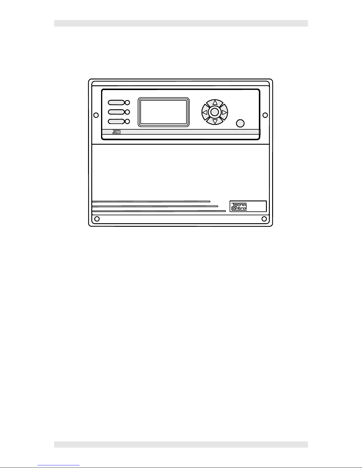
FAULT
ON
ALARM
ESC
ENTER
CITY
Description
The CE400 Central System, designed in a wall mount cabinet 285x230x130mm, is
composed by a front unit for the data processing with keyboard, backlighted graphic display
164x92 pixel, and by a input/output card and power supply. Power supply is 230Vac-50Hz;
the sensors are 20Vcc powerd. The cabinet of the Central System is designed to accept a
12Vcc 7Ah battery to maintain the system powered on in absence of Main power supply.
The CE400 Central System is able to manage up to 4 inputs for 4÷20mA sensors (S1, S2,
S3 ed S4); an auxiliary input for N.O. contacts (AUX) and is able to pilot up to 5 relay output
(AL1, AL2, AL3, AL4 e AUX).
To the Central System can be connected an Expansion Card ES400 to add other 4 inputs
for 4÷20mA sensors (S5, S6, S7 ed S8) and other 4 output relays (AL5, AL6, AL7 e AL8).
• The CE400 Central Unit can be connected to:
- Three-wires linear 4÷20mA transmitters for flammable gases series TS292K (IP65) or
TS293K (Flameprrof) with 0÷20%LIE scale, or series TS293Px (Flameprrof) with
0÷100%LIE scale.
- Two-wires linear 4÷20mA transmittrers, with elettrochemical cell sensors for toxic
gases, series TS220E (IP65) or with with oxygen sensors TS220EO with 0÷25%O2
scale. However the inputs can be set up for any type of detector with a 4÷20 mA signal
functioning with a 20Vcc power supply.
- Devices having a Normally Open contact (sensors with a relay contact, smoke sensors,
Normally Open pushes, etc.) connectable to an auxiliary input (AUX) that activates the
output relay AUX (U9).
• The measurement range of the inputs is divided into the following indications:
Page 4

IST-1400.AA01.02 CE400 “CITY” / User Instructions PAG. 4/21
TECNOCONTROL S.r.l. - Via Miglioli, 97 20090 SEGRATE (MI) - Tel. +39.02.26 92 28 90 - Fax +39.02.21 33 734
FAULT- (<1 mA) - UNDERFLOW (from 1 to 3,5mA) - NORMal (from 3,5 to 21mA), or
PRE1, PRE2, ALLarm, (setup levels) - OVERFLOW (from 21 to 24mA) - FAULT+ (over
the 24mA).
• For each sensor three alarm levels and the fault are available and addressable to
whatever output.
Every output can be configured as follows:
- delay ON up to 250 seconds at the overcoming of the set alarm level.
- delay OFF up to 250 seconds when the input decreases below the set alarm level.
- It can have a time ON for the activation from 0 to 250 seconds, activating for the
selected time and then deactivating only after the selected time has been passed,
whatever the input value is (even if the input remain over the set elerm level).
- It can be memorized (if it has not been set any time ON), so that to stay active even if
the detector that gave the input returns under the alarm level.
- It can be setup with a positive logic (normally activated relay) or with negative logic
(relay in normal position).
• The internal Buzzer can be activated or deactivated in case an AL3 alarm or the AUX
input occur.
• The internal Buzzer emits a “Bip” when keys are pushed.
• Every detector can be Excluded without phisically disconnecting it from the system or
deleting it from the programm. In this case the current value read from the system about
that detector will be showed as well, with the “ “ symbol on the side of the detector
number, but there will be no activity (alarms and outputs) on that value.
• There is also the possibility (and we suggest to always use it) to protect the configuration
settings by a 4 digits “Code” (Password). To modify the Outputs Configuration, Inputs
Configuration, Code or Battery, you will always need to insert the right password.
Page 5
IST-1400.AA01.02 CE400 “CITY” / User Instructions PAG. 5/21
TECNOCONTROL S.r.l. - Via Miglioli, 97 20090 SEGRATE (MI) - Tel. +39.02.26 92 28 90 - Fax +39.02.21 33 734
Central System Monitoring
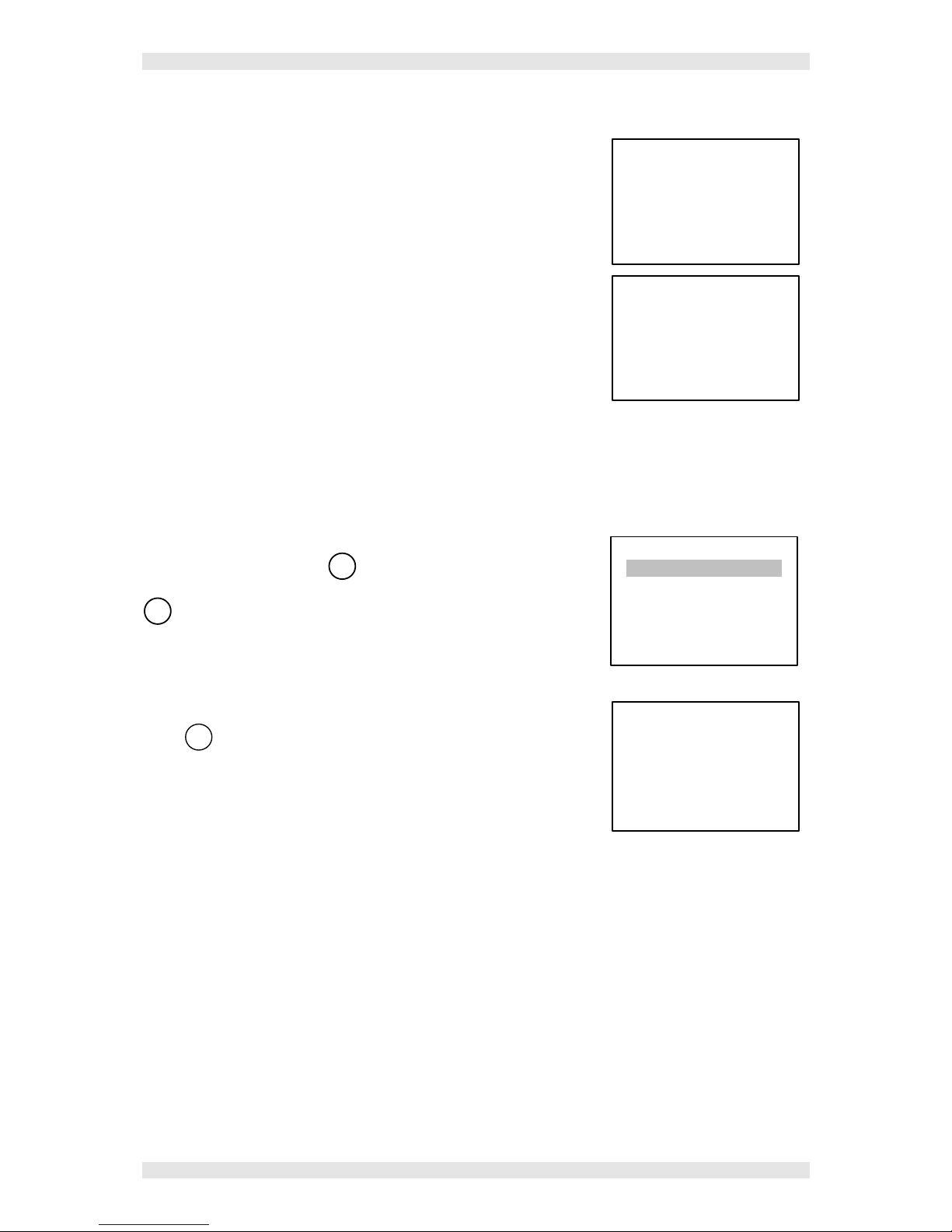
Switching on the Central System, the display will show the following
message for a periond of 30 seconds. This is for stabilize the sensors
and to avoid false alarms. The remaining time is showed by a
contdown.
Than the Central System will show the situation of the connected
detectors. The Display shows all detectors (max 8).
Pay Attention – important Note: detectors inputs are protected against
accidental wire breakings (connection between detectors and Central
System) and against short circuits. If a short circuit occurs, to avoid
damages to the central system or to the sensor, the power supply to that
input is automatically stopped (all others continue to work properly). Simultaneously the yellow LED
“FAULT” lights up and the correspondant relay is activated (if programmed). Only after having solved the
short circuit problem (to test if the channel is no more in short circuit protection you need to mesure if there
is voltage between the terminals “+” and “-“ with a multimeter) it will be possible to restore normal
operational conditions.
Alarms Reset
From the main menu, press
ENTER
to enter into the Select menu.
Select Reset (the cursor should already be in that position) and press
ENTER
to confirm.
The following message appears: Reset done, than it will automatically
appear the Setup Menu.
Press
ESC
to go back to the main menu.
This procedure has to be done to reset the stored relay outputs when
the cause of the alarm has finished.
CITY
Version 1.x
30
1 0 % LEL NORM
2 0 ppm NORM
MAINS ON
Select
Reset
Details
Enabling
Disabling
Miscellaneous
Reset
Done
Page 6
IST-1400.AA01.02 CE400 “CITY” / User Instructions PAG. 6/21
TECNOCONTROL S.r.l. - Via Miglioli, 97 20090 SEGRATE (MI) - Tel. +39.02.26 92 28 90 - Fax +39.02.21 33 734
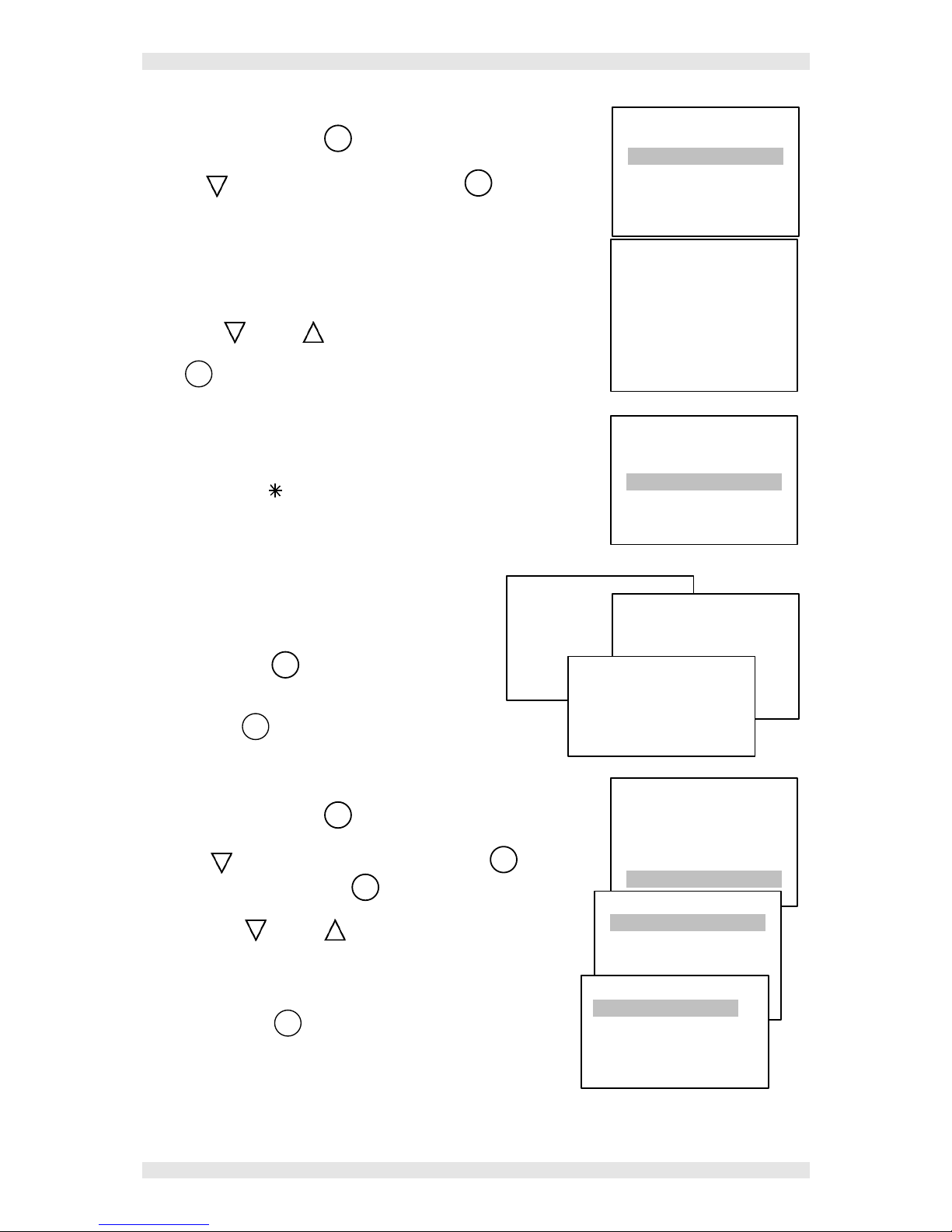
Sensor Details Viewing
From the main menu press
ENTER
to enter into the Select menu.
With the
key select Details and press again
ENTER
,
All settings details about Sensor 1 will appear.
In the 1st line you see the actual sensor status, in the 2nd and 3rd lines
you see the set scale, than you se the values of the alarm levels (L1,
L2, L3), the number of the relay linked to the alarm levels (OUT1,
OUT2, OUT3) and the sensor value in mA.
With down and up keys it is possible to view details of the
other sensors. (If a sensor is not used , it will appear Not Config.).
Press
ESC
to go back to the Setup menu.
Enaling – Disabling Sensors
It is possibile to exclude a sensor without disconnecting it from the
Central System or without deleting it from the programm. In this case
the voltage value read by the central system about that sensor will be
displayed with the symbol on the side of the sensor number but it
will have no effect on the alarms and on the central system outputs.
With the key … select Enable o Disable.
enter the number of the sensor you want to disable
(or to enable).
Pressing the key
ENTER
the following message will
appear for about 2 seconds:
Then, the Setup menu will automatically come back
Press the key
ESC
to exit from the menu and go back to the
main menu.
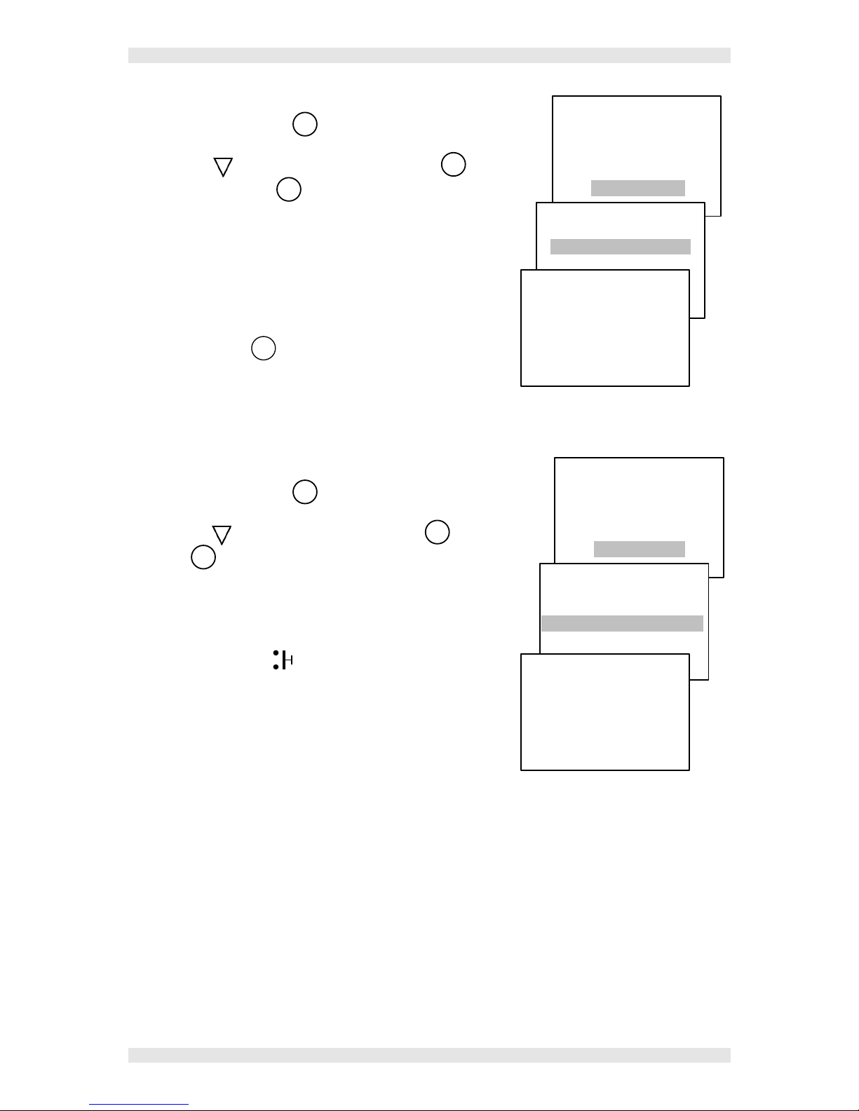
Buzzer Setting
From the main menu press
ENTER
to go to the Select menu.
With the
Key select Miscellaneous and press
ENTER
then select
Buzzer and press again the key
ENTER
.
With the down and up keys, select Buzzer ON or Buzzer
OFF.
Buzzer ON means that in case of alarm both the Red Led and the
internal Buzzer will start. In case of Buzzer OFF the acoustic
alarm will not start.
Press twice the key
ESC
to go back to the Setup menu.
Enabling sensor:
Number: _
Select
Reset
Details
Enable
Disable
Buzzer
Power Supply
Details
1 0 % LEL NORM
Zero= 0.00
Range=100
L1 = 5.00 L2=10.0
L3 = 20.0
OUT1 = 1 OUT2 = 2
OUT3 = 3
I = 4.0 mA
Select
Reset
Details
Enable
Disable
Buzzer
Power Supply
Disabling sensor:
Number: _
Done
Select
Reset
Details
Enable
Disable
Miscellaneous
Miscellaneous
Buzzer
Power Supply
Auxiliary
BUZZER
Buzzer ON
Buzzer OFF
Page 7
IST-1400.AA01.02 CE400 “CITY” / User Instructions PAG. 7/21
TECNOCONTROL S.r.l. - Via Miglioli, 97 20090 SEGRATE (MI) - Tel. +39.02.26 92 28 90 - Fax +39.02.21 33 734
Power Supply datas Viewing
From the main menu press
ENTER
to enter in the Select menu.
With the key
select Miscellaneous and press
ENTER
then select
Power Supply and press
ENTER
again.
Power Supply datas will be displayed. The Battery Voltage will be
showed only if it has been selected as Present. Normally the
value should be around 13,8V. On the contrary, if the battery
has been selected as Absent, the message “Battery not
Installed” will be displayed.
Moreover it is displayed if the Mains is ON or OFF.
Press twice the key
ESC
to go back to the Setup menu.
NOTE: the central system CE400 makes a Battery functional test for a minute each 24 hours only if
the Battey has been selected “Installed”. If the Battery is down or in fault, the yellow Led will start
flashing.
Auxiliary Input status Viewing
From the main menu press
ENTER
to go to the Select menu.
With the key
select Miscellaneous and press
ENTER
select Auxiliary
and press
ENTER
again.
It will be displayed if the auxiliary input is Active or Inactive.
NOTE: when the AUX input is Active, on the main menu it will
appear the symbol
and the AUX (U9) relay will
automatically be activated, even it has been programmed for
another output.
Select
Reset
Details
Enable
Disable
Miscellaneous
Miscellaneous
Buzzer
Power Supply
Auxiliary
Battery
Voltage = 12.5
Mains ON
Select
Reset
Details
Enable
Disable
Miscellaneous
Miscellaneous
Buzzer
Power Supply
Auxiliary
AUX Input
INACTIVE
Page 8

IST-1400.AA01.02 CE400 “CITY” / User Instructions PAG. 8/21
TECNOCONTROL S.r.l. - Via Miglioli, 97 20090 SEGRATE (MI) - Tel. +39.02.26 92 28 90 - Fax +39.02.21 33 734
IMPORTANT REMARK
INSTRUCTIONS CONTAINED IN THE MANUAL BELOW INCLUDE INSTALLATION AND
SYSTEM SETUP PROCEDURES TO BE EXECUTED ONLY BY QUALIFIED AND
AUTHORIZED PEOPLE.
CE400 INSTALLATION
The CE400 is a wall mount central system, it has to be fixed with 3 little blocks in the wall through the
3 holes of the metallic base of the case. We suggest you to mark and fix the central hole first, then
you can mark the other two holes keeping the central system horizontal.
To open the cover of the central system, unscrew the 4 frontal screws. Pay attention in opening the
cover because it is connected with a flat wire to the electronic board fixed on the back side. To easier
install it on the wall, disconnect the flat wire, disconnecting it from the connector. (See Fig.2).
Opening the two tongues on their external side the connector slip automatically out.
To connect it again it is necessary to slip it into the polarized connector to avoid any possibile error,
and push it till when the two tongues will close. Then fix the cover again srewing the 4 screws down.
Fig 1
– Dimensions and wall mounting template
255
95
30
285
130
230
Electrical connections
All electrical connections have to be made in the metallic base of the central system.
Mains Power Supply “230Vac” has to be connected on the power supply terminal “L, N and Ground”
(Fig.4).
The 12V 7Ah Battery (if present) has to be connected to cables “B+” (Red) and “B-” (Black) (Fig.4).
On the cisrcuit placed in the metallic base you can find all terminals for the inputs and outputs
connection. Terminals (Fig.3) have a polarized clutch (1); we suggest to use lugs adequate to the
conductors (2) and to fix the wires to the box structure to avoid excessive stress to the circuits and to
the terminals. Use a screwdriver (3) of the right dimensions.
Connection diagrams showed in Fig.5 e 6, to simplify, are always indicated with all sensors.
Inputs: keep into consideration that the Central System CE400 disposes of 4 inputs 4÷20mA only
(from S1 to S4) and 1 input for Normally Open contacts (AUX). To get other 4 inputs (from S5 to S8),
it is necessary to add the Expansion Card ES400 (On the right of the drawing). Inputs “S1, S2….etc.”
accept any 4-20mA linear current signal, coming from 2-wires or 3-wires transmitters. (See chapter
Sensors Connections). “AUX” input accepts only Normally Open contacts, free from voltage.
Output: The Central System CE400 disposes of all exchange contacts relay outputs free from
voltage. Contacts current carrying capacity is 3A at 250Vac. The Central System CE400 has 5 exits
(AUX and from AL1 to AL4), Expansion Card ES400 has other 4 exits (from AL5 to AL8).
Each relay output contacts are indicated with “C” (common), “NC” (normally closed) and “NA”
(normally open). This indication is referred to relays in “not powered” position, this means normally
deactivated = Negative Logic.
Page 9

IST-1400.AA01.02 CE400 “CITY” / User Instructions PAG. 9/21
TECNOCONTROL S.r.l. - Via Miglioli, 97 20090 SEGRATE (MI) - Tel. +39.02.26 92 28 90 - Fax +39.02.21 33 734
Transformer
S1÷S4 Inputs Terminals
Flat Cable Connector for
cover connection
230 Vca
Terminal
Fig 2 – Internal View CE400 complete of ES400
Wall fixing Holes
U1÷U4 and AUX (U9) Exits
Terminals
ES400
S8
S7
S6 S5
AL8
AL7
AL6
AL5
S1
S2
S3 S4 AUX
AL1
AL2
AL3
AL4
AUX
S5÷S8 Inputs Terminals
U5÷U8 Exit Terminals
Nut and Hanger for
Battery Fixing
AUX Input Terminal
3
1 2
Fig.3 -
Polarized
Clutch Terminals
230V Main Power
Supply Terminal
Fuse 3A
-
+
Rosso / Red /
-Nero / Black
B+ B-
Fig 4 –
Mains Connection
and Battery (Optional)
N
eutral
Ground
L
ine
Battery 12V 7Ah
Page 10

IST-1400.AA01.02 CE400 “CITY” / User Instructions PAG. 10/21
TECNOCONTROL S.r.l. - Via Miglioli, 97 20090 SEGRATE (MI) - Tel. +39.02.26 92 28 90 - Fax +39.02.21 33 734
Fig 5 -
2-wires transmitters series TS210E and TS220E Connection Diagram
AUX
AL1
AL2
AL3
AL4
NC C NA
NC
C NA
NC C NA
NC C NA NC
C NA
+ S -
+ S -
S + -
+ S
- + S -
+ -
S 4
+ -
S 3
+ -
S 2 S 1
+ -
Auxiliary
Input
Terminal
AUX
Expansion Card ES400
AL5
AL6 AL7 AL8
S 8
+ -
+ -
S 5
+ S - + S -
+ S
- + S -
+ -
S 6
S 7
+ -
NC C NA
NC C NA
NC C NA
NC C NA
Fig 6 -
3-wires transmitters series TS210E and TS220E Connection Diagram
AUX
AL1
AL2
AL3
AL4
NC C NA
NC
C NA
NC C NA
NC C NA NC
C NA
+ S -
+ S -
S + -
+ S
- + S -
+ S
S 1
-
+ S
S 2
-
+ S
S 3
-
+ S
S 4
-
Auxiliary
Input
Terminal
AUX
Expansion Card ES400
AL5
AL6
AL7 AL8
+ S - + S -
+ S
- + S -
NC C NA
NC
C NA
NC C NA
NC C NA
+ S
S 8
-
+ S
S 5
-
+ S
S 6
-
+ S
S 7
-
Page 11

IST-1400.AA01.02 CE400 “CITY” / User Instructions PAG. 11/21
TECNOCONTROL S.r.l. - Via Miglioli, 97 20090 SEGRATE (MI) - Tel. +39.02.26 92 28 90 - Fax +39.02.21 33 734
Sensors Connection
Connection of 2-wires 4÷20mA transmitters
Connection of 2-wires 4÷20mA transmitters has to be made (Fig.5) between the “+” and “-” terminals
of the transmitter and the correspondant “+” and “S” terminals of the Central System inputs card.
The section of the connection cables between
sensors and central system has to be calculated in
function of the distance as indicated in the table.
Transmitters series TS210E and TS220E need a
shielded cable. The braiding has to be connected to
the "-" of the input sensor terminal.
Connection of 3-wires 4÷20mA transmitters
Connection of 3-wires 4÷20mA transmitters has to be made (Fig.6) to the “+”, “-” and “S” Terminals of
the transmitter and the correspondant terminals of the Central System inputs card.
The section of the connection cables between
sensors and central system has to be calculated in
function of the distance and the used sensor, as
indicated in the table. Sensors series TS292K,
TS293K and TS293P don’t need shielded cables.
Transmitters Use
PAY ATTENTION: Transmitters calibration is made with calibrated gases, sealed trimmers can be
regulated only by authorized and trained people or by our technicians using calibrated gases.
See the specific Users Instructions of the Treansmitters.
Please note that transmitters series TS292K, TS293K and TS293P for flammable gases, need a
warm-up time, in clean air, for about 20 seconds. After this time they are able to detect gases, but
they reach optimal stability after about 3 hours of continuous work, tests with sample gas should be
done after this time.
Transmitters series TS210E and TS220E reach the optimal stability conditions, in clean air, after
about 1-2 hours of continuous work.
Auxiliary Input and Output AUX
Connection with Normally Open contact devices
Connection to devices (Relay contact detectors, Smoke detectors, Normally Open buttons etc)
disposing of a “not powered” and Normally Open contact, is made (Fig.5) to “S” e “-” terminals of the
AUX input on the Central System.
Auxiliary Power Supply Exit
To the AUX terminal (between “-“ and “+”) it is also available an auxiliary output, about 12Vdc
(11÷16Vcc), for a maximum charge of 12W. Pay attention: we suggest to protect this power supply
with a fuse if the connected device doesn’t have one.
S
+
-
AUX Auxiliary Terminal
Auxiliary Exit
12Vcc / 12W
+
Sensors series TS210E and TS220E
Distance Cable Type
From 0 to 100 meters
3x0,5 mm2 Shielded
From 100 to 200 meters
3x1 mm2 Shielded
From 200 to 500 meters
3x1,5 mm2 Shielded
From 500 to 1000 meters
3x2,5 mm2 Shielded
Sensors series TS292K, TS293K and TS293P
Distance Cable Type
From 0 to 300 meters
3x1.5 mm2
From 300 to 600 meters
3X2.5 mm2
Page 12

IST-1400.AA01.02 CE400 “CITY” / User Instructions PAG. 12/21
TECNOCONTROL S.r.l. - Via Miglioli, 97 20090 SEGRATE (MI) - Tel. +39.02.26 92 28 90 - Fax +39.02.21 33 734
Central System Setup
Keyboard Use and General Informations
The numbers to be changed or entered appear on the display highlighted by the Cursor (flashing
black rectangle). To change or enter a number you can use:
Key
to incease the number (0, 1, 2, 3, 4, 5, 6, 7, 8, 9, . )
Key
to decrease the number (., 9, 8, 7, 6, 5, 4, 3, 2, 1, 0)
Key
to move the curson on the left.
Key
to move the cursor on the right.
Key
ENTER
to confirm.
Key
ESC
to exit.
After having entered the firs sensor setup, the software is configured to propose this setup as the
standard for all others sensors, in this case, if you are entring more sensors with the same setup, all
operations will be much more easy and quick.
Sensors Setup
If no sensors have been already configured, the following message
will be displaied:
Pressing the
ESC
key, you enter in the setup menu.
The cancelled note symbol “
¯
” showed on the bottom right
position of the display shows you that the Buzzer is OFF.
At the start-up configuration you will have access to all functions; but
if you will insert a password code, at the second setup change the
system will ask the access code before entering the setup.
Pressing the key
ENTER
it will appear:
At this point it is necessary to enter the number correspondant to the
input to which the sensor is connected and press
ENTER
to confirm.
Example: if you want to setup sensor n°4, press the key till the
number 4 appears on the display, then press
ENTER
to confirm.
Then, the minimum underflow is displayed, (the Default value is Zero
which is the beginning of the scale).
press key
ENTER
to confirm.
Enter the overflow of the sensor you are setting up (the maximum
selectable value is 9999), (See Appendix Setup 4÷20mA
transmitters Table), then press key
ENTER
to confirm.
Example: if you are setting up a TS293Px, with the keys
you move the cusrsor and with keys and you select the
number 100.0, and then press
ENTER
to confirm.
SETUP
Sensors
Exits
Battery
Code
Sensor setup
Number: _
ZERO : 0.00 _
ZERO : 0.00 _
RANGE: _ _ _ _ _
NO SENSORS
CONFIGURED
Press ESC key to
configure.
Mains ON
¯
Page 13

IST-1400.AA01.02 CE400 “CITY” / User Instructions PAG. 13/21
TECNOCONTROL S.r.l. - Via Miglioli, 97 20090 SEGRATE (MI) - Tel. +39.02.26 92 28 90 - Fax +39.02.21 33 734
Select the sensor measurement unit with key , (ppm, LEL, or %),
then press
ENTER
to confirm.
Example: if you are setting up a TS293Px, select LEL with key ,
then press
ENTER
to confirm.
With the key select if the alarm is Increasing or Decreasing. This
setup defines if alarms will start when the signal from the sensor
increases or decreases (normally you need to select “increasing”, only
for Oxygen it is necessary to choose “Decreasing” to start the alarms
when Oxygen concentration is getting down). Press key
ENTER
to
confirm.
With the key
select the value of the first alarm start (AL1), tehn
press
ENTER
to confirm.
Example: if you are setting up a TS293Px, select the number 6 with
the key , then press
ENTER
to confirm.
NOTE: a value has to be entered.
Select, if required, the number of the relay (from 1 to 8 or number 9 =
AUX) we want to activate at the alarm 1, then press
ENTER
to confirm.
NOTE: this value can be omitted if not necessary.
Select the value of the first alarm start (AL1), then press
ENTER
to
confirm.
Example: if you are setting up a TS293Px, select the number 10
with the key , then press
ENTER
to confirm.
NOTE: a value has to be entered.
Enter, if required, the number of the relay you want to associate to the
second alarm (AL2), then press
ENTER
to confirm.
NOTE: this value can be omitted if not necessary.
Enter the value of the third alarm (AL3), then press
ENTER
to confirm.
Example: if you are setting up a TS293Px, senter the number 20
with the key , then press
ENTER
to confirm.
NOTE: a value has to be entered.
Enter, if required, the number of the relay you want to associate to
the third alarm (AL3), then press
ENTER
to confirm.
NOTE: this value can be omitted if not necessary.
Alarm 1: 6 _ _ _
Exit 1: _ _ _ _
Alarm 1: 6 _ _ _
Exit 1: _ _ _ _
Alarm 2: _ _ _ _
Alarm 1: _ _ _ _ _ _ _
Alarm 1: 6 _ _ _
Exit 1: _ _ _ _
Alarm 2: 10_ _ _
Exit 2: _ _ _ _
Alarm 1: 6 _ _ _
Exit 1: _ _ _ _
Alarm 2: 10_ _ _
Exit 2: _ _ _ _
Alarm 3: _ _ _ _
ZERO : 0.00 _
RANGE: 100.0 _
Unit: ppm
Alarm 1: 6 _ _ _
Exit 1: _ _ _ _
Alarm 2: 10_ _ _
Exit 2: _ _ _ _
Alarm 3: 20_ _ _
Exit 3: _ _ _ _
ZERO : 0.00 _
RANGE : 100.0 _
Unit : LEL
Alarm : Increasing
Page 14

IST-1400.AA01.02 CE400 “CITY” / User Instructions PAG. 14/21
TECNOCONTROL S.r.l. - Via Miglioli, 97 20090 SEGRATE (MI) - Tel. +39.02.26 92 28 90 - Fax +39.02.21 33 734
Enter, if required, the number of the relay you want to use to give
alerm for a fault (Fault), then press
ENTER
to confirm.
NOTE: this value can be omitted if not necessary.
Select “YES” with the key
to confirm all information entered, then
press
ENTER
to confirm; the system will go back to the Setup menu.
Pressing
ESC
you exit from the setup menu. Pressing
ENTER
you can set
a new sensor up.
Delete Sensors
To delete a sensor it is necessary to select it as described in the
previous chapter, then press
ENTER
to scroll all informations entered till
you reach the final question:
Press
ENTER
. Then select “YES” with the key
to dolete all the
informations of the selected sensor, pressing again
ENTER
you confirm
and you go back to the Sensors Setup menu.
Press
ESC
to exit from the setup menu and to go back to the main
menu.
Modifying Sensors Setup
It is possible to modify a sensor already configured in two ways:
If you want simply modify some alarm settings or some outputs you can follow the procedure as for
the sensor setup described in the above paragraph.
If you want to change the sensor type it is recommended to delete first the setup of the sensor you
want to change (See Chapter Delete Sensors), then you can setup the new sensor with the new
configuration.
Confirm ?
NO
YES
Confirm ?
NO
YES
Delete ?
NO
YES
Alarm 1: 6 _ _ _
Exit 1: _ _ _ _
Alarm 2: 10_ _ _
Exit 2: _ _ _ _
Alarm 3: 20_ _ _
Exit 3: _ _ _ _
Fault: _ _
Page 15

IST-1400.AA01.02 CE400 “CITY” / User Instructions PAG. 15/21
TECNOCONTROL S.r.l. - Via Miglioli, 97 20090 SEGRATE (MI) - Tel. +39.02.26 92 28 90 - Fax +39.02.21 33 734
Output Setup
From the Setup menu press to select the Output menu.
Pressing
ENTER
it will appear:
With the key enter the number of the output you want to setup
that corresponds to the relay position on the terminals into the central
system. After having presed
ENTER
to confirm, you go throught the other
parameters. Press directly
ENTER
to skip a parameter that you don’t want
to use or enter the information required and press again
ENTER
to
confirm.
Delay ON: it is the delay time (max 250 seconds) of the output
activation from the moment when the gas concentration overpass the
alarm setting.
Delay OFF: it is the delay time (max 250 seconds) of the output
deactivation from the moment when the gas concentration returns
under the alarm setting.
Time ON: it is the time lenght (max 250 seconds) durino which
the output stay active from the moment when the gas
concentration overpasses the alarm setting. When this time has
elapsed, the output returns to its original status even if the gas
concentration is over the alarm setting
Positive Logic: it indicates if the relay works
normally activated (Positive Logic) or normally
deactivated (Negative Logic). The selection is made selecting
“NO” (Negative) or “YES” (Positive) with key.
Latched Output: it indicates if you want to keep the output
active even if the gas concentration returns under the alarm
setting. Select “NO” or “YES” pressing the key. The
output will need to be manually deactivated by the operator.
Pay attention: this paramenter don’t has to be used if you
have setup a Time ON before, this because there will be a
conflict between the defined output activation time and the
“infinite” time represented by the latched output.
Select “YES” with the key to accept the entered settings. Pressing
the key
ENTER
you confirm and return back to the Sensors Setup menu.
Delay ON : _ _ _
SETUP
Sensors
Output
Battery
Code
SETUP
OUTPUT
Number: _
Delay ON : _ _ _
Delay OFF : _ _ _
Delay ON : _ _ _
Delay OFF : _ _ _
Time ON :_ _ _
Delay ON : _ _ _
Delay OFF : _ _ _
Time ON :_ _ _
POS. Logic : NO
Delay ON : _ _ _
Delay OFF : _ _ _
Time ON :_ _ _
POS: Logic : NO
Latched Output NO:
Confirm ?
NO
YES
Page 16

IST-1400.AA01.02 CE400 “CITY” / User Instructions PAG. 16/21
TECNOCONTROL S.r.l. - Via Miglioli, 97 20090 SEGRATE (MI) - Tel. +39.02.26 92 28 90 - Fax +39.02.21 33 734
Battery Selection
The Central System needs to know if a Battery has been installed ot not.
This information is needed to start the automatic Battery Test Procedure, it is a one minute test and it
is made automatically once a day. If the battery is fault or doesn’t charge correctly, a yello flashing
Led starts lighting.
From the Setup Menu press to select the Battery Menu.
Pressing
ENTER
it will appear:
Select Installed or Not installed with
key. Then press
ENTER
to
confirm.
Code Setup (Password)
The password is an access key that, if entered, protects the system settings from tampering by
unauthorised or unqualified people. In case you want to change the output / input / code / battery
setup, bifore you will have to digit the password correctly.
From the setup Menu press to select the Password Menu.
Pressing
ENTER
it will appear:
Use the keys
and
to digit the Password(max 4 numbers)
then press
ENTER
to confirm. From this point forward all changes will
be protected by a Password.
To delete a Password you have to follow the same procedure as for
create it, but you have to leave the spaces white (all spaces or all
numbers “zero”.
PAY ATTENTION: we suggest to write down and keep the Password in a safety place. In case
you loose the Password get in contact with out technical support.
Backlight
The display will autamaticaaly switch off, when not used, after 30 seconds; pressing any key it light
back again.
SETUP
Sensors
Exits
Battery
Password
New
Password : _ _ _ _
SETUP
Sensors
Exits
Battery
Code
BATTERY
Installed
Not installed
Page 17

IST-1400.AA01.02 CE400 “CITY” / User Instructions PAG. 17/21
TECNOCONTROL S.r.l. - Via Miglioli, 97 20090 SEGRATE (MI) - Tel. +39.02.26 92 28 90 - Fax +39.02.21 33 734
Appendix
List of anomaly messages and Alarms
NO SENSORS CONFIGURED The central system is not configured.
NOT CONFIG. The indicated sensor is not configured.
FAULT- The input signal is less than 1 mA.
The sensor could be faulty, not connected or not powered.
UNDERFLOW The input signal is between 1 and 3,5mA.
The sensor could be out of calibration at the beginning of the scale.
AL1 The alarm 1 value has been exceeded and the related output is active
(if configured).
AL2 The alarm 2 value has been exceeded and the related output is active
(if configured).
AL3 The alarm 3 value has been exceeded and the related output is active
(if configured).
OVERFLOW The input signal is between 21 and 24 mA.
The sensor is detecting gas, but the full scale has been exceeded.
FAULT+ The input signal is bigger than 24 mA.
The sensor could be faulty, or it is detecting gas but it has exceeded
its full scale.
Mains OFF Mains 230Vac power supply is missing.
Battery Not Installed The battery has been setup as not installed.
Display switched off If the greed Led is lighted, the Display could be damaged or the
contrast is too low, try to regulate it with the trimmer on the Board:
(“Contrast ADJ” bottom right corner) placed in the front cover of the
central system.
List of Acoustic and Optical Signals
Intermittent Buzzer One of the sensors has exceeded the alarm 3 level (AL3) or
the AUX input is active.
Symbol
¯
If on the display appears the symbol of the “cancelled Note”
(bottom right corner), it means that the Buzzer is Deactivated.
Green Led Continuosly on Mains power supply ON.
Green Led Blinking Powered by Battery; the Mains is OFF.
Red Led on One of the sensors has exceeded the alarm 3 level (AL3).
Red Led Blinking One of the sensors has exceeded the alarm 1 and 2 levels
(AL1 and AL2); or one of the Latched Output relay has been
activated.
Yellow Led Blinking Battery is fault (Voltage less than 10 Vdc).
Yellow Led on One of the sensors is FAULT+ or FAULT-.
Symbol
If on the Display appears the symbol of the “Button” (bottom
right corner); it means that AUX input and output (U) are
active.
Green Led and Display OFF Mains power supply OFF, and battery has powered the
central system till it got down. If the battery voltage get down
under 10,8 Volts, it is automatically disconnected to avoid
damages.
Page 18

IST-1400.AA01.02 CE400 “CITY” / User Instructions PAG. 18/21
TECNOCONTROL S.r.l. - Via Miglioli, 97 20090 SEGRATE (MI) - Tel. +39.02.26 92 28 90 - Fax +39.02.21 33 734
Operations Check “Test”
The CE400 Central System is equipped with a Test Program that allows the test of all central system
operations and functionalities.
PAY ATTENTION: This procedure has to be made with estreme attention and by
authorized and trained people; because starting this procedure it will start both
Outputs (relays) causing the activation of connected alarm devices and the internal
functions of the central system.
To enter into the Test Program it is necessary to disconnect the battery (if installed) and to switch off
the central system cutting the Mains voltage.
Ower on the central system pressing the key
ENTER
within 3 seconds, it
will appear:
Input Test (Sensors)
Press the key
to select Inputs. Then press
ENTER
to confirm.
All sensors values will appear, even the non configured sensors and
the sensors of the Expansion Card ES400 (from n° 5 to n° 8). The
first value is a digital control number* (0÷1024), the second is the
mA sensors value read from the central system.
* = number 0000 corresponds to 0.0mA and number 1024 to 25mA
Output test
Press
ESC
to go back to the Test Menu. Press
to select Outputs.
Then press
ENTER
to confirm.
From this point it starts a Test sequence that allows to activate (ON)
and deactivate (OFF) all the installed Outputs relays.
With the
ENTER
key you can cheange between OFF and ON and
vice versa.
The key
is used to select the next test.
OUTPUT 1 = Relay 1 (AL1)
OUTPUT 2 = Relay 2 (AL2)
OUTPUT 3 = Relay 3 (AL3)
OUTPUT 4 = Relay 4 (AL4)
If a card ES400 is installed, it is possible to make the test of
outputs from n° 5 to n° 8, on the contrary press till ythe
AUX output.
OUTPUT 5 = Relay 5 (AL5)
OUTPUT 6 = Relay 6 (AL6)
OUTPUT 7 = Relay 7 (AL7)
OUTPUT 8 = Relay 8 (AL8)
OUTPUT AUX = Relay 9 (AUX)
TEST
Inputs
Outputs
Auxiliary
Power Supply
1: 0164 -> 4.0 mA
2: 0184 -> 4.5 mA
3: 0172 -> 4.2 mA
4: 0160 -> 3.9 mA
5: 0000 -> 0.0 mA
6: 0000 -> 0.0 mA
7: 0000 -> 0.0 mA
8: 0000 -> 0.0 mA
TEST
Inputs
Outputs
Auxiliary
Alimentazione
Output Test
Output 1 OFF
Output Test
Output 2 OFF
Output Test
Output 3 OFF
Output Test
Output 4 OFF
Output Test
Output 5 OFF
Output Test
Output 6 OFF
Output Test
Output 7 OFF
Output Test
Output 8 OFF
Output Test
Output AUX OFF
Page 19

IST-1400.AA01.02 CE400 “CITY” / User Instructions PAG. 19/21
TECNOCONTROL S.r.l. - Via Miglioli, 97 20090 SEGRATE (MI) - Tel. +39.02.26 92 28 90 - Fax +39.02.21 33 734
From this point it starts a Test sequence that allows you to activate
(ON) and deactivate (OFF) the internal functions of the central system.
Red LED
Yellow LED
Green LED
BUZZER
Display LIGHT
Battery TEST
We suggest to skip this test because it doesn’t give you visible
informations, in fact, it has been made for internal use
during the device test.
Auxiliary Input Test
Press
ESC
to go back to he Test Menu. Press the key
to select
Power Supply. Then press
ENTER
to confirm
.
The input will be showed as INACTIVE, closing the AUX input with
a “bridge” (between “S” and “-“) it will be showed ACTIVE.
Press
ESC
to go back to the Test Menu.
Battery / Mains Test
Press
ESC
to go back to the Test Menu. Press the key
to select
Power Supply. Then press
ENTER
to confirm.
If the Battery is connected and it is charged, it will appear the
value of about 13,8 V
If the Battery is not connected or not present, this value will be
about 3,5V.
Press
ESC
to go back to the Test Menu, press again
ESC
and select
YES with the key
, press
ESC
to start again the normal fuctioning
of the central system.
TEST
Inputs
Outputs
Auxiliary
Battery / Mains
Battery
Voltage = 0.00 V
Mains ON
Output Test
Red LED OFF
Output Test
Yellow LED OFF
Output Test
Green LED OFF
Output Test
Buzzer OFF
Output Test
Display light OFF
Output Test
Battery Test OFF
Confirm ?
NO
YES
TEST
Inputs
Outputs
Auxiliary
Battery / Mains
AUX Input
INACTIVE
Page 20

IST-1400.AA01.02 CE400 “CITY” / User Instructions PAG. 20/21
TECNOCONTROL S.r.l. - Via Miglioli, 97 20090 SEGRATE (MI) - Tel. +39.02.26 92 28 90 - Fax +39.02.21 33 734
Technical Characteristics
Technical Characteristics central system Mod. CE400
Main Power Supply 230 Vac (-15/+10%) - 50 Hz (±10%)
Minimum absorbed power at 230V 4VA without Sensors connected
Maximum absorbed power at 230V 12VA with 4 Sensors series TS293P
(*)
Maximum absorbed power at 230V
18VA with 8 Sensors series TS293P
Inputs 4 analogic Linear 4÷20 mA (Max. scale 0÷9999)
1 ON/OFF active if Normally Closed
Internal Resistence of inputs charge 200 ohm
Input power supply (Sensors) 20 Vcc (–10/+15%)
Output 5 relays with Voltage free exchange contacts
Relay Capacity 3A (1A) - 230 Vac
Working Temperature with Battery +5 ÷ +40 °C
Buffer Battery (on demand) 12 Vcc - 7 Ah (152 x 65 x 94mm)
Battery Life about 6 hours with 4 Sensors (Series TS293P)
(*)
about 4 ore at full charge (8 sensors seriesTS293P)
Display Backlighted Graphic LCD
Keyboard 6 membrane keys
Dimensions (L x H x W) 285 x 230 x 130mm
Weight About 3 Kg
Technical Characteristics Expansion Card IN/OUT mod. ES400 (*)
Inputs 4 analogic Linear 4÷20 mA
Internal Resistence of inputs charge 200 ohm
Input power supply (Sensors) 20 Vcc (–10/+15%)
Output 4 relays with Voltage free exchange contacts
Relay Capacity 3A (1A) - 230 Vac
Configurable 4÷20 mA TRANSMITTERS Table
Suggested Alarm Levelsi
MODEL GAS Zero
Value
Full
Scale
Unit AL1
(2)
AL2 AL3
TS220EA
NH3 0 300 ppm
10
(3)
20 50÷100
TS220EC
CO 0 300 ppm
25
(2)
÷50
100 200
TS220EH
H2S 0 100 ppm 10 20 50
TS220EO
O2 0 25 %
18,5
(3) (4)
19.5
(4)
22
TS220ES
SO2 0 100 ppm 10 20 50
TS292KG
GPL 0 20 %LIE
7
(3)
10 20
TS292KM
METHAN 0 20 %LIE
6
(3)
10 20
TS293KG
LPG 0 20 %LIE
7
(3)
10 20
TS293KM
METHAN 0 20 %LIE
6
(3)
10 20
TS293Px
(1)
EXPLOSIVE
0 100 %LIE
7
(3)
10÷15 20÷30
(1)
All TS293P series sensors are calibrated with Full Scale 100%LEL, only the calibration gas
changes.
(2)
If required.
(3)
We suggest to set lower alarm levels.
(4)
Adecreasing Alarm.
Page 21

IST-1400.AA01.02 CE400 “CITY” / User Instructions PAG. 21/21
TECNOCONTROL S.r.l. - Via Miglioli, 97 20090 SEGRATE (MI) - Tel. +39.02.26 92 28 90 - Fax +39.02.21 33 734
Setup Memorandum Tables
We suggest to fill in these tables as a memorandum of the configuration you set up. Moreover it will be
better to make a copy of these datas, adding it to the central system (Eliminating the section “Code”) and
another complete copy to the central system documentation.
Sensors Setup
CE400 + ES400
Sensor Number S1 S2 S3 S4 S5 S6 S7 S8
Sensor Model
Zero Value (Normal = 0)
Full Scale
Unit (ppm, LIE o %)
Alarm (Increasing or
Decreasing for Oxygen)
Level 1 (AL 1)
Output 1 (Number of Relay)
Level 2 (AL 2)
Output 2 (Number of Relay)
Level 3 (AL3)
Output 3 (Number of Relay)
Fault (Number of Relay)
Output Setup
CE400 + ES400
Output (Relay) Number U1 U2 U3 U4 AUX(U9) U5 U6 U7 U8
Delay ON (in Seconds)
Delay OFF (in Seconds)
Time ON (in Seconds)
Positive Logic (NO/YES)
Latched Output (NO/YES)
NOTE:
#--------------------------------------------------------------------------------------------------------------------------------
CODE (Password)
Installation Date. Serial Number
PAY ATTENTION: we suggest to write down and store the code (max. 4 numbers)
in a safety place. In case the Code get lost, contact our Service
Dept. That will give an emergency Code.
 Loading...