

Tecnocontrol Beta SE330K, Beta SE333K Series, Beta SE330KM, Beta SE330KG, Beta SE333KM Series Manual
...
GAS LEAK DETECTOR FOR DOMESTIC USE WITH
INTERCHANGEABLE SENSOR
at a maximum distance of 30 cm from the ceiling; in the case of Beta
SE330KG and Beta SE333KG LPG gas detectors, at a maximum height of
30 cm above the floor.
- At a distance of between 1 and 4 metres from the gas appliance (cooker,
boiler, etc.). If possible, in every room where there is a gas appliance and,
in the case of multi-storey buildings, at least one on each floor.
series Beta model SE330K
series Beta model SE333K
Model Detected gas Logic Power supply
SE330KM Methane Neg.
SE330KG L.P.G. Neg.
SE333KM Methane Pos.
SE333KG L.P.G. Pos.
Sensor module
Code
ZSDM1 METHANE SE330KM/SE333KM
ZSDG1
Detected gas
L.P.G. SE330KG/SE333KG
GENERAL DESCRIPTION
The Beta SE330K and SE333K gas detectors are methane or LPG control
units with LEDs and a buzzer that warn of the presence of gas in the
room. They are designed to be operated either directly or in remote mode.
The Beta detectors are calibrated to detect gas at 10% of the LEL (Lower
Explosive Limit); this threshold can vary according to environmental
conditions but will not exceed 15% of the LEL within the first five years of
use. The Sensor module must be replaced at the end of these five years or
if the “FAULT” LED turns on.
There is a label on the cover that should state the expiry date (5 years
after the date of installation); this label must be compiled by the person
who installs the detector, at the time of installation.
LEDS AND BUZZER
There are three LEDs on the front of each detector:
230Vac 50Hz /
12Vdc
Beta
30cm
max
1-4m
Methane gas
detector
The instrument MUST NOT BE INSTALLED:
- Directly above the sink or gas appliance.
- In small rooms where alcohol, ammonia, spray cylinders or other
substances based on volatile solvents might be used.
- In closed environments or corners where there is no free circulation of
air.
- Near walls or other obstacles that could prevent the flow of gas from the
appliance to the detector, or extractors and fans that could divert the flow
of air.
- In environments where the temperature could exceed 40°C or fall below
– 5°C.
1-4m
30cm
max
L.P.G. gas
detector.
INSTALLATION INSTRUCTIONS
Use a screwdriver to undo the screw on the right-hand side of the
instrument and lift the cover (Fig 1).
Fig.1
Position the base correctly and fasten it on the built-in 3-module box or on
the wall, using the screws and dowels provided.
ELECTRICAL CONNECTION: POWER SUPPLY
Attention: undertrack cables are required to connect the instrument to the
mains.
The gas detector must be powered at 230 Vac using terminals 1 and 2, or
at 12Vdc using terminals 3 (+) and 4 (-). (Fig. 2).
- GREEN LED (ON): indicates the instrument is powered.
- YELLOW LED (FAULT) + BUZZER: Indicates the sensor is broken.
- YELLOW LED (FAULT) blinking only: indicates the CO sensor
needs to be replaced.
- RED LED (ALARM): indicates the concentration of gas in the
air is above the alarm threshold.
If the gas sensor is defective, the buzzer will make a noise at a rate of
every two seconds, turning on the yellow LED and relay output.
In the event of an alarm, the red LED turns on and the buzzer and relay are
activated twenty seconds later.
LIGHTING DELAYS
After the detector is turned on, the catalytic sensor in the detector takes
about a minute to warm up, during which time the green LED blinks to
indicate the alarm is disabled.
INSTALLATION
Attention: the instrument must be installed and put out of service by a
specialized technician.
Your gas supply and any shut-off devices must be installed in conformity
with the domestic laws in force.
INSTALLING THE INSTRUMENT
The instrument MUST BE INSTALLED:
- In the case of Beta SE330KM and Beta SE333KM methane gas detectors,
1 2
3
4
+ -
Fig.2
A circuit breaker must be fitted that is able to disconnect the detector from
the power supply, with a contact distance of at least 3 mm, in accordance
with the European standard IEC EN 60335-1.
230Vac
CHARACTERISTICS OF THE OUTPUT SIGNAL
The Beta SE330K and SE333K control units have an output relay with
voltage-free contacts; the rating of the contacts is 8A 250Vac/30Vdc.
GENERAL TERMS OF THE GUARANTEE
THIS CERTIFICATE IS THE ONLY DOCUMENT THAT ENTITLES
YOU TO REPAIR OF THE PRODUCT UNDER THE TERMS OF
- The product is GUARANTEED for a period of 24 months from the date
of purchase.
- The GUARANTEE does not cover damage caused by tampering,
incorrect or improper use and installation.
- The GUARANTEE is valid only if it is duly compiled.
- In the event of defects covered by the GUARANTEE, the manufacturer
will repair or substitute the product free of charge.
SERVICING AFTER THE GUARANTEE PERIOD:
Any repairs after the period of the GUARANTEE will be charged on the
basis of the parts substituted and the cost of labour.
12Vdc
THE GUARANTEE.
CONNECTION OF THE ELECTRIC VALVE AND
NA C NC
R R
+ -
1 2 3
5 4 6 7 8 9
N
A C N
C
R R + -
1 2 3
5 4 6 7 8 9
N
A C N
C
R R
+ -
1 2 3
5 4 6 7 8 9
NA C NC R R + -
1 2 3 5 4 6 7 8 9
NA C NC R R + -
1 2 3 5 4 6 7 8 9
REMOTE SENSORS
The Beta SE330K and SE333K control units each have two terminals (5-
6) active when closed, for connecting the following remote detectors (Fig. 3):
for METHANE gas: model SE195KM or model SE396KM.
for LPG gas: model SE195KG or model SE306KG.
If the remote sensors are not connected to terminals 5 and 6, these must
not be modified, and therefore kept disconnected at all times.
Do not forget that the electric valve must be installed on the gas pipe
outside the room to be controlled as it cannot protect against leaks upstream.
The Beta SE330/SE333 + Beta SE330/SE333 configuration is IMQ
certified.
The other configurations, Beta SE330/SE333 + SE195 K and Beta SE330/
SE333 + SE396K are not IMQ certified.
SE330K SE396K
N.O. manual
230Vac - 50Hz 230Vac - 50Hz
Fig. 3 Example of connection of a remote sensor.
The Beta SE396K detector is not IMQ certified but complies fully with
standard IEC UNI EN 50194.
reset valve
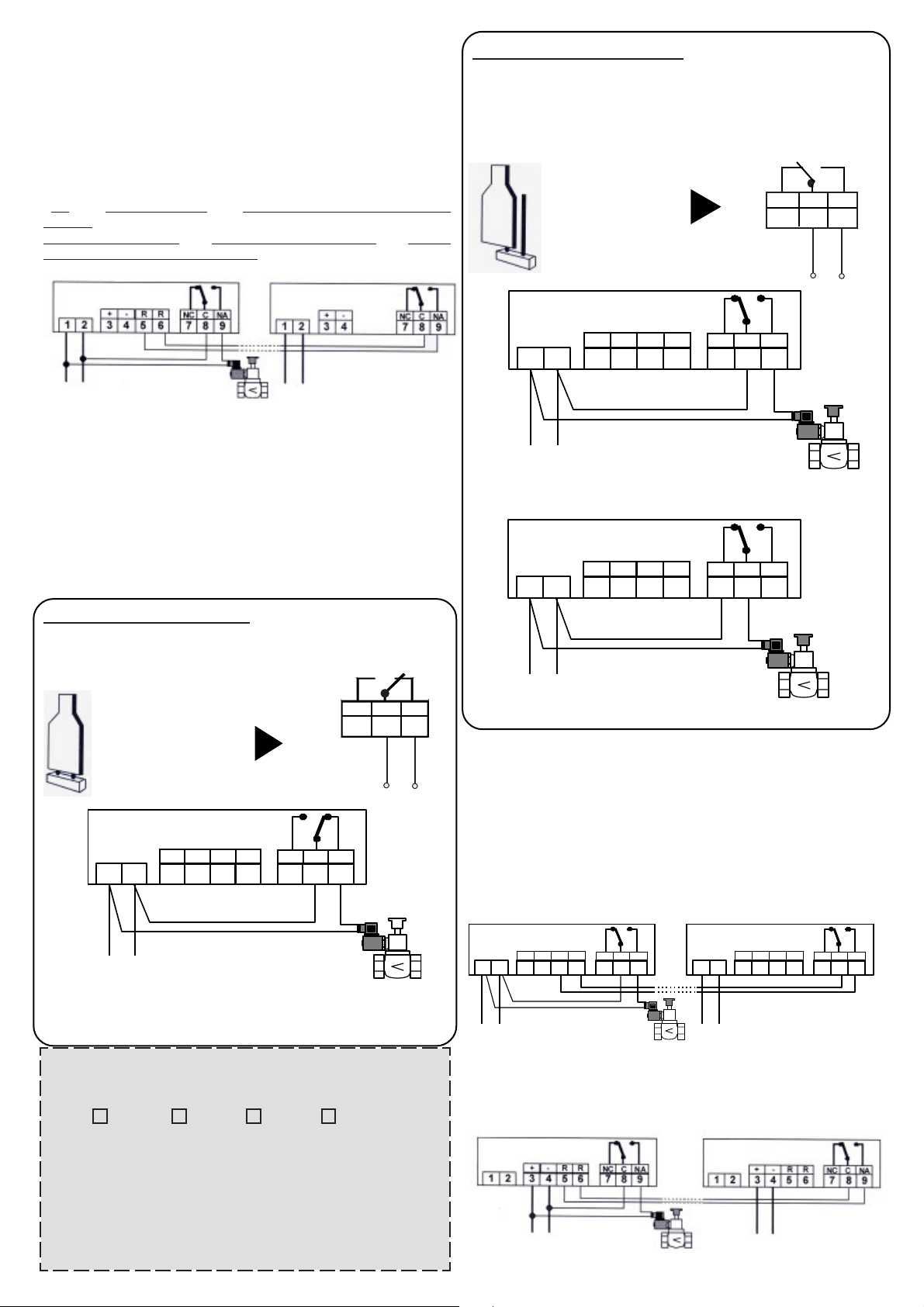
POSITIVE LOGIC – NEGATIVE LOGIC
The Beta SE330K and SE333K gas detector can control an electric valve
using two different logics:
1 – POSITIVE LOGIC (SE333K)
2 – NEGATIVE LOGIC (SE330K)
The J2 JUMPER allows you to select the one required.
N.B. The J2 JUMPER is set by default to NEGATIVE LOGIC (SE330K).
NEGATIVE LOGIC (SE330K): in this case, the coil of the relay is
kept deactivated (Fig. 6).
It is perfect for N.O. (normally open) electric valves (Fig. 7) or N.C.
(normally closed) electric valves (Fig. 8).
In the event of an alarm, contacts 8 and 9 remain closed until the
alarm stops.
230Vac/50Hz
Fig.7
J2 JUMPER IN
“NEGATIVE LOGIC”
POSITION
SE330K
Normally open
SE330K
NC C NA
7 8 9
Fig.6
EV
POSITIVE LOGIC (SE333K): in this case, the coil of the relay is
always live (Fig. 4) to ensure the inherent safety of the relay.
It is perfect for N.C. (normally closed) electric valves (Fig. 5).
In the event of an alarm, contacts 7 and 8 remain closed until the
alarm stops.
NA C NC
J2 JUMPER IN
“POSITIVE LOGIC”
POSITION
EXAMPLE OF APPLICATION WITH N.C. ELECTRIC VALVE SE333
SE333K
EV
Fig.5
230Vac/50Hz
ATTENTION: If there is a temporary loss of power during operation with
positive logic, the N.C. valve closes automatically and will need to be reset
manually when power is restored.
Normally close
7 8 9
Fig.4
EV
Normally close
230Vac/50Hz
Fig.8
ELECTRICAL CONNECTION WITH SEVERAL
DETECTORS:
Connection of two detectors with a single electric valve is shown in the
diagrams below. It is possible to connect more than two detectors, repeating
the same connections.
SE330K
Connection with Normally Open manual reset electric valve (with relay
normally deactivated) and a second SE330K detector.
SE330K SE330K
230Vac 50Hz 230Vac 50HzNO GAS GAS EV
GUARANTEE CERTIFICATE
TO COMPILE AND SEND IN CASE OF DAMAGE
DEVICE: SE330KM SE330KG SE333KM SE333KG
Serial number (s.n.)_________________________________________
DEALER
Stamp: Date of purchase:
USER
Surname and name _________________________________________
Address _____________________________________ n°__________
Postcode ________________ Town/city ________________________
Telephone_________________________________________________
_____/_____/_____
Connection with 12 Vdc Normally Open manual reset electric valve (with
relay normally deactivated) and a second SE330K detector.
SE330K
12Vdc 12Vdc
NO GAS GAS EV 12Vdc
SE330K
 Loading...