

Tecnoclima SR-UT 86, SR-UT 106, SR-UT/K 26, SR-UT/K 36, SR-UT 36 Technical Information Assembly, Use And Maintenance Instructions
...
TECHNICAL INFORMATION
ASSEMBLY, USE AND MAINTENANCE INSTRUCTIONS
HEATING UNITS
WITH ATMOSPHERIC BURNER
SERIE SR-UT SR-UT/K
1.0
Manual attached to the USE AND MAINTENANCE INSTRUCTIONS of the UT and UT/K series
As to what is not expressly mentioned in this manual, it is valid what is set forth in the manual ASSEMBLY USE AND
MAINTENANCE INSTRUCTIONS of the UT and UT/K series appliances
1

GENERAL INFORMATION
COMPLIANCE AND PIN NUMBER
PRODUCT RANGE
WARRANTY
GENERAL WARNINGS
BASIC SAFETY RULES
DISPOSAL INSTRUCTIONS
Dear Customer,
Thank you for choosing a TECNOCLIMA product.
This instruction handbook includes instructions and suggestions that shall be complied with for simpler
2.0
installation and to ensure the best use of the appliance.
Thank you.
Tecnoclima S.p.A.
3.0
The machine complies with the Directives, Rules and Regulations listed in the Declaration of Conformity that
can be requested to the Producer. The PIN number of the EC certification, if any, is included in the technical
data plate.
Throughout this manual, reference is made to the TYPE, to which the TRADE NAME specified in the table is
connected:
4.0
TRADE NAME TYPE TRADE NAME TYPE
SR-UT 26 1 SR-UT/K 26 7
SR-UT 36 2 SR-UT/K 36 8
SR-UT 46 3 SR-UT/K 46 9
SR-UT 66 4 SR-UT/K 66 10
SR-UT 86 5 SR-UT/K 86 11
SR-UT 106 6 SR-UT/K 106 12
5.0
The appliance is covered by a specific warranty, whose terms are specified in detail in the warranty
certificate or in the delivery contract, which should be read with great care.
6.0
As for general warnings, refer to the user’s manual of the UT and UT/K series.
Any operation on the appliance shall be performed only by qualified and skilled workers.
7.0
As for basic safety rules, please refer to the user’s manual of the series UT and UT/K
8.0
The appliance contains electric components; therefore it shall not be disposed of as household waste. As for
disposal methods, refer to the local laws on special waste.
2
GENERAL INFORMATION
DESCRIPTION
STRUCTURE
2
1
4
6
5
3
7
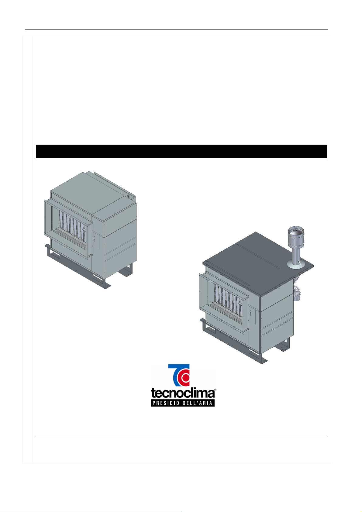
These machines are heating units to be used for air heating. They are essentially thermal units of exchange
between the combustion products of an atmospheric burner and the air flow generated by a ventilation unit
not included in the scope of supply. The air to be heated is sucked by the ventilation unit and, when it laps
the hot surface of the heat exchanger, it is heated - increasing its temperature; then it can be distributed
both directly and through proper channels. Trough this heating system, the plant costs can be remarkably
reduced and a reliable operating economy can be reached.
9.0
WARNING
!
The heating sections type 1-2-3-4-5-6 are designed to be installed indoors, and protected from atmospheric
agents.
Heating units type 7-8-9-10-11-12 have been conceived to be installed outdoors.
10.0
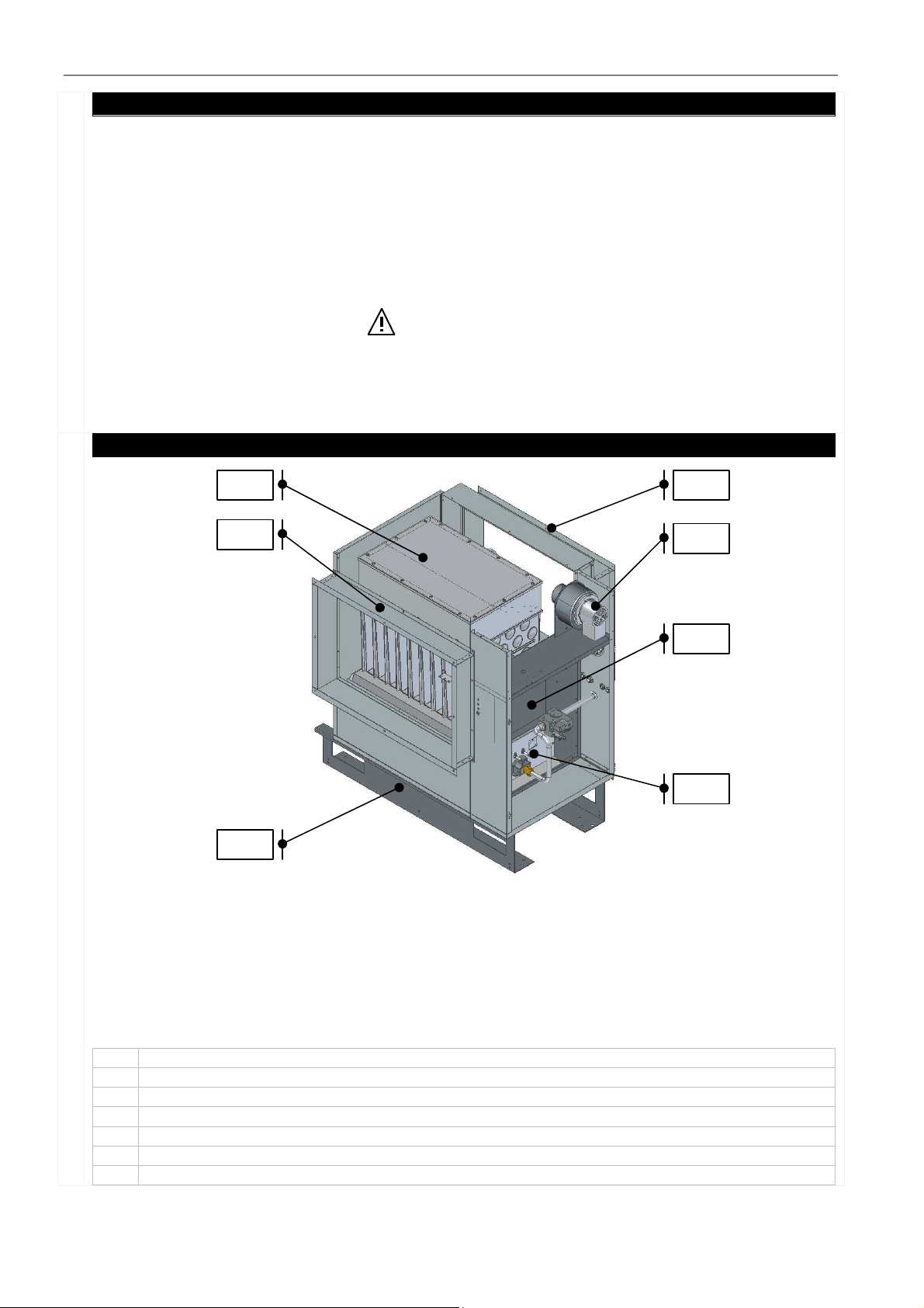
Legend of the components:
1. Air inlet flange
2. Smoke exhaust
3. Electric panel
4. Atmospheric burner
5. Lower frame
6. Air outlet flange
7. Heat exchanger
3
GENERAL INFORMATION
VOLUME AND WEIGHT
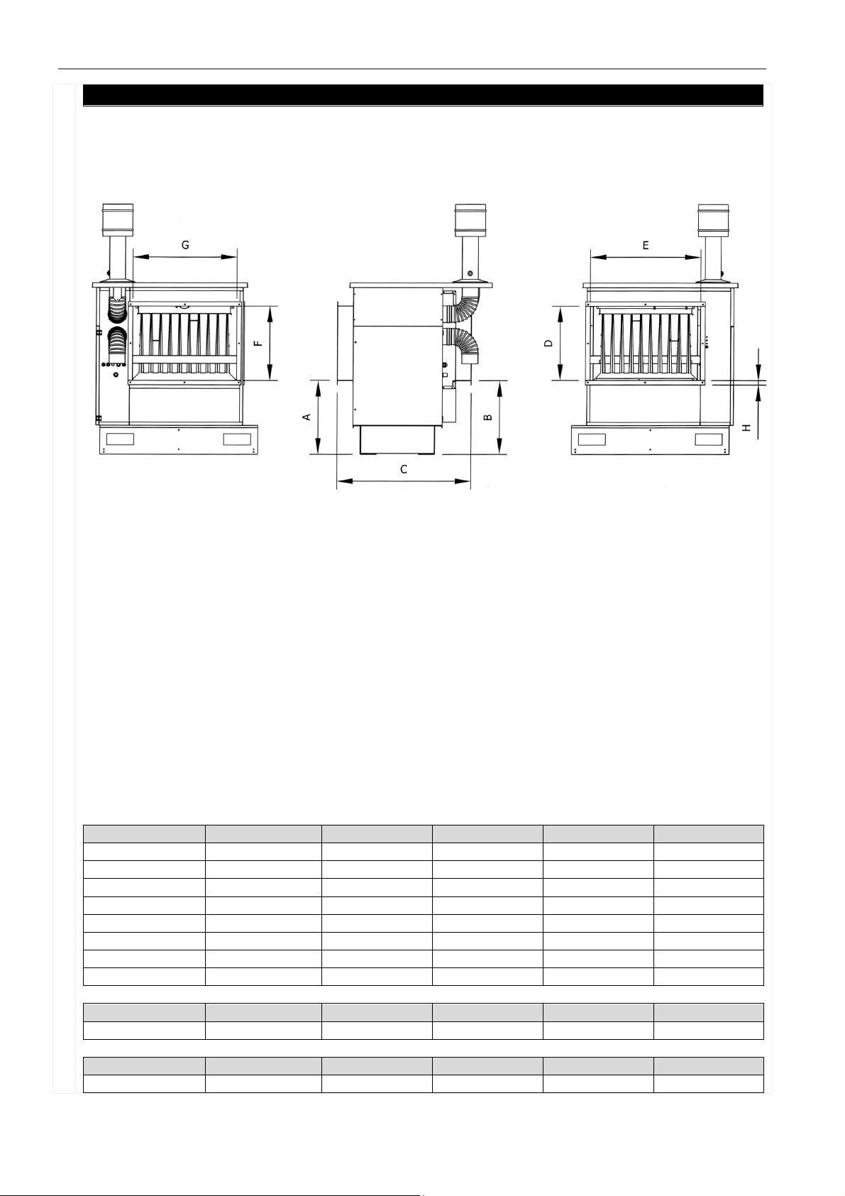
TYPE 1-2-3-4-7-8-9-10:
(This drawing represents the outdoor installation design)
11.0
TYPE 1-7 2-8 3-9 4-10
A mm 460 460 460 460
B mm 460 460 460 460
C mm 840 840 840 ?
D mm 464 464 464 464
E mm 435 515 695 940
F mm 464 464 464 464
G mm 350 460 655 900
H mm 27 27 27 27
TYPE 1 2 3 4
Net weight kg 95 105 130 155
TYPE 7 8 9 10
Net weight kg 105 115 140 170
4

INSTALLATION AND SETTING INSTRUCTIONS
VOLUME AND WEIGHT
Type 5-6-11-12:
(This drawing represents the outdoor installation design)
11.0
TYPE 5-11 6-12
A mm 460 460
B mm 460 460
C mm 895 895
D mm 464 464
E mm 1300 1540
F mm 464 464
G mm 1260 1500
H mm 27 27
TYPE 5 6
Net weight kg 235 260
TIPO 11 12
Net weight kg 260 290
5

INSTALLATION AND SETTING INSTRUCTIONS
SPECIFIC TECHNICAL DATA
1
STOP
LOCATION
RESPECT AREA
TYPE 1-7 2-8 3-9 4-10 5-11 6-12
ELECTRIC SUPPLY
MINIMUM AIR FLOW
m³/h 1.820 2.920 4.130 5.900 7.900 8.750
Single-phase
230V∼50Hz Three-phase 400V∼50Hz 3N
USE LIMITS
12.0
max. pressure Pa +500
installation temperature °C -15/+40
suctioned air temperature °C -15/+30
1) Air flow shall be guaranteed by the Installer. Should a different air flow be required, please contact
the Manufacturer.
Do not stop the machine by disconnecting it from the power supply, since the thermal
25.0
energy stored in the heat exchanger could dangerously overheat it, damaging the warm air
heater. Moreover the LIMIT thermostat could be triggered and it might be necessary to
manually unblock it.
The installation place must be chosen by the plant designer or by a person competent in this matter; this
place must meet the requirements specified by the Standards and Regulations in force; generally, special
authorisations are to be obtained (e.g. town-planning, architectural, fire-fighting, environmental regulations
etc.)
Therefore, before installing the appliance, it is advisable to request and obtain the necessary authorisations.
We suggest not to install the machine:
26.0
• in places with aggressive atmosphere;
• in narrow places where the heater noise level can be magnified by reverberation and resonance;
• in corners where leaves can deposit or any other materials might obstruct the air opening, thus
decreasing the heater efficiency;
• in pressurised areas;
• in depressurised areas;
• outdoors, if not provided with a protection against bad weather conditions (if they are not machines
adequately conceived for such use).
The machine shall be easily and safely reached without needing special equipment (ladders movable platforms -etc.). Around the machine, minimum distances shall be complied with so that the
27.0
control and/or maintenance operations can be performed and that no obstacles block the air flow.
Any law or specific regulations (e.g. fire prevention) shall be complied with. Consult the plant
designer.
6

INSTALLATION AND SETTING INSTRUCTIONS
CONNECTION
SAFETY FL
OW GAUGE
TREATED AIR SUCTION
– OUTLET DIRECTION
ORIGINAL ACCESSORIES
CONDENSATION CHECK
28.0
The electric and hydraulic connection is to be carried out in compliance with all the relevant Regulations and
they should not be a hinder to the machine.
To guarantee a correct machine operation it is required to install on the plant a device (e.g. air gauge)
breaking burner operation in the event that air flow decreases beyond the minimum value set forth in
section SPECIFIC TECHNICAL DATA.
29.0
IN Direction – suction direction of air to be treated
OUT Direction – suction direction of treated air
30.0
To install the accessories, follow the instructions included in the relevant package.
The appliance is designed to be operated with the heating capacity and the air flow rate specified in the
Data Sheet chapter. If the heating capacity is too low and/or the air flow rate is too high, combustion
products may condensate, resulting in the irreparable corrosion of the heat exchanger. If the heating
capacity is too high and/or the air flow rate is too low, an anomalous overheating of the heat exchanger
37.0
may occur, resulting in the activation of the safety devices and causing damage to the exchanger.
It has to be checked if condensation is forming inside the heat exchanger during its
functioning. This check should be performed by turning off the burner after half an hour
of continuous functioning, checking if there is any trace of humidity in the exhaust
manifold.
7

INSTALLATION AND SETTING INSTRUCTIONS
TRANSFORMATION GAS / FORCED GAS BURNER
ELECTRIC CONNECTION
Burners are factory-configured for operation with natural gas G20. The transformation, if required, to
another type of fuel gas is installer’s responsibility and charge. Such transformation may be carried out only
38.0
by qualified and skilled workers strictly observing the specifications set forth in the instruction manuals of
the burner and of the power ramp, if any, provided together with them.
Electrical connections should be made by qualified personnel and in compliance with the relevant
Regulations, using the
ad hoc
terminals. For any electrical operation to be performed, refer to the wiring
diagram included in this manual and provided together with the appliance.
• Install a circuit breaker of the size required by the relevant regulations before the machine.
• Always connect the earth connection of the machine, leaving the earth wire slightly longer than the
line wires, so that, should they be accidentally torn off, it will be the last to be detached.
• Have authorized personnel check that the wire sections and the electric plant are adequate for the
40.0
max. absorbed power specified in the plate data.
• Take into account the polarity in the power supply connection (phase - neutral).
• The machine should compulsorily be connected to an effective earthing system. The Producer shall
not be held liable for damage occurred because the machine is not equipped with an earth
connection.
• Electrical wires should be placed so as not to come into contact with hot and/or cold surfaces or
with cutting edges.
• In compliance with the electric Regulations concerning the installation, install a device ensuring that
the machine is disconnected from the network, with a contact opening distance adequate to ensure
the complete disconnection in overvoltage conditions III (Standard EN 60335-1)
• Water or gas pipes should not be used as earth connection of the machine.
• Use the dedicated cable glands to insert the supply and control wires in the machine.
•
If you have any doubt, do not operate on the machine. Contact the manufacturer to receive further
clarifications and/or additional information.
8

INSTALLATION AND SETTING INSTRUCTIONS
FAN MOTOR CONTROL
CHECKS
In the electric panel there is an outlet for fan motor (MV) control.
If the applied electric load is lower than that shown in the table set forth hereunder, such outlet can be
used directly; otherwise it can be used to operate a relay and/or contactor.
41.0
Fan motor power - table:
TYPE 1-2-3-7-8-9 4-10 5-11 6-12
Power kW 0,5 0,75 1,1 1,5
A paper version of the wiring diagram is included in the appliance. It is an integral part of these instructions
and we recommend keeping it carefully.
In order to ensure that the machine works properly, some basic parameters should be checked. Activate the
machine and:
• Check that the ventilation unit starts after max. 30 s from the burner activation.
While the warm air heater is normally working (after approx. 20 minutes of uninterrupted working), perform
the following operations:
• Measure the air flow, as it is crucial to get an optimal room heating and furthermore is necessary in
order to adequately cool the heat exchanger. The absence of any kind of resistance on the air flow
generated by the fan is essential. Therefore, avoid any obstacles hindering air supply and return.
• Check that there is no fuel leakage.
• Check that the fuel flow is correct by reading the meter.
• Check the combustion parameters.
• Check that the installed safety devices do not operate anomalously.
• On the remote control panel, lower the set-point to a value lower than the room temperature and
check that only the burner turns off and that the fan unit does not simultaneously stop.
• Check that the fan works for 3 minutes after the burner has stopped, before stopping as well.
• Check that the thermal gradient is equal to the one specified in the TECHNICAL DATA paragraph.
The thermal gradient is the difference between the air outlet and air inlet temperature. Since the air
outlet temperature is not constant through its outlet section, in order to get this value, several
temperature measurements have to be carried out (throughout its outlet sections) and then the
arithmetical mean has to be calculated.
• Check that the air pressure gauge of the burner is correctly calibrated, so that it stops if the
comburent air is not enough - since this might cause a non hygienic combustion
All the checks above mentioned should be performed in all the arranged working
conditions (max and min).
9

TECHNICAL ASSISTANCE INSTRUCTIONS
MAINTENANCE
CLEANING OF EXTERNAL PANELS
SMOKE EXTRACTOR CL
EANING
CLEANING OF SMOKE EXHAUST AND COMBURENT AIR SUCTION DUCTS
FUNCTIONING OF SAFETY DEVICES
ATMOSPHERIC BURNER CLEANING
Periodic cleaning and maintenance operations are to be performed to preserve the equipment and ensure
its correct functioning. These operations are to be performed by skilled and trained personnel, who have to
start working when the equipment has cooled down and after disconnecting the electric and fuel supply.
45.0
Periodically check the screws, used in the equipment assembly, to make sure they are tight and correctly
fixed.
For machines installed close to the sea or in difficult conditions, the maintenance
intervals shall be halved.
To clean the external panels of the machine use a wet cloth with water and soap. For difficult stains, use a
mix of water (50%) and denaturised alcohol or specific products. On completion of the cleaning, wipe
carefully the surface.
46.0
Do not use sponges with abrasive products or washing powder
During the installation, the transparent film protecting the pre-painted metal sheet shall
be removed.
Fan cleaning consists in the mechanical removal of the dust or of the possible foreign matters that may
50.0
have been deposited on wheel, motor and casing.
51.0
To clean the smoke exhaust and comburent air suction ducts, mechanically remove dust of any foreign
matter deposited inside them.
52.0
Periodically check the operating condition of the safety devices in the equipment; simulate their functioning
to ensure the equipment safety stop.
To clean the burner, pull it out of its housing and remove the possible scales that could have deposited on
the tubular. Act only by means of compressed air or brass brush. If there are defective tubular or joints,
53.0
they must be replaced.
10

IGNITION AND IONISATION ELECTRODES
COMBUSTION ANALYSIS
HE
AT EXCHANGER CLEANING
ASSISTANCE
55.0
For a proper ignition and operation of the appliance it is important to verify the exact position of ignition
and ionisation electrodes. Particularly, make sure that the ignition discharge takes place at the level of the
burner tubular slits at a distance of 3-4 mm.
51.0
Regularly carry out a combustion analysis, not least in compliance with the relevant regulations
57.0
The heat exchanger cleaning (inside and outside) is to be performed by skilled and qualified personnel and
it is regulated by detailed Standards. In general, it is recommended to clean the exchanger at least once a
year, at the beginning of winter.
58.0
To have information about the nearest authorised Assistance Centre, please contact the Seller who shall
give you all the necessary information in this regard.
.
11

59.0
38057 PERGINE VALSUGANA (TRENTO) ITALY
Viale dell’Industria, 19
tel. (0461) 53 16 76 fax (0461) 51 24 32
www.tecnoclimaspa.com tecnoclima@tecnoclimaspa.com
Since our Company is constantly committed to improve its products, their esthetical features, size, technical data, fittings, and
additional devices might change.
05/13_Rev.0 999/GB-MN
12
 Loading...