

Tecnoclima BESST 22, BESST 31, 3TRITFR006, BESST 32, BESST 11 Technical Information Assembly, Use And Maintenance Instructions
...
TECHNICAL INFORMATION ASSEMBLY, USE AND
MAINTENANCE INSTRUCTIONS
Reversible heat pumps
BESST - BESST/R SERIES
Dear Customer,
We thank you for preferring one of our machines, an innovative, modern and high-quality product which will ensure you
wellness, noiselessness and safety for a long time, especially if you rely on TECHNOCLIMA Technical Support Service
which is specifically instructed and trained to maintain your unit at the maximum efficiency level with lower operating costs
and which has
original spare parts available in case of need.
This instruction manual contains important indications and suggestions which must be followed for a simpler installation and
the best possible use of the unit.
Thank you once again,
Tecnoclima S.p.A
CONFORMITY
Reversible heat pumps:
• Machinery Directive
• Low Voltage Directive 73/23/CEE;
• Pressure Equipment Directive 97/23/EEC. Module A1
• Electromagnetic Compatibility Directive 89/336/EEC.
98/37/CEE;
RANGE
This manual makes reference to the TYPES of module. The following table shows the TYPES and their matching
COMMERCIAL NAMES.
TYPE MODEL CODE
1 BESST 11 3TRITFR006
2 BESST 12 3TRITFR008
3 BESST 21 3TRITFR009
4 BESST 22 3TRITFS015
5 BESST 31 3TRITFS018
6 BESST 32 3TRITFS020
7 BESST 41 3TRITFS027
8 BESST 42 3TRITFS036
9 BESST/R 11 3TRITFL006
10 BESST/R 12 3TRITFL008
11 BESST/R 21 3TRITFL009
12 BESST/R 22 3TRITFM015
13 BESST/R 31 3TRITFM018
14 BESST/R 32 3TRITFM020
15 BESST/R 41 3TRITFM027
16 BESST/R 42 3TRITFM036
WARRANTY
The unit is covered by a SPECIFIC WARRANTY, taking effect from the purchase date which must be proved by the user.
Should he not be able to prove it, the warranty will take effect from the appliance manufacture date. The warranty conditions
are detailed in the WARRANTY CERTIFICATE provided with the equipment.
MAKE SURE this instruction manual IS ALWAYS KEPT TOGETHER WITH THE APPLIANCE, so that the user, installer
and maintenance qualified personnel can refer to it.
If you sell or transfer the appliance to another proprietor or if you move and leave the appliance, make sure that the
instruction manual always accompanies the unit, so that the new proprietor and/or installer can refer to it.
This manual comprises 40 pages.
2

TABLE OF CONTENTS
GENERAL
CONFORMITY................................................................................................................................................................... 2
RANGE...............................................................................................................................................................................2
WARRANTY.......................................................................................................................................................................2
GENERAL DIRECTIONS...................................................................................................................................................4
FUNDAMENTAL SAFETY RULES..................................................................................................................................... 5
EQUIPMENT DESCRIPTION............................................................................................................................................. 6
TECHNICAL DATA - WEIGHTS.........................................................................................................................................7
ELECTRIC BOARD AND MULTIFILAR WIRING DIAGRAM.............................................................................................. 9
COOLING CIRCUIT......................................................................................................................................................... 14
ACCESSORIES............................................................................................................................................................... 15
CONTROL PANEL...........................................................................................................................................................15
FAULT INDICATIONS...................................................................................................................................................... 17
SYSTEM MANAGER
SWITCHING ON AND OFF.............................................................................................................................................. 17
INACTIVITY FOR A LONG PERIOD INACTIVITY FOR A LONG PERIOD...................................................................... 19
CL CLE CLEANING ......................................................................................................................................................... 19
MAINTENANCE............................................................................................................................................................... 19
USEFUL INFORMATION.................................................................................................................................................19
INSTALLER
UPON RECEIVING THE PRODUCT ............................................................................................................................... 20
HANDLING AND TRANSPORT....................................................................................................................................... 20
LOCATION....................................................................................................................................................................... 21
HYDRAULIC CONNECTIONS......................................................................................................................................... 22
DIMENSIONS................................................................................................................................................................... 23
ELECTRICAL CONNECTIONS ........................................................................................................................................ 25
ENABLING THE “SO” AND “SEI” CONTROLS”............................................................................................................... 29
FILLING AND EMPTYING THE SYSTEM........................................................................................................................ 29
RECOMMENDED WORKING CONDITION S........... ........................................................................................................ 30
WORKING LIMITS....................................................................................................... ....................................................30
PREPARETION
PREPARATION FOR FIRST COMMISSIONING............................................................................................................. 31
FIRST COMMISSIONING................................................................................................................................................31
SWITCHING THE EQUIPMENT ON AND OFF............................................................................................................... 32
DEFROSTING CONTROL...............................................................................................................................................35
CHECKS DURING AND AFTER THE FIRST COMMISSIONING.................................................................................... 35
INACTIVITY FOR A LONG PERIOD................................................................................................................................35
ORDINARY MAINTENANCE...........................................................................................................................................35
EXTRAORDINARY MAINTENANCE ............................................................................................................................... 36
COMPRESSOR ............................................................................................................................................................... 36
CONTROL AND DISPLAY PARAMETERS......................................................................................................................36
TROUBLESHOOTING..................................................................................................................................................... 38
Symbols with the following meanings are used in some parts of the manual:
CAUTION = For actions requiring special care and adequate training.
FORBIDDEN = For actions which SHOULD NEVER be done.
3
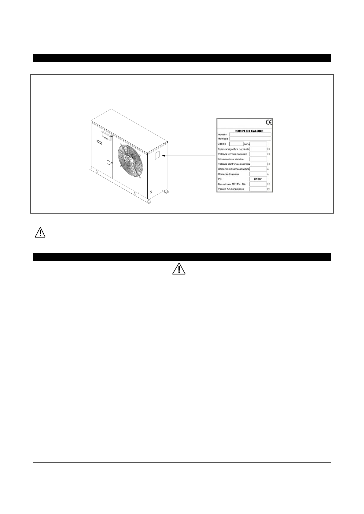
IDENTIFICATION
The unit can be identified through:
- - Rating plate
It bears the technical and performance data of the equipment.
Should this plate be damaged or mislaid, ask your local Technical Support Service for a duplicate.
Tampering with the rating plate, removing it or whatever else does not allow a sure identification of the product hinder
any installation or maintenance interventions.
GENERAL DIRECTIONS
After unpacking the appliance, check it for integrity and completeness. Should the content not match your order, please contact the retailer
who sold the equipment.
The equipment must be installed by a qualified company which, at the end of the work, must provide the proprietor with a declaration of
conformity stating that the installation complies with the best practice and the applicable national and local regulations, as well as the
indications of this instruction manual.
These appliances were made for room air heating and/or conditioning and must be destined for this use consistently with their performance
characteristics.
The manufacturer does not assume any contractual or extra-contractual liability for damages caused to people, animals or things by
installation, adjustment and maintenance errors or improper use.
In case of water leakage, turn OFF the main system circuit breaker and close the water taps.
Immediately call the Technical Support Service or professionally qualified personnel and do not personally intervene on the equipment.
The appliance contains refrigerant gas R 410A; act carefully in order not to damage the gas circuit and the finned coil. In case of refrigerant
leakage, turn OFF the main system circuit breaker. Immediately call the Technical Support Service or professionally qualified personnel and
do not personally intervene on the equipment.
The appliances must be exclusively equipped with original accessories. The manufacturer is not responsible for any damages resulting from
the improper use of the appliance and the use of non-original accessories and materials.
The references to laws, regulations, directives and technical standards mentioned in this manual have a mere informational purpose and are
valid at the printing date of the same. The manufacturer cannot be bound towards third parties on account of new regulations or
amendments to those already in force.
The installations to be made (gas piping, electric power supply, etc.) must be adequately fixed and avoid the risk of stumbling.
The manufacturer is responsible for the conformity of his product to the laws, directives and standards which were in force at the time of
marketing.
The knowledge and observance of regulations and standards about the system designing, installation, operation and maintenance are at the
exclusive charge of the designer, installer and user according to their spheres of competence.
4
The manufacture is not held responsible for the non-observance of the instructions contained in this manual, for the consequences of an y
unexpected operation or for any translations from which wrong interpretations may arise.
This appliance must be installed in accordance with the applicable national and local regulations and must be only used in a sufficiently
ventilated environment. Carefully read the instructions before installing and operating this equipment.
Should the unit be connected in parallel to a boiler, close the chiller cocks during the boiler operation.
The temperature of the circulating water inside the chiller should never exceed 60°C.
If you are not going to use the equipment for a long time, please do the following:
– Turn OFF the main system circuit breaker
– Close the water taps
– If there is danger of freezing, make sure an antifreeze liquid has been added to the system, otherwise empty the system
This instruction manual is an integral part of the appliance, therefore it must be kept with care and ALWAYS accompany the appliance if it is
transferred to another proprietor or user or moved to another system.. Should this manual be damaged or mislaid, ask your local Technical
Support Service for a new copy.
The repair or maintenance work must be carried out by the Technical Support Service or qualified personnel according to the prescriptions of
this manual. Do not alter or tamper with the appliance as this may lead to dangerous situations, and the manufacturer of the ap pliance will
not be held responsible for any damages caused.
.
Under adverse visibility conditions, use lighting devices enabling a perfect vision of all parts and components.
The refrigerant fluid contained in the refrigerating circuit is R-410A and it is not classified as dangerous in accordance with directive
1999/45/EC and relevant amendments.
Avoid high steam concentrations which may cause headache, vertigo, somnolence, nausea and other troubles.
In case of skin contact with the liquid, there is a residual risk of freezing through fast evaporation. Seek medical advice.
In case of inhalation, breath fresh air. Administer oxygen if breathing is difficult. Seek medical advice.
In case of eye contact, immediately flush with running water for at least 15 minutes. Seek medical advice.
The refrigerant fluid must be disposed of through authorized waste-disposal companies. In any case, the fluid must be recovered in proper
storage tanks.
FUNDAMENTAL SAFETY RULES
We remind you that the use of products using electric power, gas or gas oil entails the observance of some fundamental safety
rules, like the following:
The use of the appliance by children and unattended disabled people is prohibited.
Do not touch the appliance while barefoot and with wet or humid body parts
Do not perform any cleaning or maintenance before disconnecting the appliance from the mains (by turning OFF the main system circuit
breaker).
The safety and setting devices should not be altered without the appliance manufacturer’s consent and indications
Do not pull, tear or twist the electrical cables on the appliance, although this is disconnected from the mains.
Do not insert sharp objects through the air intake and supply grilles.
Do not open the equipment’s internal part access doors without first turning off the main system circuit breaker.
Do not abandon or leave to the children’s reach the packing material (cardboard, iron bands, plastic bags, etc.) as this is a potential source
of danger.
Do not install the appliance in environments with an aggressive atmosphere
Do not place any objects onto the equipment, nor slide them through the grille.
Do not use any adapters, multiple-outlet sockets or extensions for the electrical connection of the appliance.
Do not distribute this product in different countries, since it must be modified as to technical documentation and layout.
Do not perform any maintenance before disconnecting the appliance from the mains (by turning OFF the main all-pole system circuit
breaker).
.
.
.
5
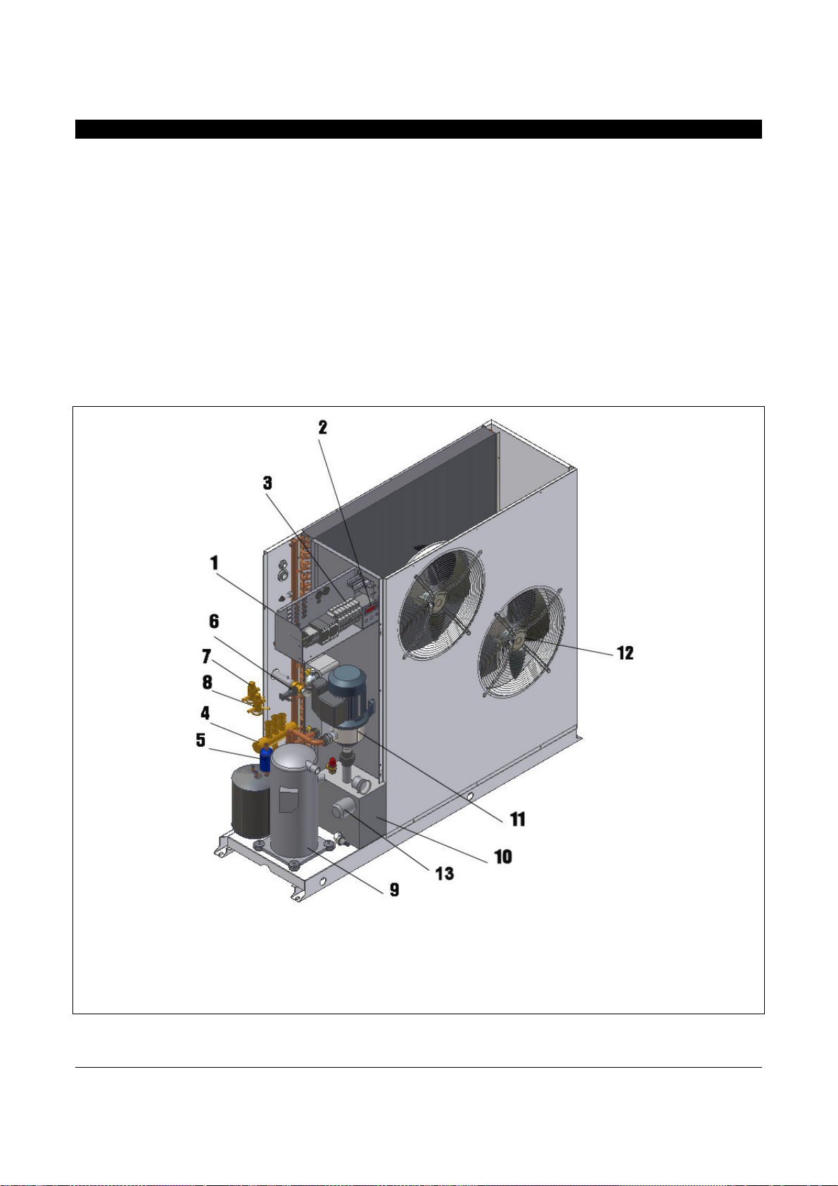
EQUIPMENT DESCRIPTION
The units are divided into two families:
– HEAT PUMPS, BESST series: some available with single-
phase power supply, others with three-phase power
supply, capable of producing both hot water for heating
and cold water for cooling household, residential and
industrial environments.
– HEAT PUMPS, BESST/R series: also av ailable with three-
and single-phase power supply, capable of producing both
hot water for heating and cold water for cooling household,
residential and industrial environments and provided with
supplementary electrical resistor for correct operation
even under very critical weather conditions.
They are used in combination with terminal or fan-coil units in small
and medium-large systems.
They are designed for outdoor installation and the used materials
have been selected to meet this special requirement.
They use a scroll-type rotating compressor, mounted on
antivibration supports inside an adequate compartment, and
electronically-controlled variable-speed helical fans, which
ensure particularly noiseless operation. For three-phase
versions, a phase monitor is standard supplied to check the
proper compressor rotation.
The AISI 318 stainless steel plate heat exchanger, on utility end,
is insulated with an anti-condensation coating and complete with
a flow controller.
The units are equipped with various safety devices, such as
pressure-switches, hydrometer, sensors, specific automatic
switches and phase monitor (only for three-phase units). An
electronic, microprocessor-controlled equipment supervises the
operation. They are also provided with an inertial storage tank
which is integrated into the unit as a standard.
1 Electric board
2 Control panel
3 Magnetothermal switch
4 Cycle reversing valve
5 Dehydration filter
6 Flow controller
7 Summer thermostatic valve
6
8 Winter thermostatic valve
9 Scroll compressor
19 Hydraulic kit
11 Pump
12 Helical fan
13 Electrical resistor (only BESST/R)

TECHNICAL DATA - WEIGHTS
BESST - BESST/R SERIES
Ref. UNI-EN 14511:2004 standard
TIPO
Heating capacity
Power input
Heating capacity
Power input
Heating capacity
Power input
Heating capacity
Power input
Heating capacity
Power input
(1)
(1)
(2)
(2)
(3)
(3)
(4)
(4)
(5)
(5)
kW
kW
kW
kW
kW
kW
kW
kW
kW
kW
1/9 2/10 3/11 4/12 5/13 6/14 7/15 8/16
6,8 8,3 11,0 15,0 19,9 22,2 28,0 37,2
1,74 2,11 2,81 3,61 4,28 4,83 6,48 8,44
5,9 7,2 9,5 13,0 16,6 18,9 23,8 31,7
1,78 2,20 2,90 3,67 4,33 4,86 6,55 8,52
5,0 6,2 8,0 10,8 13,5 15,4 19,2 25,8
1,79 2,26 2,97 3,73 4,36 4,88 6,66 8,63
6,6 8,1 10,6 14,4 18,4 21,0 26,4 34,8
2,14 2,68 3,50 4,49 5,23 5,96 7,84 10,18
5,6 7,1 9,3 12,6 15,9 18,1 22,6 30,0
2,16 2,77 3,60 4,60 5,26 5,99 8,00 10,33
Cooling capacity
Power input
Cooling capacity
Power input
Cooling capacity
Power input
Cooling capacity
Power input
(6)
(7)
(8)
(9)
(6)
(7)
(8)
(9)
kW
kW
kW
kW
kW
kW
kW
kW
7,5 10,3 13,0 17,8 23,6 27,2 33,9 45,1
1,80 2,28 2,93 3,89 4,96 5,67 7,04 9,05
6,9 9,3 11,8 17,0 21,3 24,6 31,0 40,4
2,00 2,72 3,46 4,56 5,78 6,60 8,13 10,51
6,0 8,2 10,2 14,1 17,9 21,0 26,9 34,9
1.76 2,34 3,01 3,93 5,03 5,69 7,05 9,19
5,3 7,1 9,3 13,0 17,0 19,5 24,7 32,2
2,04 2,81 3,58 4,65 5,85 6,66 8,22 10,71
Nominal water flow-rate
(10)
Water fitting diameter inches
Tank capacity - liters
Supporting resistor *
Supply voltage
Protection degree
Helical fan
Nominal air flow-rate
Sound level
(11)
R410A refrigerant charge
Loadless weight
(1) outdoor air +7°C, water 35 – 30°C.
(2) outdoor air +0°C, water 35 – 30°C.
(3) outdoor air -7°C, water 35 – 30°C.
(4) outdoor air +7°C, water 45 – 40°C.
(5) outdoor air +0°C, water 45 – 40°C.
(6) outdoor air +30°C, water 18 – 23°C.
(7) outdoor air +35°C, water 18 – 23°C.
(8) outdoor air +30°C, water 7 – 12°C.
(9) outdoor air +35°C, water 7 – 12°C.
(10) ref. outdoor air 0°C, water 35-30°C
(11) Sound level measure d under free-field conditio ns at 1.5 meters from fan front and 1.5 meters from the ground .
(*)only BESST/R version
m3/h
inches
litres
kW
V/50Hz
IP
N°
m3/h
dB(A)
kg
kg
1,0 1,2 1,6 2,2 2,8 3,2 4,1 5,4
3/4 3/4 1 1 1 1 1-1/4 1-1/4
16 16 36 36 57 57 70 70
3,0 3,0 6,0 6,0 8,0 8,0 10,0 10,0
230 ∼ 230
∼
230
∼
400 3N ∼ 400 3N ∼ 400 3N ∼ 400 3N ∼ 400 3N ∼
44 44 44 44 44 44 44 44
1 1 2 2 2 2 4 4
3.300 3.250 6.500 6.500 8.000 8.000 14.000 13.600
58,0 58,0 62,8 62,8 61,5 61,5 63,0 63,0
1,7 1,9 2,7 3,1 4,9 5,5 8,2 9,6
110 112 164 175 224 230 390 394
7

HYDRAULIC DATA
The following diagram shows the residual lifts with nominal water flow-rate ± 20%.
WATER FLOW RATE – LIFT DIAGRAM
Type 7-15
Type 5-13
Type 8-16
Type 1-9
AVAILABLE LIFT kPa
Do not work outside these curves
Type 3-11
Type 2-10
Type 6-14
Type 4-12
WATER FLOW RATE m3/h
8
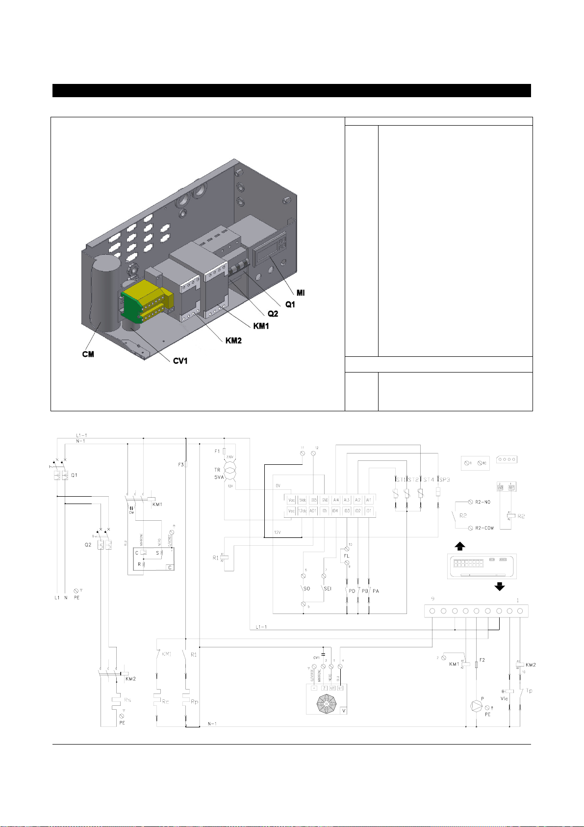
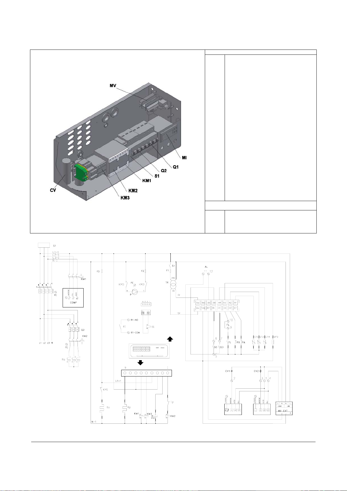
ELECTRIC BOARD AND MULTIFILAR WIRING DIAGRAM
The units are provided with an electric board consisting of the following components.
Type 1, 2, 9, 10
Factory-installed c om ponents
C
CM
CV1
F1
F2
F3
KM1
KM2
MI
Conn.A
Conn.B
P
PD
Tp
TR
Q1
Q2
SP3
ST1
ST2
ST4
PA
PB
VIC
Rp
Rc
Rs
R1 / R2
V1
(*)
Components to be assembled upon installation
(not supplied with the appliance)
AL
FL
SEI
SO
Compressor
Run capacitor
Fan capacitor
Control protection fuse
Pump protection fuse
Resistor protection fuse
Compressor remote switch
Resistor remote switch
Control panel
Input terminal block
Load output terminal block
Circulating pump
Flow controller
Protection thermostat
Auxiliary circuit transformer
Automatic main breaker
Supporting resistor automatic switch
Pressure transducer
Exchanger inlet temperature probe
Exchanger outlet temperature probe
Outdoor air temperature probe
High pressure switch
Low pressure switch
Cycle reversing valve
Plate heat exchanger resistor
Compressor crankcase resistor
Supporting resistor
RP relay / Boiler contact auxiliary relay
Fan
(*) only for BESST/R version
Remote alarm signaling system (12V DC output,
max 20 mA)
External flow switch
Remote SUMMER-WINTER switch
Remote ON-OFF switch
230V 50Hz
AL-12V DC
CONN C
CONN C
CONN A
CONN A
CONN C
CONN B
CONN B
9
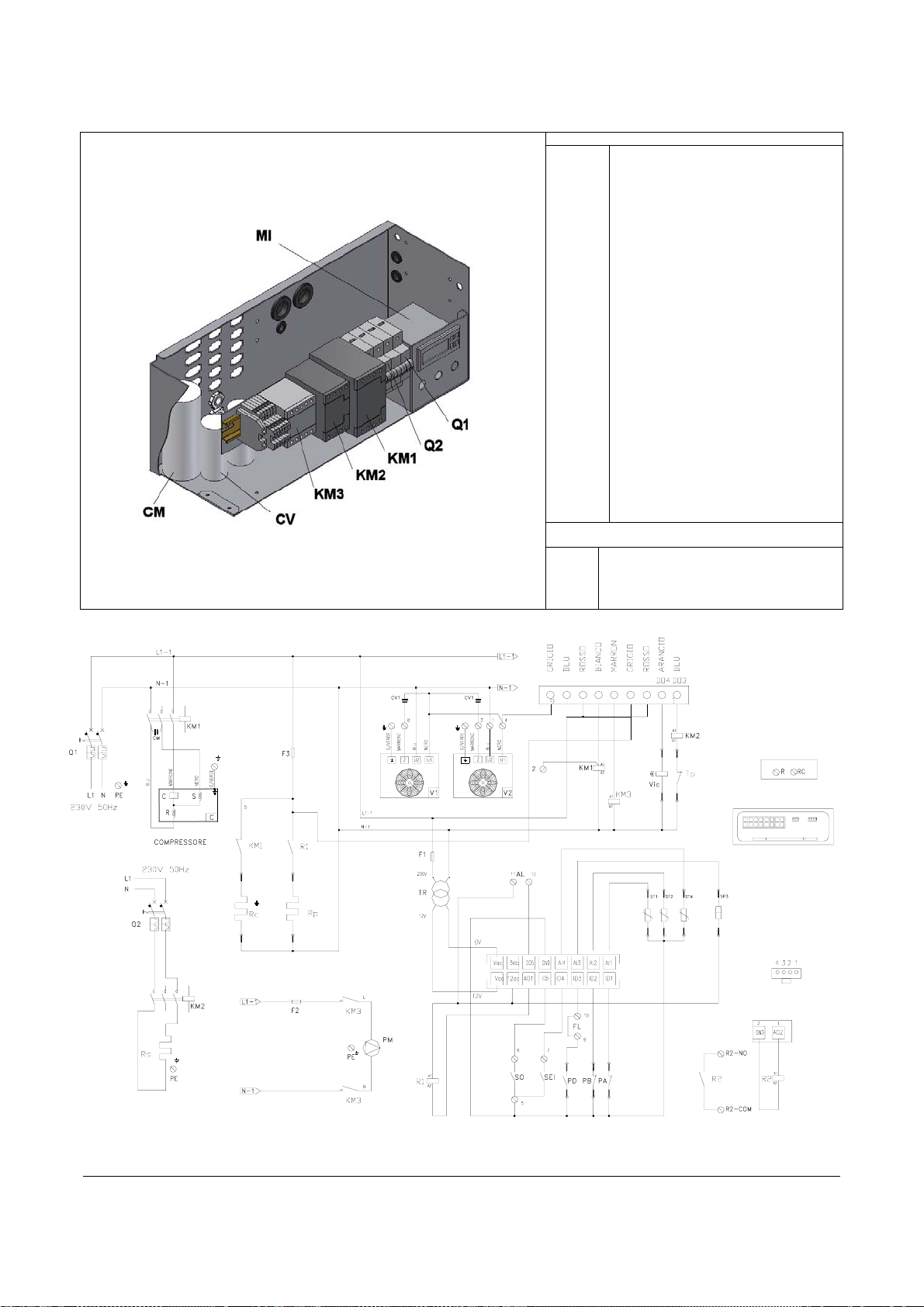
Type 3 and 11
Factory-installed c om ponents
C
CM
CV1/2
F1
F2
F3
KM1
KM2
KM3
MI
Conn.A
Conn.B
P
PD
Tp
TR
Q1
Q2
SP3
ST1
ST2
ST4
PA
PB
VIC
Rp
Rc
Rs
R1 / R2
V1/2
(*)
Components to be assembled upon installation
(not supplied with the appliance)
AL
FL
SEI
SO
Compressor
Run capacitor
Fan 1/2 capacitor
Control protection fuse
Pump protection fuse
Resistor protection fuse
Compressor remote switch
Resistor remote switch
Pump remote switch
Control panel
Input terminal block
Load output terminal block
Pump/ Circulating pump
Flow controll er
Protection thermostat
Auxiliary circuit transformer
Automatic main breaker
Supporting resistor automatic switch
Pressure transducer
Exchanger inlet temperature probe
Exchanger outlet temperature probe
Outdoor air temperature probe
High pressure switch
Low pressure switch
Cycle reversing valve
Plate heat exchanger electrical resistor
Compressor crankcase resistor
Supporting resistor
RP relay / Boiler contact auxiliary relay
Fan 1/2
Only for BESST/R series
Remote alarm signaling system ((12V DC output,
max 20 mA)
External flow switch
Remote SUMMER-WINTER switch
Remote ON-OFF switch
CONN B
CONN A
CONN C
CONN B
CONN A
CONN C
CONN C
10
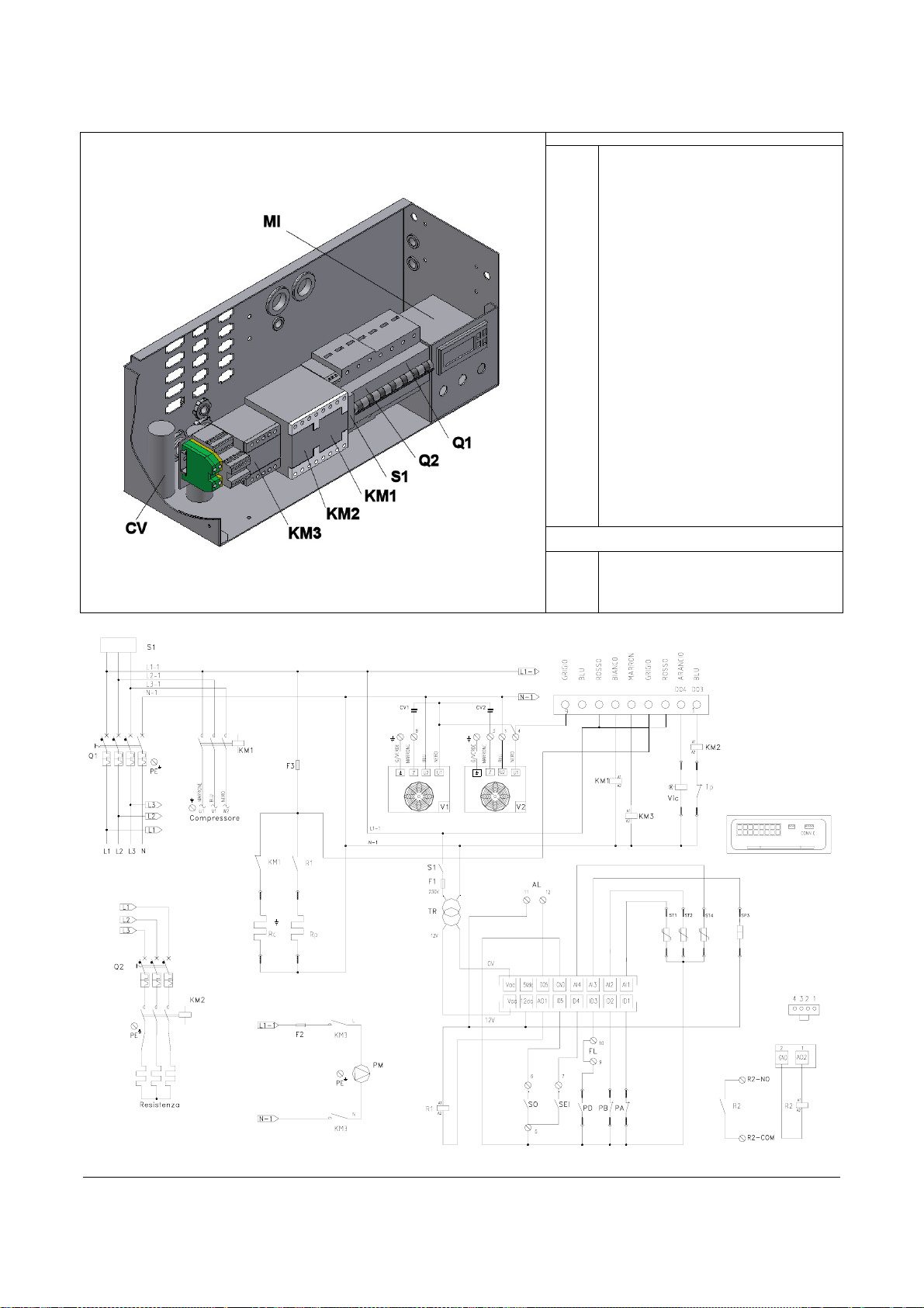
Type 4 and 12
Factory-installed c om ponents
C
CV1/2
F1
F2
F3
KM1
KM2
KM3
MI
Conn.A
Conn.B
P
PD
Tp
TR
Q1
Q2
S1
SP3
ST1
ST2
ST4
PA
PB
VIC
Rp
Rc
Rs
R1 / R2
V1/2
(*)
Components to be assembled upon installation
(not supplied with the appliance))
AL
FL
SEI
SO
Compressor
Fan 1/2 capacitor
Control protection fuse
Pump protection fuse
Resistor protection fuse
Compressor remote switch
Resistor remote switch
Pump remote switch
Control panel
Input terminal block
Load output terminal block
Pump/Circulating pump
Flow controller
Protection thermostat
Auxiliary circuit transformer
Automatic main breaker
Supporting resistor automatic switch
Phase sequence relay
Pressure transducer
Exchanger inlet temperature probe
Exchanger outlet temperature probe
High pressure switch
Low pressure switch
Cycle reversing valve
Plate heat exchanger electrical resistor
Compressor crankcase resistor
Supporting resistor
RP relay / Boiler contact auxiliary relay
Condensation fans 1/2
Only for BESST/R series
Remote alarm signaling system (12V DC output,
max 20 mA)
Secondary flow switch
Remote SUMMER-WINTER switch
Remote ON-OFF switch
400V 50HZ 3N
Rs
CONN B
CONN A
CONN B
CONN A
CONN C
CONN C
11
Type 5, 6, and 13, 14
Factory-installed c om ponents
C
CV1/2
F1
F2
F3
KM1
KM2
KM3
MI
MV
Conn.A
Conn.B
P
PD
Tp
TR
Q1
Q2
S1
SP3
ST1
ST2
ST4
PA
PB
VIC
Rp
Rc
Rs
R1
V1/2
(*)
Components to be assembled upon installation
(not supplied with the appliance)
AL
FL
SEI
SO
Compressor
Fan 1/2 capacitor
Control protection fuse
Pump protection fuse
Resistor protection fuse
Compressor remote switch
Resistor remote switch
Pump remote switch
Control panel
Fan modulation board
Input terminal block
Load output terminal block
Pump
Flow controller
Protection thermostat
Auxiliary circuit transformer
Automatic main breaker
Supporting resistor automatic switch
Phase sequence relay
Pressure transducer
Exchanger inlet temperature probe
Exchanger outlet temperature probe
Outdoor air temperature probe
High pressure switch
Low pressure switch
Cycle reversing valve
Plate heat exchanger electrical resistor
Compressor crankcase resistor
Supporting resistor
Boiler contact au xiliary relay
Condensation fans 1/2
Only for BESST/R series
Remote alarm signaling system (12V DC output,
max 20 mA)
Secondary flow switch
Remote SUMMER-WINTER switch
Remote ON-OFF switch
400V 3N - 50HZ
12
CONN B
CONN C
CONN C
CONN A
CONN A
CONN C

Type 7, 8 and 15, 16
Factory-installed c om ponents
C
CV1/2/3/4
F1
F2
F3
KM1
KM2
KM3
MI
MV
Conn.A
Conn.B
P
PD
Tp
TR
Q1
Q2
S1
SP3
ST1
ST2
ST4
PA
PB
VIC
Rp
Rc
Rs
R1
V1/2/3/4
(*)
Components to be assembled upon installation
(not supplied with the appliance)
AL
FL
SEI
SO
Compressor
Fan 1/2/3/4 capacitor
Control protection fuse
Pump protection fuse
Resistor protection fuse
Compressor remote switch
Resistor remote switch
Pump remote switch
Control panel
Fan modulation board
Input terminal block
Load output terminal block
Pump
Flow controller
Protection thermostat
Auxiliary circuit transformer
Automatic main breaker
Supporting resistor automatic switch
Phase sequence relay
Pressure transducer
Exchanger inlet temperature probe
Exchanger outlet temperature probe
Outdoor air temperature probe
High pressure switch
Low pressure switch
Cycle reversing valve
Plate heat exchanger electrical resistor
Compressor crankcase resistor
Supporting resistor
Boiler contact auxiliary relay
Condensation fans 1/2/3/4
Only for BESST/R series
Remote alarm signaling system (12V DC output,
max 20 mA)
Secondary flow switch
Remote SUMMER-WINTER switch
Remote ON-OFF switch
400V 3N - 50HZ
CONN A
CONN A
CONN C
CONN B
CONN B
CONN C
CONN C
13

HEAT PUMP
In Winter cycle
COOLING CIRCUIT
1
8
In Summer cycle
8
9
12
16
10
15
1114
2
54
7
33
136
1
12
7
16
10
15
5 4
136
9
1114
2
3 3
COMPONENTS:
1
Fan
2
Finned coil (condenser)
3
Check valve
4
Thermostatic valve (Summer cycle)
5
Thermostatic valve (Winter cycle)
6
Filter
7
Liquid indicator
8
Flow controller
14
9
10
11
12
13
14
15
16
Plate heat exchanger
Cycle reversing valve
High pressure safety switch
Compressor
Liquid receiver
Low pressure safety switch
Pressure transducer
Safety valve

ACCESSORIES
Below is a list of available accessories to be separately ordered.
ACCESSORY CODE
Remote control kit 4TRRT02
Antivibration mount kit 4TRAV01
Soft start kit 4TRRS01
Enclosure kit 4TRKP01 - 4TRKP02 - 4TRKP03 - 4TRKP04
SUPPORTING RESISTOR.
The control panel enables all necessary settings for the heat pump operation and displaying of main
parameters and alarms.
It is located on the electric board front, inside the equipment, and can be accessed through a small door on the inspection panel.
CONTROL PANEL
The control panel enables all necessary settings for the heat pump operation and displaying of main
parameters and alarms.
It is located on the electric board front, inside the equipment, and can be accessed through a small door on the inspection panel.
Alarm icon Mode (Heat; Cool…) icons
Economy icon
(configurable)
Clock icon
Resource (compressor, fans…) icon Menu navigation icon
Display:
During normal operation, it shows the return water temperature from the system.
It can also show the values of all set parameters and the codes of any alarms.
Displayed quantity measure
unit
15

Keys Press and immediately release
Symbol printed on
front frame
Press and hold (if key is
properly configured)
Scroll menu items, increase parameter
values
Scroll menu items, decreases
parameter values
Manual alarm reset
Acces to machine status menu (set
point, AI,DI,DO, compl.hours,pump
hours,etc.)access to menu subfolders,
access to parameter value, confirmation
of parameter value
Exit from menu, parameter list,
parameter value and return to upper
Access to programming menu
Request for manual
defrosting
Device switch on/off (and
vice-versa)
Access to essential
display configuration
folder
Access to operation mode
(Heat/Cool/Std-by)
SET used for:
• access to machine status menu
• access to menu subfolders
• access to parameter value
• confirmation of parameter value and/or exit
• pressing and holding the key gives access to the essential display selection menu (if the key is
• configured for this function); the available options can be displayed with the up and down keys (depending on the machine configuration)
UP
• scrolling up the displayed folders and parameters
• increase of parameter value (if in parameter value change mode)
• pressing and holding the key gives access to the manual defrosting feature (if the key is configured for this feature), from essential display
only.
DOWN
• scrolling down the displayed folders and parameters
• decrease of parameter value (if in parameter value change mode).
• Pressing and holding the key switches on/off the essential display device (if the key is configured for this feature)
ESC
Exit from menu, parameter list, parameter value without saving it, and return to previous level. Pressing and holding the key from the
essential display (if the key is configured for this feature) gives access to the operating mode change folder; the available modes can be
displayed with the UP and DOWN keys (depending on the machine configuration), while pressing the SET button confirms the selection
made.
and pressing the SET key confirms the selection made.
used for:
used for:
used for:
Simultaneously pressing SET
Simultaneously pressing UP
16
+ESC gives access to the Parameters, Functions, Password folders, etc.
+DOWN resets any alarms

FAULT INDICATIONS
In case of abnormal operation of the equipment, alphanumerical
codes alternating with the system
return temperature are displayed on the control panel display.
Some alarms are automatically reset, whereas others can only be
reset by the manufacturer’s Technical Support
MANUAL FAULT RESET
To reset a fault alarm after removing the cause which triggered it:
Service.
DESCRIPTION INDICATION RESET
High pressure
Low pressure
Flow controller
Water circuit antifreeze
High water temperature (over 60° C)
Faulty-clock error
Not-set clock error
Inlet temperature probe
Outlet temperature probe Er61 automatic
Outside temperature probe fault
Condensation pressure probe
Configuration error
Compressor work hours exceeded
Pump work hours exceeded
Alarm history records exceeded
Er01
Er05
Er20
Er30
Er35
Er45
Er46
Er60
Er68
Er75
Er80
Er81
Er85
Er90
manual
manual
manual
automatic
automatic
automatic
automatic
automatic
automatic
manual
manual
manual
Simultaneously press UP
alarms
and DOWN to reset the
SWITCHING ON AND OFF
After the first commissioning by the manufacturer’s Technical Support Service, the unit is set for “automatic” operation and no further
interventions are required.
Therefore, the system manager must SWITCH ON or OFF the unit from the control panel or the
remote switch (if present).
To access the control panel, open the relevant door and do the
following
- Remove the lock screw
- Simultaneously press the (A) points and lift the door
After operating the control panel:
- Close the door and replace the lock screw.
:
After powering on the unit, the OFF indication is displayed. Press the key to bring the machine to stand-by mode, from this
moment the pump should activate and the system return water temperature appear on the display. At this point, act as follows:
Switching on
To select the operating mode, press and hold the key
“HEAT”,“COOL” or “STBY” ” is displayed, depending on the
controller’s current operation status.
Select with UP
confirm with the SET
or DOWN the HEAT mode and
key.
until
17

Heating (WINTER CYCLE))
Selecting HEAT the
Cooling (SUMMER CYCLE)
Selecting COOL the
symbol lights up
symbol lights up.
Switching off the heating/cooling modes
Hold for some seconds
; the symbol lights up.
The switching between Heating and Cooling modes, on
heat pump models, should be made by the
manufacturer’s Technical Support Service.
until COOL” or HEAT (cycle on) is displayed. Select with the key STBY and confirm with SET
OPERATIONS MADE BY THE ON-OFF AND “SEI” SUMMERWINTER REMOTE SWITCHES (IF PRESENT)
Switching on the cooling mode
- Turn OFF the “SEI” SUMMER-WINTER remote switch
- Turn ON the “SO” ON-OFF remote switch
The indicator LED
lights up on the control panel.
It is recommended to switch the operating mode only once
a day.
Switching off the cooling mode
- Turn OFF the “SO” ON-OFF remote switch.
The OFF indication starts flashing on the CONTROL
PANEL.
Switching on the heating mode
- Turn ON the “SEI” SUMMER-WINTER remote switch
- Turn ON the “SO” ON-OFF remote switch”.
The indicator LED
Switching off the heating mode
Turn OFF the “SO” ON-OFF remote switch
The OFF indication starts flashing on the CONTROL
PANEL.
In case of power failure for more than four hours, after
restoring the unit, keep it powered but switched off for at
least eight hours..
lights up on the control panel..
18

In case of power failure for less than four hours, after
restoring the unit, keep it powered but switched off for the
same number of hours the power failed
INACTIVITY FOR A LONG PERIOD INACTIVITY FOR A LONG PERIOD
If you are not going to use the equipment for a long time, please
do the following:
– Switch off the equipment, whatever its operating mode, using
the control panel
– Turn OFF the remote switch (if present)
After switching off the equipment:
– Switch off the internal terminal units by turning off the switch
of each appliance
– Turn OFF the main system circuit breaker
– Close the water taps
If the outside temperature can drop below zero, there is a
danger of freezing.
The hydraulic system MUST BE DRAINED or an
antifreeze liquid (such as ethylene glycol) must be added
to it according to the doses recommended by the liquid’s
manufacturer. Please, contact the manufacturer’s
Technical Support Service on the matter.
CL CLE CLEANING
The only cleaning operation which the user must perform
concerns the chiller external panels which must be only cleaned
using a cloth dampened with water and soap. In the event of
resisting stains, dampen the cloth with a 50% mix of water and
denaturated alcohol or with specific products. After the cleaning,
carefully dry the surfaces.
MAINTENANCE
Periodical maintenance is essential to keep the equipment effective,
safe and reliable over time.
It can be done, every six months for some interventions and
every year for others, by the manufacturer’s Technical Support
Service which is technically skilled and trained and provided
with genuine spare parts, if necessary..
USEFUL INFORMATION
Seller:…………………………………………………………..
Street …………………………………………………………………...
Phone.
…………………………………………………………………..
Installer: ………………………………………………………...
Mr. …………………………………………………………………..
Street ……………………………………………………………………
Phone.
……………………………………………………………………
DATE INTERVENTION
It is recommended to switch the operating mode only once a
day.
To put the equipment back into operation after a long
downtime, ask for the intervention of the manufacturer’s
Technical Support Service .
Should the unit be connected in parallel to a boiler, close
the equipment cocks during the boiler operation. The
temperature of the circulating water inside the heat pump
should never exceed 60°C.
Do not use sponges impregnated with abrasive products or
powder detergents
Do not perform any cleaning or maintenance before
disconnecting the appliance from the mains (by turning OFF
the main system circuit breaker)
For equipment installed near the sea, maintenance intervals
must be cut by half.
Do not perform any maintenance before disconnecting the
appliance from the mains (by turning OFF the main all-pole
system circuit breaker).
Technical Support Service: ……………………………………….
Mr.…………………………………………………………………………..
Street…………………………………………………………………………...
Phone.……………………………………………………………………………
19

UPON RECEIVING THE PRODUCT
Check if the received product is intact and whether the packing
list matches the labels on the package. Should the content not
match your order, please contact the retailer who sold the
equipment and the carrier. The units are supplied in a single
package on a wooden pallet, protected by a cardboard
wrapping, and they are accompanied by::
– instruction manual
– warranty certificate
– labels with barcodes
The instruction manual is an integral part of the equipment,
therefore we recommend you to read it and keep it with care.
.
It is recommended to remove the wrapping only when the
equipment has been positioned in the installation site.
Do not abandon the packing material or leave it to the
children’s reach, as this is a potential source of danger
HANDLING AND TRANSPORT
Handling and transport must be always carried out with the
equipment in horizontal position. If a lift truck is used, fork the
appliance on the bottom, opening wide the truck forks to the
maximum extent. If a crane is used, slide the ropes into the
upper part of the wooden base, taking care not to put pressure
on the equipment.
It is recommended to remove the wrapping only when the
equipment has been positioned in the installation site..
Dimension / Type 1, 2, 9, 10 3, 4, 11, 12 5, 6, 13, 14 7, 8, 15, 16
L 1140 1340 1600 1990 mm
H 950 1150 1450 1650 mm
D 480 540 580 670 mm
Once the wrapping has been removed, the units can be
handled by inserting two metal tubes (max. diameter: 33 mm,
min. thickness: 3.2 mm) into the holes provided in the base and
using adequate lifting devices.
The equipment weight is unbalanced toward the
compressor end (electric board end).
During the transport, the unit must be maintained in
vertical position only.
The appliance must be handled by qualified personnel,
adequately equipped with devices sized for the appliance
weight and dimensions
20

LOCATION
The installation site must be determined by the system designer or a
competent person and must take into account technical requirements
and applicable laws and regulations which prescribe special
authorizations, (ex.: city planning, architectural, environmental
regulations, etc.).
It is therefore recommended to request and obtain the necessary
authorizations before installing the equipment.
The equipment must:
– be placed on an even surface which can support its weight.
– be placed on a sufficiently stiff floor slab which does not
transmit any vibration to the premises located under or adjacent
to it.
It is recommended to insert a rubber layer (hardness: 60 shores,
thickness: 10 mm) between floor slab and equipment, or use the antivibration mounts available as an accessory.
POSITION FOR ANTI-VIBRATION MOUNT FIXATION
B
A
Size 1-2-9-10 3-4-11-12 5-6-13-14 7-8-15-16
A 1000 1200 1500 1500 mm
B 500 600 700 700 mm
C 1000 1000 1000 1000 mm
D 600 800 800 800 mm
The area in front of the condensation fans must be totally
free from obstacles
If multiple appliances are installed side by side on the
external coil end, clearances must be summed up .
The unit is destined for outdoor installation and must be located
within a buffer area in accordance with the figure below. The defined
clearances are required to enable a correct air flow and allow for
normal cleaning and maintenance operations.
It is advisable to avoid:
– the installation in skylight shafts and/or basement window wells
– obstacles or barriers causing the recycling of exhaust air
– the installation in sites with an aggressive atmosphere
– the installation in sites where the equipment noise may be
enhanced by reverberation or echoes
the installation in corners with settling of dust, leaves and whatever
-
may reduce the appliance efficiency, obstructing the air path
– the penetration of the equipment exhaust air into lived-in rooms
through doors or windows, causing trouble to people.
TYPE 1-2-9-10
TYPE 3-4-11-12
TYPE 5-6-13-14
TYPE 7-8-15-16
A 1070 mm
B 325 mm
A 1270 mm
B 375 mm
A 1530 mm
B 425 mm
A 1920 mm
B 525 mm
The two appliances should not be installed one with the fan
air supply facing the finned coil of the other
21

HYDRAULIC CONNECTIONS
The choice and installation of the components is the installer’s
responsibility who must work according to the best practice rules and
the regulations in force. Before connecting the pipes, make sure they
do not contain stones, sand, rust, waste or anyway foreign bodies
which might damage the system.
System hydraulic connection diagram
1-2-9-10-type heat pump
A system “calibration” by-pass MUST be made for types 56-7-8 and 13-14-15-16 (see drawing below). The by-pass
enables a better control of water flow-rate and lift, since the
provided pump is pre-equipped for a single speed.
F
DELIVERY TO SYSTEM
RETURN FROM SYSTEM
1 Pressure gauge
2 Antivibration coupling
3 Check valve
4 Mesh filter
5 Flow controller
F
3-4-5-6-7-8 type and 11-12-13-14-15-16 type heat pump
F
RETURN FROM SYSTEM
DELIVERY TO SYSTEM
F
6 Pump
7 Safety valve
8 Air vent
9 Expansion tank
10 Temperature probe
11 Fill/top up
12 Drain cock
13 Calibration by-pass (compulsory on 5-6-7-8 types and 13-14-
15-16 types)
14 Flow switch
22

A
The hydraulic connections must be completed installing:
–
- a 0.5 mm inlet mesh filter (return from system).
- an outlet liquid flow switch (delivery to system) to be sized and set
depending on the system hydraulic characteristics: it must be
installed halfway of a straight horizontal pipe section of at least 1
meter of length
Together with the flow controller onboard the machine, the flow
switch must ensure a correct water flow rate across the
equipment (with a min. temperature of 4°C and a max.
temperature of 6°C);;
Special feeding/top-up waters must be conditioned with
proper treatment systems. The values listed in the table below
can be taken into account as reference values.
REFERENCE VALUES
PH 6÷8
Electrical conductivity lower than 200 mV/cm (25°C)
Chlorine ions lower than 50 ppm
Sulfuric acid ions lower than 50 ppm
Total iron lower than 0,3 ppm
M-alkalinity lower than 50 ppm
Total hardness lower than 50 ppm (5 °F)
Sulfur ions zolfo
mmonia ions
Silica ions lower Than 30 ppm
ppm = parts per million
none
none
– air vent valves in the piping upper points;
- flexible couplings;
- check valves;
- chemical washing check valves.
The calibration by-pass must be installed downstream of the
machine for better regulation of the water flow-rate and lift
within the system.
Provide a system fill/top-up device and a drain device to be
connected in the lower part of the hydraulic circuit.
Systems filled with antifreeze liquid or covered by
special law provisions must be fitted with hydraulic
disconnectors. The manufacturer is not liable for
obstruction, breakage or noise resulting from the
failure to install filters, flow switches or vibration
dampers.
The units are equipped with a pump as a standard.
In addition, the water flow-rate must be maintained
constant during operation.
The system water content must be adequate, in order o
avoid unbalances in the cooling circuit operation (see table
on page 7)
DIMENSIONS
H
L
L1
Dimensions / Type 1 - 2 - 9 - 10 3 – 4 – 11 - 12 5 – 6 – 13 - 14 7 – 8 – 15 - 16
P1
P
L 1040 1240 1500 1890 mm
H 805 1000 1305 1500 mm
P 378 428 478 570 mm
L1 1100 1300 1560 1950 mm
D1 425 472 520 615 mm
Return/Delivery 3 / 4 ” 1 ” 1 ” 1 ¼ “ inch
Top-up
1 / 2 ” 1 / 2 ” 1 / 2 ” 1 / 2 ” inch
For weights, refer to page 7.
23

SIZE AND LOCATION OF CONNECTIONS
Type 1-2 and 9-10
M: delivery to system
R: return from system
r: water top-up
R
r
M
65
330
Type 3-4 and 11-12
M
r
R
40 345
55
120
130 55
255
625
24

SIZE AND LOCATION OF CONNECTIONS
Type 5-6 and 13-14
M
r
R
40
Type 7-8 and 15-16
350
685
130 60
M: delivery to system
R: return from system
r: water top-up
ELECTRICAL CONNECTIONS
Units leave the factory completely wired and ready for
connection to the mains electricity supply and for the flow switch
connection, which must be carried out by qualified personnel in
accordance with current legislation.
For any intervention of electrical nature, please refer to the wiring
diagrams contained in this manual.
It is also recommended to check the following::
– - if the characteristics of the mains power supply are adequate
M
1285
135
r
R
95
425
For electrical connections use double insulation cables.
It is compulsory:
– to use a main magnetothermal, all-pole circuit breaker to
protect the mains line
– to establish an efficient earth connection.
The use of gas and water pipes for the appliance earth
25

for the power input values indicated in the electrical
characteristics table, also considering any other equipment in
parallel operation.
– if the supply voltage matches the rated value ± 10%, with a 3%
maximum unbalance between phases.
connection is prohibited.
Failure to earth the appliance or observe the wiring diagrams
relieves the manufacturer of all liability for damage.
POWER SUPPLY LINE SIZING TABLE FOR BESST VERSION ONLY:
:
TYPE Supply voltage
1 – 9
2 – 10
3 – 11
4 – 12
5 – 13
6 – 14
7 – 15
8 – 16
(V-ph~Hz)
230 ~ 50 2.72 14.6 58
230 ~ 50 3.75 19.0 82
230 ~ 50 4.66 27.8 97
400 - 3N ~ 50 5.95 16.2 64
400 - 3N ~ 50 7.15 17.5 74
400 - 3N ~ 50 8.25 19.0 101
400 - 3N ~ 50 10.00 22.0 111
400 - 3N ~ 50 12.80 27.2 118
Max power input
(kW)
Max current input
(A)
Starting current
(A)
CAUTION:WHEN SIZING THE POWER SUPPLY LINE FOR THE BESST/R VERSION, THE
ELECTRIC RESISTANCE VALUE MENTIONED ON PAGE 7 (TECHNICAL DATA) MUST
ALSO BE CONSIDERED ,TOGETHER WITH THE POWER VALUE SHOWN IN THE
TABLE ABOVE
CABLE GLAND FOR POWER LINE ENTRY AND EXTERNAL
CONNECTIONS
The equipment is provided with proper cable glands for main
power supply cables and other electrical connections.
- Insert the main power supply cable into the larger cable gland
- Slide the cables from the outside guiding them toward the
electric board.
Avoid direct contact with the non-insulated copper pipes
and the compressor.
The power supply cables should not enter the appliance
in positions which are not specifically shown in this
manual.
Cable gland for power line entry and external connections.
26

NOTE FOR FIRST STARTUP:
THE APPLIANCE MUST BE ALWAYS POWERED TO ENABLE CORRECT PRE-HEATING OF THE COMPRESOR OIL. THE
APPLIANCE MUST HAVE BEEN POWERED F OR AT LEAST EIGHT HOURS BEFORE THE FIRST STARTUP IS POSSIBLE.
The electric board with the connection terminal block is located inside the equipment, in the upper part of the circuit component
compartment.
Before starting any operations, turn OFF the
main system circuit breaker
To make the electrical connections:
– Undo the four fixation screws on the inspection panel
– Remove the panel
– Turn OFF the main equipment switch A
A
– Use hole A for the main power supply line and hole B for
the other external connection cables.
A
B
27
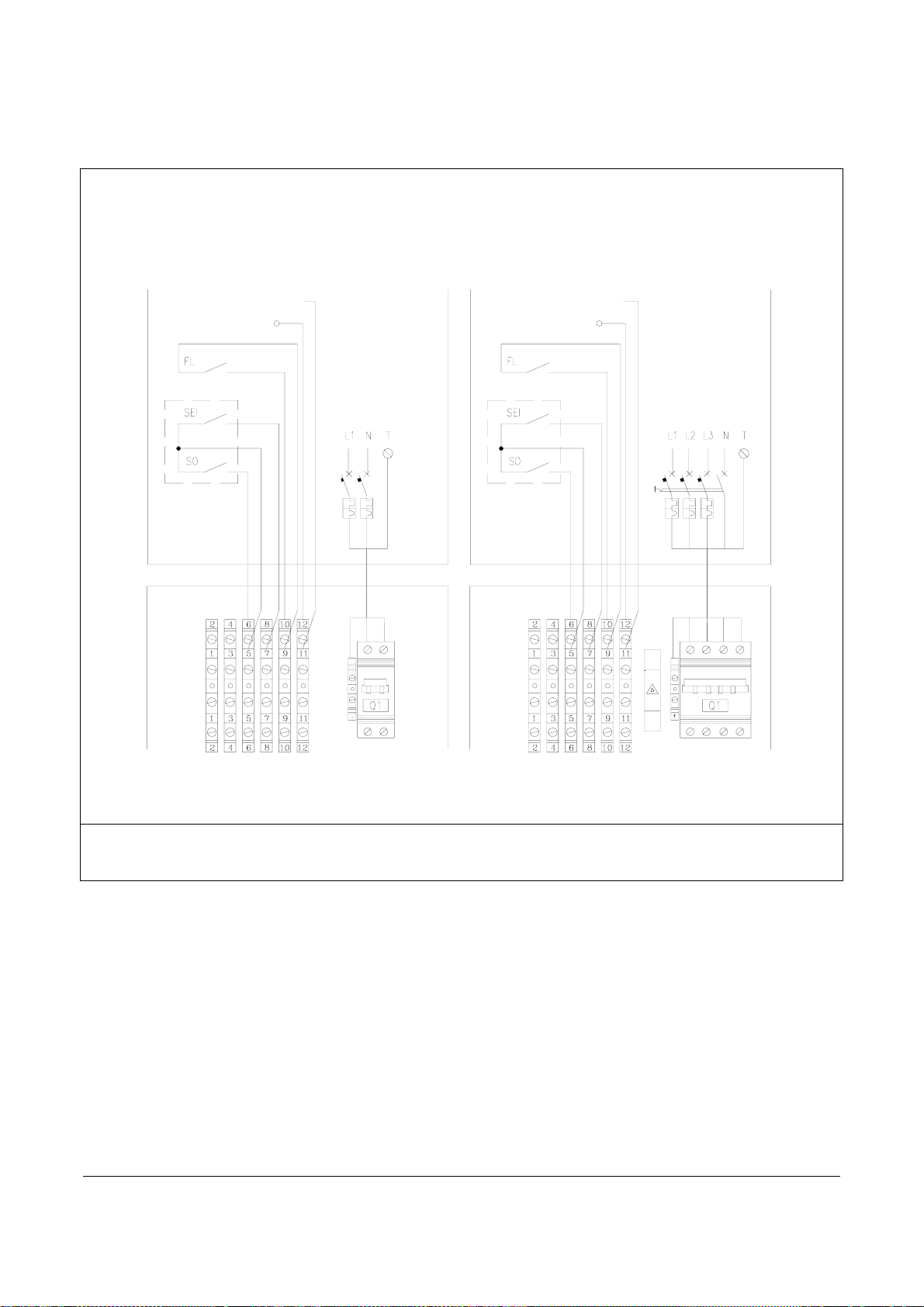
– Make the connections as shown in the figure.
V
ersione Monofase
Versione Monofase Versione Trifase
REMOTE ALARM SIGNAL
AL 12 V DC OUTPUT
COLLEGAMENTI ESTERNI
COLLEGAMENTI ESTERNI
(A CURA DELL'INSTALLATORE)
(A CURA DELL’INSTALLATORE)
REMOTE ALARM SIGNAL
POWER SUPPLY
230 V – 50 HZ
COLLEGAMENTI INTERNI
INTERNAL CONNECTION
ESEGUITI IN FABBRICA
MADE IN FACTORY
POWER SUPPLY
400V 3+N ∼ 50 HZ
S1
FL External flow switch
SEI Remote SUMMER-WINTER switch
SO Remote ON-OFF switch
AL Remote alarm signaling system (12V DC output, max 20 mA)
After making the electrical connections, lock the cables with the cable glands, turn ON the main equipment switch and replace the inspection
panel through the proper fixation screw.
28

ENABLING THE “SO” AND “SEI” CONTROLS”
DO THE FOLLOWING FROM THE CONTROL PANEL:
The operations described below must be carried out with the maximum care so as not to affect the equipment regular operation.
In case of errors or interpretation doubts, please WAIT 15 SECONDS WITHOUST PRESSING ANY KEYS.
To enable the SO and SEI controls, act as follows:
Power on the unit, by turning ON the main system circuit breaker and the main equipment switch”. If this is the first startup, the OFF
indication appears on the display. In this case, press the
temperature value appears on the display.
-
HOW TO SET THE“SO” (ON-OFF) REMOTE CONTROL):
- Now press the
indicating access to user parameters.
- Now press the
and keys simultaneously to access the user parameters. The “Par” indication appears on the display,
key to access the CF menu.
key to bring the machine back to stand-by. At this point, the return
.
- The CF indication appears on the display, indicating the remote control parameter menu.
Pressing the
set the remote SO control, just press
- Press the
- Power off the machine to store the value. - Power on again and check with the key
HOW TO SET THE“SEI” (SUMMER-WINTER CYCLE SWITCHING) REMOTE CONTROL
- Now press the
indicating access to user parameters.
key CF19 is displayed: with the arrow key move to CF20, which indicates the “SO” parameter, that is ON-OFF To
reduce the value from 0 to –13 (minus 13); then confirm with the key.
key, , until the return water temperature value appears on the display.
and keys simultaneously to access the user parameters. The Par indication appears on the display,
- Now press the key to access the CF menu.
- The CF indication appears on the display, indicating the remote control parameter menu.
- Pressing the SET
key CF19 is displayed, which indicates the “SEI” parameter, that is remote summer/winter switching. To enable
the remote control, just press
- Press the
key, until the return water temperature value appears on the display.
and reduce the value from 0 to -14 (minus 14) with the arrow keys; then confirm with the key .
FILLING AND EMPTYING THE SYSTEM
FILLING
– Before starting to fill the system, turn OFF the main system
circuit breaker.
- Check if all the equipment and system drain cocks are closed
- Open all the equipment, system and respective terminals vent
valves
29

– Open the system shut-off devices
– Start the filling by slowly opening the system water fill cock “A”
outside the appliance
– When water begins to come out of the vent valves, close them
and go on filling up to the system set pressure value.
A
Check the connections for tightness.
It is recommended to repeat this operation after some hours of operation and periodically check the
system pressure. Do the topping up after switching off the machine (pump “OFF”)
The system must be filled at a pressure between 1 and 2 bars, which can be checked through the gauge on the unit .
EMPTYING
– Before starting to empty the system, turn OFF the main system
circuit breaker)
– Check if the system water fill/top-up cock is closed
– Open the equipment front inspection panel.
– For 5-6-7-8 types and 13-14-15-16 types, open the by-pass valve (to be installed downstream of the machine), the equipment drain
cock, the system drain cocks and all vent valves.
– For 1-2-3-4 types and 9-10-11-12 types, open the two equipment drain cocks, the system drain cocks and all vent valves.
If antifreeze liquid has been added to the system, it should not be freely drained since it is polluting. It must be collected for possible
reuse.
RECOMMENDED WORKING CONDITIONS
For best operation of the equipment, the following conditions must be met:
WORKING CYCLE OUTLET WATER TEMPERATURE OUTDOOR AIR TEMPERATURE
min. max. min. max.
Cooling +7°C +18°C 15°C +42°C
Heating +35°C +45°C -15°C +25°C
WORKING LIMITS
50
45
40
35
30
25
20
15
10
5
0
- 5
-10
TEMPERATURA ARIA ESTERNA [°C]
OUTDOOR AIR TEMPERATURE (C°)
-10 - 5 0 5 10 15 20 25 30 35
TEMPERATURA ACQUA [°C]
WATER TEMPERATURE (°C)
ABB
For best operation of the equipment, the work must be performed within area “A”
It is possible to work within area “B” by changing the
unit operating parameters.
45
40
35
30
25
20
15
10
5
0
- 5
-10
-15
TEMPERATURA ARIA ESTERNA [°C]
OUTDOOR AIR TEMPERATURE (C°)
It is forbidden to work outside areas “A” and “B”.
B
20 30 40 50 60
TEMPERATURA ACQUA [°C]
AB
°
30

PREPARATION FOR FIRST COMMISSIONING
The appliance first commissioning must be performed by the
manufacturer’s Technical Support Service.
Before commissioning the unit, make sure that:
– All safety conditions have been met
– The equipment has been correctly fixed to the supporting base
– The buffer area around the equipment has been observed
– I The hydraulic connections have been made according to the
instruction manual
– The hydraulic system has been filled and vented
– The hydraulic circuit shut-off valves are open
– All electrical connections have been correctly made
– Voltage is included within a 10% tolerance with respect to the unit
nominal voltage
– The earth connection has been correctly made
– All electrical connections have been properly tightened
FIRST COMMISSIONING
NOTE FOR FIRST STARTUP:
FIRST COMMISSIONING
THE APPLIANCE MUST BE ALWAYS POWERED TO ENABLE CORRECT PRE-HEATING OF THE COMPRESOR OIL. THE
APPLIANCE MUST HAVE BEEN POWERED F OR AT LEAST EIGHT HOURS BEFORE THE FIRST STARTUP IS POSSIBLE.
After switching on the appliance:
- Turn OFF the main system circuit breaker
- Remove the inspection panel by undoing the four fixation screws
– - Turn ON the main equipment switch “A”
A
– Turn ON the main system circuit breaker)
– Make sure the display is on and showing the system return
water temperature
– Keep the unit powered but not working for at least two hours, so
that the compressor crankcase oil is heated
– switch on the appliance..
For the internal component locations, refer to the diagrams on
pages 9, 10, 11, 12, 13.
31

BY-PASS CALIBRATION OPERATIONS FOR 5-6-7-8 TYPES AND 13-14-15-16 TYPES
- - Switch on the appliance.
- Wait for the unit operation to get stabilized
- Check the heat rise between system delivery and return which must be between 4°C and 6°C
- If it is not so, operate the calibration by-pass, opening it to increase the heat rise or closing it to decrease the heat rise
- After adjusting the by-pass, bring the unit back to steady state and check if the heat rise between system delivery and return is between
4°C and 6°C.
- Replace the inspection panel
After operating the by-pass valve (to be installed downstream of the machine for 5-6-7-8 types and 13-14-15-16 types), wait for the
unit operation to get stabilized and repeat the check .
Should not it be possible to regulate the heat rise between system delivery and return within 4÷6°C, check the system load losses
and compare them with the flow rate-available lift chart of the pump on page 8.
A heat rise over 6°C entails the risk of ice forming in the plate heat exchanger
For the by-pass location, refer to the hydraulic diagram on page 21
It is not allowed to operate the unit with a heat rise over 6°C.
SWITCHING THE EQUIPMENT ON AND OFF
To SWITCH ON and OFF the “COOLING” and “HEATING” functions, use the CONTROL PANEL installed on the machine, or the two “SO”
ON-OFF and “SEI” SUMMER-WINTER REMOTE SWITCHES, if installed..
Mode (Heat, Cool…) Icon
Economy icon
(configurable)
Clock icon
Dysplayed quantity
measure unit
Resource (compressor, fans)icon
Menu navigation icon
If the “Er 20” indication appears on the display in this first phase, please follow the instructions i:
To access the control panel, open the relevant door:
- Remove the lock screw
- Simultaneously press the (A) points and lift the door
After operating the control panel:
- Close the door and replace the lock screw.
- Check the water flow rate and the connection with the flow switch terminals 9 and 10.
32

Switching on
To select the operating mode, press and hold the
“HEAT”, “COOL” or “STBY” is displayed, depending on the
controller’s current operation status.
Select HEAT mode with the UP
confirm with the
key.
or DOWN keys and
key until
Heating (WINTER CYCLE)
Selecting HEAT the
The switching from Heating to Cooling modes must be only
done when the plate heat-exchanger inlet water
temperature is lower than 20°C
The switching from Cooling to Heating modes must be only
done when the plate heat-exchanger inlet water
temperature is higher than 20°C.
. symbol lights up
It is recommended to switch the operating mode only once a
day
.
Cooling (SUMMER CYCLE)
Selecting COOL the
. symbol lights up.
Switching off the heating/cooling modes
Select the STBY option and confirm with the
. symbol lights up.
In case of power failure for more than four hours, after
restoring the unit, keep it powered but switched off for at
least eight hours
In case of power failure for less than four hours, after
restoring the unit, keep it powered but switched off for the
same number of hours the power failed.
key. The
OPERATIONS MADE BY THE ON-OFF AND “SEI” SUMMER-WINTER REMOTE SWITCHES (IF PRESENT).
Funzione Raffreddamento
Switching on
- Turn OFF the “SEI” SUMMER-WINTER remote switch”
- Turn ON the “SO” ON-OFF remote switch
The indicator LED
lights up on the control panel .
33

Switching off
Turn OFF the “SO” ON-OFF remote switch
The “OFF” indication starts flashing on the CONTROL
PANEL
Switching on the heating mode
Switching on
- Turn ON the “SEI” SUMMER-WINTER remote switch
- Turn ON the “SO” ON-OFF remote switch
The indicator LED
Switching off the heating mode
- Turn OFF the “SO” ON-OFF remote switch.
The “OFF” indication starts flashing on the CONTROL PANEL
In case of power failure for more than four hours, after
restoring the unit, keep it powered but switched off for at
least eight hours.
In case of power failure for less than four hours, after
restoring the unit, keep it powered but switched off for the
same number of hours the power failed.
lights up on the control panel.
It is recommended to switch the operating mode only once a
day
34

DEFROSTING CONTROL
To prevent ice from forming on the finned coil, during the winter
heating phase, each machine is equipped with an automatic
defrosting device, controlled by the microprocessor through
pressure probes and timer.
CHECKS DURING AND AFTER THE FIRST COMMISSIONING
Once the startup has occurred, check if:
- On three-phase models, the indicator light on the phase monitor is
on; in this case start the compressor.
- The current absorbed by each compressor phase is lower than the
maximum one indicated in the Technical Data table
- The equipment is working within the recommended operating
conditions (see page 29)
INACTIVITY FOR A LONG PERIOD
To switch off the heat pump, whatever its operating mode, o nly
use the control panel
After switching off the unit:
– Turn OFF the remote switch (if present)
– Deactivate the internal terminal units, by turning off the switch of
each appliance
– Turn OFF the main system circuit breaker
– Close the water taps.
ORDINARY MAINTENANCE
Periodic maintenance is essential to preserve the appliance
efficiency both from the functional and the energy-saving point of
view.
The maintenance plan which the manufacturer’s Support
Technical Service or the refrigeration serviceman must observe,
at least once a year, features the following operations and
checks:
– - Expansion tank pressure check (2 bar)
- Water circuit filling
- Water circuit check for presence of air
- Efficiency of safety devices
- Supply voltage
- Electrical input
It may be necessary to remove the chiller inspection panels during
maintenance operations.
In this case, proceed as follows::
– - Undo the fixation screws and remove the inspection panels.
– At the end of maintenance operations::
– Replace the panels proceeding in reverse order.
The
indicating this status.
- The hydraulic circuit is totally vented
– The equipment performs a stop and a subsequent restart.
– - Tightness of electrical connections
- State of compressor remote switch
- Efficiency of plate heat exchanger resistor
- Efficiency of compressor resistor
- Cleaning of finned coil (*)
- Cleaning of fan grilles
- Cleaning of condensate collection vessel (if installed).
(*) every three months.
symbol flashes on the control panel during defrosting,
It is not allowed to operate the unit with an inverted phase
(only three-phase models
If the outside temperature may drop below zero, there is the
risk of frosting.
The temperature of the circulating water inside the heat pump
should never exceed 60°C.
Should the unit be connected in parallel to a boiler, close the
unit cocks during the boiler operation. The temperature of the
circulating water inside the heat pump should never exceed
60°C.
For equipment installed near the sea, maintenance intervals
must be cut by half
35

EXTRAORDINARY MAINTENANCE
REFRIGERANT GAS CHARGING
Units are pre-charged with refrigerant gas R410a and adequately
tested in factory.
Therefore, under normal conditions, they do not require any
interventions by the manufacturer’s Support Technical Service as to
checking the refrigerant gas. However, small leaks may occur over
time through connections, from which refrigerant gas might come out,
thus discharging the circuit and causing abnormal operation of the
appliance.
In these cases, the refrigerant leaks must be located and
repaired, and the cooling circuit washed with nitrogen or suitable
products and then recharged according to this procedure:
– - Drain and dehydrate the whole cooling circuit with a vacuum
pump until reading about 10 Pa on the vacuum-meter;
Wait at least 5 minutes and make sure this value does not rise
again over 200 Pa..
- Connect the refrigerant gas bottle or a charging cylinder to the
liquid line tap..
– Charge the quantity of refrigerant gas (in liquid state) indicated
on the equipment’s rating plate.
– Always check the overheating and undercooling values which,
under the appliance rated operating conditions, must be included
between 6 and 10°C (OVERHEAT.) and max. 2 °C (UNDERCOOL.),
respectively.
After some hours of operation, make sure the flow indicator
shows “dry circuit” (dry – green).
Operating conditions other than the rated ones mat generate
significantly different values
The refrigerant gas must be only charged in liquid state .
The tightness test or the leak detection must be only
performed using refrigerant gas R410A, mixed with nitrogen if
necessary, checking with an adequate leak detector
Do not charge the cooling circuits with a refrigerant gas
different from R410C. Using a refrigerant gas other than
R410A may cause serious damages to the compressor
Do not use oxygen, acetylene or other flammable or
poisonous gases in the cooling circuit, because they can
cause explosions.
COMPRESSOR
The compressor is installed already filled with oil and sealed.
Therefore, it does not normally need special interventions by the
manufacturer’s Support Technical Service.
In case of failure, if the compressor can be repaired, only use
Mobil EAL ARCTIC 22 CC ester oil.
Do not use oils other than the one indicated. The use of other
oils may cause serious damages to the compressor .
CONTROL AND DISPLAY PARAMETERS
The unit control panel enables direct access to main control parameters and display of some typical system variables.
• MAIN PARAMETERS AND TYPICAL VARIABLES
DESCRIPTION
Summer set point COOL 15
Cooling differential tr10 3
Winter set point HEAT 40
Heating differential tr11 3
Return water temperature Ai01
Delivery water temperature Ai02
Condensation pressure Ai03
Outdoor temperature Ai04
DISPLAY INDICATION FACTORY SETTING
A DISPLAY VALUE
DISPLAY ONLY
Observe the factory settings and do not exceed the
admissible ranges so as to obtain the equipment best
operation .
36

ACCESSING AND CHANGING PARAMETERS (USER-LEVEL))
The equipment must be powered and the system return water temperature or the “OFF” indication must appear on the display.
To access and, if necessary, change the parameters, do the following::
Access to the various parameter menus.
– - Pressing the SET
parameters. Scrolling with the
state), CL (clock and date parameters), SP (variable set point parameters), Sr (real non-variable display-only set
points).
Heat and Cool set point change.
To change the inlet (system return) water temperature, do the following.
– Pressing the SET key
this point, the “COOL” indication appears on the display, showing the Summer set point. To change the Summer set point, press the
key, and increase/decrease the previously set value with the and keys. To confirm press the key. Then press the
key to exit.
To change the Winter set point, do the following: When COOL is displayed, press the
the
- To save the parameters, it is always advisable to power off the equipment and then power it on again. The display will indicate the return
water temperature once again.
Changing the temperature differential in heating and cooling modes.
Modifica dei differenziali di temperatura in heat e cool.
To change the temperature differential of the two cycles, proceed as follows:
key change the parameter with the and keys.
Exit and save
key, the “Ai” indication appears on the display, indicating the temperature and pressure
and keys, the other parameter menus can be accessed: A0 (output
. the first “Ai” menu is displayed; with the key enter the SP menu and press the SET key . At
key to access HEAT (Winter set point); press
- Press the
- Now press the
- Press the
cycle. Press
Key. Then press
- .
- To change the temperature differential of the Winter cycle, move to the tr10 parameter (see previous item).
- Press the
access the parameter, and change the differential value with the arrow keys.
- Press the
Exit and save
- To save the parameters, it is always advisable to power off the equipment and then power it on again.
The display will indicate the return water temperature once again.
and keys simultaneously. The “PAR.” indication appears on the display.
key to access the CF menu.
key to access the tr menu, then press to access tr10, which indicates the temperature differential for the Summer
again to access the parameter, and change the differential value with the arrow keys. To confirm press the .
key to exit
key until the tr10 parameter is displayed; with the key move to the tr11 parameter. Now press the key to
key, until the return water temperature value appears on the display.
37

TROUBLESHOOTING
In case of abnormal operation of the equipment, alphanumeric codes
(ex. Er01) are displayed on the control panel, alternating with the
system return water temperature.
Some alarms are automatically reset, whereas others can only be
manually reset by pressing the UP and DOWN keys (see pages
15 and 36).
AUTOMATIC FAULT RESET
When the alarm cause has been removed, the control panel
automatically returns to normal operating mode..
MANUAL FAULT RESET
When the cause which generated the fault has been removed,
restore operation by simultaneously pressing the “UP” and
“DOWN” keys
FAULT CAUSE SOLUTION
The compressor does
not
start
Remote switch coil fault.
Phase monitor LED off (three-phase version) Invert two phases
The compressor stops
due to protection device
trip
Insufficient efficiency
The compressor is noisy
Supply voltage too low.
Circulating pump faulty or clogged.
Electrical connections not well tightened.
Electronic board failure.
Start capacitor failure (single-phase version)
Compressor failure.
Excessive delivery pressure (Er01).
Low suction pressure (Er05).
Low flow rate (Er020).
Circulating pump faulty or clogged (Er020).
Abnormal flow switch operation.
.
Compressor motor failure
High discharge pressure.
Low suction pressure.
Wrong thermostat calibration.
Inappropriate sizing of appliance.
Return of liquid to the compressor.
Inadequate fixation.
Check
Replace the compressor
Check
Replace the component
Check
Check
38

FAULT CAUSE SOLUTION
Noise and vibration
Contacts between metal bodies.
Weak foundations.
Loosened screws
Check
Restore
Tighten the screws
Low exhaust pressure
High suction pressure
Low suction pressure
Low condensation air/water temperature.
Abnormal fan regulation operation.
Low refrigerant charge.
Compressor drain valve leakage. Replace the component
High inlet water temperature.
Thermostatic expansion valve faulty or open.
Low inlet water temperature.
Thermostatic expansion valve faulty or obstructed.
Suction line throttled.
Filter clogged.
Evaporator exchanger obstructed.
Excessive quantity of antifreeze liquid in the hydraulic circuit
Check
Check
Check
39

TECNOCLIMA S.p.A. - 38057 PERGINE VALSUGANA (TRENTO) - Italy - Viale dell’Industria, 19
Tel. +39 0461/531676 r.a. - Fax +39 0461/512432
www.tecnoclimaspa.com e-mail: tecnoclima@tecnoclimaspa.com
Since the Company is constantly committed to continuously improving all its production, the aesthetic and dimensional characteristics, the
07/08 Ind.rev. 0 cod. 551-MN
technical data, the equipment and the accessories may be subject to alteration
40
 Loading...