

Page 1

TP8-96 VIDEO
864 ZONES
CONTROL PANEL
8 TO 96 ZONES EXPANDIBLE
CONTROL PANEL
WITH INTEGRA TED
ETHERNET SWITCH
EN 60950
EN 50130-4
EN 50081-1
INSTALLER
MANUAL
Release: 1.0
Update: July 2011
Language: English
FW version: 0.7.05
Page 2
II
Installer Manual - TP8-96 VIDEO
The product features can be subject to change without notice. Unauthorized reproduction or distribution of this
manual, or any portion of it, on any device and in any form, is prohibited. The contents of this manual may be
subject to change without notice
Page 3

III
TP8-96 VIDEO - Installer Manual
CONFORMITY
Hereby, Tecnoalarm srl declares that the present equipment is in compliance with the essential requirements and
other relevant provisions of the R&TTE 1999/05/EC directive.
The declaration of conformity is available on the website: www.tecnoalarm.com.
Page 4

IV
Installer Manual - TP8-96 VIDEO
Page 5
TP8-96 VIDEO - Installer Manual Index
1
INDEX
1. INTRODUCTION TO THE TP8-96 VIDEO SYSTEM
1.1 PROGRAMMING MENU 1-1
1.2 HARDWARE CONFIGURATION - AVAILABLE MODULES 1- 7
2. PROGRAMMING OF ZONES AND PROGRAMS
2.1 ZONE CONFIGURATION 2-1
2.1.1 Creation of list and parameters 2- 1
2.1.2 Zone-function association 2-11
2.1.3 Zone-program association 2-13
2.1.4 Consoles 2-14
2.1.5 Keypoints 2-16
2.1.6 Options 2-17
2.1.7 Outputs 2-20
2.1.8 Bus sirens 2-22
3. PROGRAMMING OF TELEPHONE SECTION
3.1 TELEPHONE PARAMETER CONFIGURATION 3-1
3.1.1 Telephone channels and standard telephone parameters 3- 1
3.1.2 GSM module 3-4
3.1.3 Tecnocell 3-6
3.1.4 Ethernet 3-8
3.1.5 Teport codes 3-10
3.1.6 Opening message - vocabulary 3-11
3.1.7 Remote controls 3-13
3.2 EXPLANATORY NOTES 3-14
3.2.1 Telephone numbers 3-14
3.2.2 Protocols 3-15
3.2.3 Communicator block 3-17
3.2.4 Airtime request 3-17
3.2.5 Call-back 3-18
3.2.6 Ethernet 3-20
3.2.7 Remote control management by SMS 3-21
4. PROGRAMMING OF TIME PARAMETERS
4.1 TIME SETTINGS 4-1
4.2 TIMERS 4-3
4.3 ACCESS PERIODS 4-5
4.4 CUSTOMIZATION OF THE CALENDAR 4-7
4.5 EXPLANATORY NOTES 4-9
5. POGRAMMING OF ACCESS CODES AND KEYS
5.1 PROGRAMMING OF THE CODES 5- 1
5.2 PROGRAMMING OF THE KEYS 5- 4
5.3 PROGRAMMING OF THE WIRELESS KEYS 5- 6
5.4 EXPLANATORY NOTES 5-8
6. PROGRAMMINNG OF WIRELESS DEVICES
6.1 PROGRAMMING OF THE WIRELESS SIRENS 6- 1
6.2 PROGRAMMING OF THE WIRELESS CONSOLES 6- 3
Page 6
Index Installer Manual - TP8-96 VIDEO
2
7. HARDWARE CONFIGURATION
7.1 ADDITION OR DELETION OF MODULES 7- 1
8. RS485 SERIAL BUS ANALYSIS
8.1 SERIAL BUS ANALYSIS 8- 1
A. APPENDIX A - APPENDIX SPECIAL PROCEDURES
A.1 RESET OF THE DEFAULT CODES A-3
A.2 COMPLETE DELETION OF SYSTEM CONFIGURATION (RESET OF DEFAULT SETTINGS) A-4
A.3 BACKUP/RESTORE OF THE CONFIGURATION OF THE WIRELESS SECTION A-5
A.4 FIRMWARE UPGRADE A-7
Electronic board A-11
Terminals A-12
System A-13
Camera connection A-14
Supply by terminals A-15
Supply by cables + splitter A-16
Page 7

TP8-96 VIDEO - Installer manual
Introduction to the TP8-96 VIDEO system
1-1
1.1PROGRAMMING MENU
Description of the programming menus.
z Advanced: Enabling or disabling of advanced programming level.
N.B. It is possible to enable the advanced programming level only if you are in
possession of the corresponding license.
z Automatic wiring: Enabling or disabling of the automatic wiring function.
N.B. All the other items of the option window are disabled.
z Zones: Association of the logical zones to the physical zones, alphanumerical
description, enabling of voice message, zone type, alarm cycles, alarm counter,
contact type, configuration of the connected detector, enter filter and sensitivity
z Zones-functions: Association of the following functions to the zones: siren, PGM, by-
pass, coinciding zone, chime, non excludable zone, common zone
z Zones-programs: Association of the zones to the programs, alphanumerical
description of the programs, enabling of the voice message
z Consoles: Console configuration, association of the program status LED to the
programs, quick arming/disarming, panic alarm, quick menu, chime, audio settings,
message scheduling
z Keypoints: Association of the programs
z Options: Buzzer section, wireless section, voice report, key zone properties, single
arming mode, enabling/disabling tamper, antimasking control, association of the
siren and PGM outputs to the programs
z Outputs: Output configuration, polarity programming
z Bus sirens: Association of the sirens to the programs, after sound blinking, volume
setting, siren mode, sound type, functioning mode, enabling/disabling of the antifoam
and antidrilling protection
PROGRAMMING OPTIONS
ZONE CONFIGURATION
1. INTRODUCTION
PROGRAMMING OPTIONS
Page 8
Introduction to the TP8-96 VIDEO system Installer manual - TP8-96 VIDEO
1-2
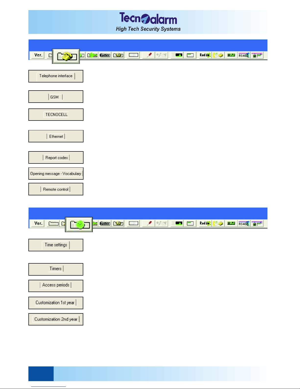
TELEPHONE SECTION CONFIGURATION
z Telephone interface: Programming of the channels from A to H, call back function,
commmunicator block, general settings
z GSM: Enabling of the GSM interface, answering mode, rings, airtime request, SMS
heading, GPRS settings, commands by SMS, password, white list
z Tecnocell: Enabling of the external GSM communicator, answering mode, emergency
phone number, association of the messages, emergency SMS, enabling of the guided
menu and of the data channel
z Ethernet: Configuration of the integrated 8 ports Ethernet switch, IP address, subnet
mask, gateway, programming of the communication port for the Local Server
Tecnoalarm, Remote Server Tecnoalarm, Tecnoserver Tecnoalarm, Tecno_Out
z Report codes: Programming of the report codes of all 8 channels for the event
transmission
z Opening message - Vocabulary: Test/recording/loading of the opening message,
loading and update of the vocabulary
z Remote control: Remote control message, alphanumerical description,
programming of the activation time
z Time settings: Entry time 1 and 2, exit time, disarming confirmation time, delay of
channel and siren activation, antimasking and power failure, alarm time, tamper,
technical and hold-up alarm time; duration of end of by-pass and automatic arming
warning, maximum duration of by-pass, supervision interval
z Timers: Frequency and moment of activation, association of the function
z Access periods: Frequency and moment of activation, association of the access
periods to the codes, transponders/RFID and remote controls
z Customization 1st year: Programming of the working days, holidays and holiday
eves, winter and summer time, viewing of the scheduled message on the console
z Customization 2nd year: Same as for the first year
TIME PARAMETER CONFIGURATION
Page 9
TP8-96 VIDEO - Installer manual
Introduction to the TP8-96 VIDEO system
1-3
ACCESS CONFIGURATION
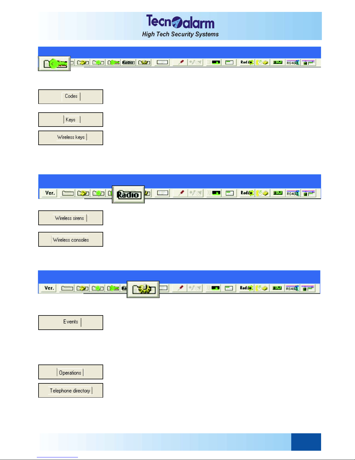
z Codes: Programming of the codes, name and length of the code, arming/disarming
function and by-pass, association to the programs, attributes
z Transponders: Programming of the transponders, name, arming/disarming function
and by-pass, association to the programs, attributes
z Wireless keys: Programming of the wireless keys, name, association of the keys to
the programs or the functions, attributes
z Wireless sirens: Alarm time, siren delay, flashing time, volume setting, functioning
mode
z Wireless consoles: Association of the program status LED to the programs, attributes
z Events ->Operations: When a specific event happens, the control panel executes a
specific operation associated to the event, e.g.:
• What kind of event? Arming
• Which arming? Remote arming
• By whom? User 1
• Which program? Program 2
• How? By telephone
z Operations: Creation of a new operation, operation modification, operation deleted
z Telephone directory: Association of specific telephone numbers to the operations
WIRELESS DEVICE CONFIGURATION
ADVANCED PROGRAMMING
Page 10

Introduction to the TP8-96 VIDEO system Installer manual - TP8-96 VIDEO
1-4
EVENT LOG
Viewing, printing and saving as a text file (TXT) of the control panel event log. The stored events are viewed with
indication of date and time. You can list the event log by date or type.
z N.: Event number. Click to list in chronological order (recording sequence)
z Date and time: Click to view the events of a determined period of time
z Description: Event description. Click to list the events by type and view the events of a
specific type
Hardware configuration of the system.
This menu permits addition or deletion of the hardware modules of the system.
z Add: Click on "add" to add the device selected in the list.
z Delete: Click on "delete" to delete the device selected in the list.
z Modules available: List of the modules available for the system.
HARDWARE CONFIGURATION
FLOOR PLAN CONFIGURATION
This menu allows to create and to manage the floor plans associated to the system.
This menu is only enabled if you have the corresponding Tecnoalarm license and the automatic wiring option is
disabled.
z Menu which permits the selection of the useful elements to create the floor plan.
For viewing specific commands are available.
z Symbols available: For floor plan configuration
Page 11
TP8-96 VIDEO - Installer manual
Introduction to the TP8-96 VIDEO system
1-5
RF MONITOR
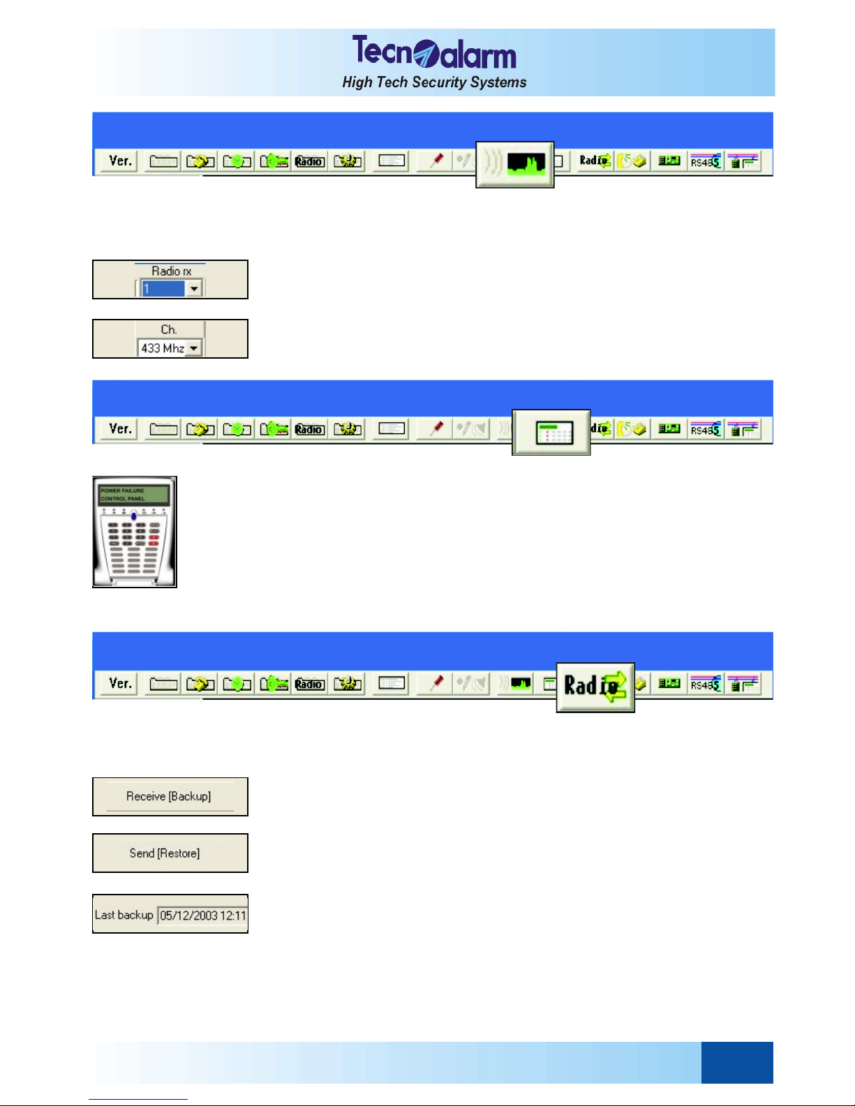
RF Monitor is a software instrument which permits the graphic presentation of the wireless data transmission.
It also permits measuring of the background noise in the place the control panel is installed.
This function is available only if the control panel is connected.
z Radio rx: Selection of the receiver to control.
z Ch.: Selection of the frequency channel to control.
It permits viewing of a virtual console to communicate with the control panel.
You can view the console only if the control panel is connected.
This menu allows to backup and restore the wireless device configuration.
This function is available only if the control panel is connected.
z Receive (backup): Reception and storage in the PC of the data relating to the
wireless devices from the control panel.
Backup (save a copy)
z Send (restore): Transmission of the data relating to the wireless devices which
have been saved before in the PC to the control panel.
Restore (recover the data)
z Last backup: Date and time of the last backup
VIRTUAL CONSOLE
BACKUP-RESTORE OF THE WIRELESS CONFIGURATION
Page 12
Introduction to the TP8-96 VIDEO system Installer manual - TP8-96 VIDEO
1-6
OPENING MESSAGE
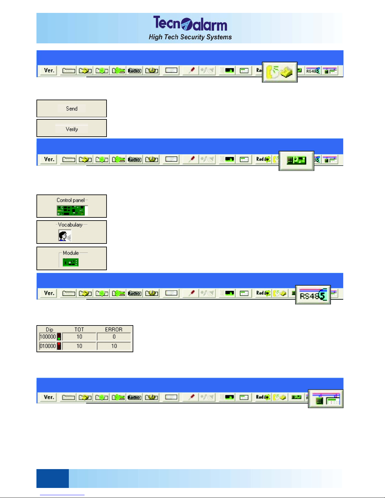
This menu allows to send the opening message programmed in the telephone menu to the control panel.
This function is available only if the control panel is connected.
z Send: Transmission (and storage) of the opening message to the control panel.
z Verify: Reproduction (listening) of the recorded opening message.
This menu allows to upgrade the vocabulary of the system and the firmware only for those devices which permit this.
This function is available only if the control panel is connected.
z Control panel: Allows to view and upgrade the firmware version of the control panel.
z Vocabulaire: Allows to view and upgrade the vocabulary.
z Module: Allows to view and upgrade the firmware version of the connected input
expansions.
Permits the analysis of the RS485 serial bus communication.
This function is available only if the control panel is connected.
z Dip: Logical address of the device
z TOT: Total number of transmissions
z ERROR: Number of communication errors
This menu allows to check the coherence between the programmed devices and the hardware actually installed. The
software automatically scans all the installed devices, it checks the coherence with programming and it signals any
possible incoherence.
This function is available only if the control panel is connected.
FIRMWARE AND VOCABULARY UPDATE
RS485 SERIAL BUS ANALYSIS
HARDWARE COHERENCE CONTROL
Page 13
TP8-96 VIDEO - Installer manual
Introduction to the TP8-96 VIDEO system
1-7
1.1 TP8-96 VIDEO CONTROL PANEL
8 zone inputs, expandible via RS485 bus until 96 (maximum 64 wireless zones), 6 programmable
outputs, 1 RS485 serial bus port (communication speed 38,4000 Baud), 1 Siren Bus port, GSM
module, 8 ports LAN Ethernet switch, 6.2A power supply
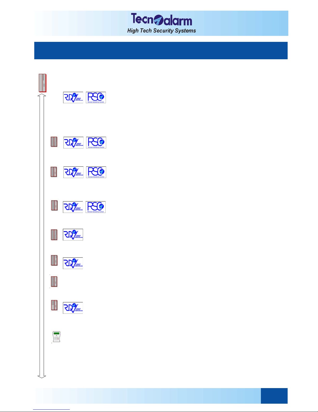
1.1.1 INPUT EXPANSIONS - MAX. 15
z SPEED ALM8 PLUS: Input expansions with power supply, 4 Sensor Bus inputs for 8 RSC
devices, 4 programmable outputs, 1 Siren Bus output for 8 sirens, 1.8A power supply
z SPEED 8 PLUS: Input expansions, 2 Sensor Bus inputs for 8 RSC devices, 2 programmable
outputs
z SPEED 4 PLUS: Input expansions, 1 Sensor Bus input for 4 RSC devices, 4 zone inputs,
1 programmable output
z SPEED ALM8: Input expansions, 8 zone inputs, 4 programmable outputs, 1.8A power supply
z SPEED 8: Input expansions, 8 zone inputs, 2 programmable output
z SPEED 8 STD: Input expansions, 8 zone inputs
z SPEED 4: Input expansions, 4 zone inputs, 1 programmable output
1.1.2 CONSOLE - MAX. 15
z LCD300/S
Console: LCD display with 2 lines of 16 characters, 32 signaling LED, 16 keys, integrated
speaker for voice synthesis
1.2 HARDWARE CONFIGURA TION- AVAILABLE MODULES
Page 14
Introduction to the TP8-96 VIDEO system Installer manual - TP8-96 VIDEO
1-8
1.1.3 WIRELESS EXTENSION - MAX. 2
z RX300/433868: Dual frequency wireless receiver (433MHz/868MHz), management of the
LCD300 WL wireless consoles and the SAEL 2000 WL wireless sirens
z RTX200/433868: Dual frequency wireless receiver-transmitter (433MHz/868MHz), bidirectional
management of the LCD300 WL wireless consoles and the SAEL 2000 WL wireless sirens
z LCD300 WL: Wireless console, LCD display with 2 lines of 16 characters, 16 keys, 1 NC alarm
input
z SAEL 2000 WL: Bidirectional dual frequency wireless siren
z TX240-3: Wireless key, 3 programmable function keys
1.1.4 CONTROL UNITS - MAX. 15
z TP SDN: Electronic keypad, 12 keys, 18 signaling LED, management of maximum 4 programs
z TP SK6N: Transponder reader with mini keypad, 10 signaling LED, management of maximum
6 programs
z TP SKN: Interface for the management of transponder readers. Each transponder reader
manages maximum 3 programs
1.1.5 GSM COMMUNICATOR- MAX. 1
z TECNOCELL PRO-PL: external GSM communicator; transmission via GSM network,
transmission of SMS messages and of voice messages. The device has no address.
z SPEED RS485: Serial bus extension; allows to increase the length of the serial bus by 1km.
The device has no address.
z STAR RS485: Serial bus extension, permits star-shaped connections, 3 RS485 loops, 6 lines.
The device has no address.
z SAEL 2000PRO BUSL: Self-powered outdoor siren with RSC technology. Max. 8 sirens can be
connected to the Siren Bus.
Page 15
TP8-96 VIDEO - Installer manual
Introduction to the TP8-96 VIDEO system
1-9
1.1.6 OUTPUT EXTENSIONS - MAX. 16
Page 16
Introduction to the TP8-96 VIDEO system Installer manual - TP8-96 VIDEO
1-10
Page 17
TP8-96 VIDEO - Installer manual
Introduction to the TP8-96 VIDEO system
1-11
Page 18
Introduction to the TP8-96 VIDEO system Installer manual - TP8-96 VIDEO
1-12
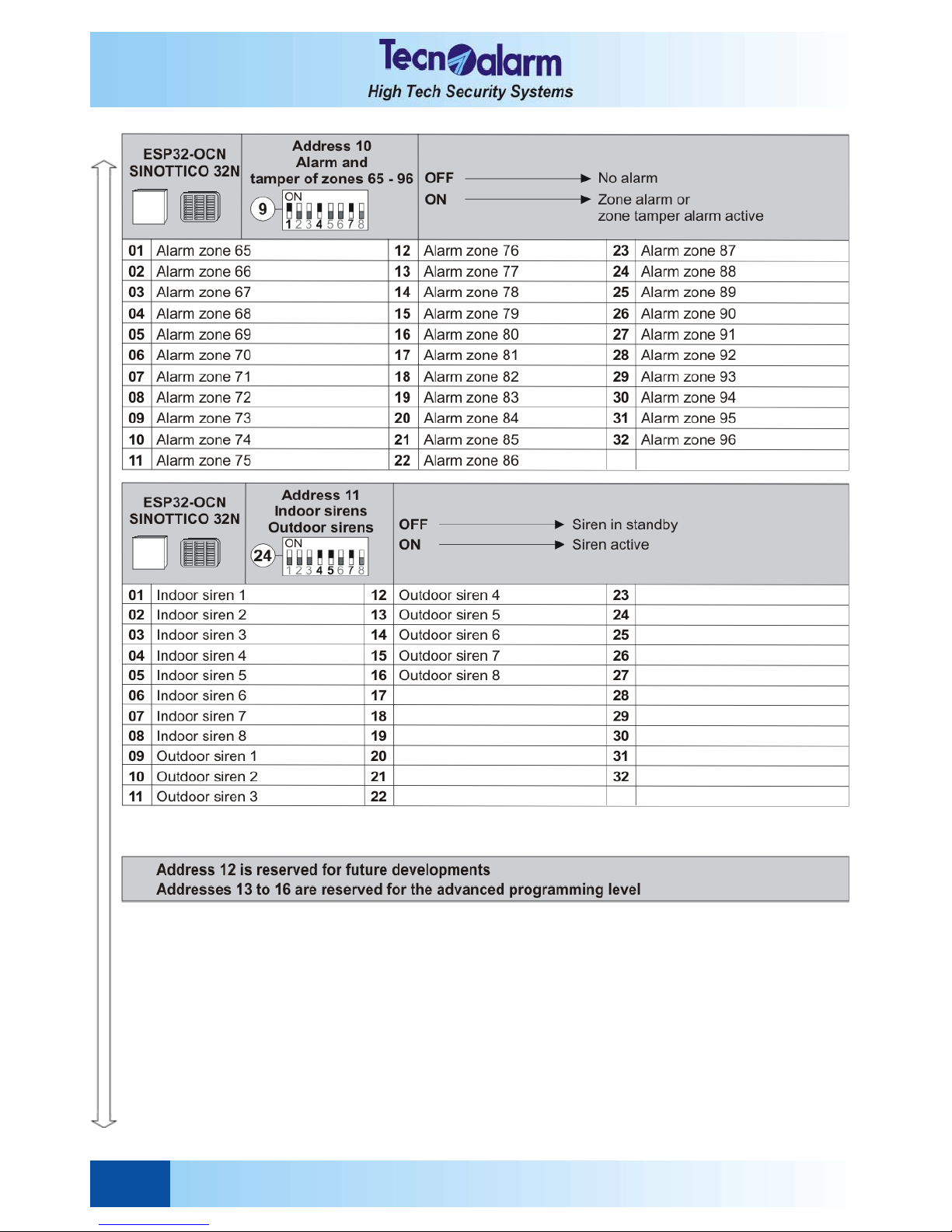
N.B.: The free (i.e. undefined) outputs are available for advanced programming.
Page 19
TP8-96 VIDEO - Installer Manual Programming of zones and programs
2-1
2. PROGRAMMING OF ZONES AND PROGRAMS
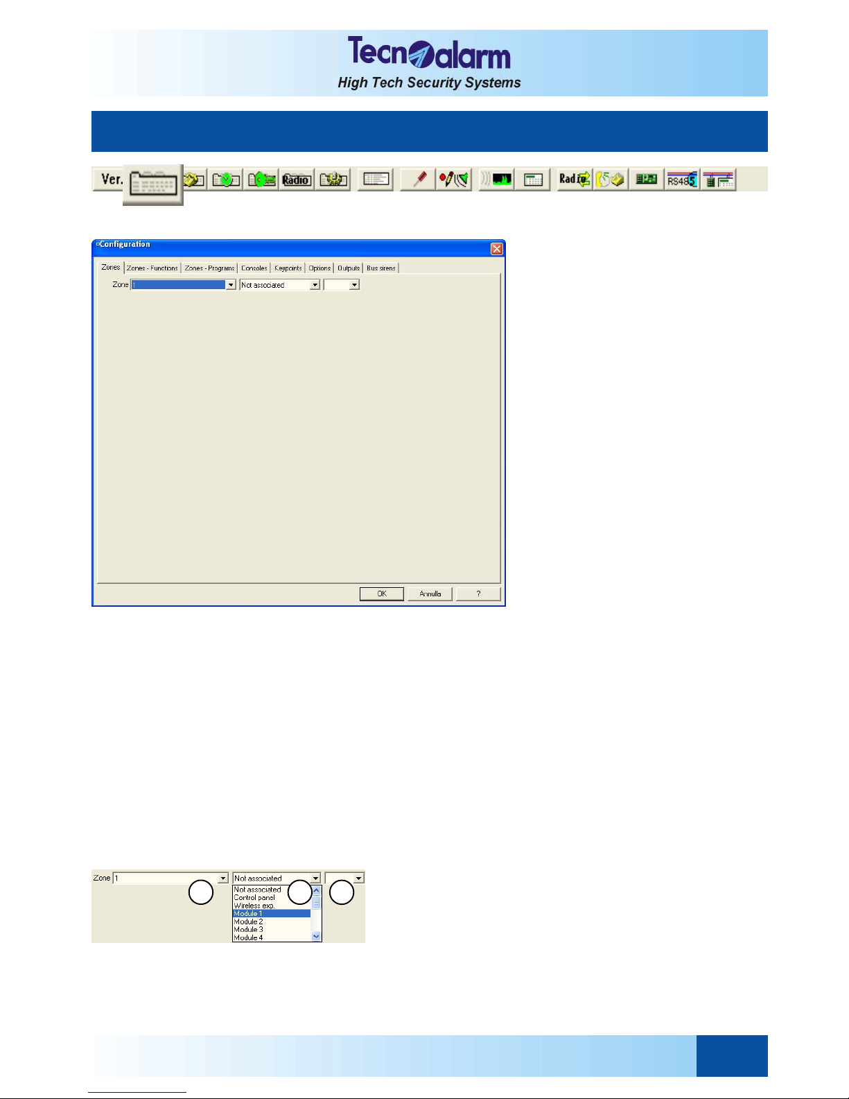
Permits the zone input configuration. Click on the above icon. On the screen is viewed:
The tables of the configuration zone permit to program the following parameters:
z List of zones controlled by the control panel, freely selectable among the modules connected and programming of
the zone parameters
z Zone-function association
z Zone-program association
z Association of the programs to the consoles
z Association of the programs to the secondary control units (key points)
z System options
z Logic output parameters
z Bus siren parameters
2.1 ZONE CONFIGURATION
2.1.1 CREATION OF ZONE LIST AND PARAMETERS
The TP8-96 VIDEO can control max. 96 zones. The zones can be associated to the zone inputs of the installed
hardware. The system configuration may provide more inputs than the control panel can control. It is for this raison, that
you have to choose the inputs to be controlled from those provided by the modules and draw up a zone list.
A Logic zone. Display the numerical list of the logic zones
managed by the control panel by clicking on the lateral arrow
and select the wished zone.
B Module. Display the device list with the zone inputs clicking
on the lateral arrow and select the wished device. The list is
composed of: Not associated (none device associated to the
logic zone), Control panel, Wireless exp. (espansion zone
radio), modules from 1 to 15 (wired zone extension).
C Module input. Display the numerical progressive list of the
physical zone available on the device precedently selected and
click on the wished zone input.
A
B C
Page 20
Programming of zones and programs Installer Manual - TP8-96 VIDEO
2-2
Once logic/physic zone association has been completed, the following items which caracterise the zones are viewed.
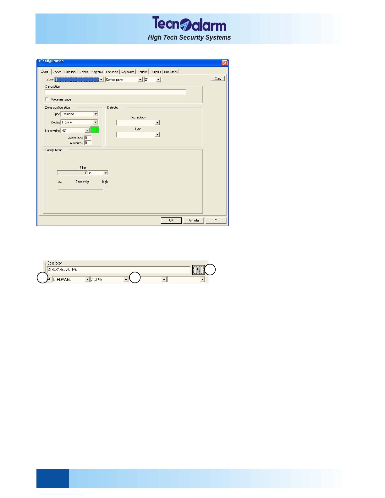
ASSOCIATION-COMPOSITION OF THE VOICE MESSAGE
It is possible to associate an individual description to the zone that will replace the zone number and identify the
program in every process. The zone description will be viewed on the display and announced by the speaker of the
console.
A Check Voice message item A to enable it.
B The voice message can be composed of max. 4 words selectable among those included in the vocabulary.
4 items are viewed, one for each word.
Click on the arrow of each item to scroll the vocabulary and select the word.
C At the end, click on the validation arrow C to memorize and play the message.
The words are automatically copied into the description line. It is possible to program the description manually
writing it directly in the description line.
Remember that the display of the console is able to view descriptions of maximum 16 characters. All further
characters will be cut off.
After the description association, programming of the zone continue according to the technology and type of
the selected detector. Each technology has specific programming parameters.
Repeat the procedure for every zone to be programmed (max. 96).
Press:
z OK to confirm and quit
z Abandon to quit without saving
COPY
Permits to copy the zone configuration if several zones must have the same configuration.
PASTE
Permits to paste the zone configuration copied. This icon is viewed only after clicking on copy. Select the zone
(association of logic zone to physical input of the module) and click on paste. The paste key shows a number which
corresponds to the number of the copied zone. It is sufficient to modify the desired parameters (e.g. the description).
B
C
A
Page 21
TP8-96 VIDEO - Installer Manual Programming of zones and programs
2-3
PROGRAMMING OF A STANDARD DEVICE
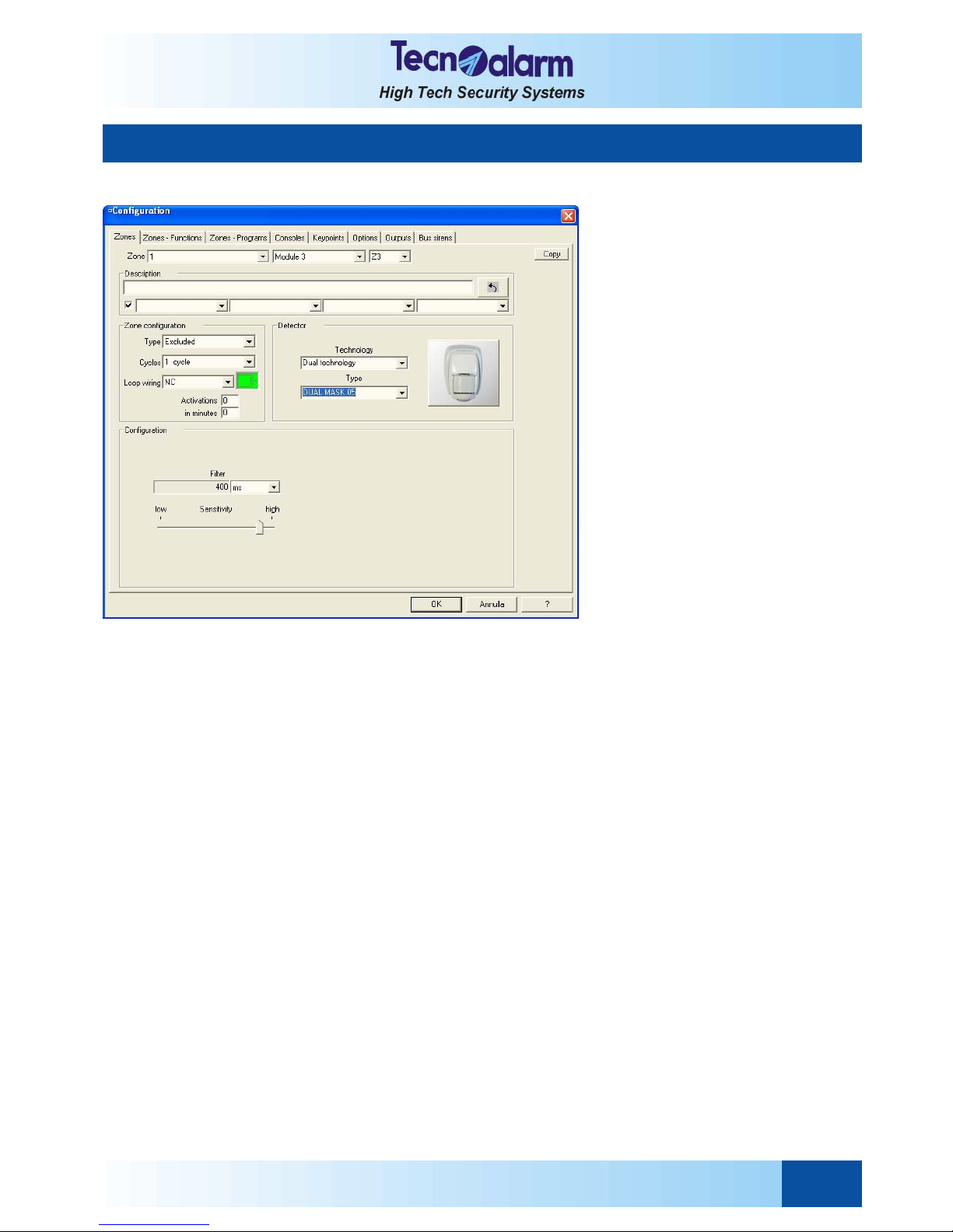
The first part of programming is identical to any other zone type. Select the Module (1 to 15) and a standard loop wiring
among the options available.
ZONES CONFIGURATION
z Type of zone
Click on the lateral arrow and select the type of zone between the following options:
• Excluded
The zone is permanently disabled from the detection of alarms.
• Direct zone
The zone is enabled for the detection of alarms immediately after arming of the program it is included in without
taking into account any entry or exit time (the zone is ready after 20 seconds).
• Walk through
The zone is a mixed zone. It is normally direct and enabled upon arming, but behaves as a delayed zone if
another delayed zone is in prealarm (entry time running) or during the exit time. It is used if one detector covers
more than one zone, e.g. entrance and hall, situated along the entry/exit path in which the walk through zone is
the more distant one.
• Technical
The zone is always enabled (even if the control panel is disarmed). It is used for the detection of gas leaks, fire
alarms or as expansion to the tamper line.
• Delayed T1 (exit time 1)
The zone is not enabled for the detection of alarms upon arming of the program it is included in but only after
expiry of the programmed exit time 1.
• Delayed T2 (exit time 2)
The same as above but with different exit time.
• Hold-up zone
The zone is always enabled (even if the control panel is disarmed). It releases a silent alarm (neither acoustic nor
optical signaling) with maximum priority.
• Key zone
The zone permits arming/disarming of the program it is included in by mechanical key or push button connected
to it. The functioning mode of the key zone can be programmed as on/off or pulse (see also the option window).
• Tamper zone
The zone is direct and always enabled (even if the control panel is disarmed). It is equivalent to the ZT input and
releases zone tamper alarms.
z Alarm cycles
Program the alarm cycles by clicking on the corresponding item and choose the number of alarm cycles. It is
possible to program 1, 4, 8, 15 or infinite alarm cycles prior to self-exclusion.
Page 22

Programming of zones and programs Installer Manual - TP8-96 VIDEO
2-4
z Contact type
Program the contact type of the zone input by clicking on the corresponding item and choose the contact type. The
contact type can be programmed as normally closed (NC), end-of-line resistor (BIL), double end-of-line resistor (B24)
or normally open (NO).
z Activations in minutes
The zone signals an alarm if the programmed number of the activations (0 to 99) has been counted during the
programmed period of time (0 to 99 minutes) or if upon expiry of the programmed period of time, the zone is
permanently in alarm.
DETECTOR
Permits association and configuration of the detector or contact by clicking on the correspondent item:
z Technology,
Determines the kind of detector or contact: dual technology, microwave, PIR, contact, inertia, pulse count, barrier,
24H and RDV
z Type
Select the type from the Tecnoalarm devices listed among the specified technology.
CONFIGURATION
z Filter
Determines the response time (ms, pulses, inertia, RDV) or sensitivity (from low to high) according to the kind of
the detector or contact selected.
z Sensitivity (filter value)
Determines the threshold according to which the control panel recognizes or not an alarm.
Move the scroll bar to change the filter value.
Unit and value
• ms 200, 400, 1000, 2000 ms Minimum time of the input must remain open to validate the alarm.
• Pulses 2, 4, 8, 16 impulses Minimum number of opening and closing of the input to validate the alarm.
The counter is reset after 15 seconds
• Inertia 12, 24, 36, 48 Minimum number of opening and closing of the input to validate the alarm.
• RD V 3, 5, 7, 10, 4 sensitivity levels for doppler microwave detectors
Repeat the procedure for every zone to be configured, then press:
z OK to confirm and quit
z Abandon to quit without saving
Page 23
TP8-96 VIDEO - Installer Manual Programming of zones and programs
2-5
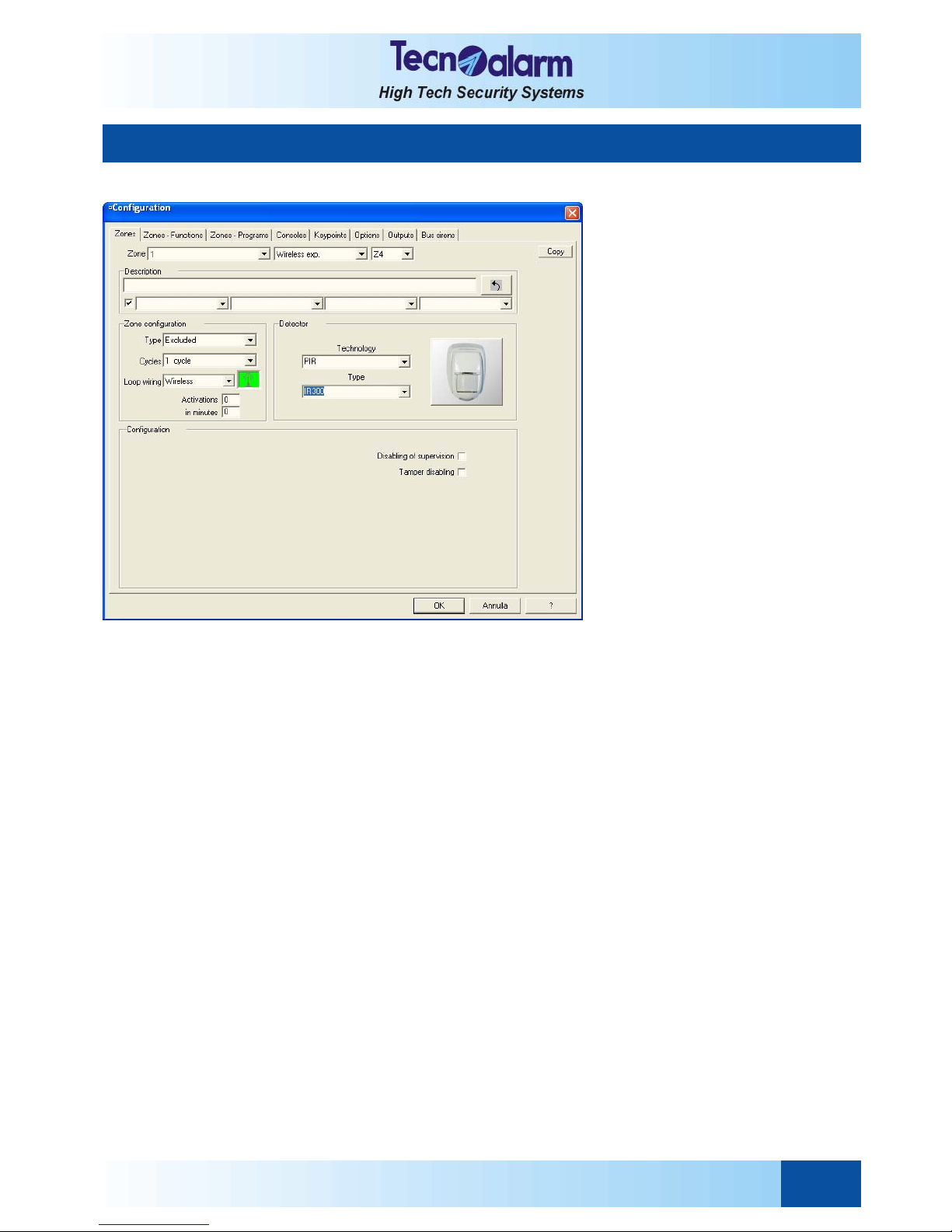
PROGRAMMING OF A WIRELESS DEVICE
The first part of programming is identical to any other zone type. Select the Wireless exp. and a wireless loop wiring
among the options available.
DETECTOR
Permits association and configuration of the detector or contact by clicking on the correspondent item:
z Technology
Determines the kind of detector or contact: PIR, contact, inertia, pulse count, barrier,
z Type
Select the type from the devices listed (IR100, IR200, IR300 or TRIRED WL)
CONFIGURATION
z Disabling supervision
Permits enabling and disabling of the supervision signaling.
Check the item to enable the function.
z Tamper disabling
Permits enabling and disabling of the anti-tamper protection.
Check the item to enable the function.
Repeat the procedure for every zone to be configured, then press:
z OK to confirm and quit
z Abandon to quit without saving
Page 24
Programming of zones and programs Installer Manual - TP8-96 VIDEO
2-6
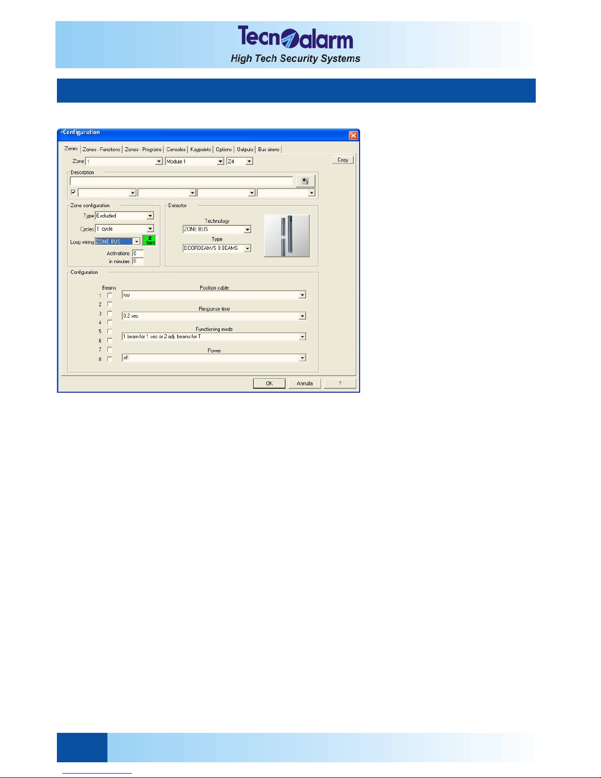
PROGRAMMING OF A DEVICE CONNECTED VIA ZONE BUS
The first part of programming is identical to any other zone type. Select the Module (1 to 15) and a Zone bus loop
wiring among the options available.
DETECTOR
z Type
Select the type from the devices listed (WINBEAM/S from 2 to 5 beams - DOORBEAM/S from 6 to 8 beams).
CONFIGURATION
z Beams
Permits enabling/disabling of determined beams (the flag indicates that the beam has been enabled).
z Position cable
Permits the selection of the cable position (top/bottom).
z Response time
Permits programming of the response time (T) of the device at two levels (0.2 seconds or 0.5 seconds).
z Functioning mode
Permits the definition of the modality of alarm detection:
• 1 for 1 sec. or 2 adj. for T
The alarm is released if any beam is interrupted for 1 second or two adjacent beams for the response time (T)
programmed.
• 2 adj. for T
The alarm is released if two adjacent beams are interrupted for the response time (T) programmed.
• 3 adj. for T lower part or 2 adj. for T
The alarm is released if three adjacent beams in the lower part of the barrier or two adjacent beams are interrupted
for the response time programmed.
• 1 for T
The alarm is released if any beam is interrupted for the response time programmed.
z Power
Permits programming of the beam power at four levels (off, low, medium, high).
Repeat the procedure for every zone to be configured, then press:
z OK to confirm and quit
z Abandon to quit without saving
Page 25
TP8-96 VIDEO - Installer Manual Programming of zones and programs
2-7
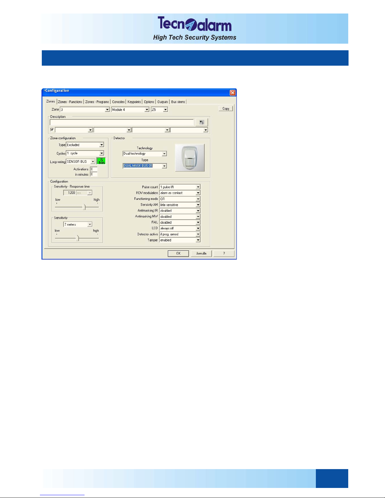
PROGRAMMING OF AN RSC DEVICE
The first part of programming is identical to any other zone type. Select the Module (1 to 15) and a Sensor bus loop
wiring among the options available. It follows an example of configuration of a motion detector.
DETECTOR
z Technology
Permits the selection of the detector technology among the options available (e.g. Dual technology)
z Type
Select the type among the devices listed (e.g. DUAL MASK BUS 05)
CONFIGURATION
z Sensitivity-Response time
Defines the response time of the detector to detect an alarm.
z Sensitivity
Defines the maximum range of the microwave detector (3, 5, 7, 10 or 15 meters).
z Pulse count
Defines the number of impulses (1 or 3 IR impulses) detected by the microwave before the alarm is released. The
timer is reset after 20 seconds from the first impulse (time-out).
z RDV modulation
• Alarm as contact Normal functioning
• RDV modul. in alarm RDV function. The detector sends a digital signal to the control panel which is directly
commensurate with the movement detected.
z Functioning mode
Permits programming of the functioning mode (OR or AND).
z Sensivity AM
Permits programming of the sensivity of the antimasking function (little or highly sensitive).
z Antimasking IR
Enabling/disabling of the antimasking function of the infrared section.
z Antimasking MW
Enabling/disabling of the antimasking function of the microwave section.
z Fail
Enabling/disabling of the sensor fault signal.
z LED
Programming of the LED:
• Always off the LED are never lit.
• Enabled the LED are lit if the program is armed and the detector has detected an intrusion.
Page 26

Programming of zones and programs Installer Manual - TP8-96 VIDEO
2-8
z Detector active
Defines if the detector is always active or only active if the system is armed.
z Tamper
Enabling/disabling of the anti-tamper protection.
Repeat the procedure for every zone to be configured, then press:
z OK to confirm and quit
z Abandon to quit without saving
Page 27
TP8-96 VIDEO - Installer Manual Programming of zones and programs
2-9
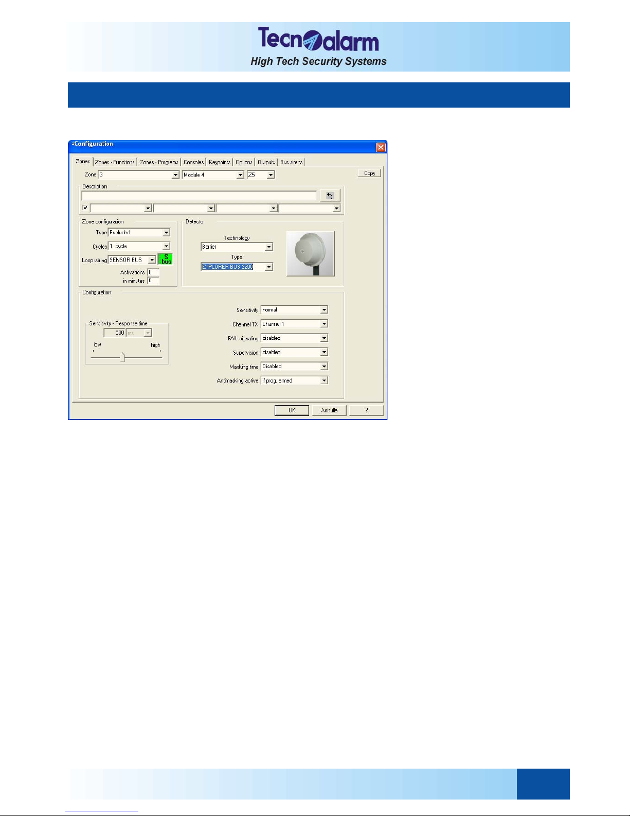
PROGRAMMING OF AN RSC DEVICE (continue)
The first part of programming is identical to any other zone type. Select the Module (1 to 15) and a Sensor bus loop
wiring among the options available. It follows an example of configuration ofa microwave barrier.
DETECTOR
z Technology
Permits the selection of the Barrier technology among the options available.
z Type
Permits the selection of the EXPLORER BUS 2200 type among the devices listed.
CONFIGURATION
z Sensitivity-Response time
Defines the response time of the detector at 5 levels (from 100 to 800ms)
z Sensitivity
Defines the maximum range of the microwave section at 5 levels (from very sensitive to very hard).
z Channel TX
Permits programming of the transmission channel (1 to 4). If the installation contains several copies, the TX channel
must be differentiated.
z FAIL signaling
Enabling/disabling of the barrier fault signal.
z Supervision
Enabling/disabling of the supervision function. Enabling is done only if the TX cable is connected with the RX one
(synchronism).
z Masking time
Permits programming of the time during which masking must persist so as to release the alarm (disabled, 10, 30 or
60 seconds).
z Antimasking active
Permits programming of the antimasking (always active or only active if the program is armed).
Repeat the procedure for every zone to be configured, then press:
z OK to confirm and quit
z Abandon to quit without saving
Page 28
Programming of zones and programs Installer Manual - TP8-96 VIDEO
2-10
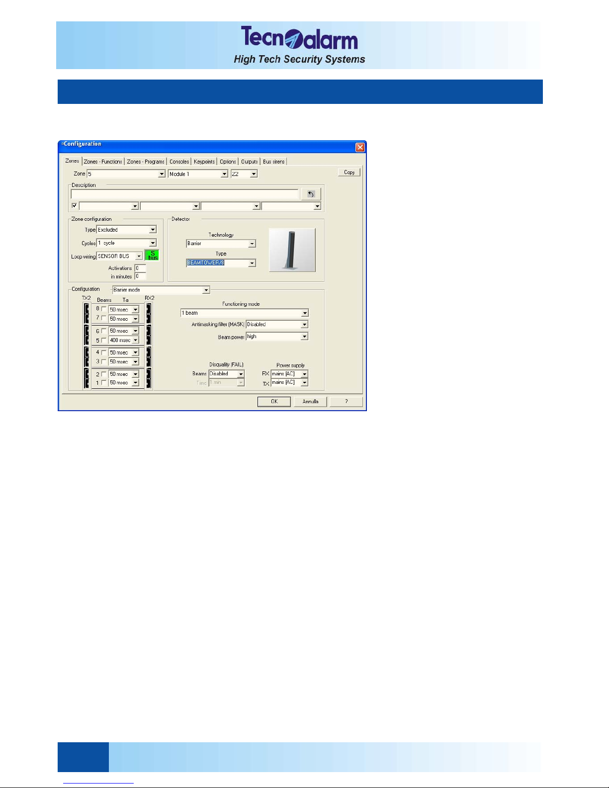
PROGRAMMING OF AN RSC DEVICE (continue)
The first part of programming is identical to any other zone type. Select the Module (1 to 15) and a Sensor bus loop
wiring among the options available. It follows an example of configuration of a PIR barrier.
DETECTOR
z Technology
Permits the selection of the Barrier technology among the options available.
z Type
Permits the selection of the type among the devices listed (BEAMTOWER/8 etc.)
CONFIGURATION
Permits the selection of the configuration of the installation. Select among the conventional barrier mode and 3 closed
and 6 open perimeter configurations.
z Beams
Permits enabling/disabling of a specific beam (the flag indicates that the beam is enabled). The beams are
numbered starting from the bottom.
z Ta
Permits programming of the beam interruption time at 4 levels (50, 150, 400ms or 1s). The Ta factor determines
part of the functioning mode.
z Functioning mode
Permits programming of the functioning mode. Select among 17 alarm detection modes.
z Antimasking filter (MASK)
Enabling/disabling of the antimasking function and programming of the time necessary to release the antimasking
alarm (disabled, 3, 30 or 120 seconds).
z Beam power
Permits programming of the beam power (high, medium-high, medium-low, low or automatic). Consider the
distance between transmitter and receiver and the environmental conditions.
z Disqualify (FAIL)
Enabling/disabling of the disqualification function. Permits programming of the number of disqualified beams
(disabled or from 1 to 8 beams) and the period of time (1, 5, 10 or 30 minutes) necessary to release the barrier
disqualified signal.
z Power supply
Defines the kind of power supply (AC or external DC) independently for TX and RX.
Repeat the procedure for every zone to be configured, then press:
z OK to confirm and quit
z Abandon to quit without saving
Page 29
TP8-96 VIDEO - Installer Manual Programming of zones and programs
2-11
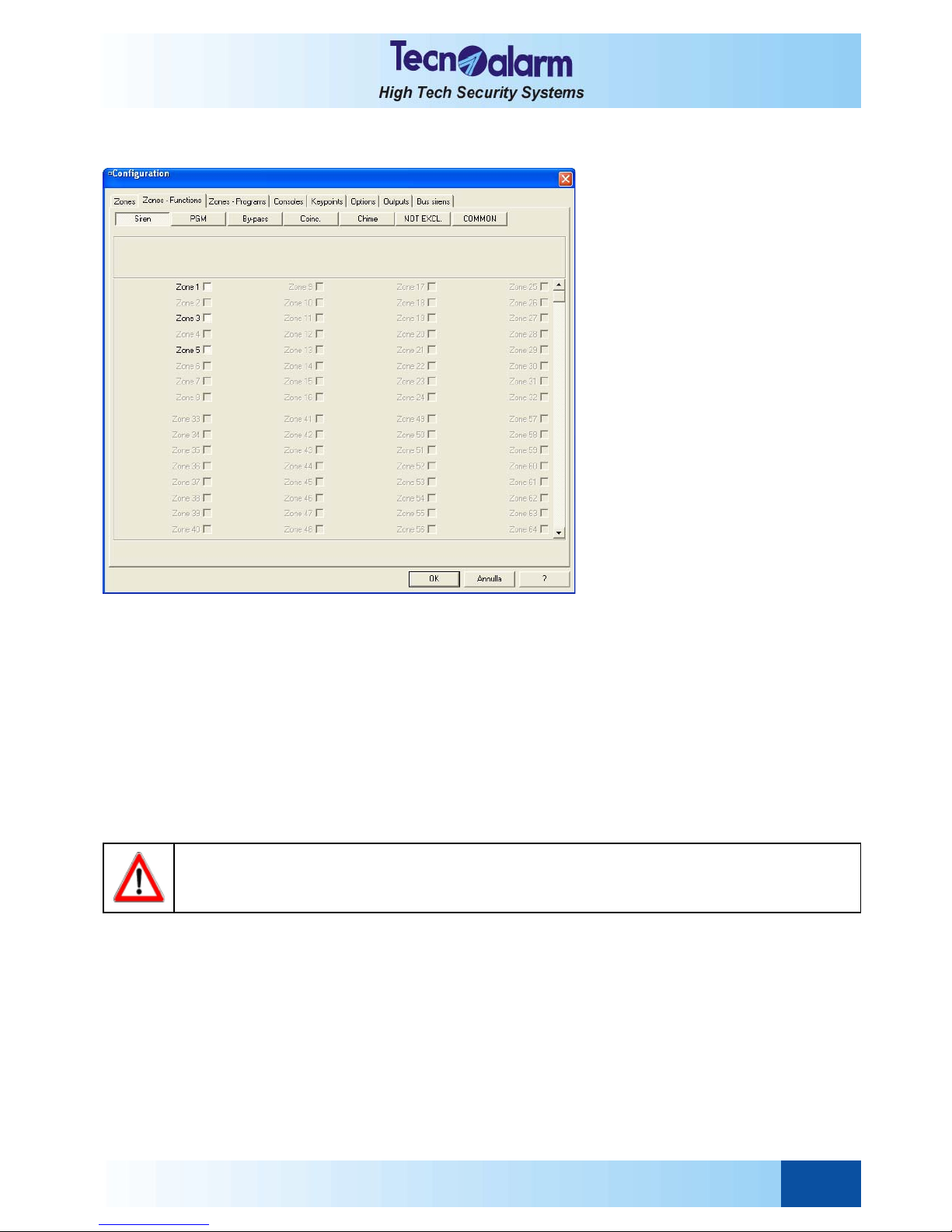
2.1.2 ZONE-FUNCTION ASSOCIATION
Open the zone configuration tables and select the Zone-Function window. On the screen is viewed:
The zone-function table permits the association of a series of functions to the zones:
z Siren
The checked zones cause the activation of the sirens in case of alarm.
z PGM
The checked zones cause the activation of the PGM logic output in case of alarm.
z By-pass
The checked zones associated are temporarily disabled from the detection of alarms, if the program they are
included in is armed and a by-pass code enabled for these zones (see also attributes of the codes) is entered.
The zones will be enabled again upon entering of the by-pass code or expiry of the by-pass time.
z Coinc.
The checked zones form a group of coinciding zones. Upon the detection of an alarm by one of the
coinciding zones the detector which has released the alarm is inhibited for 6 seconds and the control panel starts a
15 minutes timer. Two conditions are verified:
• If after 6 seconds but within 15 minutes another alarm is detected by the same zone, the alarm is released
(double knock).
• If within 15 minutes an alarm is detected by another coinciding zone the alarm is released.
z Chime
The checked zones are enabled for chime. Every time a chime zone is opened, if the program it is
included in is disarmed, the buzzer on the console and the logic outputs programmed are activated. The buzzer
on the console can be programmed so as to be activated for one 2 seconds beep upon every opening of the zone
input contact, or for a 3 seconds beep upon every opening which becomes continuous if the zone remains open (see
also the option window).
z Not excl.
The checked zones may in now way be excluded.
z COMMON
The checked zones form a group of common zones, i.e. they are included in several programs. As a consequence,
they are enabled for the detection of alarms only if all the programs they are included in are armed.
WARNING
Delayed zones may not be part of the group of coinciding zones.
Page 30

Programming of zones and programs Installer Manual - TP8-96 VIDEO
2-12
Select the function by clicking on the function key, then check the zones to be associated. The zones may be identified
either by the zone number or the description assigned during configuration.
Press:
z OK to confirm
z Abandon to quit without saving
Page 31
TP8-96 VIDEO - Installer Manual Programming of zones and programs
2-13
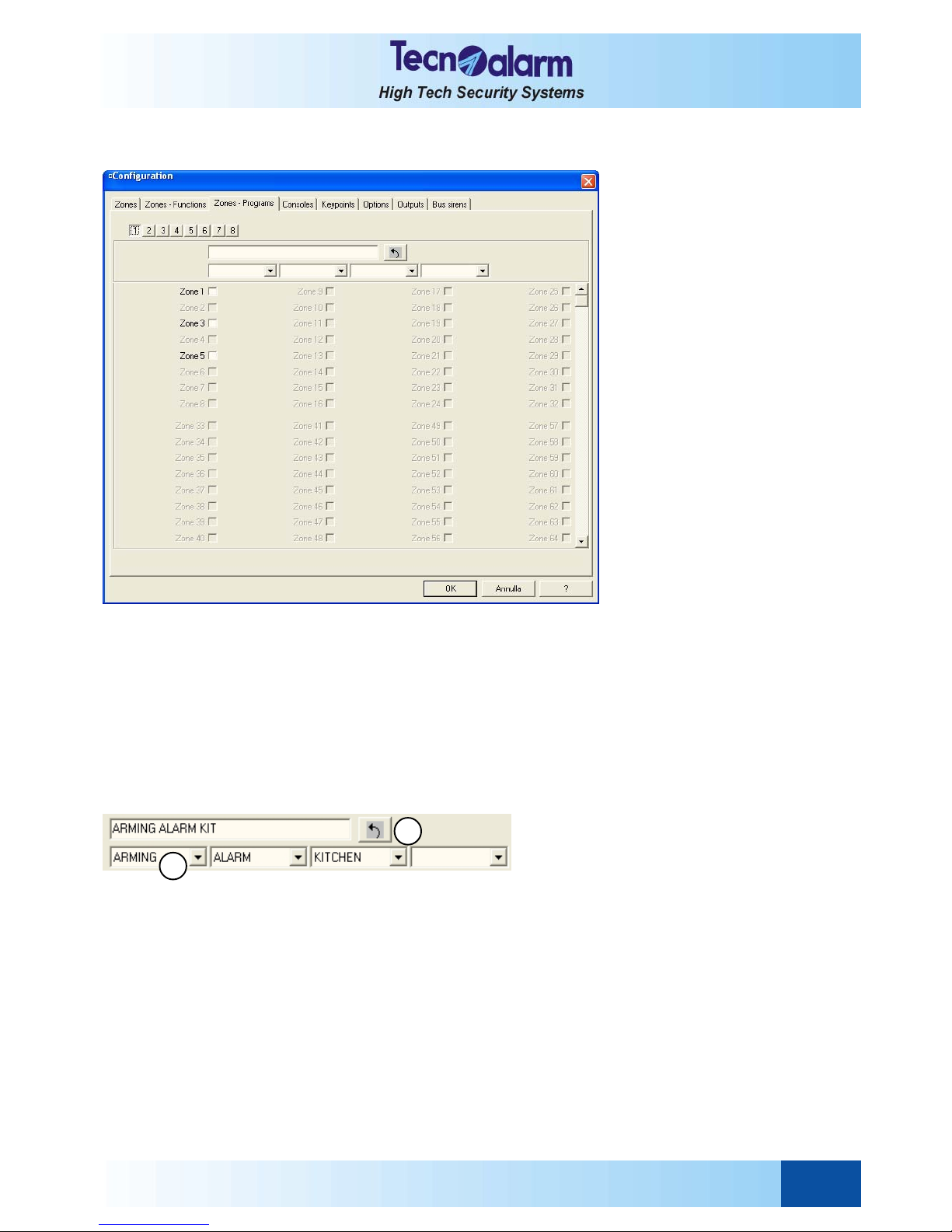
2.1.3 ZONE-PROGRAM ASSOCIATION
Open the zone configuration tables and select the Zone-Program window. On the screen is viewed:
The program configuration table permits the creation of max. 8 programs. The control panel can be armed through one
program at a time or several programs simultaneously. Every program groups a certain number of zones (1...96) that are
enabled/disabled contemporaneously on arming/disarming of the program (unless the program contains delayed or
common zones). If the program armed contains delayed zones, these are enabled for the detection of alarms only on
expiry of the exit time. If it contains common zones, these are enabled only if all the programs they are included in are
armed.
To associate the zones to the programs, select the program and then select the zones to be included in it by clicking
on the box beside the zone description. A program can contain max. 96 zones.
ASSOCIATION-COMPOSITION OF THE VOCAL MESSAGE
Select the program by clicking on the program number in question and check all the zones you wish to include.
It is possible to associate an individual description to the program that will replace the zone number and identify the
program in every process. The program description will be viewed on the display and announced by the speaker of the
console.
A The voice message can be composed of max. 4 words selectable among those included in the vocabulary.
4 items are viewed, one for each word.
Click on the arrow of each item to scroll the vocabulary and select the word.
B At the end, click on the validation arrow B to memorize and play the message.
The words are automatically copied into the description line. It is possible to program the description manually
writing it directly in the description line.
Remember that the display of the console views max. 16 digits. All further characters will be cut off.
Press:
z OK to confirm and quit
z Abandon to quit without saving
A
B
Page 32
Programming of zones and programs Installer Manual - TP8-96 VIDEO
2-14
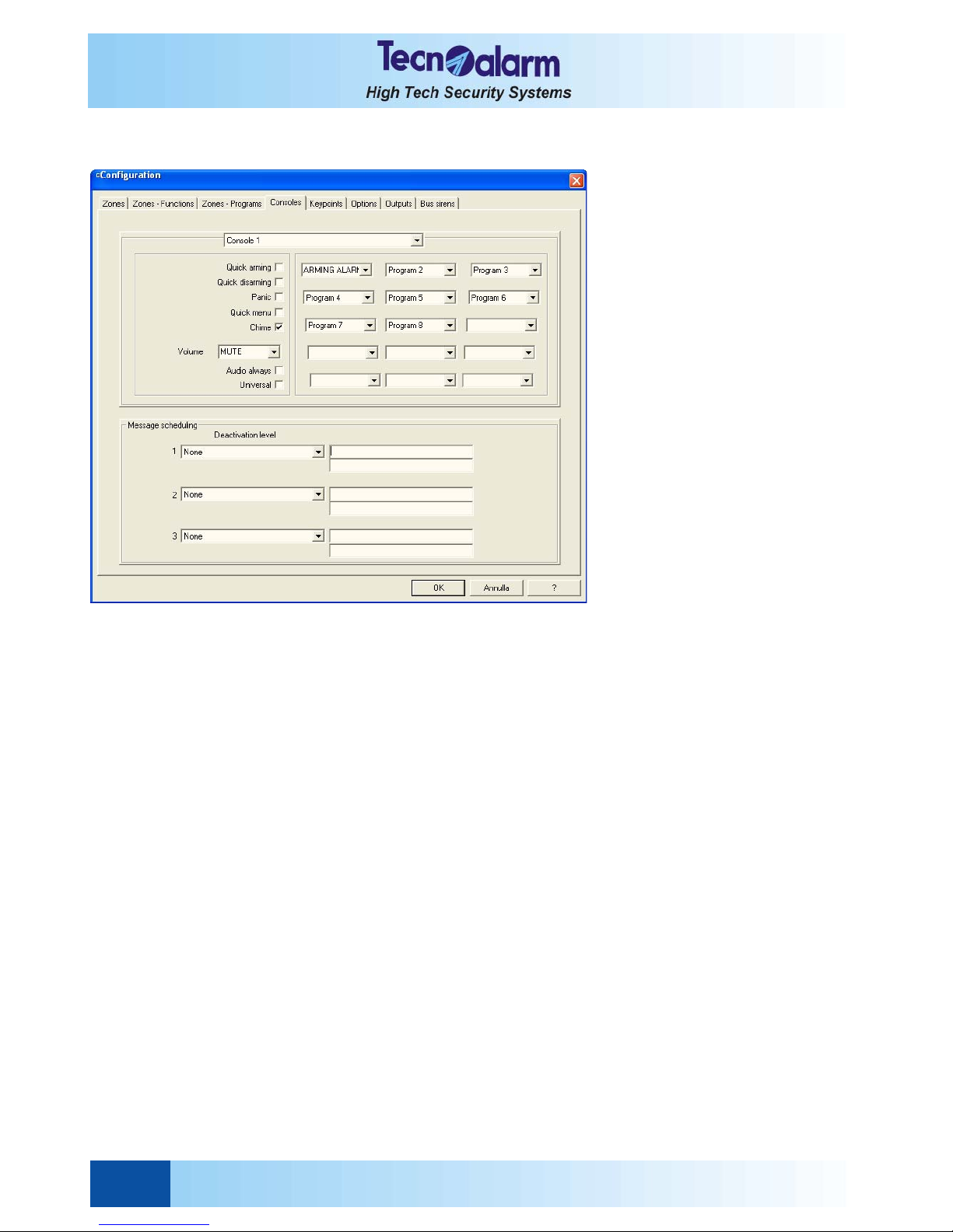
2.1.4 CONSOLES
Open the zone configuration tables and select the Console window. On the screen is viewed:
Select the console to be configured by clicking on the arrow next to the inscription Console 1 and scrolling the list.
Every console provides 15 couples of LED (status led and alarm LED) to view the status of the same number of
programs.
To associate a couple of LED to a determined program, click on the arrow next to the program number and select the
program (1 to 8) to be associated.
It is possible to define a series of functioning parameters of the console:
z Quick arming
z Quick disarming
z Panic
Panic alarm is released if the two arrow up and arrow down keys are pressed simultaneously on the console.
z Quick menu
Permits the activation/deactivation of the remote controls without entering any code.
z Chime
Permits enabling of the buzzer of the console for sending out a sound signal if the one of the chime zones is opened
and the program it belongs to is disarmed.
z Volume
The volume for the reproduction of the voice messages by the loudspeaker of the console can be set at four levels:
mute, low, moderate, high.
z Audio always
Enables the console for the reproduction of voice messages even if the relative operations (e.g. arming/disarming)
are executed by another console.
z Universal
Enables the console for the control of all the programs of the system, even those not associated to the LED. The
processes concerning the programs the status of which is not shown by the LED, will be viewed on the display.
Page 33
TP8-96 VIDEO - Installer Manual Programming of zones and programs
2-15
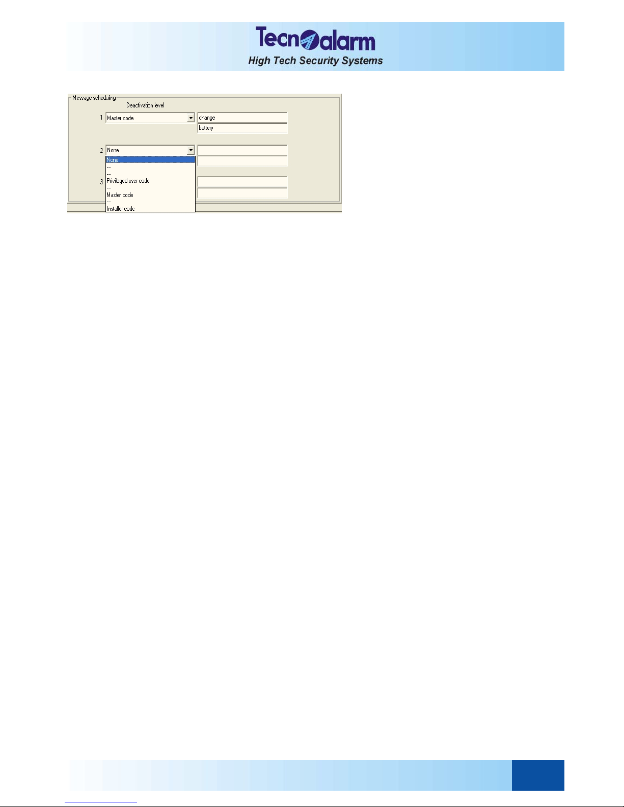
MESSAGE SCHEDULING
Permits programming of max. 3 messages that are viewed on the display of the console starting from a determined
date. The starting day is programmable through the system's calendar.
The same message can be viewed many time during the year.
Deactivation level
When the message is viewed on the console, it is possible to cancel it using the appropriate code only.
The code for deactivation are:
z None
z Privileged user code
z Master code
z Installer code
Press:
z OK to confirm and close the zone configuration tables
z Abandon to undo the configuration of the consoles
Page 34
Programming of zones and programs Installer Manual - TP8-96 VIDEO
2-16
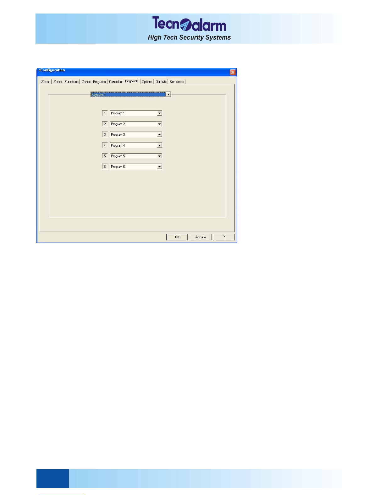
2.1.5 KEYPOINTS
Open the zone configuration tables and select the Keypoint window. On the screen is viewed:
Select the keypoint to be configured by clicking on the arrow next to the inscription Keypoint 1 and scrolling the list.
The keypoint configuration window permits the association of 6 programs and LED. But only the key reader with mini
keypad provides 6 LED to view the status of as many programs. The electronic keypad TP SDN provides 4 LED and the
key interface TP SKN pilots only 3 LED. By default the LED are always associated to the first programs of the system.
To associate a LED to a determined program, click on the arrow next to the program number and select the program
(1 to 8) to be associated.
Page 35
TP8-96 VIDEO - Installer Manual Programming of zones and programs
2-17
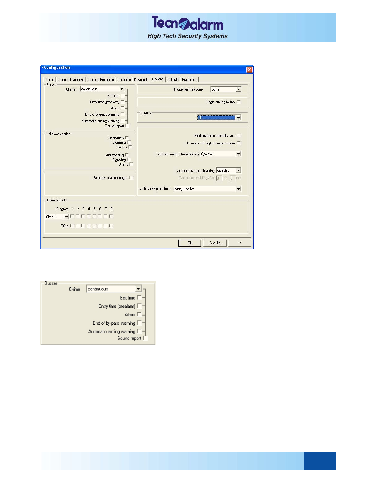
2.1.6 OPTIONS
Open the zone configuration tables and select the Option window. On the screen is viewed:
The option table permits to set the following system options:
BUZZER SECTION
The buzzer of the consoles can be actived for the following
operating conditions:
z Chime
The buzzer is activated if one of the chime zones is opened and
the relative program is disarmed.
• Continuous
The buzzer emits a 3s beep upon opening of the zone and
becomes continuous if the zone remains open.
• Pulse
The buzzer emits a 2s beep upon opening of the zone.
z Exit time
The buzzer is active during the programmed exit time.
z Entry time
The buzzer is active during the programmed entry time.
z Alarm
The buzzer is active during the programmed alarm time.
z End of by-pass warning
The buzzer is active during the time end-of-by-pass warning
displayed.
z Automatique arming warning
The buzzer is active during the time automatic arming is
displayed (arming timer).
z Sound report
Permits enabling/disabling of the voice report by the consoles. If
enabled, the above operating conditions are accompagnied by a
voice message.
Page 36
Programming of zones and programs Installer Manual - TP8-96 VIDEO
2-18
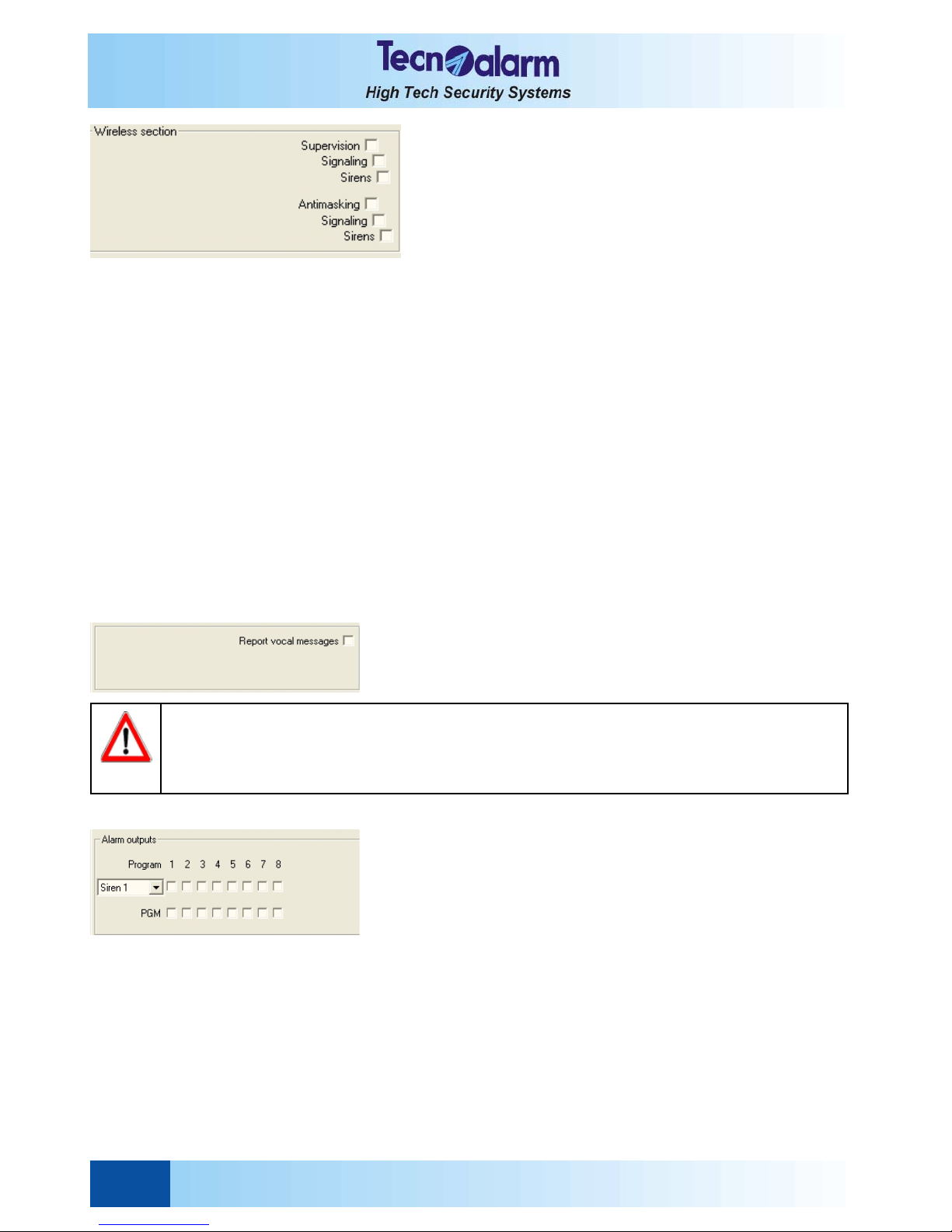
WIRELESS SECTION
Permits enabling and configuration of the supervision and
antimasking functions:
z Supervision
The supervision alarm is released if one of the wireless
devices omits the test transmission (and any alarm
signaling) for a period of time superior to the supervision
interval (see time parameters). The supervision alarm is
stored in the event buffer.
• Signaling
If enabled, in case of supervision alarm, on the console
is signaled trouble and possible programmed outputs
(supervisory boards and logic outputs) signal
supervision alarm.
• Sirens
If enabled, in case of supervision alarm, the sirens are
activated for the programmed tamper alarm time (see
time parameters).
z Antimasking
The antimasking alarm is released if the wireless receivertransmitter connected to the control panel detects a
jamming signal with the same frequency as the
transmission frequency of the wireless detectors, constant
for a period of time superior to the antimasking filter (see
time parameters). The antimasking alarm is stored in the
event buffer.
• Signaling
If enabled, in case of antimasking alarm, on the console
is signaled trouble and possible programmed outputs
(supervisory boards and logic outputs) signal
antimasking alarm.
• Sirens
If enabled, in case of antimasking alarm, the sirens are
activated for the programmed tamper alarm time(see
time parameters).
REPORT VOCAL MESSAGES
Permits enabling of the voice report by the console for all system
status and alarm signaling.
ALARM OUTPUTS
Permits the association of the programs to the siren output and
programmable logic output to be activated in case of alarm. Every
program can pilot independently:
z Logic siren 1 to 8
The logic siren is not bound to a physical siren but is activated
under determined conditions. Only in the programming section
of the outputs the logic siren is associated to a siren (indoor or
outdoor) output of one of the connected modules .
To select the logic siren click on the arrow next to the
inscription Siren 1 and scroll the siren list (1 to 8).
z Programmable logic output PGM
To associate the output to the programs check the item
beneath the program number.
WARNING
If the voice report is enabled it is recommended to disable the buzzer of the consoles in order to avoid
the superimposition of signaling.
To disable the buzzer of the consoles, use the dip-switch (dip 10) on the electronic boards of the
consoles.
Page 37
TP8-96 VIDEO - Installer Manual Programming of zones and programs
2-19
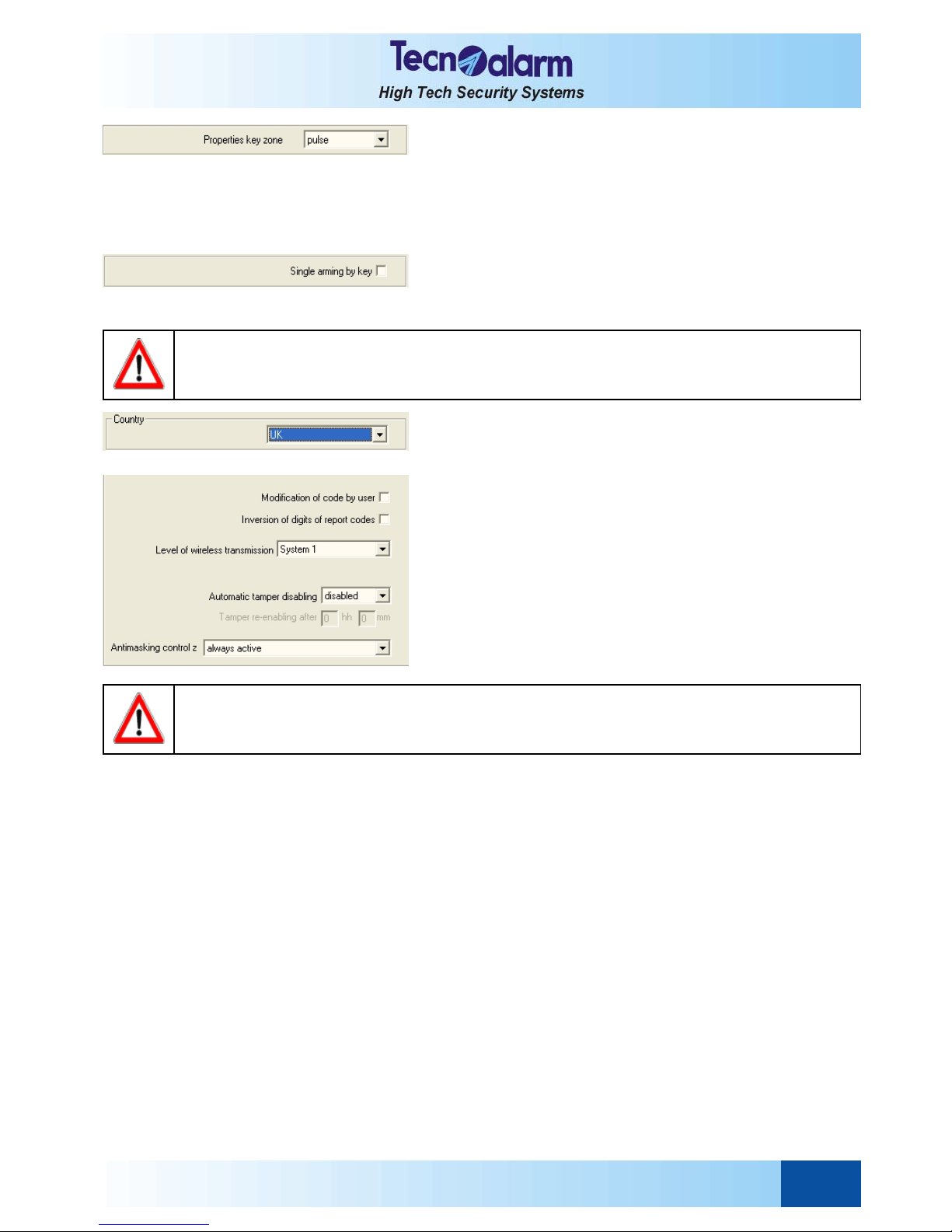
PROPERTIES KEY ZONE
The key zone can be set so as to work in the following way:
z ON/OFF
On/Off or switch functioning is indicated if an ON/OFF key is
connected to the key zone.
z Pulse
Pulse functioning is indicated if a push-button is connected
to the key zone.
SINGLE ARMING BY KEY
The keys can be enabled for merely single arming. In this way,
upon every introduction of the key into the key reader another
program it is enabled for will be selected whereas the previous one
is deselected.
COUNTRY
Permits to set the special versions depending on the country of
destination.
MODIFICATION OF CODE BY USER
By default the master code is the only one enabled for the
modification of the user codes. If the item is checked the standard
users are enabled for the modification of their proper code, but
cannot view nor modify the other codes.
INVERSION OF DIGITS OF REPORT CODES
Permits the inversion of the report codes to be sent during the
digital transmissions.
To be used only if specifically requested.
LEVEL OF WIRELESS TRANSMISSION
Every level of wireless transmission a different output power of the
wireless receiver-transmitter corresponds to.
AUTOMATIC TAMPER DISABLING
Permits the self-exclusion of the tamper alarms, if a determined
number of tamper alarms is counted in a determined period of time.
z Disabled
z Automatic tamper disabled after 1...255 alarms (cycles)
TAMPER RE-ENABLING AFTER
Permits programming of the period of time (in hour and minutes)
after which the tamper control is re-enabled.
ANTIMASKING CONTROL ZONE
Permits setting of the antimasking control of the zones:
z Always active
z Alarm if program armed
z Alarm and signaling if program armed
Check the corresponding item to enable the option, then press:
z OK to confirm and close the zone configuration
tables
z Abandon to undo the system option settings
WARNING
Valid for the key readers connected via key interface TP SKN only, but not for the key reader with
mini keypad TP SK6N.
WARNING
Prior to setting the level of wireless transmission check for possible output power limitation in your
country.
Page 38

Programming of zones and programs Installer Manual - TP8-96 VIDEO
2-20
2.1.7 OUTPUTS
Open the zone configuration tables and select the Output window. On the screen is viewed:
SELECTION OF THE HARDWARE MODULE
Click on the arrow to view the hardware modules with programmable outputs.
Select the module to be programmed.
OUTPUT-FUNCTION ASSOCIATION
For each module the programmable outputs are viewed:
z A Unprogrammable item. Shows the name of the physical output of the module.
z B Programmable item. Select the function clicking on the arrow.
z C Programmable item. Select functioning logic of the output in stand-by clicking on the arrow.
The output configuration table permits the configuration both of the functioning logic (normal/inverted) and the function of
the outputs of the control panel and the modules connected via serial bus.
To select the device click on the arrow next to Control panel [CPU] and scroll the list (control panel and module 1 to
15). The device number corresponds to the address programmed on serial bus.
A B C
Page 39
TP8-96 VIDEO - Installer Manual Programming of zones and programs
2-21
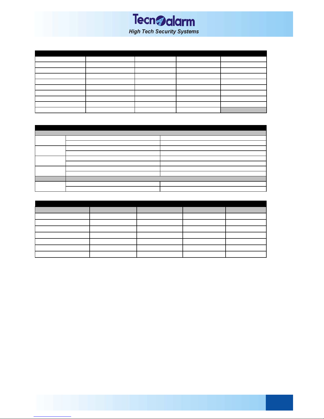
The logic outputs, according to programming, can have the following functions:
According to programming, the outputs can have the following functioning logic:
Press:
z OK to confirm and quit
z Abandon to quit without saving
St and-by Entry tim e (prealarm) Remot e cont rol 5 P rogram 7 Indoor siren 8
Fault PGM Remote c ontrol 6 P rogram 8 Outdoor s iren 1
Low battery A c c es s denied Remote cont rol 7 P anic Outdoor siren 2
Power failure Alarm Remot e cont rol 8 Indoor siren 1 Outdoor s iren 3
Tamper Sy s tem O K Program 1 Indoor siren 2 O utdoor si ren 4
Trouble M obile phone st atus P rogram 2 Indoor siren 3 Outdoor siren 5
Hold-up Remote cont rol 1 P rogram 3 Indoor s iren 4 O utdoor s iren 6
Technical Remot e cont rol 2 P rogram 4 Indoor siren 5 Outdoor siren 7
Chime Remot e c ontrol 3 P rogram 5 Indoor siren 6 Outdoor siren 8
Telephone line Remot e cont rol 4 P rogram 6 Indoor siren 7 Reserved 1 t o 16
PRO GRAM M ABL E LOG IC O UTP UT S
Output Standa rd function ing logic Reverse functioning logic
St and-by: + 13.8V Sta nd-by: high im pedanc e
Alarm : high im peda nc e Alarm : + 13. 8V
Stand -by: high im pedanc e Stand-by : GND (ground)
Alarm : G ND (ground) Alarm : high im pe danc e
Stand -by: high im pedanc e Sta nd-by: presenc e of negative
Alarm : pres enc e of negative Alarm : high im pe danc e
Stand -by: high im pedanc e Sta nd-by: + 13.8V
Alarm : + 13. 8V Ala rm: high im pedanc e
OUT3 TVCC
Stand -by: high im pedanc e Sta nd-by: + 13.8V
Alarm : + 13. 8V Ala rm: high im pedanc e
OUT2+
Ou tp u t d edi cate d to th e p o w e r sup p l y r ese t of th e c amer as. D efaul t = r emo te co n tro l 3 i n verte d
OUT4+
CPU board of the control pane l
SRA
SIR INT
OUT1-
Modules
SRA SIR INT OUT1 OU T2
SPEED ALM8 PLUS
xxxx
SPEED 8 PLUS
xx
SPEED 4 PLUS
x
SPEED ALM8
xxxx
SPEED 8
xx
SPEED 4
x
SPEED 8 STD
Output ex te nsion
s
Page 40
Programming of zones and programs Installer Manual - TP8-96 VIDEO
2-22
2.1.8 BUS SIRENS
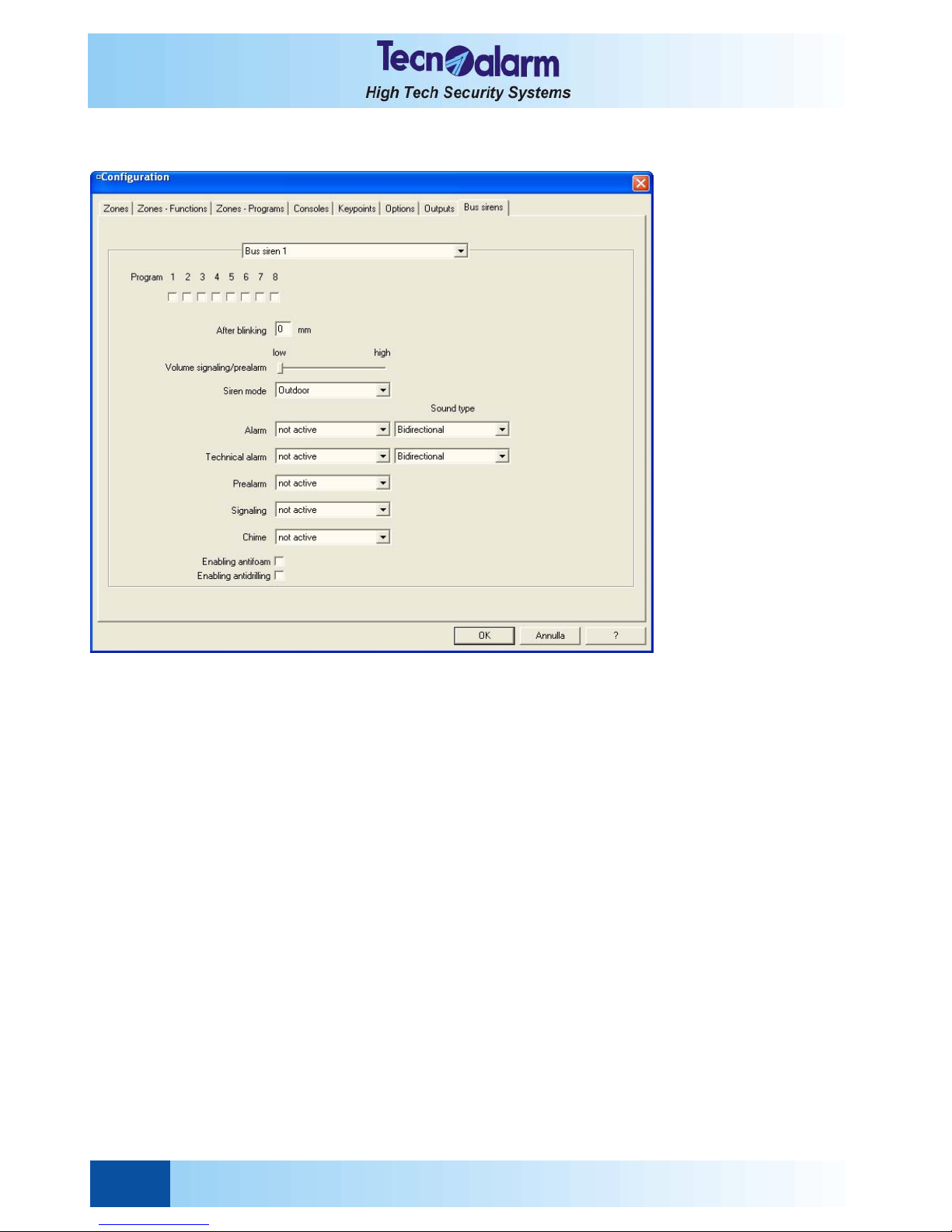
Open the zone configuration tables and select the Bus siren window. On the screen is viewed:
Permits to select the bus sirens (1 to 8) and to define their functions.
z Program
Permits the association of the selected bus sirens to the programs arming by the control panel (1 to 8).
z After blinking
Defines the time of blinking (in minutes) once the alarm ring is off.
z Volume signaling/prealarm
Defines the volume of the signaling (4 levels from low to high)
z Siren mode
The available functioning modes of the sirens are the followings:
• Outdoor Modes, time and volume typical of the outdoor siren
• Indoor Modes, time and volume typical of the indoor siren
z Alarm
The siren is activated when minimum one of the associated programs is in alarm (considering the time parameter
configuration) and in case of general alarm (tamper, trouble, etc.)
Sound type available:
• Bidirectional (default configuration)
• Monodirectional
• Bitone
z Technical alarm
The siren is activated if the technical zone is completely excluded from the programs or if it is included in one of the
associated programs.
Sound type available:
• Bidirectional (default configuration)
• Monodirectional
• Bitone
z Prealarm
The siren is activated if minimum one of the associated programs is in prealarm.
The sound type is fixed.
z Signaling
The siren is activated if the associated programs are armed/disarmed.
The sound type is fixed.
Page 41

TP8-96 VIDEO - Installer Manual Programming of zones and programs
2-23
z Chime
The siren is activated if the chime open zone is completely excluded from the programs or if it is included in one of
the programs associated to the siren.
The sound type is fixed.
z Enabling antifoam
Permits enabling/disabling of the antifoam optical protection.
z Enabling antidrilling
Permits enabling/disabling of the antidrilling protection.
z Activation mode
Determines the activation mode of the siren when the control panel detects an alarm:
• Not active The siren is not active
• Sounding Only the sound is activated
• Flashing light Only the flashing light is activated
• Sounding+ Flashing light Sound and et flashing light are activated
Check the corresponding item to enable the option, then press:
z OK to confirm and quit
z Abandon to quit without saving
Page 42

Programming of zones and programs Installer Manual - TP8-96 VIDEO
2-24
Page 43
TP8-96 VIDEO - Installer Manual Programming of telephone section
3-1
3. PROGRAMMING OF TELEPHONE SECTION
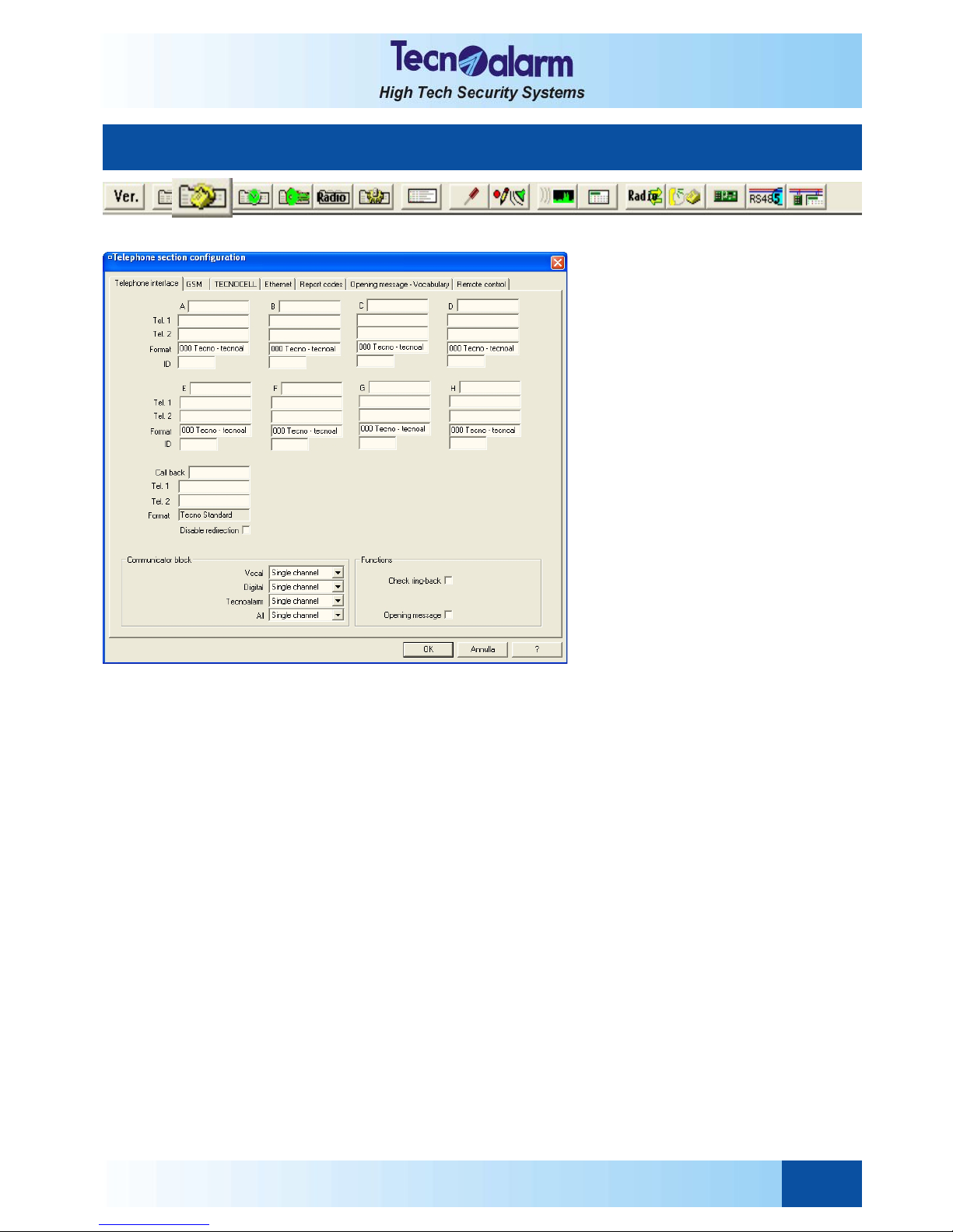
Permits programming of the telephone section. Click on the above icon. On the screen is viewed:
The telephone configuration tables permit programming of the following parameters:
z Telephone channels and general telephone parameters
z GSM module (internal)
z External GSM telephone communicator
z Ethernet switch
z Report codes
z Opening message-Vocabulary
z Voice messages and activation time of the remote controls
3.1 TELEPHONE PARAMETER CONFIGURATION
3.1.1 TELEPHONE CHANNELS AND STANDARD TELEPHONE PARAMETERS
The control panel is able to transmit alarm signaling or other data using either digital protocols or pre-recorded vocal
messages (composed of words of the vocabulary).
It can transmit and receive alarm signaling using the digital Tecnoalarm protocol or the most frequently used digital
protocols. Programming upload and download is possible using the Tecnoalarm protocol only.
The incorporated telephone interface provides 8 channels (A, B, C, D, E, F, G, H) individually programmable with a
description, a principal and a reserve telephone number, the transmission protocol and the ID code. Furthermore, it is
possible to determine the channels to be blocked on reception of the corresponding command, i.e. vocal, digital
Tecnoalarm, all, singularly or simultaneously.
The principal telephone number is always called first and the reserve one is only called in case there is no answer or if
the line is busy.
The user can block the telephone channels by clicking on the * key of the telephone.
It is possible to define which channels are affected by the block.
Page 44
Programming of telephone section Installer Manual - TP8-96 VIDEO
3-2
TELEPHONE CHANNELS
For each telephone channels it is possible to program the following
parameters:
z A...H
Description which identify the channel (max. 14 digits).
z Tel. no. 1
The principal telephone number that will always be called first
(max. 24 digits).
z Tel. no. 2
Reserve telephone number that will be called if there is no
answer to the principal number or the line is busy
(max. 24 digits).
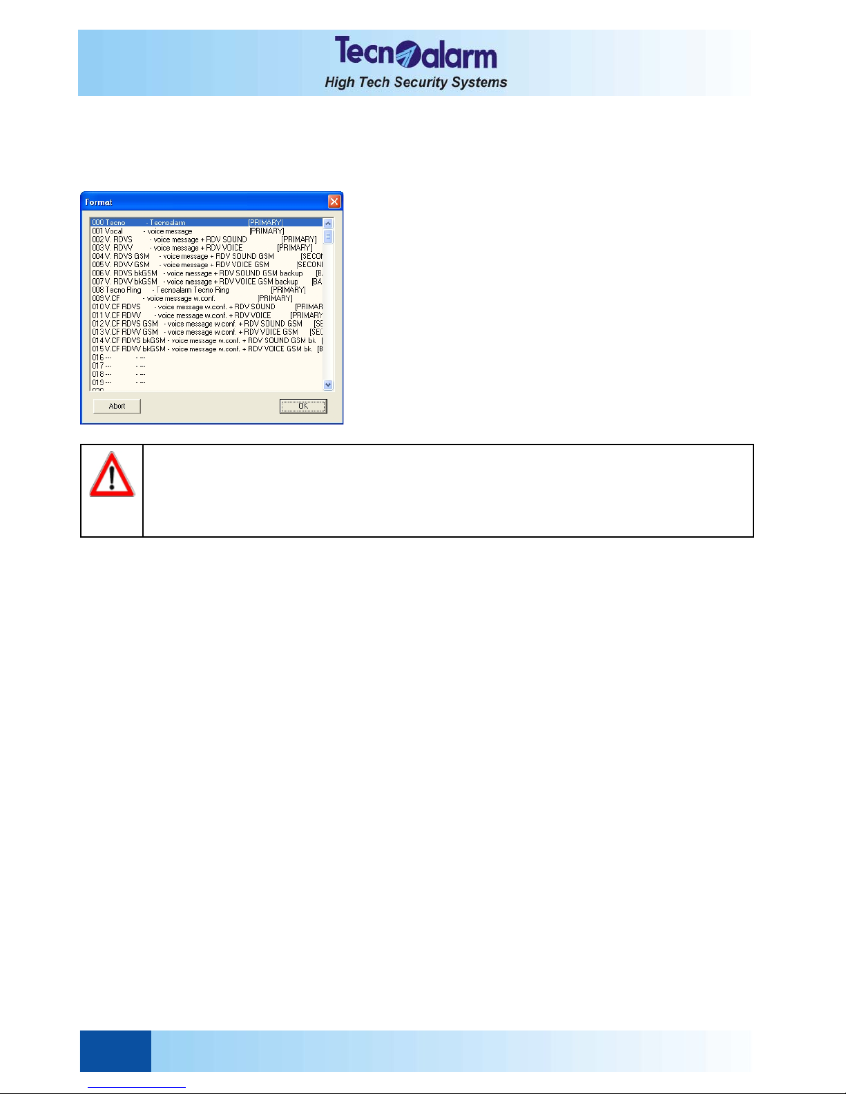
z Format
The transmission protocole is identified by a 3-digits code. All
the channels are programmed by default with the digital
Tecnoalarm protocol (000 Tecno).
By clicking on Format, the beside image is viewed.
z ID
The identification code is a code with 2 to 6 digits which
permits the connection of the control panel to different
monitoring stations (requiring ID codes of different length), i.e. a
monitoring station can require the 1234 code while another
monitoring station may expect 223344.
Repeat the same procedures for each telephone channels to be
programmed.
CALL-BACK
The call-back numbers are indispensable for remote programming of the control panel. When the installer tries to
connect to the control panel via telephone line, the onboard telephone section interrupts the communication after an
initial data exchange and calls one of the call-back numbers (starting with the first one).
The numbers should correspond to the installer or monitoring station authorized for remote programming. This
mechanism has been developped as a protection of both the user and the installer against attempts at sabotage.
The first callback number is always called first. The second one is only called if the first call is unsuccessful (line busy
or no answer). If both calls are unsuccessful, another four attempts are made alternating the first and second callback
number.
z Call back
Description which identify the owner of the call bac numbers, i.e. installer (max. 14 digits)
z Tel. no. 1
The first call back number is always the first to be called (max. 15 digits).
z Tel. no. 2
The second call back number is called if there is no answer to the principal number or the line is busy
(max. 15 digits).
z Format
The protocol for callback communications is unchangeable, i.e. digital Tecnoalarm format (00 Tecnoalarm).
z Disable redirection
The redirection of callback permits the execution of return calls to a telephone number different from those entered in
the telephone configuration window. Using the programming and monitoring software it is infact possible to enable
the redirection of callback and program a callback number in the software configuration (icon with PC and the 3 blue
keys).
Check the corresponding item to disable the function.
COMMUNICATOR BLOCK
The telephone channels are classified by the kind of protocol they use, i.e. the voice protocol, the special digital format
developped by Tecnoalarm or one of the most common digital formats.
The telephone section of the control panel can be set so as to block the specified channels upon reception of the
blocking command (* on the telephone dial).
According to programming, the communicator block affects either the vocal, digital or Tecnoalarm channels or all three
and this either singularly or altogether:
WARNING
It is compulsory to program the ID code of the channel.
All the channels have the same priority. The alarm are transmitted in chronological order starting with
channel A. The only exception is the hold-up alarm. If a transmission of another alarm is in course,
the active alarm call is interrupted to execute immediately the call for hold-up. At the end of the alarm
call, the previous call is restarted. From that onwards, the normal order continues.
Page 45
TP8-96 VIDEO - Installer Manual Programming of telephone section
3-3
z Vocal
The communicator block affects only those channels transmitting voice messages.
• Single channel
Upon reception of the blocking command the active call is interrupted and the alarm call cycle of the active voice
channel is blocked.
• All channels
Upon reception of the blocking command the active call is interrupted and the alarm call cycles of the active voice
channel as well as all the other voice channels programmed for the event are blocked.
z Digital
The communicator block affects only those channels using digital non-Tecnoalarm formats.
• Single channel
Upon reception of the blocking command the active call is interrupted and the alarm call cycle of the active digital
channel is blocked.
• All channels
Upon reception of the blocking command the active call is interrupted and the alarm call cycles of the active digital
channel as well as all the other digital non-Tecnoalarm channels programmed for the event are blocked.
z Tecnoalarm
The communicator block affects only those channels using the digital Tecnoalarm format.
• Single channel
Upon reception of the blocking command the active call is interrupted and the alarm call cycle of the active digital
Tecnoalarm channel is blocked.
• All channels
Upon reception of the blocking command the active call is nterrupted and the alarm call cycles of both the active
and all the other digital Tecnoalarm channels programmed for the event are blocked.
z All
The communicator block affects all the telephone channels independently from the protocol they use.
• Single channel
Upon reception of the blocking command the active call is interrupted and the alarm call cycle of the active channel
is blocked.
• All channels
Upon reception of the blocking command the active call is interrupted and the alarm call cycles of the active and
all the other vocal and digital channels programmed for the event are blocked.
FUNCTIONS
z Check ringback
If enabled, the control panel waits for the ringback tone before it transmits a message.
z Opening message
This function is valid only for the voice protocols.
If the function is enabled, the control panel transmits the opening message before the alarm message. If the function
is disabled, the control panel transmits only the alarm message.
See § 3.2 for explanatory notes.
Press:
z OK to confirm and quit
z Abandon to quit without saving
WARNING
The voice channel can be blocked only by pressing the key * or # on the telephone dial.
Any voice command is ignored.
WARNING
The digital non-Tecnoalarm protocols are to devide in single type and multiple type protocols.
In any case, both if a single type protocol is programmed or not, the other events are transmitted. No
event will be lost due to the communicator block!
Single type protocols transmit one event at a time, i.e. they close down the communication once the
event has been transmitted and recall to transmit the next one. The multiple type protocols transmit
the entire queue of events before they close down the communication.
Page 46
Programming of telephone section Installer Manual - TP8-96 VIDEO
3-4
3.1.2 GSM MODULE
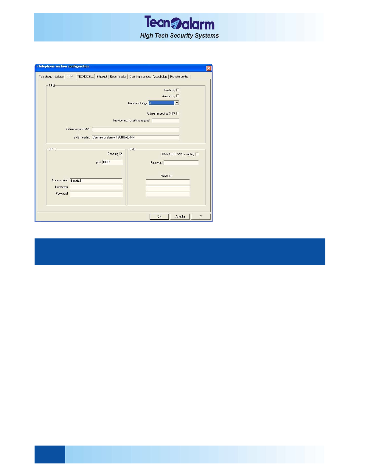
Open the telephone configuration tables and select the GSM window. On the screen is viewed:
If prepaid SIM cards are used, some of the mobile service providers allow to request the remaining airtime request via
SMS message.
GSM
z Enabling
Permits enabling/disabling of the integrated GSM module functions.
z Answering
If checked, after the programmed number of rings, the GSM telephone communicator answers to incoming calls
introducing the telephone guided menu.
z Number of rings
Number of rings prior to answering to incoming calls programmable from 3 to 15. By default, the GSM telephone
communicator answers after 3 rings.
z Airtime request by SMS
If checked, enables the remaining airtime request via SMS message as an alternative to the telephone call.
z Provider No. for airtime request
The telephone number the service provider has reserved for receiving the SMS with the remaining airtime request.
REMAINING AIRTIME REQUEST VIA SMS MESSAGE
If the provider offers this kind of service, once the provider number and (the case being) the airtime request by SMS
have been programmed, it is possible to check the remaing airtime via SMS message proceeding as follow:
Send an SMS message with the text "CREDIT" (respecting capital letters) to the telephone number of the
prepaid SIM card of the control panel.
On reception of the SMS message, the control panel interrogates the remaining airtime by sending an SMS
message to the programmed provider number.
On reception of the SMS with the remaining airtime from the provider, the control panel transmits the SMS
message to the mobile phone number used for the request.
z Airtime request SMS
Text of the message for the airtime request (max. 40 digits).
z SMS heading
The SMS sent by the control panel are automatically composed by the system. To distinguish the origin of the
messages (sender), it is possible to program an SMS heading (max. 40 digits without accents).
Since the English manuals are used in an extremely vast geographical area, involving a hudge number of mobile
phone providers and a great diversity in airtime management, it is understood that we cannot go into details. Thus,
we will confine ourselves to explaining the functions without stating any examples.
Page 47
TP8-96 VIDEO - Installer Manual Programming of telephone section
3-5
GPRS
z Enabling
Permits enabling/disabling of the GRPS channel functioning of the integrated GSM module.
z Port
Access to the Tecnoalarm Tecnoserver. The default value is 10001.
z Access point
Defines the access point to the network. The GPRS connection is not like a telephone line, but similar to the
Ehernet connection. The connection is made via Internet network. Therefore, it is necessary to enter the network
through an Access point. The access parameters are provided by the telephone service provider.
z Username
z Password
SMS
z COMMANDS-SMS enabling
Permits enabling/disabling of the remote control management by SMS.
z Password
Password (max. 8 alphanumerical digits) to be included in the SMS.
z White list
List of the telephone numbers enabled for the SMS commands.
If the white list contains telephone numbers, the control panel accepts the SMS commands only from the
programmed numbers. If no number has been programmed in the white list, the control panel accepts the SMS
commands from any telephone number.
See § 3.2 for explanatory notes.
Press:
z OK to confirm and quit
z Abandon to quit without saving
WARNING
Since the international prefix is not considered by the control of the number, it is not necessary to
enter it.
WARNING
Since the access parameters to the GPRS may vary according to the telephone service provider, it is
recommended to contact the service provider for more detailed information.
Page 48
Programming of telephone section Installer Manual - TP8-96 VIDEO
3-6
3.1.3 TECNOCELL
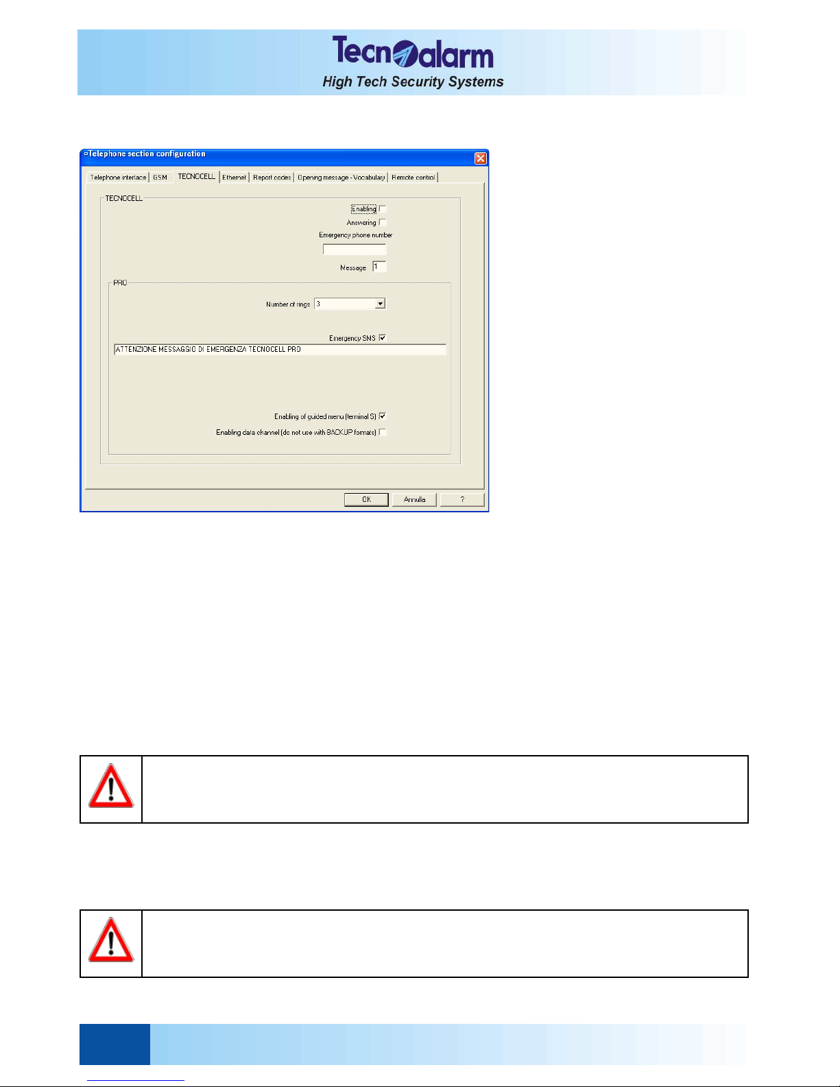
Open the telephone configuration tables and select the Tecnocell window. On the screen is viewed:
TECNOCELL
The Tecnocell configuration table permits enabling and programming of the external GSM telephone communicator.
z Enabling
If enabled, the external GSM telephone communicator signals the alarms to the control panel in case of failure of the
integrated GSM module (primary channel).
z Answering
If enabled, the external GSM telephone communicator answers to the incoming calls sending one of the two
prerecorded voice messages reporting system status (control panel in stand-by or alarm active). The message is
repeated until the communication is closed or for max. 1 minute.
z Emergency phone number
The GSM telephone communicator constantly communicates with the control panel via RS485 serial bus.
If the communication is interrupted (serial line incorrectly connected or missing) for more of 30 seconds, the
communicator makes an emergency call to the programmed emergency phone number (max. 17 digits)
transmitting the prerecorded emergency message.
The item permits programming of the emergency phone number.
z Message
Permits programming of the message to be sent during an emergency call (number 1, 2, 3 or 4)
PRO (only for the TECNOCELL-PRO PL)
z Number of rings
Permits programming of the number of rings to be counted before the telephone GSM communicator answers to the
incoming calls (3 to 15 rings). The communicator is programmed by default to answer after 3 rings.
z Emergency SMS
WARNING
The message function is only available if the GSM telephone communicator is equipped with the
optionnal VOICE module.
WARNING
Enabling of the emergency SMS message, disables the voice emergency call.
Page 49

TP8-96 VIDEO - Installer Manual Programming of telephone section
3-7
The GSM telephone communicator constantly communicates with the control panel via RS485 serial bus.
If the communication is interrupted (serial line incorrectly connected or missing) for more of 30 seconds and the
SMS message function is enabled, the communicator sends an emergency SMS (max. 80 digits) to the
programmed emergency phone number.
The item permits enabling and programming of the emergency SMS.
z Enabling of guided menu (terminal S)
The TP8-96 VIDEO control panel composes the voice messages itself with the help of the onboard vocabulary and
transmits them to the telephone number of the receiver through the S cable (loudspeaker terminal of the CPU board)
to the GSM telephone communicator. The messages of the guided menu are more detailed than those of the GSM
prepayed SIM.
The item permits enabling of the function.
z Enabling data channel (do not use with BACKUP formats)
Never use the GSM telephone communicator as a BACKUP channel (for the 176-188 protocols)
Press:
z OK to confirm and quit
z Abandon to quit without saving
Page 50
Programming of telephone section Installer Manual - TP8-96 VIDEO
3-8
3.1.4 ETHERNET
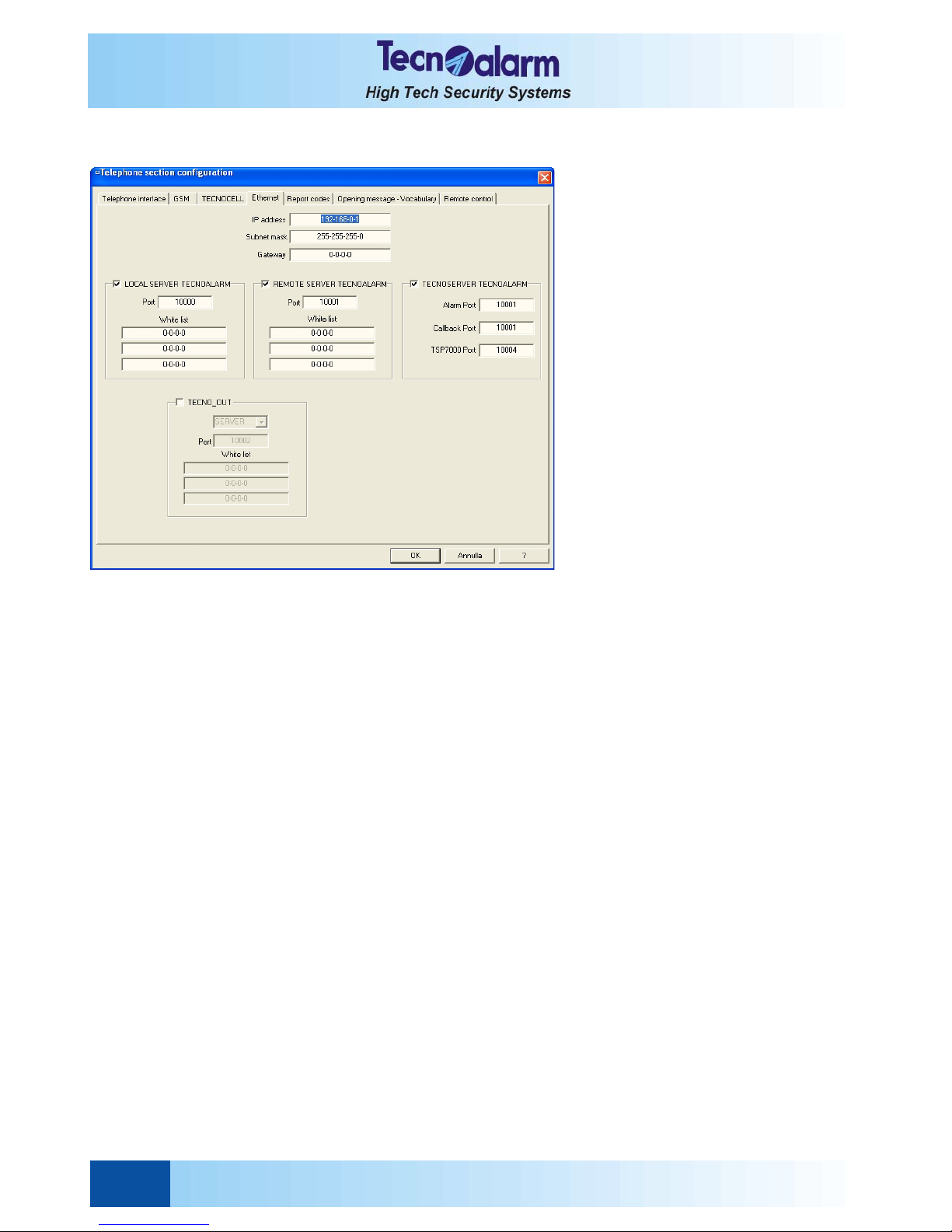
Open the telephone configuration tables and select the Ethernet window. On the screen is viewed:
The Ethernet configuration table permits programming of the following parameters:
z IP address
Permits programming of the control panel IP address. The network address permits identification in an univocal
mode of the control panel connected on the Internet network.
z Subnet mask
Defines the Subnet mask address which is related to the IP address. The two addresses are automatically
compared and the result determines the direction of the datas sent towards the Gateway (WAN) or the local network
(LAN).
z Gateway
It is the IP address of a device which connect the local network (LAN) to the extended one (WAN).
It transmits the communication packs to the external local network, therefore it sends the trafic directed to the
exterior towards the Internet network.
LOCAL SERVER TECNOALARM
Check the item to enable/disable the function.
z Port
TCP/IP communication port of the local Tecnoalarm server channel. Communication port for local programming by
PC. Local connection between PC and control panel.
z White list
List of 3 acceptable communication addresses. If the white list contains addresses, the communication is
accepted from these addresses. If no address has been programmed (i.e. all 3 addresses are 0-0-0-0),
the communication is accepted from any other address.
REMOTE SERVER TECNOALARM
Check the item to enable/disable the function.
z Port
TCP/IP communication port of the remote Tecnoalarm server channel. Communication port for remote programming
by PC. Remote connection between PC and control panel.
z White list
List of 3 acceptable communication addresses. If the white list contains addresses, the communication is
accepted only from these addresses. If no address has been programmed (i.e. all 3 addresses are 0-0-0-0),
the communication is accepted from any other address.
Page 51
TP8-96 VIDEO - Installer Manual Programming of telephone section
3-9
TECNOSERVER TECNOALARM
Check the item to enable/disable the function.
z Alarm Port
TCP/IP communication port through which the control panel transmits the alarms to the monitoring station (remote
connection between monitoring station and control panel).
Modify the number only if the PC port is occupied by another application.
z Callback Port
TCP/IP communication port through which the control panel executes a call-back (remote connection between
monitoring station and control panel).
Modify the number only if the PC port is occupied by another application.
z TSP7000 Port
TCP/IP communication port through which the control panel communicates with the TSP7000 console
(local connection between TSP7000 and control panel).
TECNO_OUT
Protocol for interface software for Building Management systems. The Tecno Out protocol is only disclosed to whom
has signed the Non-disclosure Agreement.
Check the item to enable/disable the function.
It is possible to select the Server or Client functioning mode.
z Port
TCP/IP communication port for the Tecno Out protocol.
z White list
List of 3 acceptable communication addresses. If the white list contains addresses, the communication is
accepted only from these addresses. If no address has been programmed (i.e. all 3 addresses are 0-0-0-0),
the communication is accepted from any other address.
Press:
z OK to confirm and quit
z Abandon to quit without saving
WARNING
The port number must be programmed in the Modem Port page of the monitoring station
configuration.
This function is enabled only to the owners of the Remote IP licence.
WARNING
The port number should not be modified.
Page 52
Programming of telephone section Installer Manual - TP8-96 VIDEO
3-10
3.1.5 REPORT CODES
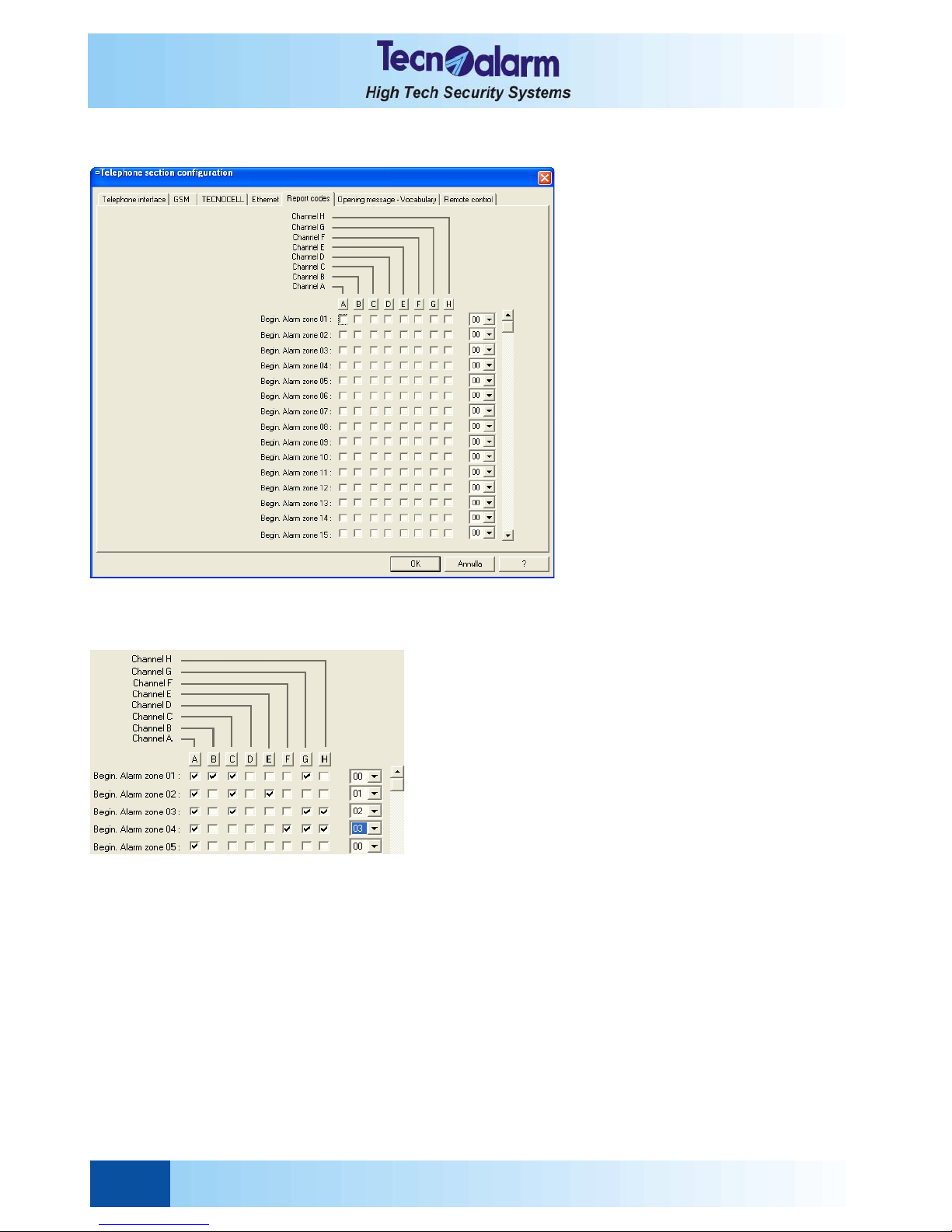
Open the telephone configuration tables and select the Report code window. On the screen is viewed:
The report code configuration table permits both the events-channel association and programming to the report codes.
The report codes identify the alarm type or the event transmitted by a digital call by a non-Tecnoalarm device as a
monitoring station of other costumers.
Each event can be associated to an hexadecimal code (00 to FF) with 2 digits.
EVENT-CHANNEL ASSOCIATION
Enable the association of a specific event to a specific channel
by clicking on the item of the corresponding line to the wished
channel.
Enable the association of all the events to a specific channel by
clicking on the letter corresponding to the wished channel. All
the items of the column are automatically selected.
REPORT CODES DEFINITION
It is possible to define or to modify the report code by clicking
on the lateral scroll bar and by clicking on the wished value
which will be viewed in the report code item.
For select the alarm motives or signaling not viewed, click on the lateral scroll bar until the wished one.
Press:
z OK to confirm and quit
z Abandon to quit without saving
Page 53
TP8-96 VIDEO - Installer Manual Programming of telephone section
3-11
3.1.6 OPENING MESSAGE-VOCABULARY
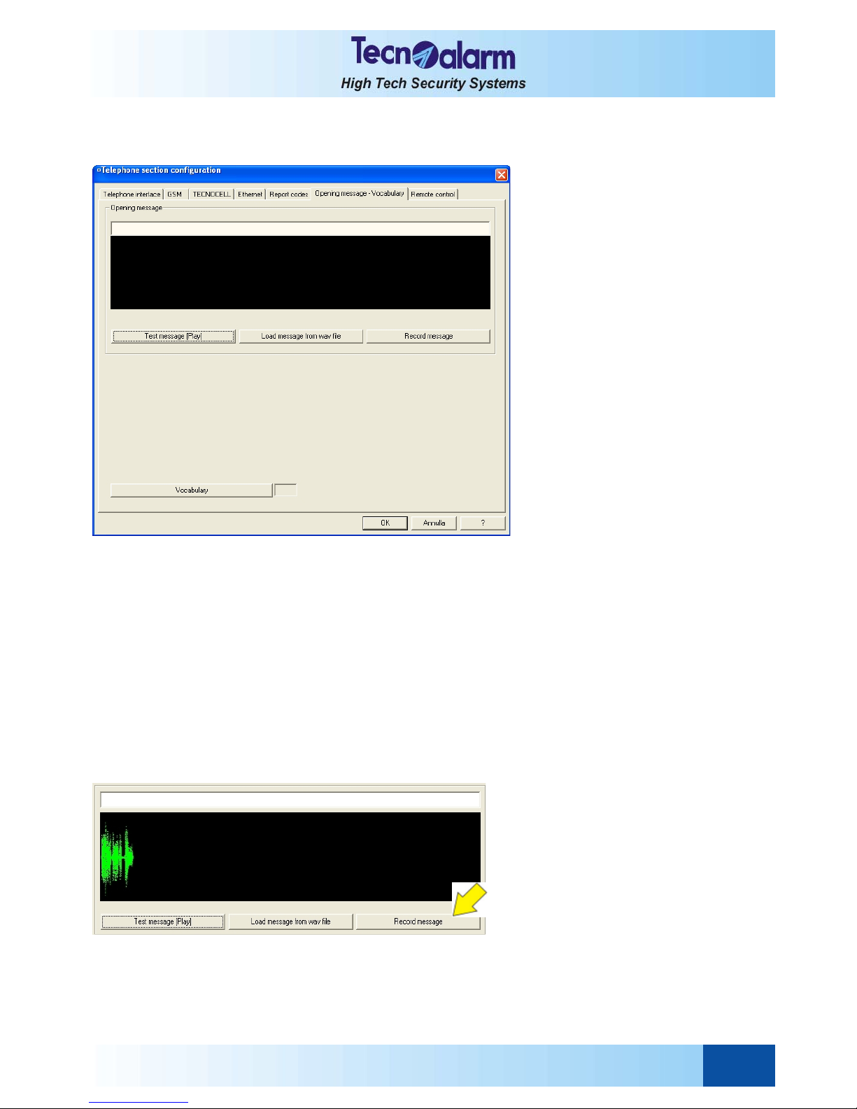
Open the telephone configuration tables and select the Opening message-vocabulary window.
On the screen is viewed:
The opening message is a voice message that is reproduced during every outgoing telephone call. It can be recorded by
the user in different ways: using the Tecnoalarm programming and monitoring software, a special sound manager
resident on your PC, loading from a prerecorded WAV file or by telephone.
The opening message window permits both listening and programming of the message as well as the selection of the
vocabulary for all the system's voice messages:
z Test message (Play)
Permits the reproduction of the programmed message.
z Load message from WAV file
Permits downloading of a WAV file (e.g. from hard disk or floppy) and programming it as the opening message.
z Record message (sound card)
Permits recording of the opening message by using a microphone and the sound card of the PC.
z Vocabulary
Permits the selection of the language of the vocabulary used for the voice messages of the system.
RECORDING OPENING MESSAGE USING TECNOALARM PROGRAMMING AND MONITORING SOFTWARE
Connect a microphone to the sound card of your PC and initiate recording by pressing the button Record message
(sound card)
Speak clearly and loudly. On the screen, the opening message recorded will be displayed as a sound wave.
For interruption, press the button Record message (sound card) again.
The maximum recording time is 16 seconds. Upon expiry of the recording time, recording is automatically stopped.
Page 54
Programming of telephone section Installer Manual - TP8-96 VIDEO
3-12
RECORDING OPENING MESSAGE USING A PC
Connect a microphone to the sound card of your PC and any sound manager whatsoever.
RECORDING OPENING MESSAGE BY TELEPHONE
The message can be recorded during a voice call with the control panel.
The 10 seconds recording time is unchangeable.
Since the recording time is unchangeable, it is recommended to record a message of approximately 10 seconds length
in order to avoid mute periods during the reproduction of the message.
SELECTION OF THE VOCABULARY
Permits the selection of the language of the vocabulary used for the voice messages of the system.
Press the Vocabulary button in the lower part of the window.
The English vocabulary can be found in the following directory C:\Program files\Tecnoalarm\Centro\WAV2\ENG
Select the file Msg_cnf.tcn.
Press:
z OK to confirm and quit
z Abandon to quit without saving
WARNING
z Maximum message length: 16 seconds
z Message format: Windows PCM (.wav)
z Sampling frequency: 8KHz - Mono
z Data format: 8 Bit
WARNING
The selection and modification of the voice messages of the system requires a specific software
utility, TECNOMSG, and is subject to license.
Page 55

TP8-96 VIDEO - Installer Manual Programming of telephone section
3-13
3.1.7 REMOTE CONTROLS
Open the telephone configuration tables and select the Remote control window. On the screen is viewed:
ASSOCIATION-COMPOSITION OF THE VOICE MESSAGE
The control panel can manage max. 8 remote controls.
It is possible to associate an individual description to each remote control that will replace the zone number and identify
the program in every process. The remote control description will be viewed on the display and announced by the
speaker of the console.
A The voice message can be composed of max. 4 words selectable among those included in the vocabulary.
4 items are viewed, one for each word.
Click on the arrow of each item to scroll the vocabulary and select the word.
B At the end, click on the validation arrow B to memorize and play the message.
The words are automatically copied into the description line. It is possible to program the description manually
writing directly it in the description line.
Remember that the display of the console views descriptions of maximum 16 characters. All further
characters will be cut off.
ACTIVATION TIME
Permits programming of the activation time (in minutes and seconds) of each remote control.
An activation of max. 59 minutes and 59 seconds can be programmed.
z Activation of the remote controls can be pulsed, i.e. upon reception of the commutation command the remote control
is activated. It is activated upon expiry of the programmed activation time:
<commutation><activation time><commutation>
z The remote controls behave has a toggle if no activaion time has been programmed:
<commutation><commutation>
Repeat the operations for every remote control to be configured (max. 8).
Press:
z OK to confirm and quit
z Abandon to quit without saving
A
B
Page 56
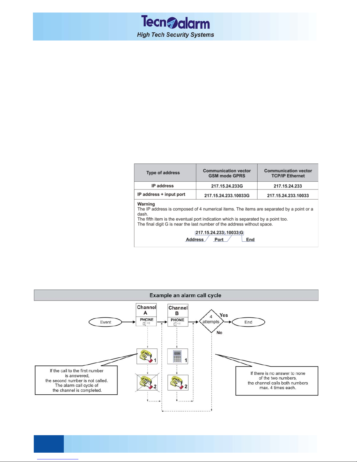
Programming of telephone section Installer Manual - TP8-96 VIDEO
3-14
3.2 EXPLANATORY NOTES
3.2.1 TELEPHONE NUMBERS
Telephone numbers format
The telephone numbers items can contain max. 24 digits, inside of which it is possible to enter the telephone numbers
of a fixed network (PSTN) or of the mobile phone (GSM) or the network IP addresses.
z Telephone number Format of a telephone number.
No particular rule for the telephone number formation.
z IP address (ethernet network) Format of an IP address.
The IP address can be formed by 4 or 5 numerical items.
The last item can be finished with the letter G.
• The first 4 item indicate the IP address of the Tecnoalarm monitoring
station with which communicate.
• The fifth item indicates the access port (it is not compulsory to fill in this
item).
• The last letter G indicates to the control panel the GRPS communication
mode
The control panel can count the IP addresses using either the internal switch
connected to the Ethernet network or the GSM module in GPRS mode.
Alarm call cycle
The principal number 1 (tel 1) is called first. In case there is no answer or the line is busy, the reserve number (tel 2) is
called. If there is no answer to both numbers, the system passes to the next channel associated to the same event.
For each channel, 4 attempts are executed with either number.
Page 57
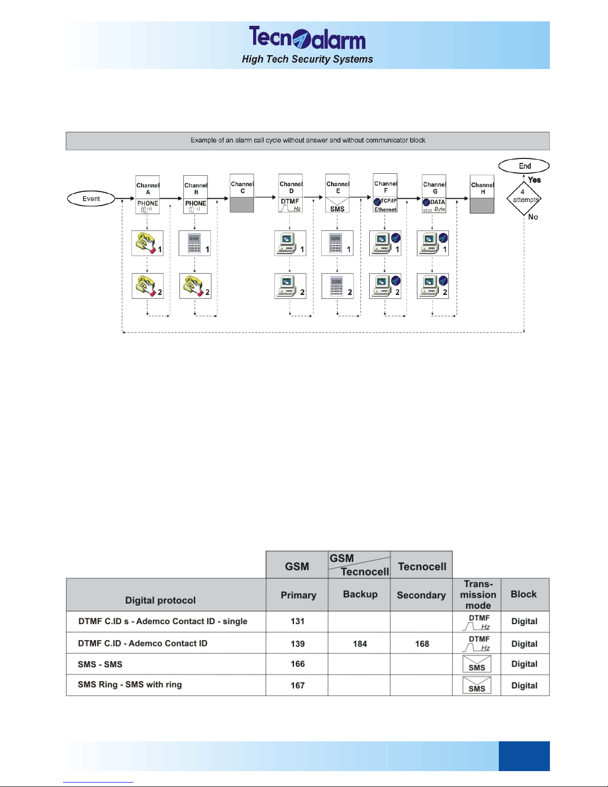
TP8-96 VIDEO - Installer Manual Programming of telephone section
3-15
Priority
All the channels have the same priority. Each alarm call cycle starts with channel A. The only exception is the hold-up
alarm. If an alarm is being transmitted, the active alarm call cycle is interrupted and the alarm call cycle for the hold-up
alarm is started immediatly. At the end of the alarm call cycle, the previous cycle is restarted. Henceforward, the
normal order continues. The call-back has no priority and can be interrupted by any alarm call cycle.
3.2.2 PROTOCOLS
The communication protocols of the control panel are divided into vocal, digital and Tecnoalarm digital protocols.
The telephone channels of the control panel support the PSTN, GSM and Ethernet vectors. In addition to the
integrated GSM interface, the control panel manages the GSM telephone communicator connected via serial bus
(TECNOCELL).
Each protocol has a number code.
The protocols are classified as:
z Primary transmitted by the GSM module of the control panel
z Secondary transmitted by the external GSM telephone communicator
z Backup transmitted by the GSM module of the control panel
If the integrated GSM module fails, the alarm is transmitted by the external GSM telephone
communicator.
z Ethernet transmitted by the Ethernet switch of the control panel
In the tables, the protocols are divided by categories (digital, Tecnoalarm, vocal) and, for each of them the name, the
number code and the classification (primary, backup, secondary, Ethernet) as well as the transmission mode are
indicated.
Page 58
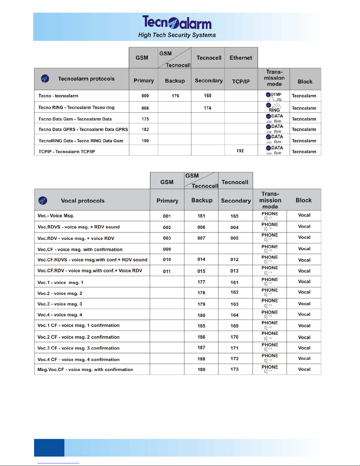
Programming of telephone section Installer Manual - TP8-96 VIDEO
3-16
Page 59
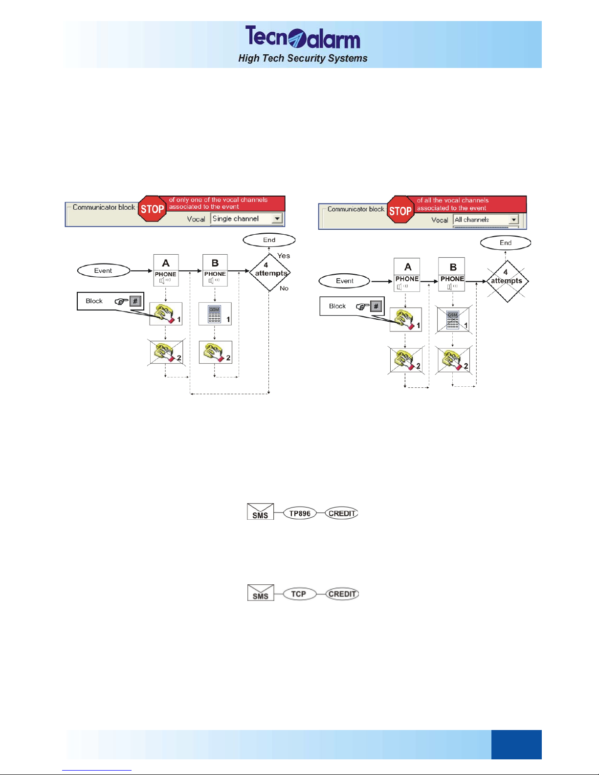
TP8-96 VIDEO - Installer Manual Programming of telephone section
3-17
3.2.3 COMMUNICATOR BLOCK
The alarm call cycle can be interrupted. The recipients of the calls, users or automatic alarm reception devices, can
block the channel with specific commands.
The communicator block distinguishes: vocals, digitals and Tecnoalarm protocols. It is selective for each category of
protocols. It can act on the single or on all of the channels associated to the event.
Communicator block of the digital and Tecnoalarm channels
After reception of the event, the monitoring station automatically sends the communicator block command to the control
panel.
Communicator block of the vocal channels
During the conversation, after listening to the alarm message, the user can block the channel by presing the * or #
key on the phone.
3.2.4 AIRTIME REQUEST
If the GSM telephone communicators use prepaid SIM cards, it is necessary to verify the remaining credit once in a
while.
GSM module
Program the parameters for the airtime request according to the service provider used. The airtime request SMS can be
sent at any time.
Tecnocell
The external GSM telephone communicator does not need any programming. The airtime request SMS can be sent at
any time.
The message is only accepted and the request is handled if the message is written in capital letters.
Page 60
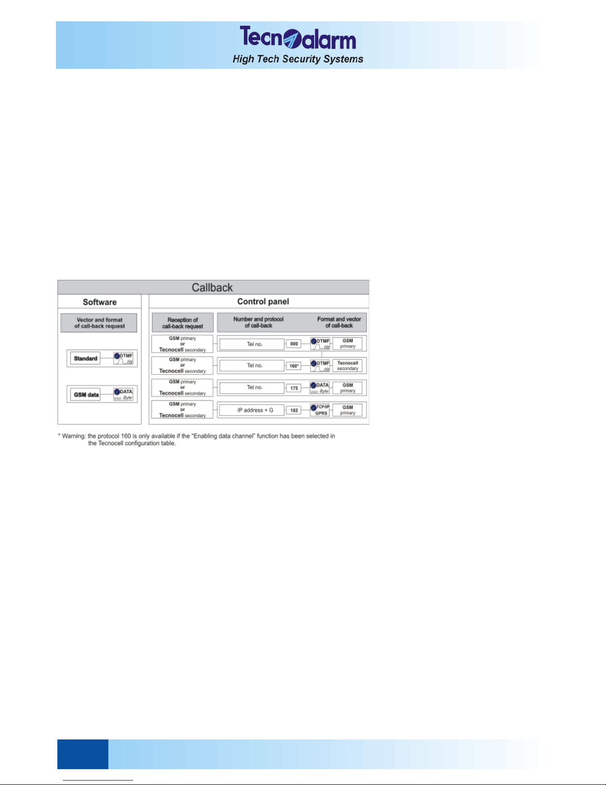
Programming of telephone section Installer Manual - TP8-96 VIDEO
3-18
3.2.5 CALL-BACK
Call-back mode
z Standard call-back
The monitoring station calls the control panel which recognizes that the call is arrived from a Tecnoalarm monitoring
station and accepts the communication. During the communication the ID code and the control panel model are
controled. The control panel closes the communication and calls the monitoring station according to the
programmed parameters.
Example:
1 Call-back request by centro The monitoring station calls the control panel on the PSTN line using a DTMF
format.
2 Call-back by TP8-96 VIDEO The control panel, through the GSM interface, receives the request of a
call-back from the monitoring station.
The control panel exchanges the ID data (call-back no. and format) with the
monitoring station, then closes the communication.
call back format 000 Tecno Standard
the call-back number/IP address
Then it calls the monitoring station back.
3 Call-back reception by centro The monitoring station receives the call on the PSTN line in a DTMF
format (Tecno Standard).
z Call-back redirection
This function is only available if the Disable redirection option is not enabled.
In this case, the device is requested indicates to call a different telephone number than the call-back numbers
programmed. The control panel calls this number maintaining the programmed communication format (see above
scheme).
Page 61
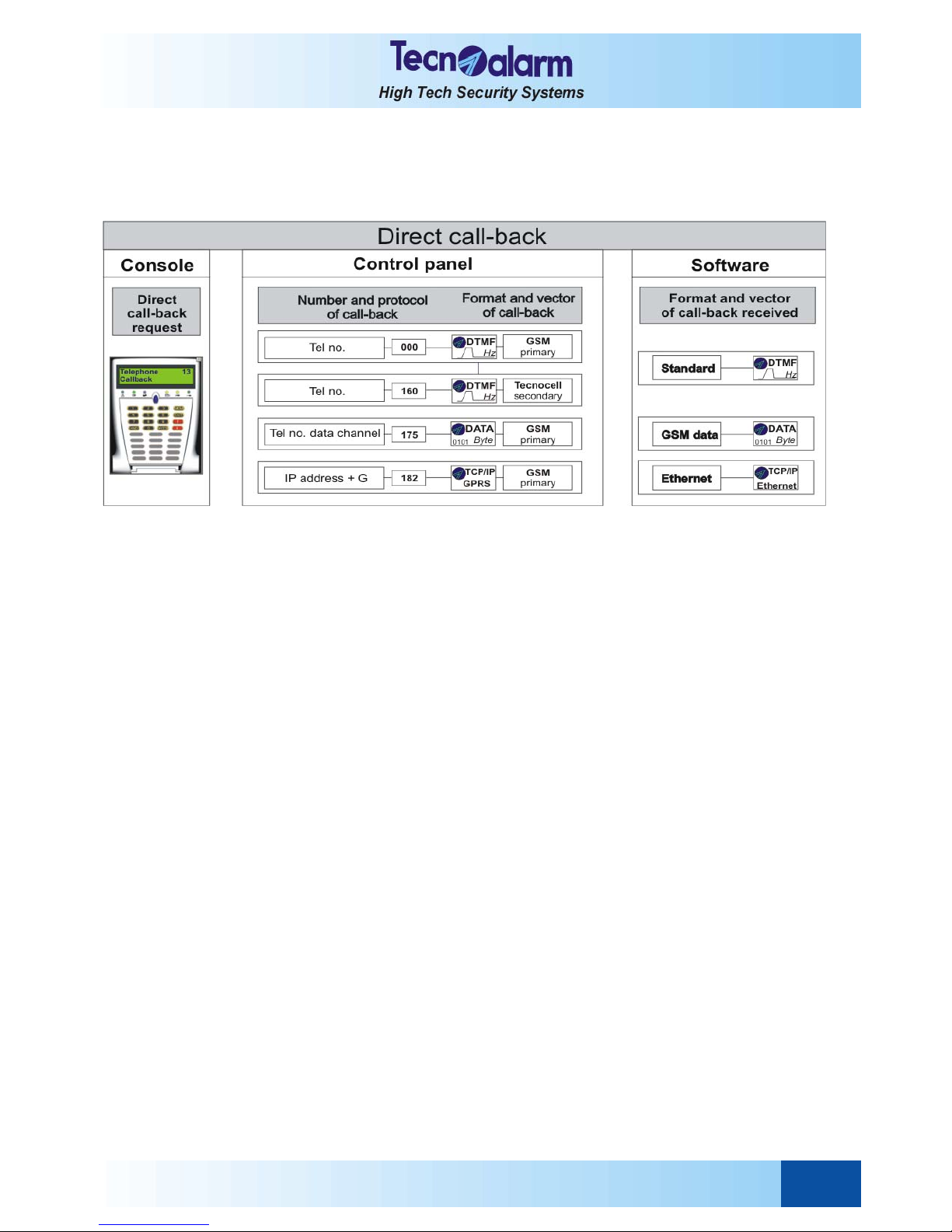
TP8-96 VIDEO - Installer Manual Programming of telephone section
3-19
z Direct call-back
It is possible to initiate a call-back locally through the LCD300/S console. Select the menus Telephone, then Callback from the installer menu.
The control panel immediatly calls the monitoring station according to the programmed parameters.
Page 62
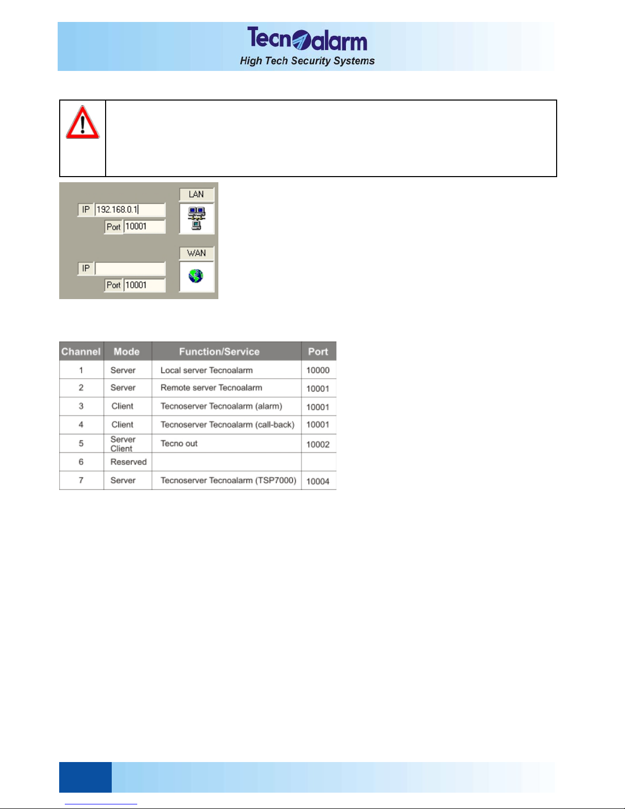
Programming of telephone section Installer Manual - TP8-96 VIDEO
3-20
3.2.6 ETHERNET
The table summarizes the functioning mode, the function and the communication port of each channel:
Vocabulary
z Client Component which benefits from services/resources provided by a Server via the network.
z Server Computer which provides services/resources to a client via the network.
z LA N Local Area Network, i.e. a local network which covers a limitated geographical area such as a building.
z WAN Wide Area Network, i.e. a network covering a vast geographical area.
WARNING
The following programming must be transcribed into the user archive:
z LAN IP address of the control panel and the communication port of the Local Server
Tecnoalarm.
z WAN Communication port of the Remote Server Tecnoalarm.
The IP address should only be filled i a static IP address is available, otherwise leave the
item blank.
Page 63
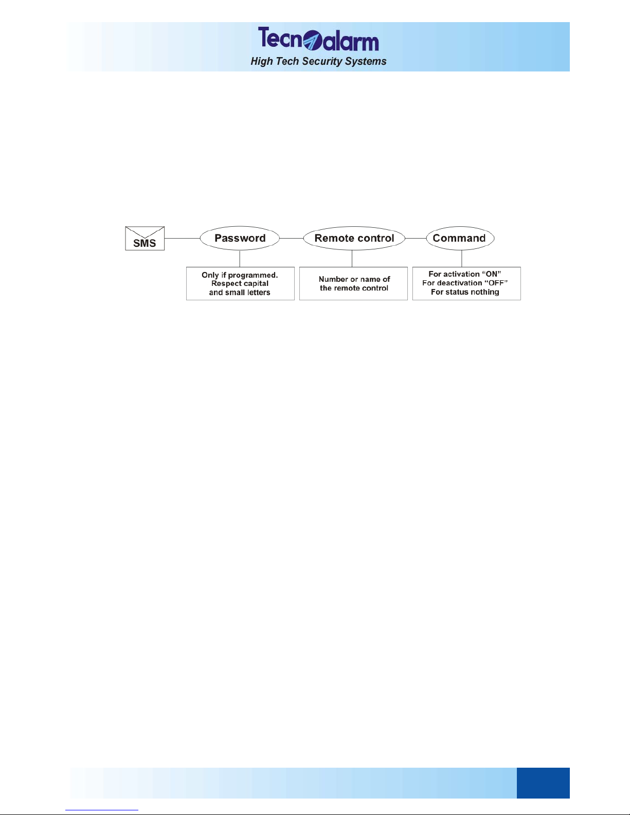
TP8-96 VIDEO - Installer Manual Programming of telephone section
3-21
3.2.7 REMOTE CONTROL MANAGEMENT BY SMS
The remote controls can be managed by SMS.
The remote control management by SMS is programmed in the GSM configuration table.
z COMMANDS-SMS enabling Enable the function
z Password The password is optional. If it is programmed, it must be included in every
SMS. It can be composed of 1 to 8 alphanumerical characters (match
case relevant)
z White list The list contains the telephone numbers enabled to manage the remote
controls by SMS.
If no number has been programmed, SMS commands are accepted from
any telephone number.
Composition of the message
The message is composed of 2 to 3 elements: password (if programmed), remote control and command.
z Blank spaces Each of the three elements (words) provides precise information to the
control panel. This is why they must be clearly distinguished by one blank
space each.
z Password (if programmed) The password must exactly correspond to the programmed one. Pay
attention to the capital and small letters.
The first letter is always an upper-case letter because the password is the
first word of the message.
z Remote control The remote control can be written as a number or name.
The max. length of the name is 16 digits (match case irrelevant)
z Command • ON for activation of the remote control.
• OFF for deactivation of the remote control.
• Nothing for status polling
The ON and OFF commands can be written both with capital and lower
case letters.
Answer of the control panel
When the control panel receives the SMS message, it checks the password and telephone number as well as the
remote control and, if all three are correct, it returns an SMS message composed of the heading of the SMS message
(as it has been programmed in the GSM configuration table), the name or the remote control number as well as its
status.
If either the password or the telephone number are incorrect, there will be no answer.
If the remote control number or its name are incorrect, the control panel returns an error message.
Page 64

Programming of telephone section Installer Manual - TP8-96 VIDEO
3-22
Page 65
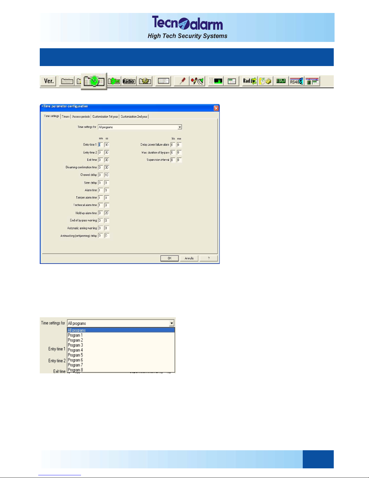
TP8-96 VIDEO - Installer Manual Programming of time parameters
4-1
4. PROGRAMMIING OF TIME PARAMETERS
Permits programming of the time parameters of the control panel. Click on the above icone. On the screen is viewed:
The tables of the configuration time permit to program the following parameters:
z Time parameters
z Timers
z Access periods
z Customization of the calendar (biennal)
4.1 TIME SETTINGS
SELECTION OF THE PROGRAM
To program the time parameters of all the programs, select
all programs.
Page 66

Programming of time parameters Installer Manual - TP8-96 VIDEO
4-2
To program the time parameters, click on the name and enter the required value.
z Entry time 1 and 2 (mm:ss)
The entry time is considered by delayed zones only. It is the interval between the detection of an alarm and the
release of the alarm (0...59m:59s). It is possible to program two different entry times.
z Exit time (mm:ss)
The exit time is considered by delayed zones only. It is the interval between arming and enabling of the zones for
the detection of alarms (0...59m:59s).
z Retard confirmation MHS (mm:ss)
Disarming confirmation time (mm:ss)
This parameter indicates the delay for confirmation of disarming and stopping of the hold-up alarm (see programming
of the keys). If no valid code is entered within the programmed disarming confirmation time, a silent hold-up alarm is
released. If the delay is 0, the program is disarmed immediately without confirmation by any valid code enabled for
the program in question.
If programmed accordingly, even quick disarming is accepted (*).
z Channel delay (mm:ss)
Permits programming of the interval between the detection of an alarm and the activation of the channels.
z Siren delay (mm:ss)
Permits programming of the interval between the detection of an alarm and the activation of the sirens. If the
programmed delay excedes siren cut-off, the sirens are not activated, otherwise it is deduced from siren cut-off, e.g.
if siren cut-off is 2m and siren delay is 1m:30s, the sirens will be active for 30s.
z Alarm time (mm:ss)
This parameter indicates the duration of signaling for zone alarm (indoor-outdoor-radio sirens/supervisory boards).
z Tamper alarm time (mm:ss)
This parameter indicates the duration of signaling for tamper alarm (indoor-outdoor-radio sirens/supervisory boards).
z Technical alarm time (mm:ss)
This parameter indicates the duration of signaling for technical alarm (indoor-outdoor-radio sirens/supervisory
boards).
z Hold-up alarm time (mm:ss)
This parameter indicates the duration of signaling for hold-up alarm (flashing lights/supervisory boards).
z End of by-pass warning (mm:ss)
Permits programming of the duration of end of by-pass warning (buzzer on the consoles) before the by-pass is
deactivated.
z Automatic arming warning (mm:ss)
Permits programming of the duration of automatic arming warning (buzzer on the consoles) before the programs in
question are armed (see programming of the timers)
z Antimasking (antijamming) delay (mm:ss)
This parameter indicates the delay of release of antimasking alarm, i.e. the period of time during which the jamming
signal must persist before a masking alarm is released.
z Delay power failure alarm (hh:mm)
This parameter indicates the delay of release of power failure alarm. The release of power failure alarm can be
delayed in order to avoid false alarms due voltage drops or mains disconection for maintenance etc.
z Max. duration of by-pass (hh:mm)
Permits programming of the time limit for by-pass.
z Supervision interval (hh:mm)
This parameter indicates the delay of release of supervision alarm, i.e. the period of time during which the
communication with the wireless devices must be missing before a supervision alarm is released.
Press:
z OK to confirm and quit
z Abandon to quit without saving
Page 67
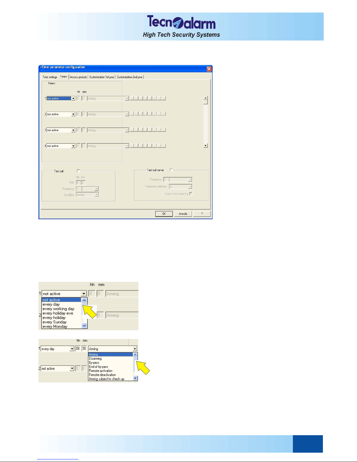
TP8-96 VIDEO - Installer Manual Programming of time parameters
4-3
4.2 TIMERS
Open the time configuration tables and select Timer window. On the screen is viewed:
The timer configuration table permits:
z Programming of the 16 timers
z Programmation of the test call
z Programmation of the test call server
PROGRAMMING OF THE TIMERS
The following parameters can be set for every timer:
z Frequency of activation
z Hour of activation
z Associated function
z Associated programs (1 to 8) or remote controls (1 to 8)
Frequency of activation
Select the timer to be configured by clicking on the first item from the
left and scroll down the list to select the frequency:
z Not active z Every day
z Every working day z Every holiday-eve
z Every holiday z Every sunday
... z Every saturday
Hour of activation
Select the items hh and mm and enter the hour of activation
requested.
Associated function
Select the function item and scroll down the list to select the function
the timer has to execute:
z arming
z disarming
z by-pass
z activation of remote control
z deactivation of remote control
z Qualified arming (avoid arming in the presence of low battery,
power failure, tamper, supervision, fault and antimasking alarm).
Page 68
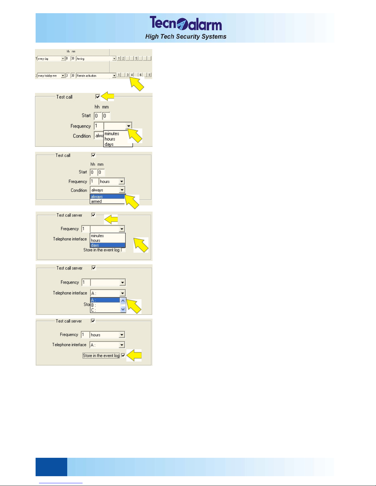
Programming of time parameters Installer Manual - TP8-96 VIDEO
4-4
Associated programs or remote controls
To associate the timers to the programs or remote controls
press the key below the number key. It is possible to associate
a total of 8 programs and 8 remote controls to every timer.
Repeat the procedure for every timer to be configured.
TEST CALL CONFIGURATION
Permits the remote functioning check of the control panel. It
consists in one or several telephone calls made by the channels
the test call is associated to (see report codes) to the
programmed telephone numbers
The calls are made at a determined time with a programmed
frequency.
To enable the test call check the corresponding item.
The following parameters can be set for every timer:
z Hour of activation
z Frequency of activation
z Condition
Starting hour of the test call cycle
To program the starting hour of the test call cycle, select the
item next to Start and enter the time (hh:mm).
Frequency
To program the test call frequency select the item Frequency
and enter a value from 1 to 255.
Then select the unit of the intervall between a test call and the
next (i.e. minutes, hours or days).
Condition
The test call cycle can be bound to system status, i.e. it can
always be executed or only if the control panel is armed.
Select the item Condition and subsequently the condition of
execution requested (i.e. always or armed).
TEST CALL SERVER CONFIGURATION
Permits the automatic check-up of the network connection
between the control panel and the monitoring station. The
connection is made via Ethernet using the TCP/IP protocol.
Frequency
To program the test call server frequency select the item
Frequency and enter a value from 1 to 255.
Then select the unit of the intervall between a test call and the
next (i.e. minutes, hours or days).
Telephone interface
Select the channel (A...H). Ensure that the channel in question
is prgrammed with the TCP/IP Tecnoalarm data protocol
(number code 192).
Store in the event log
Permits to enable/disable the test call event in the archive of the
control panel
Check the item to enable the function.
See § 4.5 for explanatory notes.
Press:
z OK to confirm and quit
z Abandon to quit without saving
Page 69
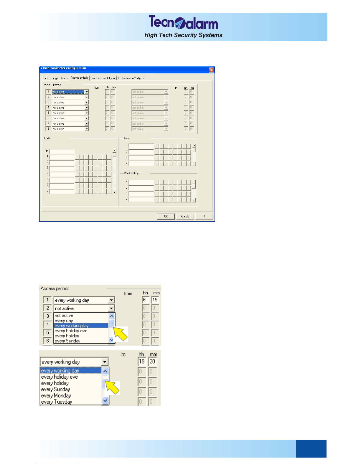
TP8-96 VIDEO - Installer Manual Programming of time parameters
4-5
4.3 ACCESS PERIODS
Open the time configuration tables and select Access period window. On the screen is viewed:
The access period configuration tables permit:
z Configuration of 8 access periods
z Association to the codes (1 to 200)
z Association to the keys (1 to 64)
z Association to the wireless keys (1 to 100)
CONFIGURATION OF THE ACCESS PERIODS
The access periods limit acceptance of the codes/keys to
precise periods of time.
The control panel provides max. 8 access periods (even on
different days).
For every access period the following parameters can be
programmed:
z Frequency of activation and activation time (from)
z Frequency of deactivation and deactivation time (to)
Frequency of activation
Select the relevant item and scroll down the list selecting the
frequency requested:
z Not active z Every day
z Every working day z Every holiday-eve
z Every holiday z Every sunday
... z Every saturday
Activation time
To program the activation time of the access period, select the
item next to the frequency and enter the time (hh:mm).
Frequency of deactivation
Select the relevant item and scroll down the list selecting the
frequency requested:
z Not active z Every day
z Every working day z Every holiday-eve
z Every holiday z Every sunday
... z Every saturday
Deactivation time
To program the deactivation time of the access period, select
the item next to the frequency and enter the time (hh:mm).
Page 70
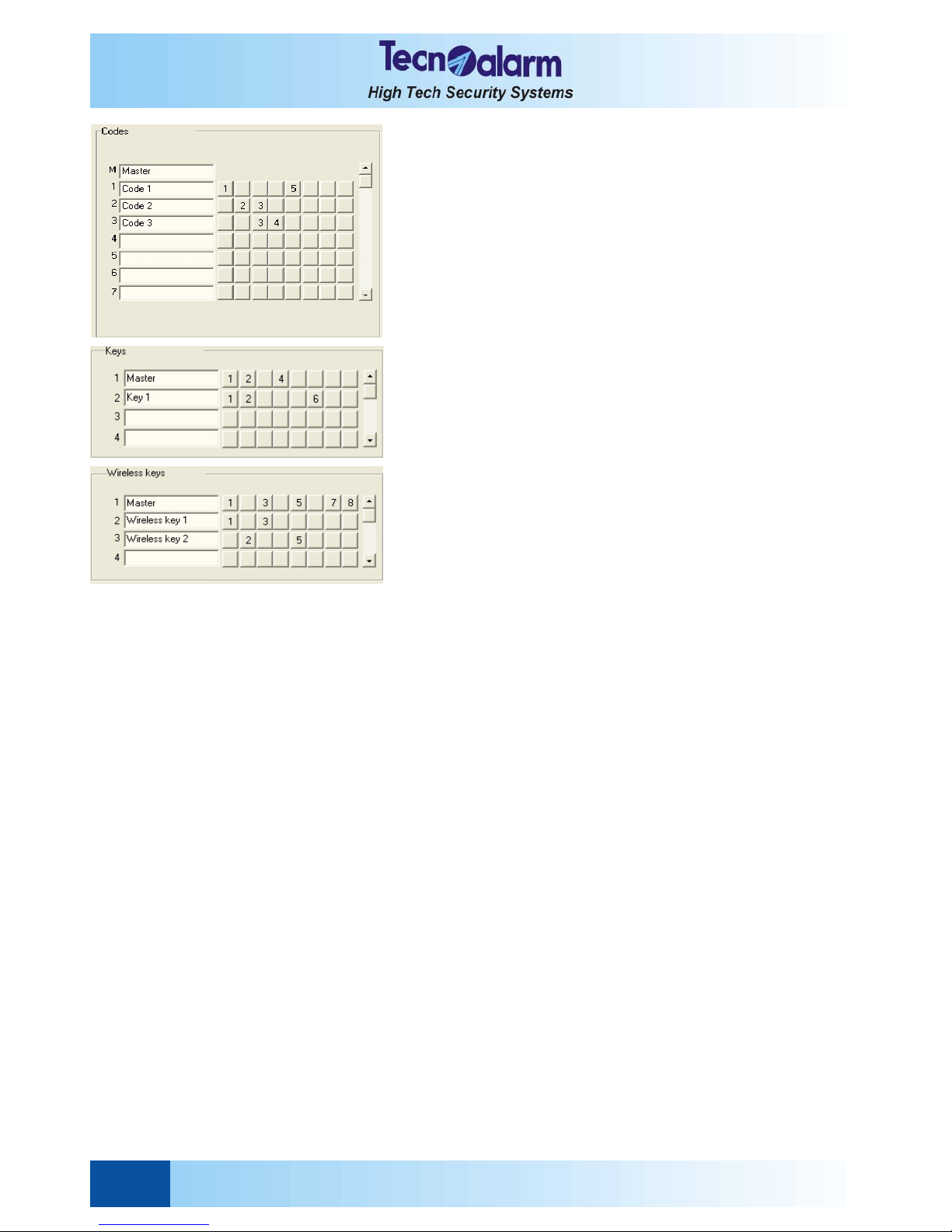
Programming of time parameters Installer Manual - TP8-96 VIDEO
4-6
ASSOCIATION OF THE ACCESS PERIODS TO THE CODES
It is possible to associate the access periods to the user
codes.
In this way, the owner of every code (i.e. cleaning staff) can
initiate the associated functions only during the period of time it
is enabled for.
To associate the access periods to the codes press the relevant
items next to the code name. The number of the access period
will be viewed as a confirmation of the association.
ASSOCIATION OF THE ACCESS PERIODS TO THE KEYS
It is possible to associate the access periods to the keys.
In this way, the owner of every key (i.e. employees) can initiate
the associated functions only during the period of time it is
enabled for.
To associate the access periods to the keys press the relevant
items next to the key name. The number of the access period
will be viewed as a confirmation of the association.
ASSOCIATION OF THE ACCESS PERIODS TO THE
WIRELESS KEYS
It is possible to associate the access periods to the wireless
keys.
In this way, the owner of every wireless key (i.e. employees)
can initiate the associated functions only during the period of
time it is enabled for.
See § 4.5 for explanatory notes.
Press:
z OK to confirm and quit
z Abandon to quit without saving
Page 71
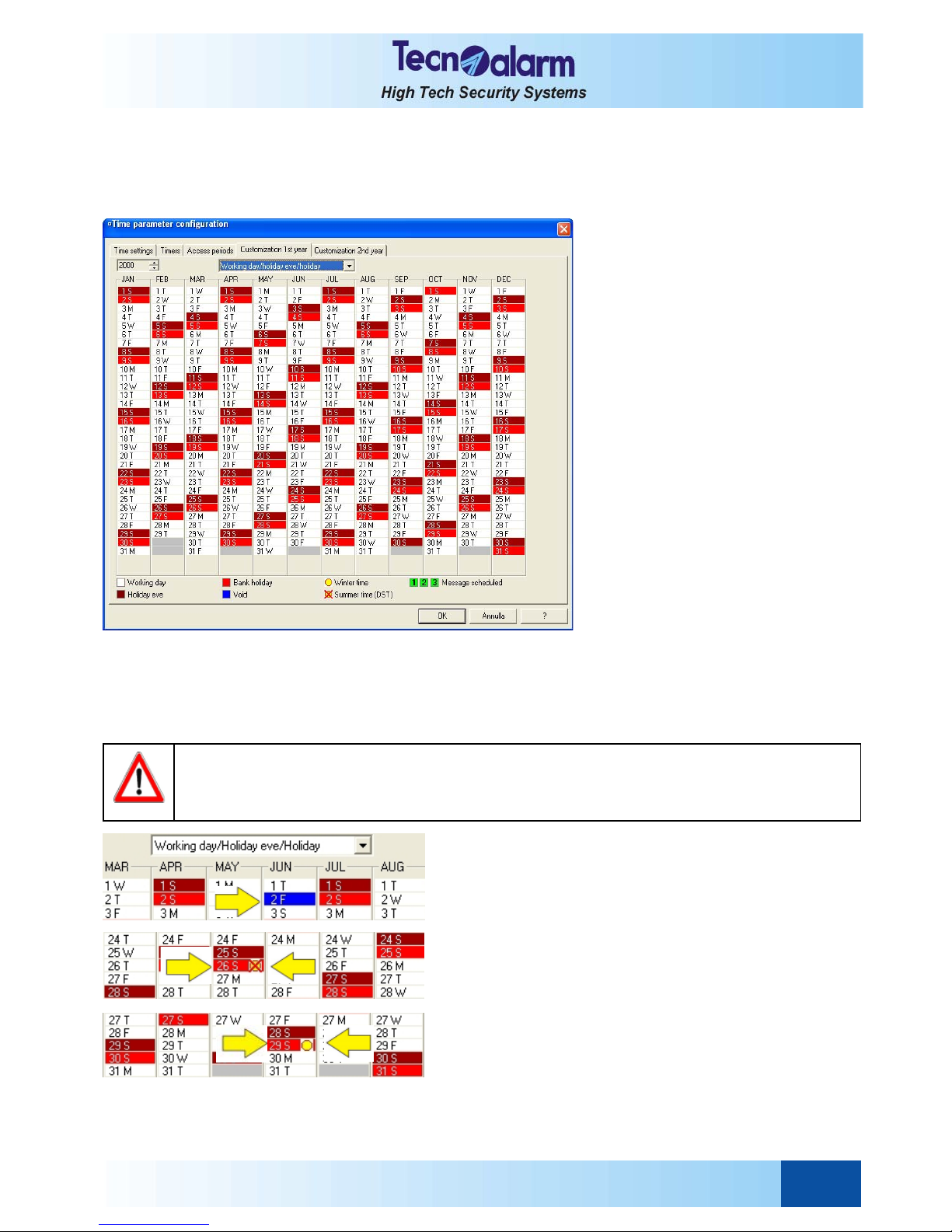
TP8-96 VIDEO - Installer Manual Programming of time parameters
4-7
4.4 CUSTOMIZATION OF THE CALENDAR
The control panel provides a customizable biennial calendar for all automized functions that are controlled by the clock
of the control panel. The calendar permits customization of the bank holidays, definition of the holiday eves and the
days of summer-winter time change.
Open the time configuration tables and select Customization 1st year window. On the screen is viewed:
THE ATTRIBUTES OF THE DAYS
Every kind of day is distinguished by a different colour:
z White working day
z Dark red holiday eve
z Light red holiday
z Blue void day (none of the above attributes is valid)
PROGRAMMING OF THE ATTRIBUTES
Prior to programming of the attribute of a day ensure that in the
box above the calendar is viewed Working day/Holiday eve/
Holiday, then click on the day several times until it assumes
the colour of the attribute requested.
PROGRAMMING OF THE WINTER-SUMMER TIME CHANGE
To program the beginning and the end of summer time(daylight
saving) click on the item above the calendar and select
Summer time (DST), then click once on the day of beginning
of summer time. A crossed sun will be shown next to the date.
Subsequently select Winter time and click once on the day of
end of summer time. A sun will be shown next to the date.
WARNING
A void day is neither a working day, nor a holiday or a holiday eve. The attribute "void" has been
implemented in order to permit una tantum modifying of the settings of a timer that has been
programmed for operations on days with other attributes (i.e. working day/holiday eve/holiday).
Page 72
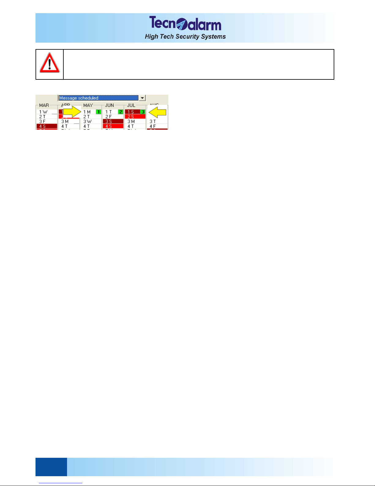
Programming of time parameters Installer Manual - TP8-96 VIDEO
4-8
PROGRAMMING OF THE VIEWING OF THE SCHEDULED
MESSAGE DATE
The control panel permits programming of 3 differents
messages.
To program the beginning of the date of the message, click
on the item above the calendar end select Message
scheduled, then click on the day selected several times
until the number (1, 2 or 3) in green will be shown next to the
date (e.g. on May the 1st the message scheduled with the
number 1 will be viewed on the console).
Clicking the 4th time, the selected message will be remove.
Repeat the procedure for the second year (Customization
2nd year).
Press:
z OK to confirm and quit
z Abandon to quit without saving
WARNING
The change from winter to summer time and back happens automatically and always in the night at
respectively 2 and 3 o'clock.
Page 73
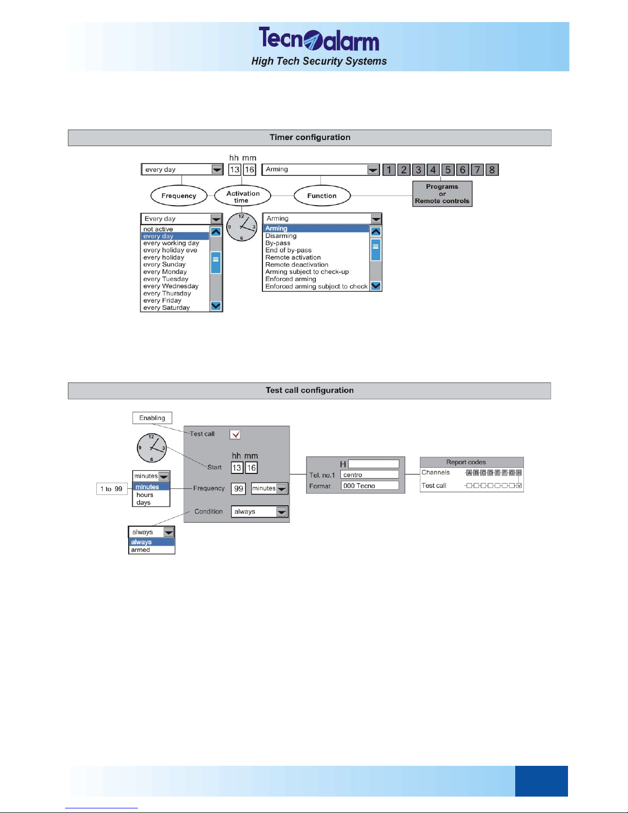
TP8-96 VIDEO - Installer Manual Programming of time parameters
4-9
4.5 EXPLANATORY NOTES
The following schemes evidence the steps of configuration of the timers, test call, test call server and access periods.
TIMERS
TEST CALL
Page 74

Programming of time parameters Installer Manual - TP8-96 VIDEO
4-10
TEST CALL SERVER
ACCESS PERIODS
Page 75
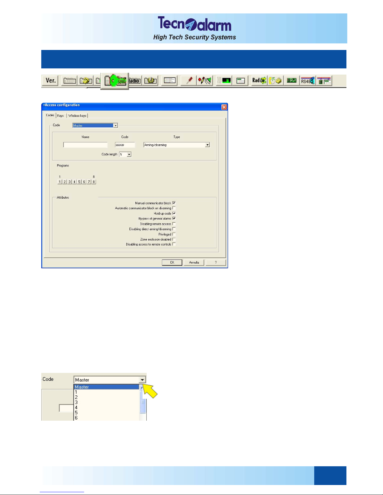
TP8-96 VIDEO - Installer Manual Programming of access codes and keys
5-1
5. PROGRAMMING OF ACCESS CODES AND KEYS
Permits programming of the control panel access parameters. Click on the above icon. On the screen is viewed:
The tables of the access configuration permit:
z Programming of the codes
z Programmation of the keys
z Programmation of the wireless keys
5.1 PROGRAMMING OF THE CODES
The code configuration table permits:
z Programming of the code name
z Programming of the code value
z Association of the functions
z Programming of the length of all the system's codes
z Association of the programs
z Programming of the attributes of the codes
SELECTION OF THE CODE
Select the item next to Code and scroll down the list then, click
on the name of the code to be programmed.
Page 76
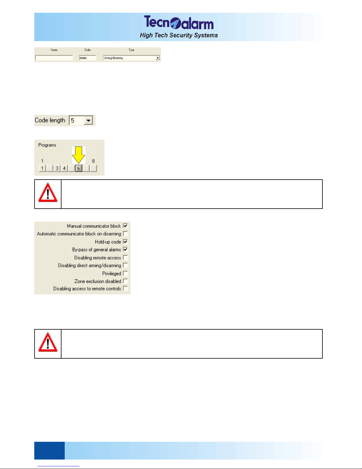
Programming of access codes and keys Installer Manual - TP8-96 VIDEO
5-2
PROGRAMMING OF THE CODE
For every code the following parameters can be programmed:
z Name or description (max. 16 caracters), e.g. the name of
the owner of the system
z Code
The code value is the numerical value associated to the
code and to be entered for initiation of the function
programmed (e.g. 23668).
The maximum length of the code depends on what has
been programmed in the item Code length.
z Type, i.e. the function that is initiated upon entering of the
code (arming/disarming or by-pass)
z Code length
The code length is relevant for all the codes of the system.
The control panel accepts 4 to 6-digits codes. The default
code length is 5 digits.
CODE-PROGRAMS ASSOCIATION
The code will only be enabled to act on (arm/disarm or partset)
the associated programs (1 to 8).
To associate a program to the code, click on the corresponding
item. The program number will be shown as a confirmation of
the association.
PROGRAMMING OF THE ATTRIBUTES
To associate the attributes to the code, check the relevant item.
z Manual communicator block
If checked, upon disarming of the system (by entering the
user code) the active telephone channels (and those
queued up) can be blocked by entering the user code
again followed by the EXIT key.
z Automatic communicator block on disarming
If checked, upon disarming of the system (by entering the
user code) the active telephone channels (and those
queued up) are blocked automatically.
z Hold-up code
Activates the hold-up function on the code. Under duress
the user can so apparently disarm the system and
simultaneously release a silent alarm by entering a slightly
different code. The hold-up code differs from the user code
only in the last figure that is decreased by one unit, e.g. the
owner of the master code (default code 12345) will release
a hold-up alarm by entering:
+ 12344
z By-pass general alarms
If checked, the user will be entitled to arm the system even
in presence of a general alarm (i.e. tamper, low battery,
power failure, supervision, trouble modules)
z Disabling of remote access
If checked, the user will not be entitled to arm or disarm
the associated programs at distance by telephone.
z Disabling of direct arming/disarming
If checked, the user will not be entitled to arm all the
associated programs directly by pressing the hash key (#)
but will have to arm them one after the other.
WARNING
The master code is generally reserved to the owner of the system. It is always enabled to act on all
the system's programs.
WARNING
If the code ends in 0, the hold-up code ends in 9, e.g. 12340 becomes 12349.
Page 77

TP8-96 VIDEO - Installer Manual Programming of access codes and keys
5-3
z Privileged
If checked, the code beside the normal functions is enabled for viewing of the general alarm log and the event
log of the associated programs. In addition, the code will give access to part of the programming menu.
z Exclusion disabled
If checked, the user will not be entitled to arm the control panel excluding some of the zones (both voluntary and
automatic zone exclusion are disabled). The control panel will be armed in any case, and if there are open zones,
the alarm will be released.
z Disabling access to remote controls
If checked, the user will not be entitled to arm or disarm the associated programs at distance by remote controls.
Repeat the procedure for all the user codes (1 to 200).
See § 5.4 for explanatory notes.
Press:
z OK to confirm and quit
z Abandon to quit without saving
Page 78
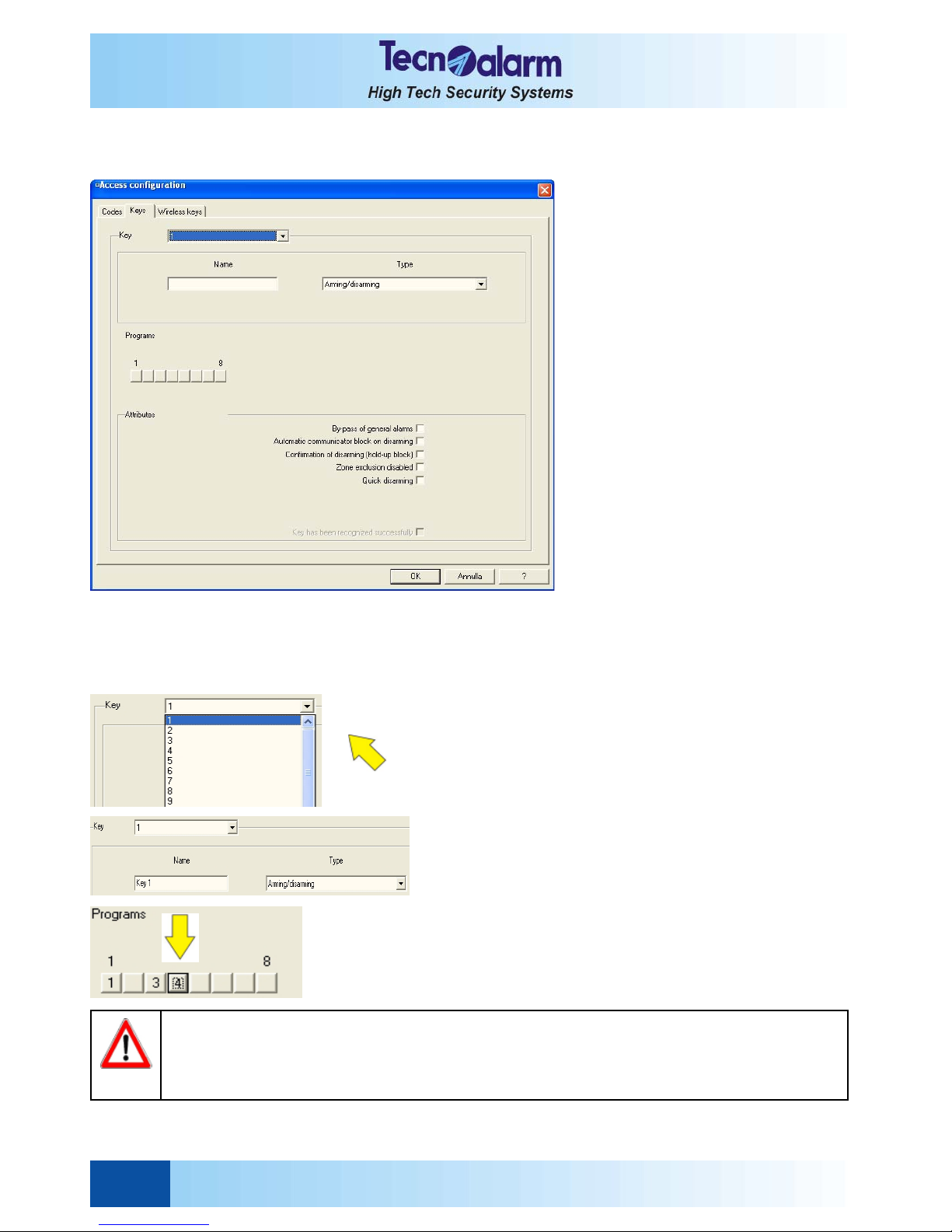
Programming of access codes and keys Installer Manual - TP8-96 VIDEO
5-4
5. 2 PROGRAMMING OF THE KEYS
Open the access configuration tables and select the Key window. On the screen is viewed:
The key configuration table permits:
z Programming of the key name
z Association of the functions
z Association of the programs
z Programming of the attributes of the keys
SELECTION OF THE KEY
Select the item next to Key and scroll down the list
(1 to 100) then, click on the name of the key to be
programmed.
PROGRAMMING OF THE KEY
For every key the following parameters can be
programmed:
z Name or description (max. 16 caracters).
z Type, i.e. the function that is initiated upon
introduction of the key into the key reader (arming/
disarming or by-pass).
KEY-PROGRAM ASSOCIATION
The key will only be enabled to act on (arm/disarm or
partset) the associated programs (1 to 8).
To associate a program to the key click on the
corresponding item. The program number will be shown
as a confirmation of the association.
WARNING
If you use the key reader with minikeypad TP SK6N, for arming of the program, you will have to insert
the key into the key reader and enter the program number.
In addition to the key-program association it is indispensable to associate the programs to the key
reader, otherwise the introduction of the key will be ineffective.
Page 79
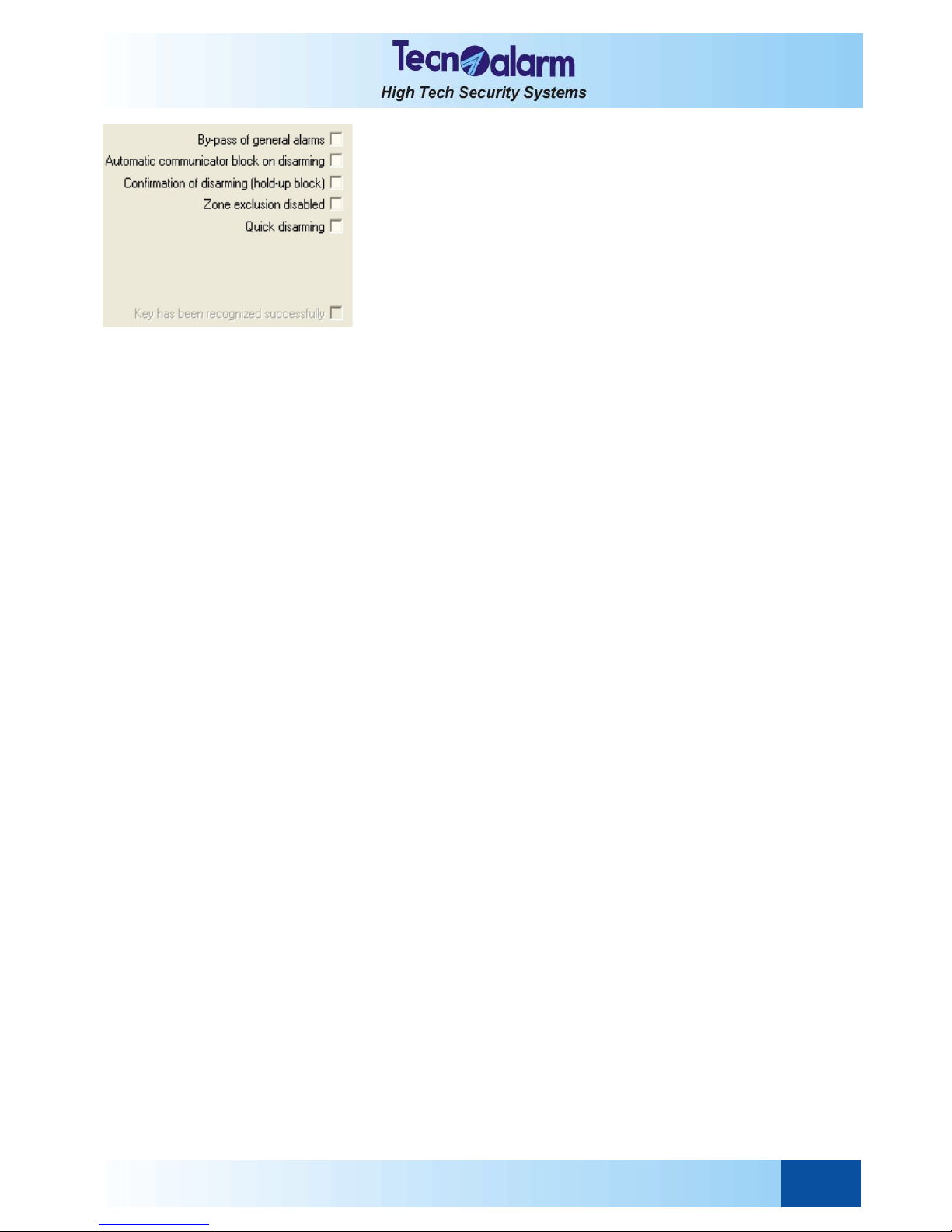
TP8-96 VIDEO - Installer Manual Programming of access codes and keys
5-5
PROGRAMMING OF THE ATTRIBUTES
To associate the attributes to the key check the relevant item.
z By-pass general alarms
If checked, the user will be entitled to arm the system even
in presence of a general alarm (i.e. tamper, low battery,
power failure, supervision, trouble modules)
z Automatic communicator block on disarming
If checked, upon disarming of the system (by inserting the
key into the key reader) the active telephone channels (and
those queued up) are blocked automatically.
z Confirmation of disarming (hold-up block)
Activates the hold-up function on the key. In this case,
disarming by this key will have to be confirmed by entering of
a valid user code within a determined period of time
(disarming confirmation delay), otherwise a silent hold-up
alarm will be released.
z Zone exclusion disabled
If checked, the user will not be entitled to arm the control
panel excluding some of the zones (both voluntary and
automatic zone exclusion are disabled). The control panel
will be armed in any case, and if there are open zones, the
alarm will be released.
z Quick disarming
On introduction of the electronic key into the key reader,
while the control panel is armed, all the associated programs
are disarmed. In this case the electronic key will arm/disarm
only the first program associated to it.
z Key has been recognized successfully
Indicates if the selected key corresponds to a memorized
one. If the item is checked, the key has been recognized.
Repeat the procedure for all the user codes (1 to 100).
See § 5.4 for explanatory notes.
Press:
z OK to confirm and quit
z Abandon to quit without saving
Page 80
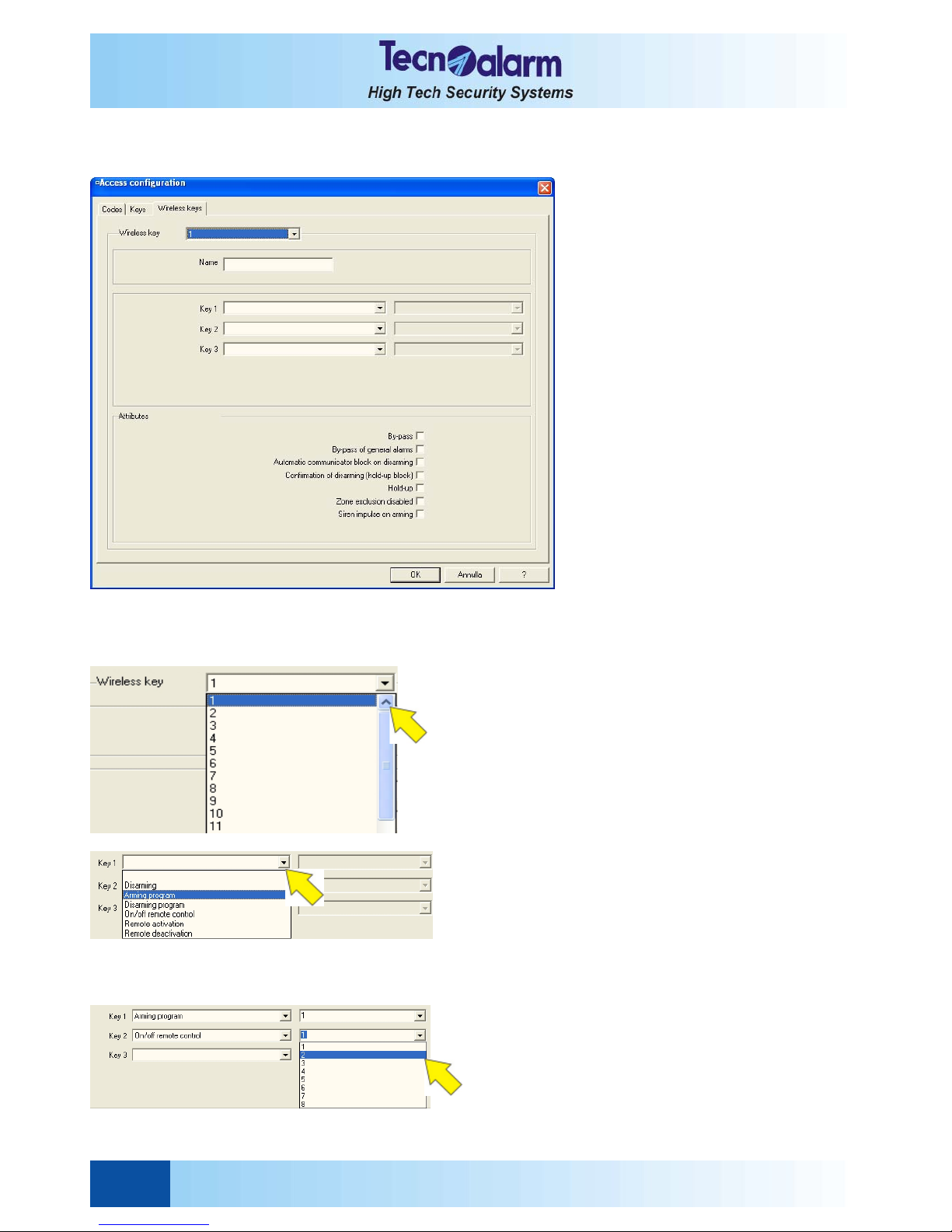
Programming of access codes and keys Installer Manual - TP8-96 VIDEO
5-6
5.3 PROGRAMMING OF THE WIRELESS KEYS
Open the access configuration tables and select the Wireless key window. On the screen is viewed:
The wireless keys configuration table permits:
z Programming of the wireless key name
z Association of the functions to the function keys
z Programming of the attributes of the wireless keys
SELECTION OF THE WIRELESS KEY
Select the item next to Wireless key and scroll down the
list then click on the name of the wireless key to be
programmed.
PROGRAMMING OF THE WIRELESS KEY NAME
For every wireless key a 16 caracters name or
description can be programmed.
WIRELESS KEY-FUNCTIONS ASSOCIATION
Each wireless key provides 3 function keys that are
individually programmable with the following functions:
z Disarming
Disarming of all the programs armed by wireless key.
z Arming program
Arming of the associated program (1 to 8).
z Disarming program
Disarming of the associated program (1 to 8).
z On/off remote controle
Toggling of the associated remote control (1 to 8).
z Remote activation
Activation of the associated remote control (1 to 16).
z Remote deactivation
Deactivation of the associated program (1 to 16).
To associate a function to one of the function keys select
the item next to the number of the function key and scroll
down the list, then select from the device to be activated
or deactivated by clicking on the item and scrolling down
the list.
Page 81
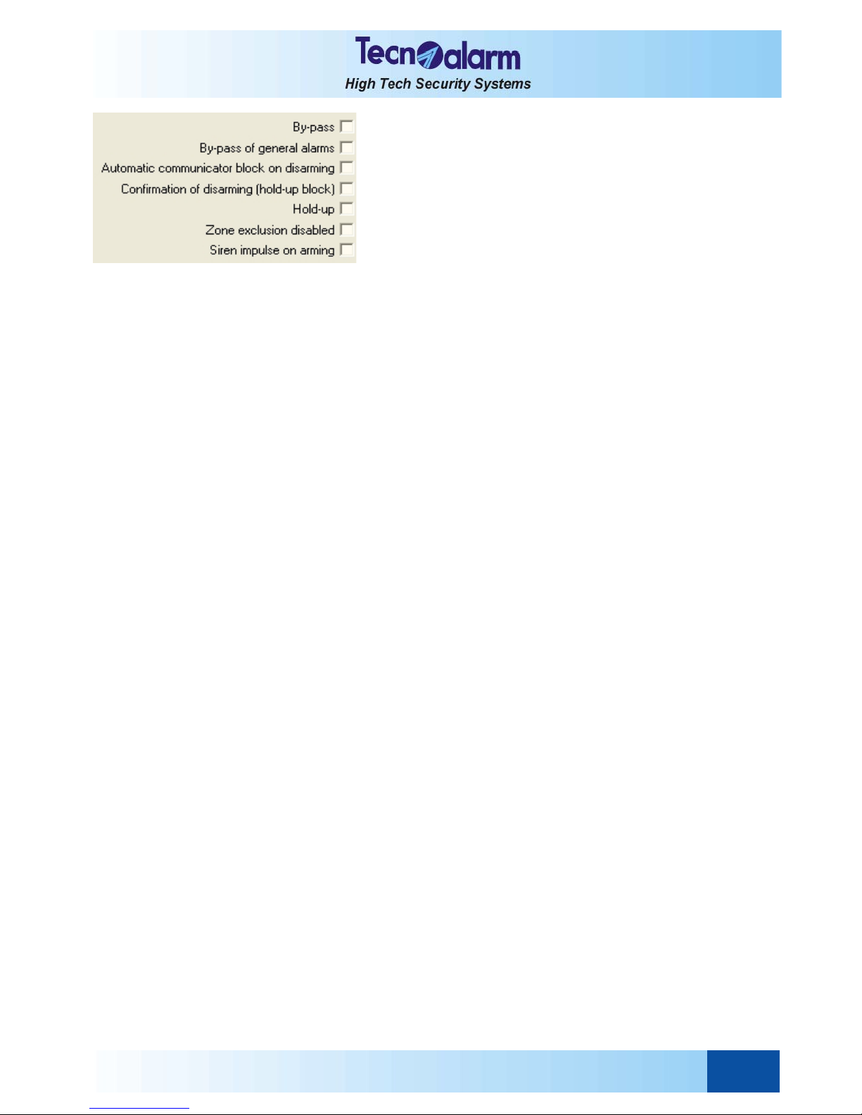
TP8-96 VIDEO - Installer Manual Programming of access codes and keys
5-7
PROGRAMMING OF THE ATTRIBUTES
To associate the attributes to the key check the relevant item.
z By-pass
If checked, the meaning of arming and disarming of the
associated programs change:
• Arming program becomes Start by-pass program
• Disarming program becomes End by-pass program
• Disarming becomes End of by-pass
z By-pass general alarms
If checked, the user will be entitled to arm the system even
in presence of a general alarm (i.e. tamper, low battery,
power failure, supervision, trouble modules)
z Automatic communicator block on disarming
If checked, upon disarming of the system (pressing the
corresponding function key) the active telephone channels
(and those queued up) are blocked automatically.
z Confirmation of disarming (hold-up block)
Activates the hold-up function on the wireless key. In this
case, disarming by this wireless key will have to be
confirmed by entering of a valid user code within a
determined period of time (disarming confirmation delay),
otherwise a silent hold-up alarm will be released.
z Hold-up
If checked, it is possible to release a hold-up (panic) alarm
and activate the relative output by pressing simultaneously
the keys 2 and 3 of the wireless key.
z Exclusion disabled
If checked, the user will not be entitled to arm the control
panel excluding some of the zones (both voluntary and
automatic zone exclusion are disabled). The control panel
will be armed in any case, and if there are open zones,
the alarm will be released.
z Siren impulse on arming
If enabled, on arming of the control panel, the siren is
actived for a few seconds (1 impulse).
Repeat the procedure for all the wireless keys (1 to 100).
See § 5.4 for explanatory notes.
Press:
z OK to confirm and quit
z Abandon to quit without saving
Page 82
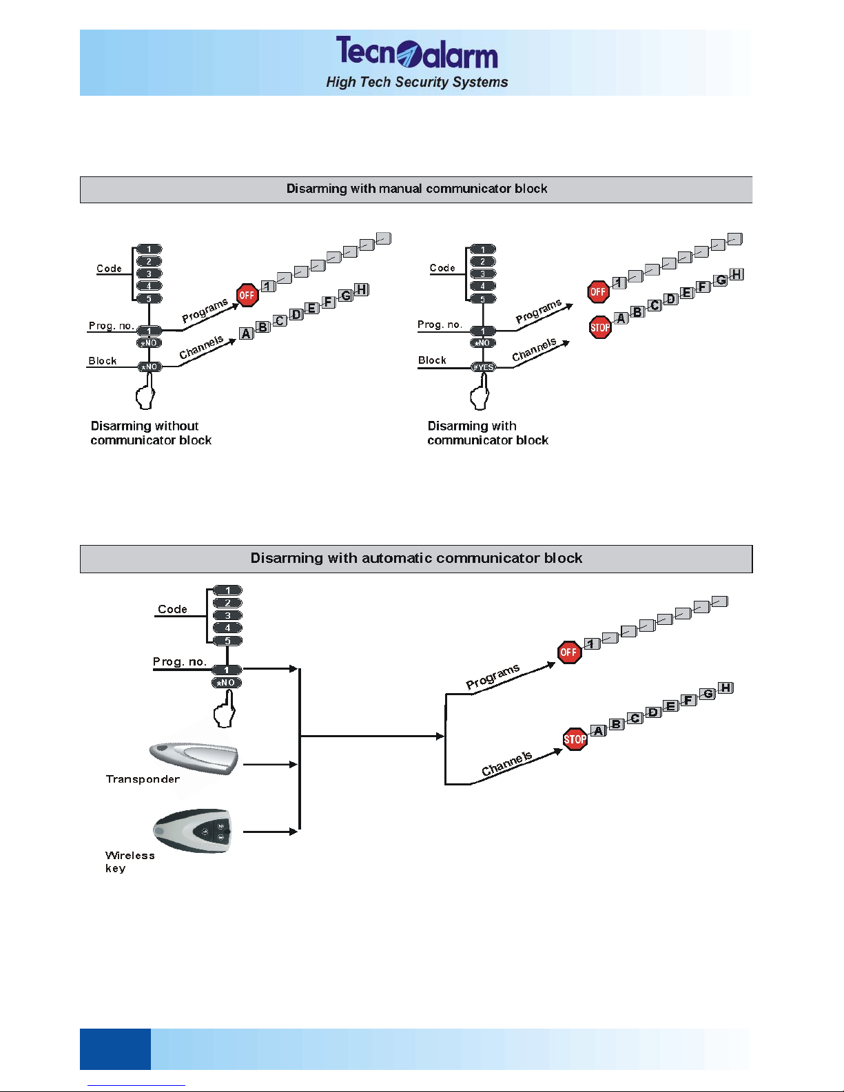
Programming of access codes and keys Installer Manual - TP8-96 VIDEO
5-8
5.4 EXPLANATORY NOTES
DISARMING IN CASE OF ALARM WITH MANUAL COMMUNICATOR BLOCK
The below example illustrates disarming with manual communicator block (see programming of the attributes page 5-2).
DISARMING IN CASE OF ALARM WITH AUTOMATIC COMMUNICATOR BLOCK
The below example illustrates disarming with automatic communicator block (see programming of the attributes page
5-2, 5-5 and 5-7).
Page 83
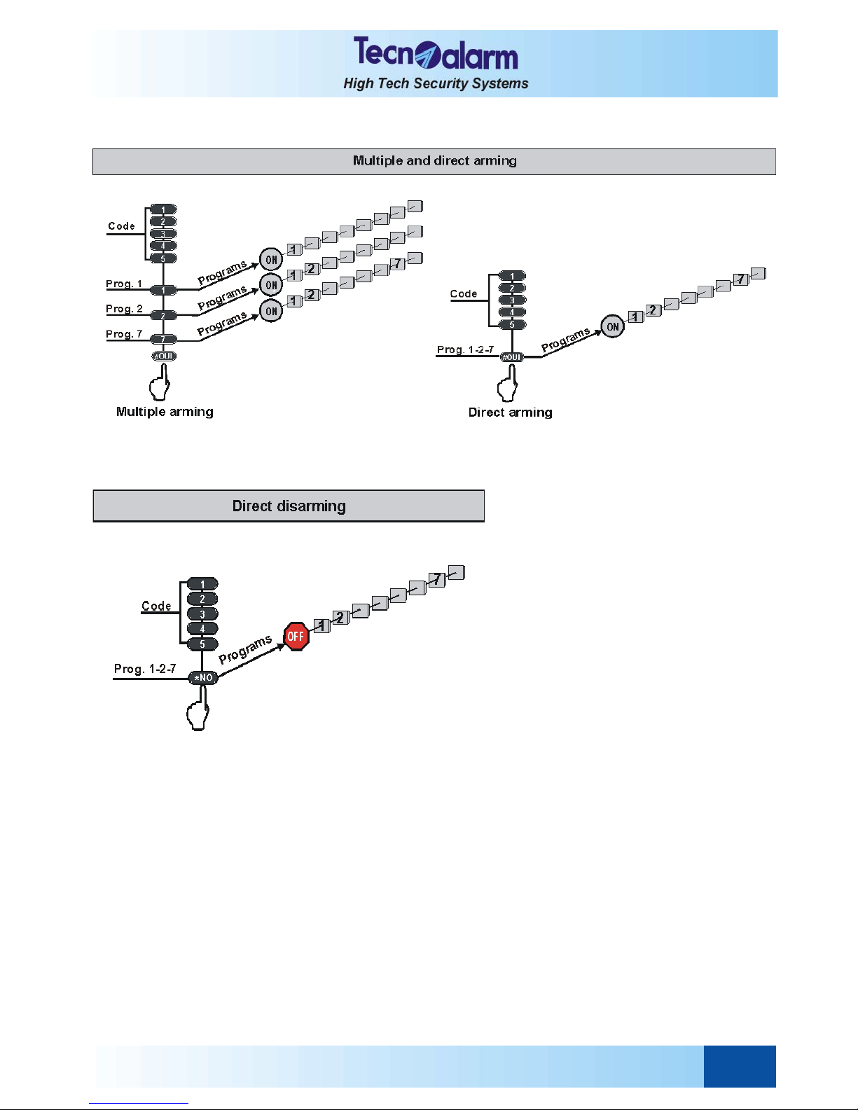
TP8-96 VIDEO - Installer Manual Programming of access codes and keys
5-9
MULTIPLE AND DIRECT ARMING
The below example multiple (see programming of the attributes page 5-3) and direct arming.
DIRECT DISARMING
The below example illustrates direct disarming (see programming of the attributes page 5-3).
Page 84
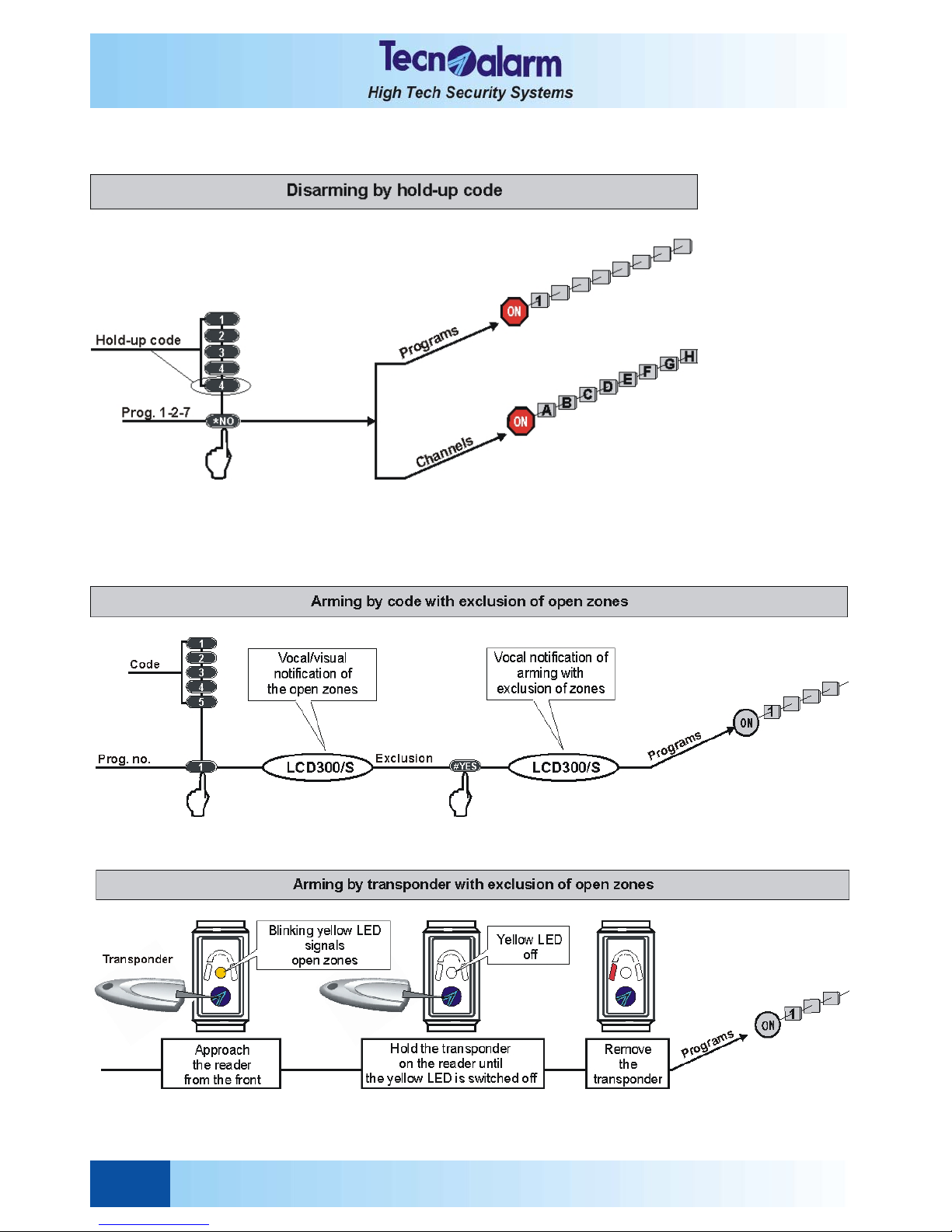
Programming of access codes and keys Installer Manual - TP8-96 VIDEO
5-10
DISARMING UNDER DURESS
The below example illustrates disarming under duress, i.e. by hold-up code (see programming of the attributes
page 5-2)
ARMING WITH EXCLUSION OF OPEN ZONES
The below examples illustrate arming with exclusion of the open zones (see programming of the attributes
page 5-3, 5-5 and 5-7).
Page 85
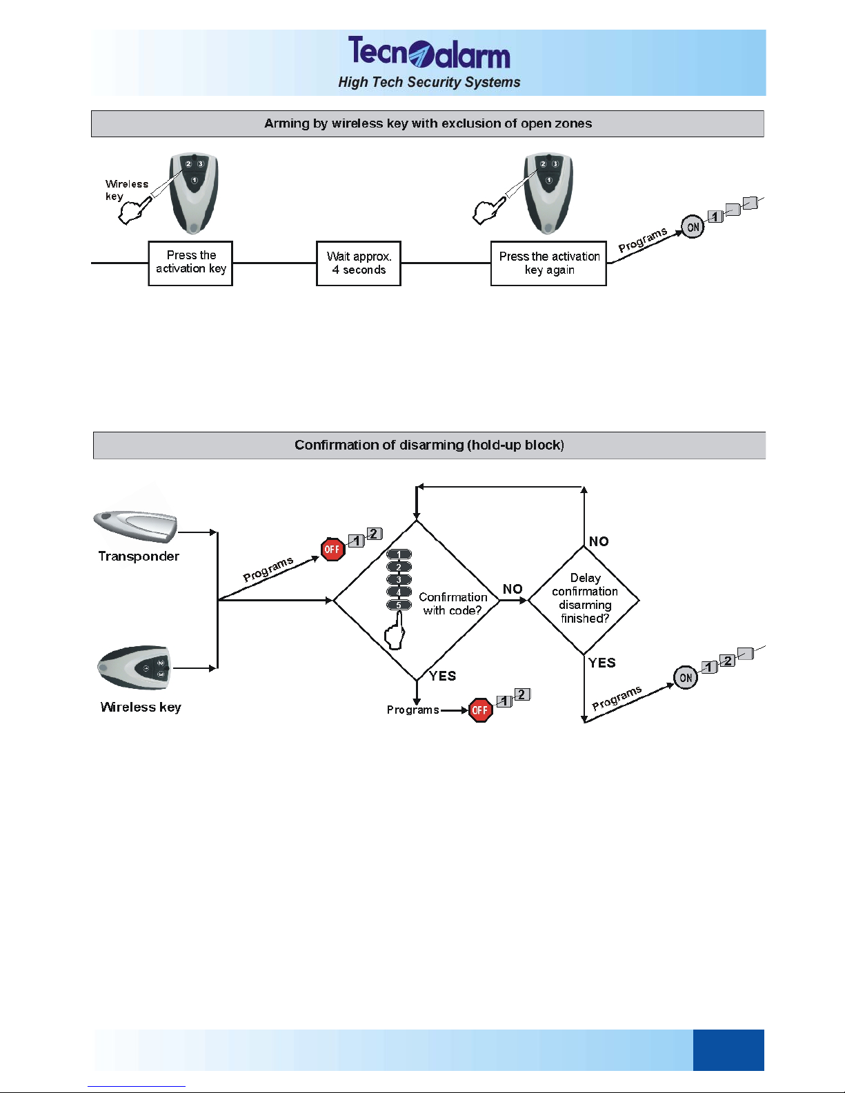
TP8-96 VIDEO - Installer Manual Programming of access codes and keys
5-11
CONFIRMATION OF DISARMING
The below example illustrates the confirmation of disarming function, i.e. hold-up block (see programming of the
attributes page 5-5 and 5-7). If the confirmation of disarming attribute is enabled, disarming by the transponder or
wireless key in question must be confirmed by a valid code within a determined period of time, otherwise a silent holdup alarm is released.
Page 86

Programming of access codes and keys Installer Manual - TP8-96 VIDEO
5-12
Page 87
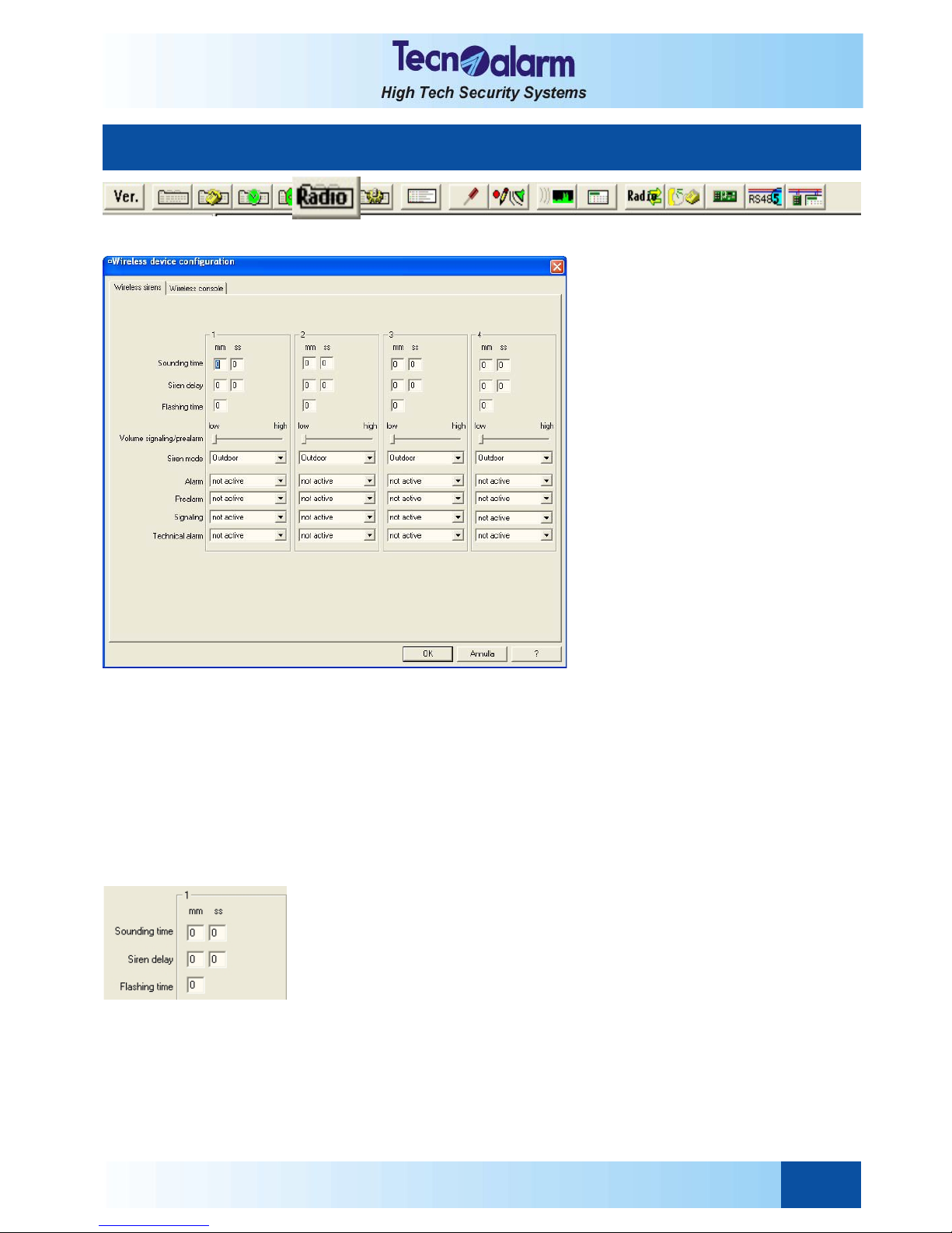
TP8-96 VIDEO - Installer Manual Programming of wireless devices
6-1
6. PROGRAMMING OF WIRELESS DEVICES
Permits programmming of the wireless devices. Clicking on the above icon, on the screen is viewed:
The tables of the wireless device configuration permit:
z Programming of the wireless sirens
z Programming of the wireless consoles
6.1 PROGRAMMING OF THE WIRELESS SIRENS
The control panel manages max. 4 wireless sirens which are individually programmable according to the following
parameters:
z Time parameters (sounding, siren delay, duration flashing light)
z Functioning (volume of sounding, siren mode)
z Activation mode (not active, bell, flashing light, siren+flashing light) for alarm, prealarm, signaling or technical
alarm.
PROGRAMMING OF THE TIME PARAMETERS
To program the time parameters click on the items and enter
the values requested:
z Sounding time (mm:ss)
Determines the sounding time in case of alarm.
z Siren delay (mm:ss)
Determines the interval between the detection of an alarm
and the activation of the siren.
z Flashing time (mm:ss)
Determines the blinking time in case of alarm or technical
alarm.
Page 88
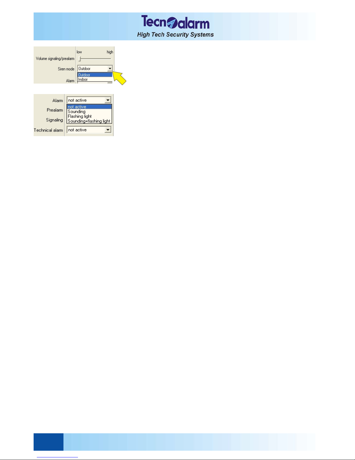
Programming of wireless devices Installer Manual - TP8-96 VIDEO
6-2
PROGRAMMING OF FUNCTIONING
z Volume signaling/prealarm
z Volume signaling/prealarm
To set volume of sounding for prealarm or signaling move
the cursor. Volume of sounding for alarm is always set
at the maximum.
z Siren mode
The siren can be programmed so as to work either as
an indoor or an outdoor siren.
PROGRAMMING OF THE ACTIVATION MODE
Activation of the wireless sirens can be programmed individually
for the following events:
z Alarm
z Prealarm (during the entry time)
z Signaling (arming or disarming)
z Technical alarm
The following activation modes can be programmed:
z Not active (the siren is not activated at all)
z Sounding (the horn is activated for the sounding time
programmed)
z Flashing light (the flashing light is activated for the time
programmed)
z Sounding + flashing light (both the horn and the flashing
light are activated for the time programmed)
Press:
z OK to confirm and quit
z Abandon to quit without saving
Page 89
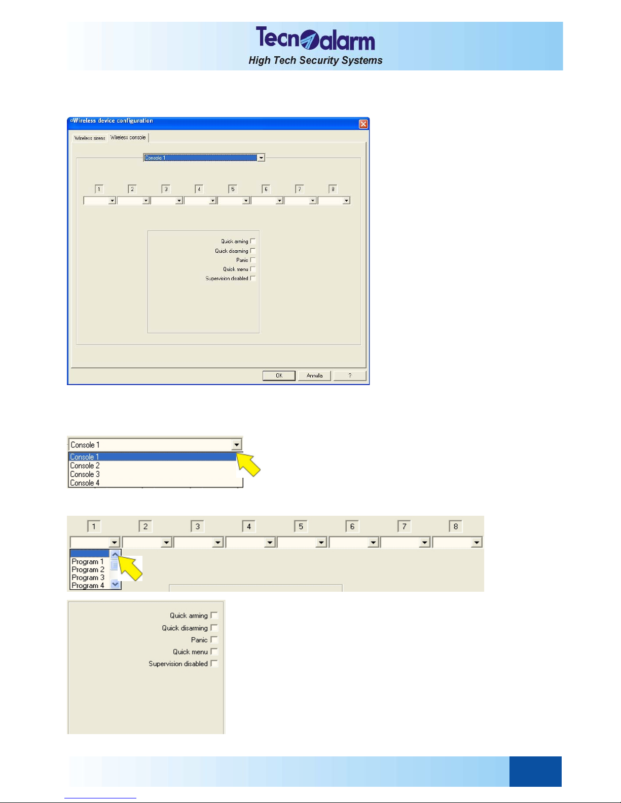
TP8-96 VIDEO - Installer Manual Programming of wireless devices
6-3
6.2 PROGRAMMING OF THE WIRELESS CONSOLES
Open the wireless device configuration tables and select the Wireless consoles window. On the screen is viewed:
The control panel permits the management of max. 4 wireless consoles which are individually programmable according
to the followings parameters:
z Association of the programs
z Programming of the attributes of the consoles
SELECTION OF THE CONSOLE
Select the corresponding item and scroll down the list then,
click on the name of the console to be programmed.
LED-PROGRAM ASSOCIATION
To associate the programs to the LED of the console, select the
corresponding item, scroll down the list ant select the program.
PROGRAMMING OF THE ATTRIBUTES
To associate the attributes of the console select the
corresponding item.
z Quick arming
Permits arming of the associated programs with quick
arming command (i.e. *(star) key followed by the
program number and the hash key (#YES)).
z Quick disarming
Permits disarming of the associated programs with quick
disarming command (i.e. *(star) key followed by the
program number and again the star key (*NO).
Page 90

Programming of wireless devices Installer Manual - TP8-96 VIDEO
6-4
z Panic
In case of hold-up or medical emergency permits the activation of a panic alarm pressing the arrow-up and arrowdown keys (yw) simultaneously.
z Quick menu
Enables the quick menu on the console. It permits activation/deactivation of the remote controls without code.
z Supervision disabled
Disables the supervision/test transmission of the console.
Repeat the operations for all the wireless consoles (1 to 4).
Press:
z OK to confirm and quit
z Abandon to quit without saving
Page 91
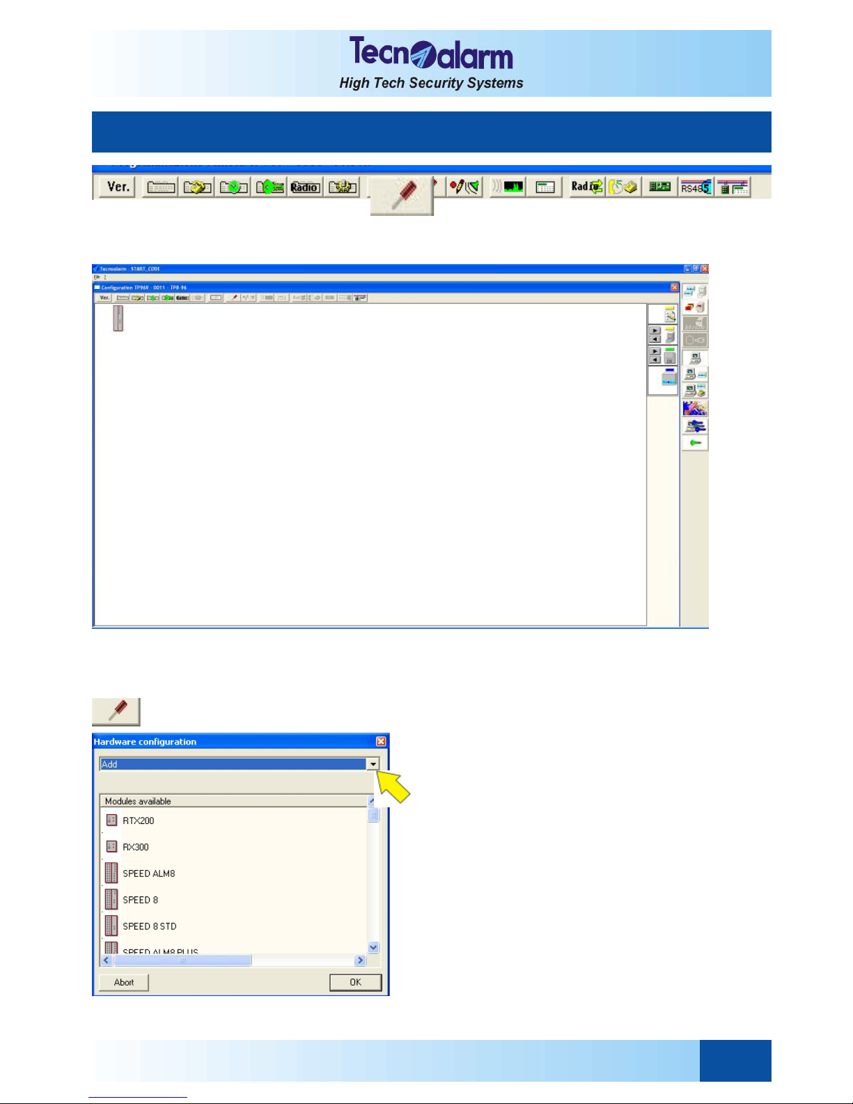
TP8-96 VIDEO - Installer Manual Hardware configuration
7-1
7. HARDWARE CONFIGURATION
Permits the hardware configuration of the control panel, i.e. addition or deletion of the hardware modules to/of the
viewed configuration. Click on the configuration icon, on the screen is viewed:
7.1 ADDITION OR DELETION OF MODULES
Enter hardware configuration by clicking on the opposite
icon.
ADDITION OF MODULES
Select Add in the hardware configuration window and
select the module to be connected, e.g. SPEED 8 STD.
Page 92
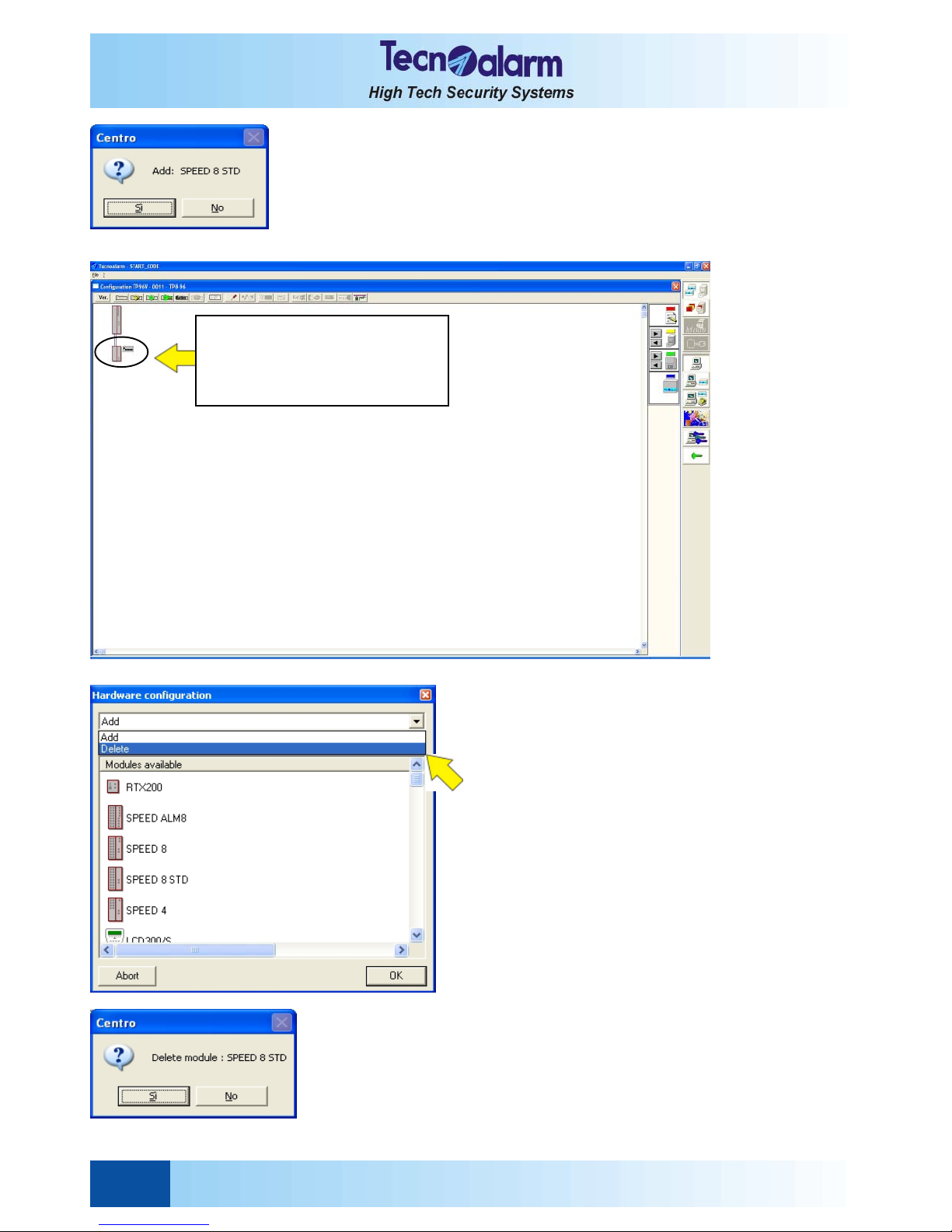
Hardware configuration Installer Manual - TP8-96 VIDEO
7-2
On the screen is viewed the opposite message.
Commands available
z Yes to confirm the addition of the module selected
z No to undo the addition of the module selected
Click on OK to confirm and quit hardware configuration.
Click on Abort to undo the changes to the hardware
configuration viewed.
If you confirm the addition of the module, it is added to
the system configuration viewed.
DELETION OF MODULES
Select Delete in the hardware configuration window and
select the module to be deleted, e.g. SPEED 8 STD.
On the screen is viewed the opposite message.
Commands available
z Yes to confirm the deletion of the module
selected
z No to undo the deletion of the module
selected.
On the screen is viewed the beside image.
Click on OK to confirm and quit hardware configuration.
Click on Abort to undo the changes to the hardware
configuration viewed.
If you confirm the deletion of the module, it is removed
from the system configuration viewed.
The new module is added to the
system configuration viewed.
Next to the module the
dipswitch address is shown.
Page 93
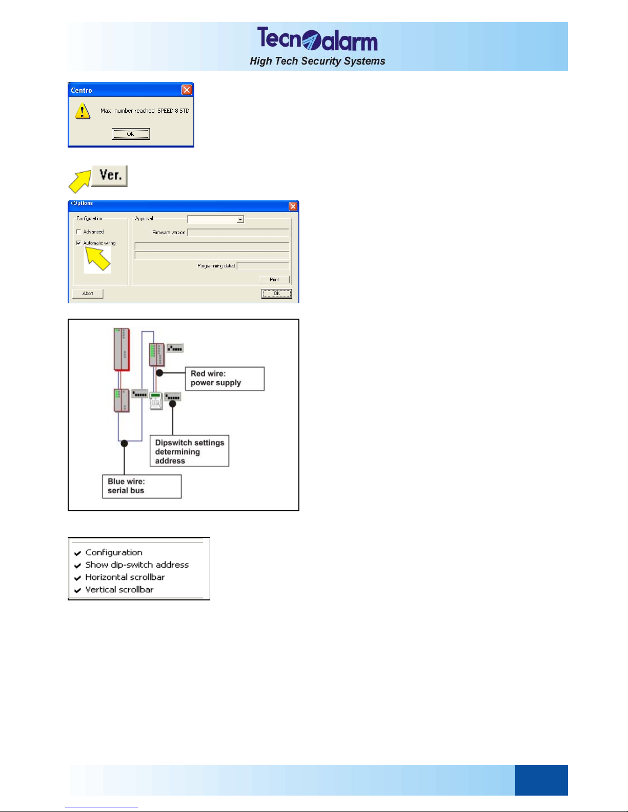
TP8-96 VIDEO - Installer Manual Hardware configuration
7-3
LIMITS OF THE SYSTEM
The program automatically controls the system's
hardware limits, i.e. the maximum number of devices
which can be connected to the control panel (zone
expansions, consoles, wireless devices, etc.).
When a group of devices has reached the system's
limits (ex. SPEED 8 STD), on the screen is viewed the
opposite image and the addition is not possible.
Click OK to close the window.
GRAPHICAL REPRESENTATION OF THE SYSTEM
Connection and power supply
Even if hardware configuration is possible without
automatic wiring, the Automatic wiring option must be
enabled (checked). In this case, connections and power
supply are automatically designed.
Click on the beside icon, on the screen is viewed the
successive image.
Commands available
z OK to confirm and continue hardware
configuration
z Abandon to abandon hardware configuration
The beside schema is the graphical representation of
the system.
Connection
The connections are represented in an unifilar mode.
The red lines represent power supply and the blue ones
are the RS485 serial line.
Siren bus
This schema represents only the RS485 serial line,
therefore, to simplify the graphic, the siren bus are
connected to RS485 serial line too.
But on the real wiring, the siren bus must be connected
only to the Siren bus.
Wireless devices
All the wireless devices, excepted the receiver modules,
are represent without any type of connections to the
serial line.
OPTIONS OF VIEWING
The screen is delimited by the menu bar in the upper
part and by the scrollbar in the lower part.
With a left click of the mouse, everywhere on the
worktop, the window of the viewing options appears
(beside image).
Options available
z Configuration
Permits viewing of the selection keys of the
programming menus (upper and lateral bar).
z Show dip-switch address
Permits viewing of the dip having serial address of
the viewed devices on the worktop.
z Horizontal scrollbar
Permits to visualize or to hide the horizontal
scrollbar.
z Vertical scrollbar
Permits to visualize or to hide the vertical
scrollbar.
Click on the option to enable or disable it.
Page 94

Hardware configuration Installer Manual - TP8-96 VIDEO
7-4
Page 95
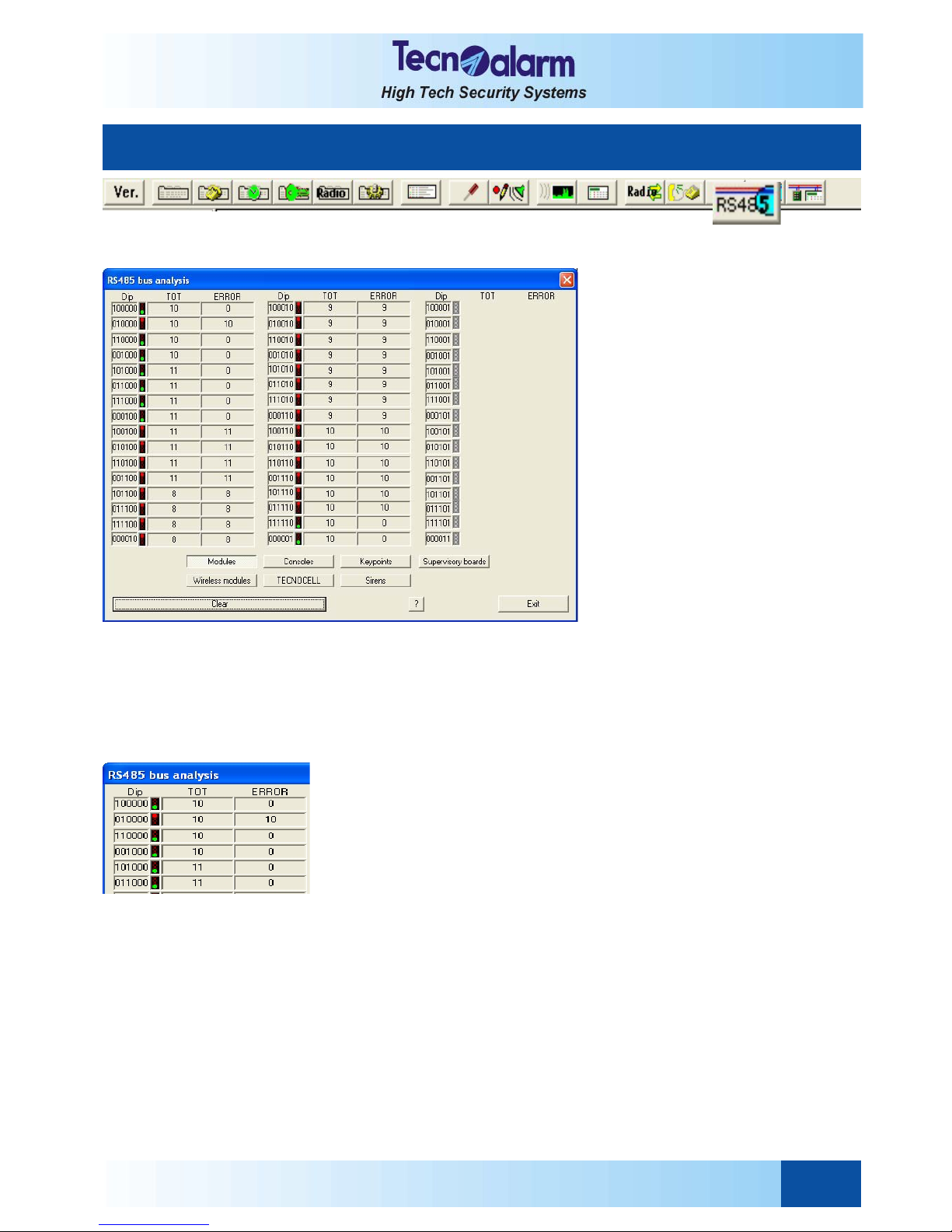
TP8-96 VIDEO - Installer Manual Bus analysis
8-1
Permits the constant control of theRS485 serial bus where the devices which composed the system are connected.
By clicking on the above icon, on the screen is viewed :
The RS485 bus analysis table permits the communication monitoring in order to verify coherence and exactitude of the
datas.
The RS485 bus analysis table permits:
z Viewing of the device addresses
z Viewing of the total counter (TOT) and of the error counters (ERROR)
z Signaling of the communication errors
z Selection of the group to be controlled
DIP
Permits viewing of the device addresses.
TOT
Each communication is analized, totalized and recorded by the TOT total
counter.
ERROR
Each communication considered invalid is recorded, therefore totalizes, into the
ERROR counter (i.e. communication errors).
SIGNALING
The RS485 serial bus analysis connects the TOT and the ERROR counters in
order to determine the data communication reliability between CPU and devices;
it calculates the percentage of errors and classify it using the signaling of a
traffic light. Signaling are the following:
Off signal = peripheral absent, connection absent or permanently
excluded
Green signal = reliable datas, i.e. insignificant error (less than 1%)
Yellow signal = percentage of error from 1 to 3%, i.e. negligible
Red signal = percentage of error highter than 3%, i.e. critical.
According to the beside example, the peripheral with the address 1 is
present on the installation and signals none error. Therefore the signal is green.
By contrast, the peripheral with the address 01 is not present on the
installation so the number of errors is equal to the number of communications.
As a result, the signal is red.
8. RS485 SERIAL BUS ANALYSIS
Page 96
Bus analysis Installer Manual - TP8-96 VIDEO
8-2
The counter Clear key causes the reset of all the counters
of all the groups.
It is recommended to reset the counters when the
installation procedure has been completed.
Then press:
z Exit to quit the RS485 serial bus table
Page 97

TP8-96 VIDEO - Installer Manual Special procedures
A-1
APPENDIXAPPENDIX
APPENDIXAPPENDIX
APPENDIX
SPECIAL PRSPECIAL PR
SPECIAL PRSPECIAL PR
SPECIAL PR
OCEDURESOCEDURES
OCEDURESOCEDURES
OCEDURES
TP8-96 VIDEOTP8-96 VIDEO
TP8-96 VIDEOTP8-96 VIDEO
TP8-96 VIDEO
Page 98

Special procedures Installer Manual - TP8-96 VIDEO
A-2
Page 99
TP8-96 VIDEO - Installer Manual Special procedures
A-3
A. SPECIAL PROCEDURES
A.1 RESET OF THE DEFAULT CODES
When the control panel is in stand-by (date and time viewed), to reset the default
codes, procede as follows:
z Remove the jumper JP3.
z The red, yellow and green LED of the electronic board are switched off.
z On the display of the console Line ! ABSENT ! is viewed and all the LED of the
console are blinking.
z When the firmware version of the console is viewed on the display of the console,
press the EXIT key several times.
On the display is viewed Code Deleted.
z Reinsert the jumper JP3 and verify that the yellow LED is switched on.
After a few seconds, the control panel returns to stand-by and on the display
reappears date and time signaling.
(c) Tecnoalarm
Ver 0.7.05 ENG
Tue 12 JAN 10
Work. 10:45
Code
Deleted
Tue 12 JAN 10
Work. 10:45
Line
! ABSENT !
WARNING
The reset of the default codes will affect all the codes of the system as well as the code length:
z Default installer code 54321
z Default master code 12345
z Default standard user codes 00000 (unvalid code)
z Default code length 5 digits
Page 100
Special procedures Installer Manual - TP8-96 VIDEO
A-4
A.2 COMPLETE DELETION OF SYSTEM
CONFIGURATION (RESET OF DEFAULT SETTINGS)
When the control panel is in stand-by (date and time viewed), to reset the default
configuration, procede as follows:
z Remove the jumper JP3.
z The red, yellow and green LED of the electronic board are switched off
z On the display of the console Line ! ABSENT ! is viewed and all the LED of the
console are blinking
z When the firmware version of the system will be viewed, press the star key
(*NO) several times.
On the display will be viewed Config. Deleted.
z Reinsert the jumper JP3
After a few seconds, the control panel returns to stand-by and on the display
reappears date and time signaling.
WARNING
After the deletion of the system configuration, the control panel will be set with all the default settings
(i.e. no telephone number, no zone configuration, no function programmed) and the default codes
as well as the default code length:
z Default installer code 54321
z Default master code 12345
z Default standard user codes 00000 (unvalid code)
z Default code length 5 digits
(c) Tecnoalarm
Ver 0.7.05 ENG
Tue 12 JAN 10
Work. 10:45
Config.
Deleted
Tue 12 JAN 10
Work. 10:45
Line
! ABSENT !
 Loading...