

Tecnoalarm TP8-64, TP8-64 MET User Manual
USER MANUALUSER MANUAL
USER MANUALUSER MANUAL
USER MANUAL
Release: 3.0
Update: June 2009
Language: English
FW version: 2.3
TP8-64TP8-64
TP8-64TP8-64
TP8-64
TP8-64 METTP8-64 MET
TP8-64 METTP8-64 MET
TP8-64 MET
8 - 64 ZONES
CONTROL PANEL

II
User Manual - TP8-64
The features of the control panel can be subject to change without notice.
Unauthorized reproduction or distribution of this manual, or any portion of it, on any device and in any form, is
prohibited.
The contents of this manual may be subject to change without notice.

III
TP8-64 - User Manual
CONFORMITY
Hereby, Tecnoalarm srl declares that the present equipment is in compliance with the essential requirements and
other relevant provisions of the R&TTE 1999/05/EC directive.
The declaration of conformity is available on the website: www.tecnoalarm.com.

IV
User Manual - TP8-64

TP8-64 - User Manual Index
1
INDEX
1. GENERAL FEATURES
1.1 CODES 1-1
1.1.1 Master menu 1-1
1.1.2 Standard user menu 1-2
1.2 ELECTRONIC KEYS 1-2
1.3 CONTROL BY TELEPHONE 1-2
1.3.1 Skip answering machine 1-2
1.4 PROGRAMS 1-3
1.5 COMPOSITION OF THE CONTROL PANEL 1-3
2. SIGNALING
2.1 LED SIGNALING OF THE CONSOLES 2-1
2.1.1 Alarm LED - Red 2-3
2.1.2 Control LED - Yellow 2-5
2.2 LED SIGNALING OF THE TP SDN ELECTRONIC KEYPAD 2-6
2.2.1 Program alarm LED - Yellow 2-6
2.2.2 General alarm LED - Red 2-6
2.2.3 Keypad status LED - Green 2-7
2.2.4 Program status LED - Red 2-7
2.3 LED SIGNALING OF THE TP SK6N KEY READER WITH MINI KEYPAD 2-8
2.3.1 Program alarm LED - Red 2-8
2.3.2 General alarm LED - Red 2-8
2.3.3 Program status LED - Yellow 2-9
2.3.4 Zone status LED - Yellow 2-9
2.3.5 Key LED - Green 2-9
2.4 LED SIGNALING OF THE ATPK KEY READER 2-10
2.4.1 Program status LED - Red, yellow, green 2-10
2.4.2 Program and general alarm LED - Yellow 2-10
2.5 RESET OF ALARM MEMORY SIGNALING 2-11
2.5.1 Reset of LED signaling with master code 2-11
2.5.2 Reset of LED signaling with installer code (tamper LED signaling) 2-11
3. PROGRAMMING (MASTER CODE REQUIRED)
3.1 ACTIVATION/DEACTIVATION REMOTE CONTROLS 3-3
3.2 CLOCK SETTING 3-3
3.3 FUNCTIONS 3-3
3.4 CREATION/MODIFICATION OF THE PROGRAMS 3-3
3.5 TIMERS AND ACCESS PERIODS 3-4
3.5.1 Timers 3-4
2.5.2 Access periods 3-5
3.6 PROGRAMMING OF THE TELEPHONE PARAMETERS 3-6
3.6.1 Settings 3-6
3.6.2 PABX switchboard 3-6
3.6.3 Channels (A...H) 3-7
3.6.4 Call back 3-7
3.6.5 Mobile phone 3-7
3.7 PROGRAMMING OF THE CODES 3-8
3.7.1 Master code 3-8
3.7.2 Standard user codes 3-9
3.8 PROGRAMMING OF THE KEYS 3-10
3.8.1 Access periods 3-10
3.8.2 Programs 3-10

Index User Manual - TP8-64
2
3.8.3 Attributes 3-11
3.8.4 Learning 3-11
3.9 PROGRAMMING OF THE WIRELESS KEYS 3-11
3.9.1 Periods 3-11
3.9.2 Association buttons 3-12
3.9.3 Attributes 3-12
3.9.4 Learning 3-12
3.10 PROGRAMMING OF THE CONSOLES 3-13
3.11 EXCLUSION OF MODULES/ZONES 3-13
3.11.1 Exclusion of zones 3-13
3.12 TEST 3-14
3.12.1 Zone test 3-14
3.12.2 Indoor siren test 3-14
3.12.3 Outdoor siren test 3-14
3.12.4 Viewing of the firmware version 3-14
3.12.5 Viewing of the vocabulary version 3-14
3.12.6 Viewing of the LED status 3-14
3.12.7 GSM module test 3-15
3.13 ENABLING OF REMOTE ACCESS 3-15
4. CONTROL BY CONSOLE
4.1 ARMING 4-4
4.1.1 Arming with master code 4-6
4.1.2 Arming with standard user code 4-7
4.1.3 Quick arming (if enabled) 4-7
4.1.4 Arming through key zone 4-8
4.1.5 Automatic arming 4-8
4.1.6 Arming during access periods 4-8
4.1.7 Arming denied 4-9
4.2 DISARMING 4-9
4.2.1 Disarming with master code 4-9
4.2..2 Disarming with standard user code 4-9
4.2.3 Disarming under duress (if enabled) 4-10
4.2.4 Quick disarming (if enabled) 4-10
4.2.5 Disarming through key zone 4-10
4.2.6 Automatic disarming 4-10
4.2.7 Disarming during access periods 4-10
4.3 BY-PASS 4-10
4.3.1 By-pass activation with code 4-10
4.3.2 Automatic by-pass activation 4-11
4.3.3 Activation of by-pass during the access periods 4-11
4.3.4 Deactivation of by-pass 4-11
4.3.5 Automatic deactivation of by-pass 4-11
4.3.6 Deactivation of by-pass on expiry of maximum by-pass time 4-11
4.4 ACTIVATION/DEACTIVATION REMOTE CONTROLS 4-12
4.5 MANUAL COMMUNICATOR BLOCK 4-12
4.6 VIEWING OF THE EVENT BUFFER 4-13
4.7 RESET OF LED SIGNALING 4-14
4.7.1 Reset of LED signaling with master code 4-14
4.7.2 Reset of LED signaling with installer code (tamper LED signaling) 4-14
QUICK COMMANDS - OPERATIONS WITHOUT CODE
4.8 RELEASE OF PANIC ALARM 4-15
4.9 VIEWING OF ZONE STATUS 4-15
4.10 VIEWING ALARM MEMORY 4-15

TP8-64 - User Manual Index
3
5. CONTROL BY KEYPOINT
5.1 CONTROL BY TP SK6N KEY READER WITH MINI KEYPAD 5-1
5.1.1 Arming 5-1
5.1.2 Disarming 5-3
5.1.3 By-pass 5-3
5.1.4 Release of panic alarm 5-4
5.2 CONTROL THROUGH TP SKN INTERFACE FOR ELECTRONIC KEYS AND
ATPK KEY READERS 5-4
5.2.1 Arming 5-4
5.2.2 Disarming 5-6
5.2.3 By-pass 5-7
5.3 SPECIAL OPERATING CONDITIONS 5-8
5.3.1 False key alarm 5-8
5.3.2 Simultaneous arming by several control units 5-8
5.3.3 Simultaneous arming with code and key 5-8
5.3.4 Automatic disarming for alarm 5-8
5.3.5 Automatic communicator block 5-8
5.3.6 Trouble/general alarm 5-8
5.4 CONTROL BY TP SDN ELECTRONIC KEYPAD 5-9
5.4.1 Arming 5-9
5.4.2 Disarming 5-11
5.4.3 By-pass 5-11
5.4.4 Special operating conditions 5-12
5.5 TX240-3 WIRELESS KEY 5-13
5.5.1 Arming 5-13
5.5.2 Disarming 5-13
5.5.3 By-pass 5-14
5.5.4 Learning 5-14
6. CONTROL BY TELEPHONE
6.1 CALL FOR SYSTEM STATUS CHECK 6-1
6.1.1 System status check 6-1
6.1.2 Arming/disarming 6-1
6.1.3 Remote activation/deactivation of devices 6-2
6.1.4 Remote digital verification RDV 6-2
6.1.5 Opening message 6-3
6.2 RECEPTION OF AN ALARM CALL 6-3

Index User Manual - TP8-64
4

TP8-64 - User Manual Notes
I
IMPORTANT NOTES
The system TP8-64 is very easy to use.
Thus, we recommend to arm the system every time you leave your rooms unattended, even if for short periods
of time.
For your own safety keep all the codes secret.
In case you are robbed of your keys or you lose them, contact your installer immediately for their replacement.
APPLICATION NOTES
When you are at home
Never leave the doors and windows open. If possible, arm the system partially in order to protect the perimeter
and the rooms that you do not use.
When you go out
Verify thoroughly that all the doors and windows protected are closed.
Verify on the console that the system is functioning correctly and that there is no alarm or error signaling
active.
Arm the system completely (all the programs needed to protect all the zones of the system).
When you go on holiday
Verify that all the batteries of the system have been checked and replaced with the frequency prescribed by
the installer.
Verify thoroughly that all the doors and windows protected are closed.
Arm the system for test and verify that it works correctly (sirens, detectors etc.).
Arm the system completely (all the programs needed to protect all the zones of the system).

Notes User Manual - TP8-64
II
TP8-64 - User Manual General Features
1-1
1. GENERAL FEATURES
The control panel TP8-64 is a new generation microprocessor-based control panel. It controls a minimum of 8 and a
maximum of 64 zones, which can be freely associated to the inputs of the CPU board, the plug-in expansion module,
the input modules connected via serial line and the plug-in radio expansion.
The control panel is programmed by the installer using a PC or an LCD console (LCD200 or LCD300/S).
The holder of the master code can execute simple settings through LCD console whereas all of the users can
arm/disarm or partset the system by code or electronic key.
1.1 CODES
The system distinguishes two user levels:
Master
The master code permits limited programming as well as arming/disarming and partset
of the system. This code is usually reserved to the owner of the system as it can
program or modify the standard user codes.
Enter the master code to enter the master menu.
The default code is 12345, and can be modified by the master.
Standard user
The standard user codes (max. 62) permit merely arming/disarming and partset of the
system.
Enter the user code to arm/disarm or partset the programs it has been enabled for.
The standard user codes are programmed and modified by the master, there are no
default settings.
1.1.1 MASTER MENU
The master code permits:
z Date and time setting
z Association of chime to the zones (acoustic open zone signaling with the
program in stand-by)
z Creation and modification of the programs
z Programming of 16 timers for automatic arming
z Programming of 8 access periods (periods of time during which the codes and
keys are enabled)
z Programming of the telephone parameters:
• Enabling of the answering mode (answering to incoming calls)
• Defines the number of ringback
• Programming of the PABX number if the control panel is connected behind
a PABX internal switch board
• Programming of the telephone numbers (2 numbers per channel)
• Volontary execution of a call back
• Enabling of the answering mode on the GSM interface TECNOCELL
• Programming of the emergency number of the GSM interface (to be called if the
communication between the control panel and the communicator is interrupted)
z Programming or modification of the values of the user codes (master and standard
user codes 1...62) and the functions they are enabled for
z Programming of the electronic keys (1...32)
z Programming of the wireless keys (1...32)
z Enabling of the consoles connected (1...15)
z Programming of the volume of sounding of the console for the vocal message
z Volontary exclusion of modules (e.g. in case of bad functioning)
z Enabling of remote access (permitting the installer to control or program the
system via telephone line using the remote control software)
z Access to ambiente di test per il controllo della funzionalità della centrale.
z Remote control (activation/deactivation of 1...8 devices)
z Arming/disarming of the programs 1...8
z Total disarming (disarming of all programs)
z Partial disarming (disarming of some of the programs armed)
z Quick arming/disarming (using the keys # and *)
z Viewing of the contents of the event buffer
z Erasement of the events stored
z Communicator block (interruption of the active telephone calls)
LCD200
LCD300/S
General Features User Manual - TP8-64
1-2
1.1.2 STANDARD USER MENU
The standard user codes (1...62) do not permit programming but merely:
z Remote control (activation/deactivation of 1...8 devices)
z Arming/disarming of the programs 1...8
z Total disarming (disarming of all programs)
z Partial disarming (disarming of some of the programs armed)
z Quick arming/disarming (using the keys # and *)
z Viewing of the contents of the event buffer
z Erasement of the events stored
z Communicator block (interruption of the active telephone calls)
1.2 ELECTRONIC KEYS
The electronic keys permits:
z Arming
z Disarming
z By-pass
1.3 CONTROL BY TELEPHONE
Some operations can be executed via telephone line using the user codes (master or standard user codes):
z System status check (the control panel signals if alarms have occurred).
z Program status check (the control panel signals program status (stand-by/in alarm) and possible alarms that have
occurred) and arming/disarming of the programs.
After arming/disarming, the program status (stand-by/alarm) and possible alarms that have occurred are signaled
again.
z Check of the remote control output status (on/off) and remote activation/deactivation of max. 8 devices.
After remote activation/deactivation, the status of the remote control outputs is signaled again (on/off).
z Remote digital verification
The RDV detectors are doppler detectors supplying a sound signal proportionate to the movement detected inside
the protected area. The RDV detectors are activated for approx. 30s.
z Recording of the opening message
Master code required.
It is possible to record a 10s-message which is played every time the control panel executes an alarm call preceding
the alarm message.
1.3.1 SKIP ANSWERING MACHINE
The control panel may be connected toghether with other devices such as answering machines to the same telephone
line, which answer incoming calls with higher priority. In this case, it is possible to program the skip answering machine
function.
The skip answering machine function is enabled by programming 17 rings.
Set the priority of the answering machine at more than 3 to 5 rings.
When call the control panel, procede as follows:
- Dial the number and replace the receiver after the first ring
- Call again after 6 but no later than 60 seconds from the first call.
If the control panel receives the second call within 6 to 60 seconds from the first one, that has been interrupted after the
first ring, it answers immediately.
WARNING
Every code arms/disarms merely those programs it has been enabled for.
WARNING
Every code arms/disarms merely those programs it has been enabled for.
TP8-64 - User Manual General Features
1-3
1.4 PROGRAMS
The control panel controls up 8 programs which can be programmed both by the installer or the Master. The programs
group a certain number of zones that are enabled simultaneously for the detection of alarms on arming of the program.
The programs can be armed singularly, i.e. one program at a time (single arming) or several programs simultaneously
(multiarming) according to programming.
Common zones (relevant for multiarming only)
If one zone is included in more programs and has been enabled for the common zone function, it is enabled only if all
the programs it belongs to are armed. For instance, if one system is divided into two appartments which share the
same entrance, the owners of the appartments can arm/disarm the proper part of the system independently with two
standard user codes, but they cannot arm the common zone (entrance) on their own. The common zone is enabled
only if both programs it belongs to are armed contemporaneously.
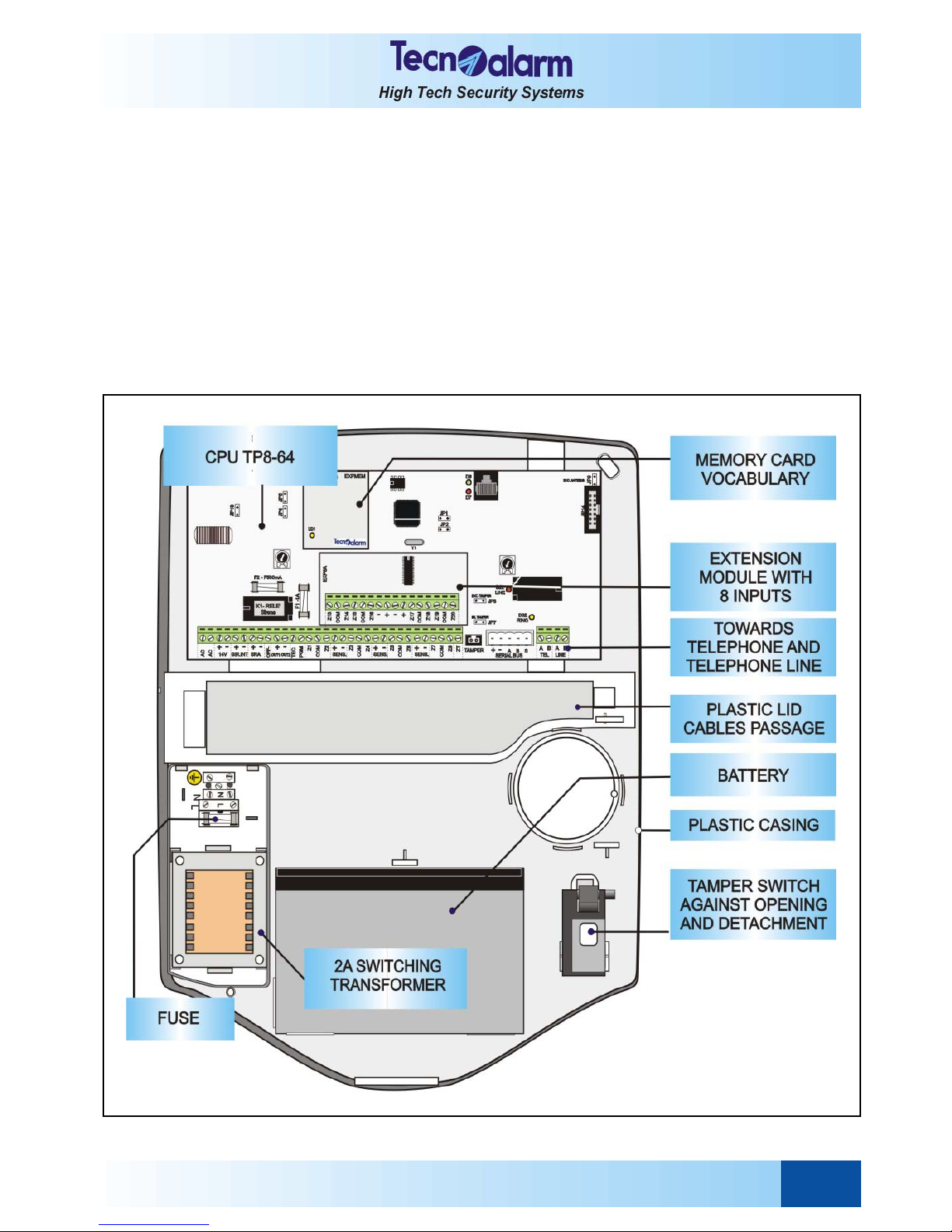
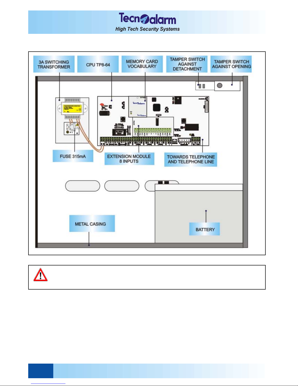
1.5 COMPOSITION OF THE CONTROL PANEL
TP8-64
General Features User Manual - TP8-64
1-4
WARNING
Do not open the control panel casing. Unauthorized opening of the casing causes a tamper alarm with
activation of the sirens. The electronic components may be under high voltage.
For maintenance, consult a qualified installe.
TP8-64 MET
TP8-64 - User Manual Signaling
2-1
2. SIGNALING
2.1 LED SIGNALING OF THE CONSOLES
The TP8-64 control panel controls up to 15 consoles:
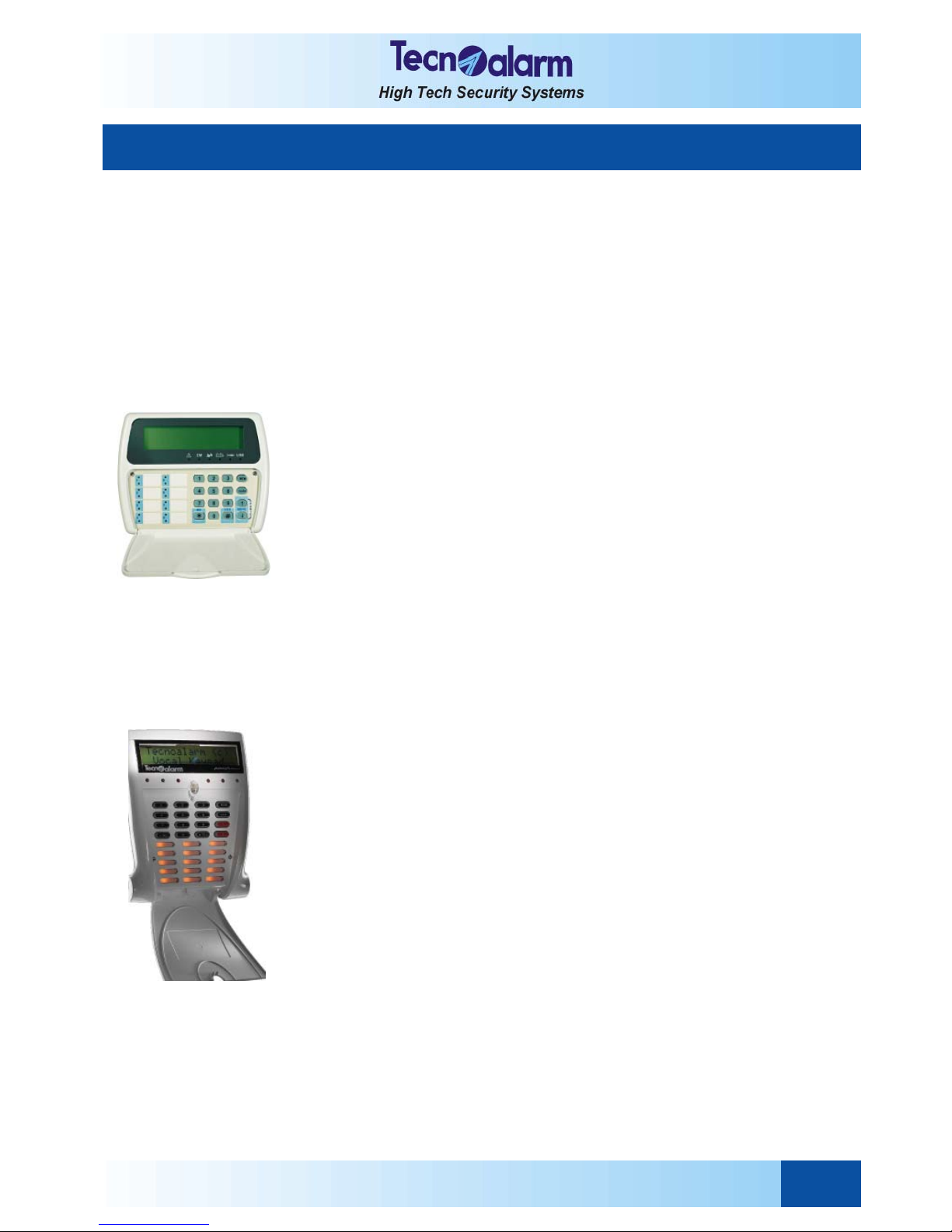
z Console with liquid crystal display (LCD) LCD200
z Console with liquid crystal display (LCD) and speaker LCD300/S, design by
The console provides coloured LED for signaling of the alarms and system status.
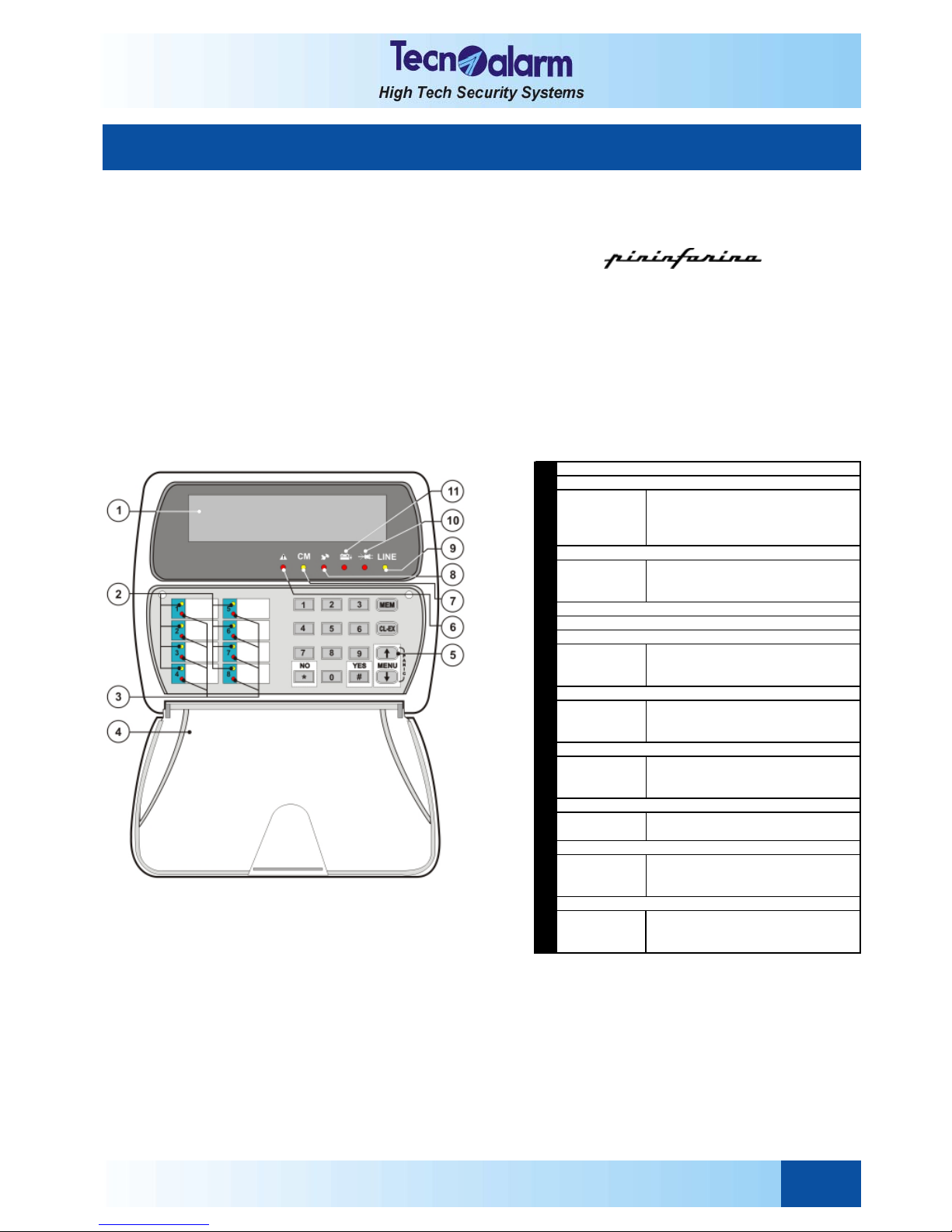
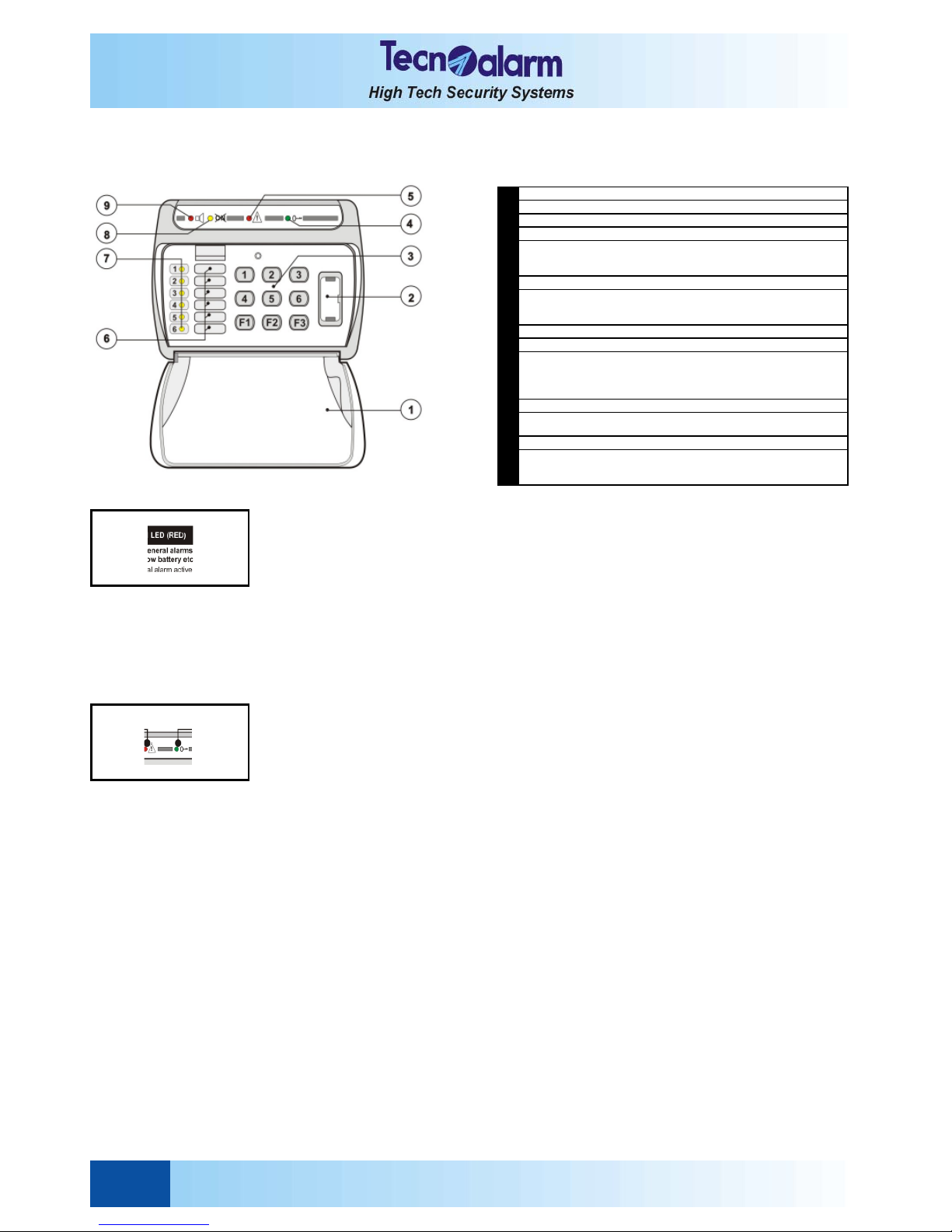
LCD200 CONSOLE
The LCD200 console is composed of:
z Rubber keypad with 16 keys
z 22 LED
z Backlit liquid crystal display (LCD) with two lines of 16 caracters each
z Blank labels for the program names
z Plastic lid
The console must be connected via RS485 serial bus to the control panel and its address must be configurate by SW1
dipswitch.
In addition it is possible to program the language of the console diagnostics by jumper.
1
Off
B link in g q uickly
B link in g slow ly
On
Program in stand-by
A rming phas e ac tiv e
Pr ogram partset
Pr ogram armed
Off
Blinking
On
No a larm
Pr ogram alarm active
A larm stored (alarm memory)
4
5
Off
Blinking
On
No a larm
General alarm active
A larm stored (alarm memory)
Off
On
No key pres s ed (cons ole in s tand-by)
Keys troke
Off
Blinking
On
No a larm
Tamper alarm active
A larm stored (alarm memory)
Off
On
Serial bus disc onnected or disturbed
Connection an d f unc tioning ok
Off
Blinking
On
No a larm
Pow e r f a ilure
A larm stored (alarm memory)
Off
Blinking
On
No a larm
Low battery
A larm stored (alarm memory)
11
BA TT ERY L ED (R ED )
9
L INE L ED ( Y EL LO W)
10
PO WER L ED (RED)
7
C O M M A ND M ODE L ED ( Y EL LO W)
8
TA M PER L ED (R ED )
6
GENERAL ALA RM L ED (RED)
KEYPA D
PROGRA M AL A RM L ED (RED)
PROTEC T ION FLA P
DISP L A Y
2
PROGRA M STA T US LED (YELLOW )
3
Signaling User Manual - TP8-64
2-2
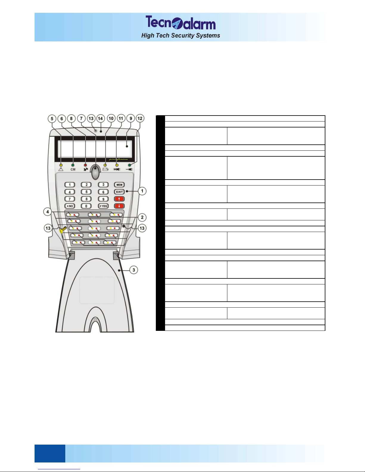
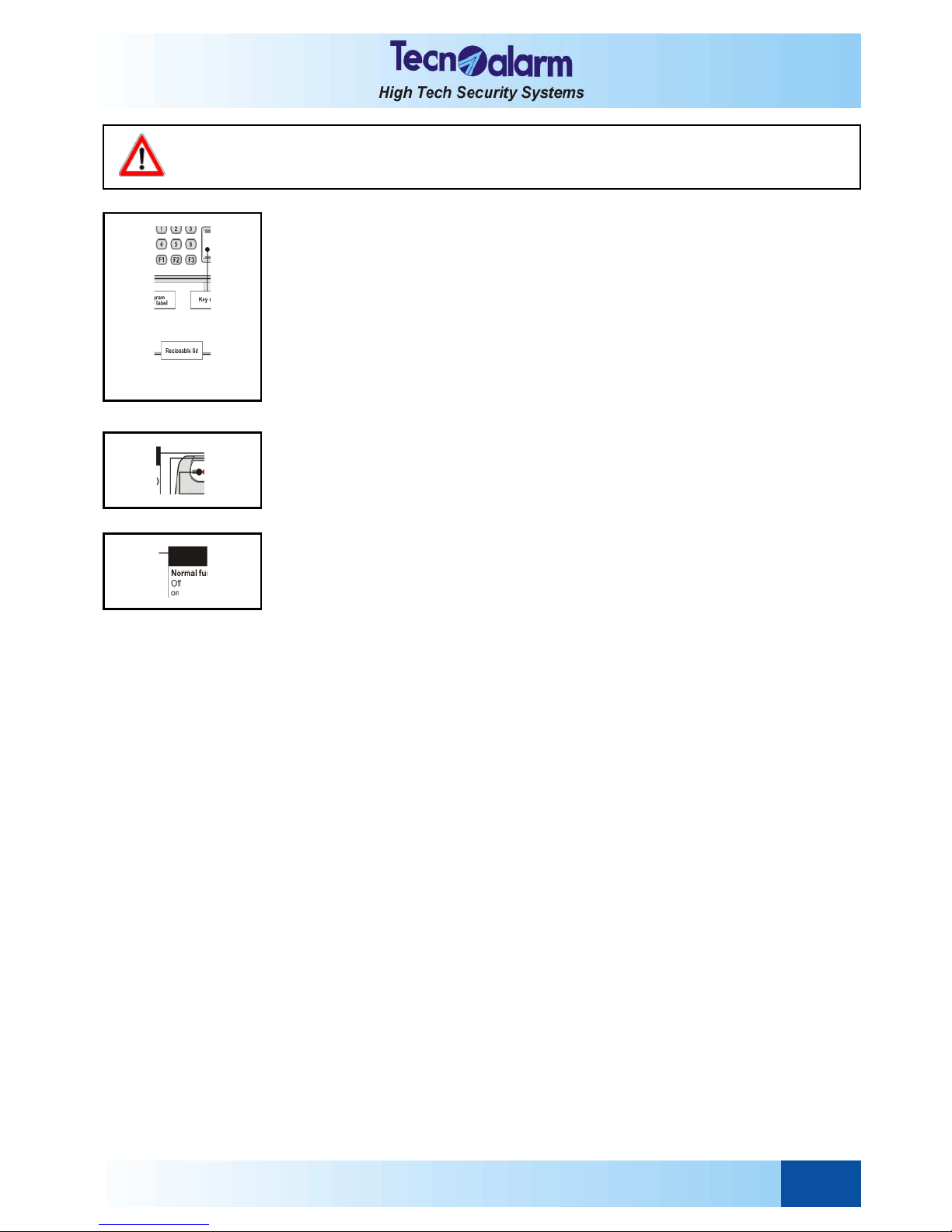
CONSOLE LCD300/S
The LCD300/S console is composed of:
z Rubber keypad with 16 keys
z 22 LED
z Backlit liquid crystal display (LCD) with two lines of 16 caracters each
z Blank labels for the program names
z Speaker for vocal messages
z Plastic lid
The console must be connected via RS485 serial bus to the control panel and its address must be configurated by
SW1dipswitch.
1
LED off
LED blinking
LED on
No alarm
Alarm ac tive
Alarm memory
3
LED off
LED blinking quickly
LED blinking slowly
LED on
Program in stand-by
Program in arming phase
Program pa rtset
Program arm ed
LED off
LED blinking
LED on
No alarm
Alarm ac tive
Alarm memory
LED off
LED on
Console in stand-by (no key pressed)
Console in use (key pressed)
7
LED off
LED blinking
LED on
No alarm
Alarm ac tive
Alarm memory
9
LED off
LED blinking
LED on
No alarm
Insufficient battery voltage
Alarm memory
LED off
LED blinking
LED on
No alarm
M a in s po w er (2 3 0V A C ) mis s in g
Alarm memory
LED off
LED on
M a in s po w er (2 3 0V A C ) mis s in g
M a in s po w er (2 3 0V A C ) o k
13
14
SCREWS
SCREW PROTECTION LID
6
DISPLAY
Sho ws da te/time or active parameter
BATTERY LED
M AINS (PO W ER F AILU RE) LED
MAINS LED
11
12
KEYP AD
PRO GRAM ALARM LED
RECLOSABLE PROTECTION LID
PRO GRAM S TATUS LED
GENERAL ALARM LED
COM M AND M ODE LED
PUSH-BUTTON OF THE PROTECTIO N LID
TAMPER ALARM LED
2
4
5
10
8
TP8-64 - User Manual Signaling
2-3
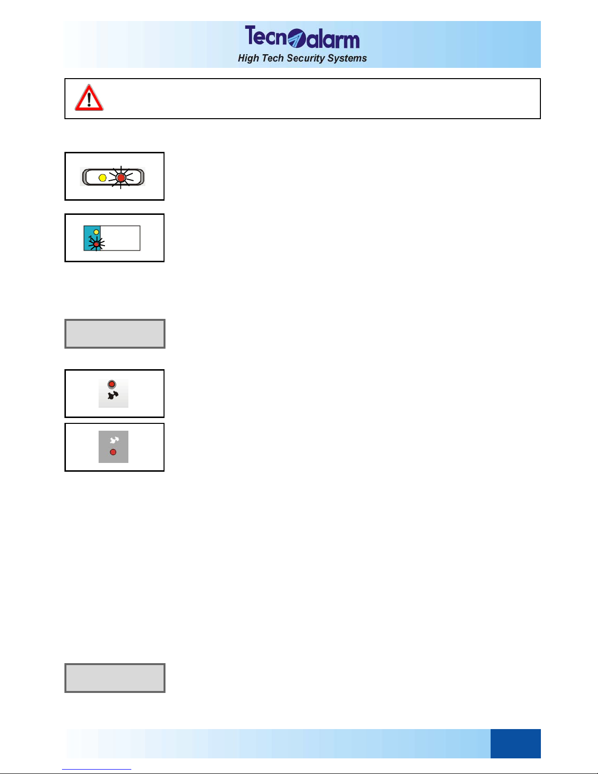
2.1.1 ALARM LED - RED
The red alarm LED signal the alarms as follows:
z LED on = the corresponding alarm has been stopped and stored in the
event buffer of the control panel (alarm memory).
z LED blinking = the corresponding alarm is active.
z LED off = no alarm has occurred.
PROGRAM ALARM LED
The red program alarm LED signal the program alarms as follows:
z LED blinking = the corresponding program is in alarm.
The LED starts blinking as soon as one of the zones grouped
by the program is opened or in alarm. It remains blinking during
the entire alarm time. On expiry of the alarm time, the alarm is
stopped and the LED remains lit.
z LED on = the corresponding program alarm has been stopped and stored
in the event buffer of the control panel (alarm memory)
The LED remains lit until the control panel is armed again.
z LED off = no alarm has occurred.
According to programming, the indoor and/or outdoor sirens are
activated for program alarm.
Signaling on display
In addition to LED signaling, program alarms are signalled on the display of the console
with indication of the zone in alarm.
TAMPER LED
The tamper alarm is a direct alarm and always enabled (even if the control panel is in
stand-by).
It is released for:
z Opening of the tamper input (ZT).
z Opening of the tamper contact of the console or of one of the modules or detectors
connected via serial line.
z Tampering of one of the zones of the system (e.g. the cables have been cut).
The zone tamper alarm is recognized merely by the double end-of-line resistor
zones.
z Short circuit on the detector connection cables
The red tamper LED signals tamper alarms as follows:
Control panel armed
z LED blinking = a tamper alarm is active.
The LED starts blinking on detection of the alarm and remains
blinking during the entire tamper alarm time.
On expiry ot the tamper alarm time, the alarm is stopped and
the LED remains lit.
z LED on = a tamper alarm has been stopped and stored in the event buffer
of the control panel (alarm memory).
If the control panel is armed, in case of tamper alarm, the
outdoor and indoor sirens are activated.
Control panel in stand-by
z LED blinking = a tamper alarm is active.
The LED starts blinking on detection of the alarm and remains
blinking during the entire tamper alarm time. On expiry ot the
tamper alarm time, the alarm is stopped and the LED remains
lit.
z LED on = a tamper alarm has been stopped and stored in the event
buffer of the control panel (alarm memory).
To find out the zone violated, view the events logged in the
buffer. If the control panel is in stand-by, in case of tamper
alarm, the indoor sirens are activated.
Signaling on display
In addition to LED signaling, tamper alarms are signalled on the display of the console
by a message indicating the kind of violation.
ALARM
Expansion Z2
TAMPER
Keypoint 1
WARNING
The hold-up alarm does not cause any LED signaling on the console. It is a silent alarm. It is, however,
stored in the event buffer.
Signaling User Manual - TP8-64
2-4
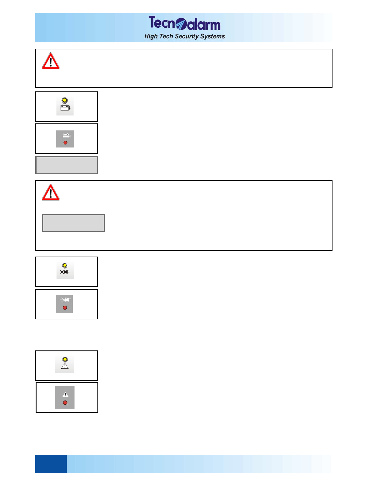
BATTERY LED
The battery LED signals low battery alarms as follows:
z LED blinking = battery voltage is inferior to 11V or voltage of the battery of the
radio devices is inferior to 2.7V.
z LED on = battery voltage has returned to accepted values and thealarm
has been stored in the event buffer of the control panel (alarm
memory).
To find out the battery of which radio device has caused the alarm, view the events
logged in the buffer.
Both events, beginning and end of low battery alarm, are logged in the event buffer of the
control panel.
Signaling on display
In addition to LED signaling, low battery alarms are signalled on the display of the
console with indication of the radio module interested, if necessary.
MAINS LED
The power failure alarm is a direct alarm and always enabled (even if the control panel is
in stand-by).
It is released as soon as mains power (230V AC) is missing, unless a delay of power
failure alarm has been programmed. The delay can be programmed in 10-minutes steps
from a minimum of 10 minutes to a maximum of 9 hours and 50 minutes. This is avoid
false alarms in case of sudden voltage drops or short-term mains disconnection for
maintenance on the electric installation.
The mains LED signals power failure alarms as follows:
z LED blinking = power failure alarm active.
z LED on = mains power has returned to accepted values and the alarm has
been stored in the event buffer of the control panel (alarm
memory).
Both events, beginning and end of power failure alarm, are logged in the event buffer of
the control panel.
GENERAL ALARM LED
The general alarms are direct alarms that are always enabled.
Among the general alarms count:
z Antimasking alarm
The radio receiver has been jammed.
z Supervision alarm
One of the radio devices has not transmitted any test signal/alarm for a period
superior to the supervision interval programmed.
z False key
An unknown key has been inserted in one of the key reader connected.
z False code
32 or more keys have been pressed on one of the consoles and keypads connected
without entering a valid code.
z GSM fault
Communication with GSM telephone communicator lost, SIM card missing.
LOW BATTERY
Ctrl panel
WARNING
In case of tamper alarm, arming is denied and is displayed ! Arming denied !, unless the code used
for arming has be enabled for the by-pass of general alarms (see programming). To re-establish normal
functioning conditions, eliminate the reason for alarm.
Tamper alarm memory signaling cannot be cancelled by the user, address your installer.
WARNING
If while mains power is missing, the voltage of the battery drops below the minimum
value guaranteeing correct functioning of the control panel (inferior to 9V), the battery
is automatically disconnected in order to protect it from final and irreversible
discharge.
In this case, the system loses all date/time settings as, merely system status and
alarm memory signaling in maintained.
On return of battery voltage or battery replacement, the displays of the consoles
show the date and time with an invalid month field. All date/time settings must be
programmed again, otherwise the scheduled functions such as automatic arming and
test call will remain disabled.
Fri 01 --- 00
Work. 00:01
TP8-64 - User Manual Signaling
2-5
z Cut telephone line
Signaling on display
In case of GSM fault and cut telephone line alarm, in addition to LED signaling, on the
display is viewed a specific alarm message.
z LED blinking = general alarm active.
z LED on = a general alarm has been stored in the event buffer of the
control panel (alarm memory).
2.1.2 CONTROL LED - YELLOW
PROGRAM STATUS LED
The yellow program LED signal program status:
z LED blinking quickly = the pre-arming phase is active (10s after selecting the
programs to be armed).
The pre-arming phase permits arming/disarming of other
programs. Then, the volontary exclusion of zones from
the detection of alarms is possible.
z LED blinking slowly = the program is partset.
The zones included in the by-pass program are
temporarily disabled from the detection of alarms.
z LED on = the program is armed
z LED off = the program is in stand-by
Arming and disarming as well as the activation and deactivation of by-pass are logged in
the event buffer of the control panel.
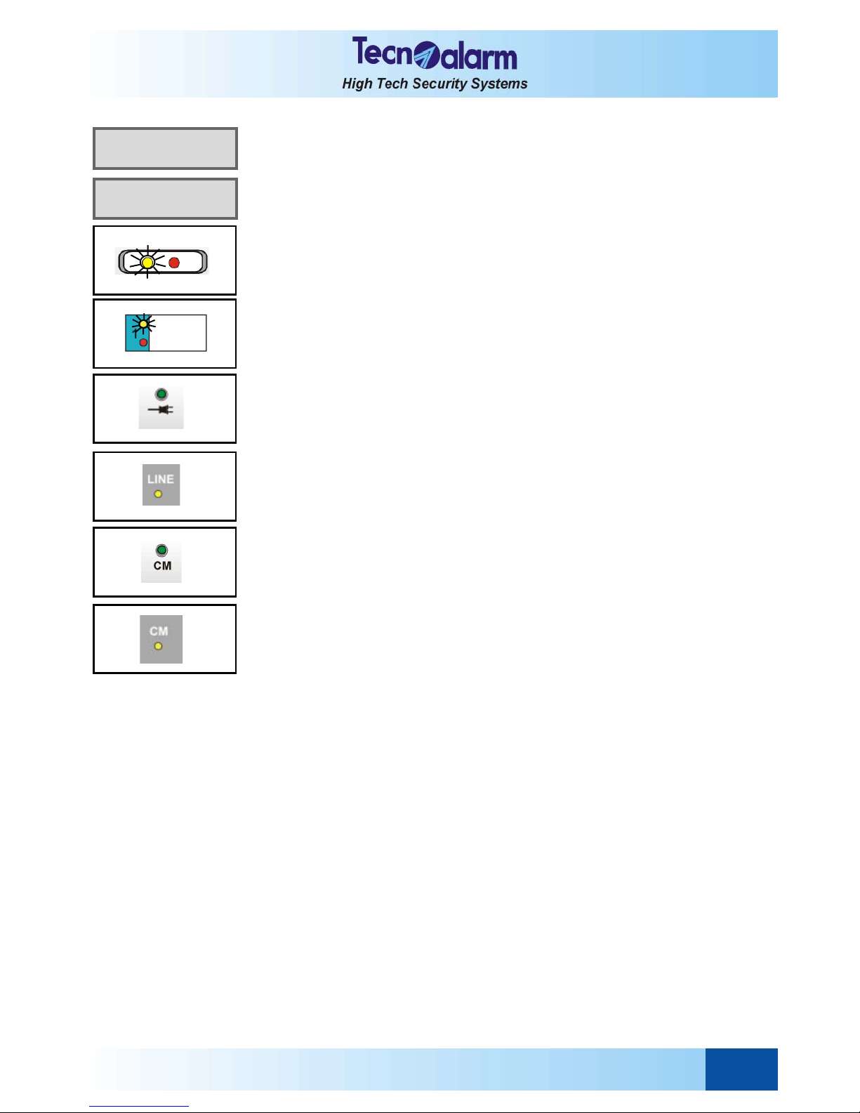
LINE LED 0
The LINE LED signals the status of the console connection:
z LED on = the console is connected and works correctly
z LED off = the serial line is disturbed or badly connected.
CONSOLE STATUS LED CM
The console status LED CM signals the status of the console:
z LED on = keystroke
z LED off = the serial line is disturbed or badly connected.
! TROUBLE !
CUT TEL. LINE
! TROUBLE !
Mobile
Signaling User Manual - TP8-64
2-6
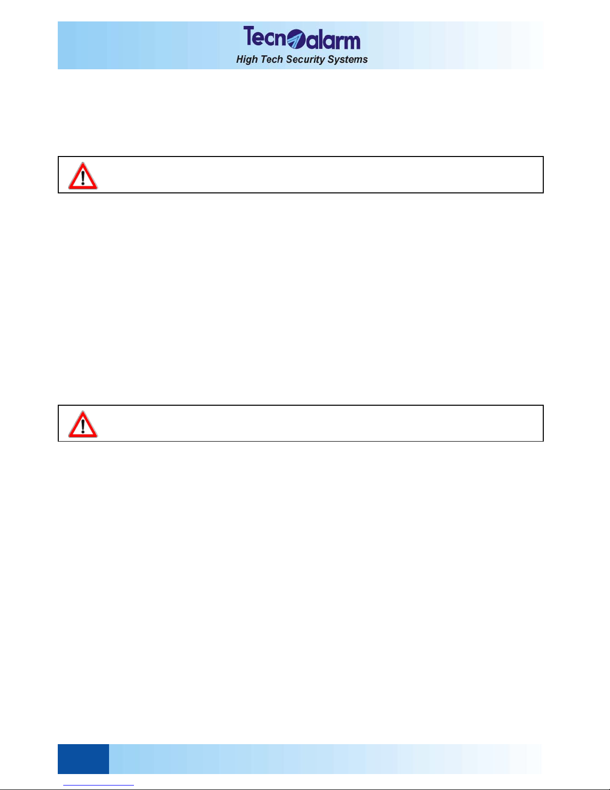
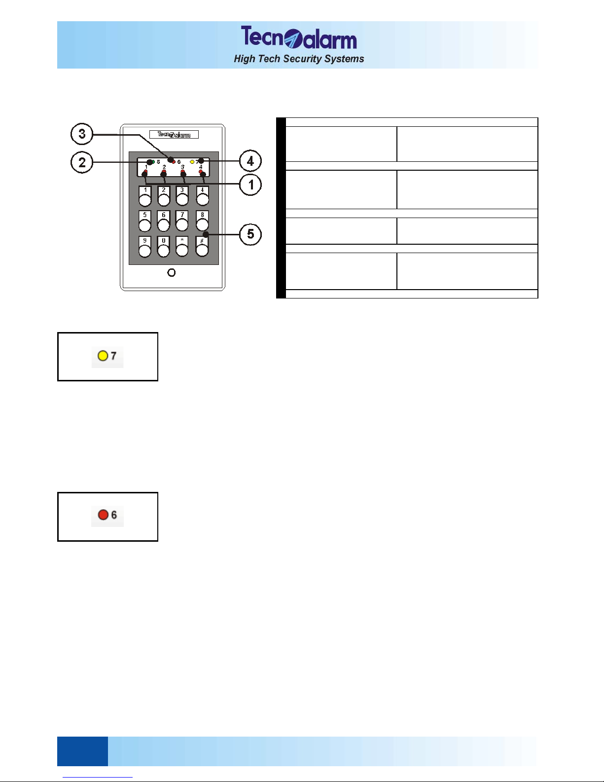
2.2 LED SIGNALING OF THE TP SDN ELECTRONIC KEYPAD
The electronic keypad provides coloured LED for signaling of the alarms and system status.
2.2.1 PROGRAM ALARM LED - YELLOW
The program alarm is detected only if the control panel is armed.
The yellow program alarm LED signal program alarms as follows:
z LED blinking = a program alarm is active.
The LED starts blinking as soon as one of the zones of the
program is opened or in alarm and remains blinking for the
entire alarm time. On expiry of the alarm time, the alarm is
stopped and the LED becomes lit.
z LED on = a program alarm has been stopped and stored in the event
buffer (alarm memory).
The LED remains lit until the control panel is armed again.
z LED off = no alarm has occurred.
The program alarm is logged in the event buffer of the control panel.
According to programming, the indoor and/or outdoor sirens as well as the logic output
PGM are activated for program alarm.
2.2.2 GENERAL ALARM LED - RED
The general alarm is a direct alarm that is always enabled.
Among the general alarms count:
z Antimasking alarm
The radio receiver has been jammed.
z Supervision alarm
One of the radio devices has not transmitted any test signal/alarm for a period
superior to the supervision interval programmed.
z False key
An unknown key has been inserted in one of the keypoint connected.
z False code
32 or more keys have been pressed on one of the consoles and keypads connected
without entering a valid code.
z GSM fault
The mobile phone does not answer to the interrogations by the GSM interface
TECNOCELL for a period of approximately 10s.
z Cut telephone line
The telephone line voltage is missing for a period of approximately 1 minute.
z Low battery
The battery voltage has fallen to a value below the minimum guaranteeing correct
functioning of the control panel (<11V) or voltage of the battery of one of the radio
devices connected is insufficient (<2.7V).
z Power failure (230V AC)
LED off
LED blinking quickly
LED blinking slowly
LED on
Program in s tand-by
Program in pre-arming phase active
Program partset
Program arm ed
LED off
LED blinking quickly
1 flash
LED on
Key pad in stand-by
Another key pad in use
Keystroke
Key pad ac tive (valid code)
LED off
LED blinking
LED on
No alarm
Alarm ac tive
Alarm s tored (alarm m em ory)
LED off
LED blinking quickly
LED blinking slowly
LED on
No alarm
Direct open zones on arming
Alarm ac tive
Alarm s tored (alarm m em ory)
5
KEYPAD
4
GENERAL CONTROL L ED (O CG)
GENERAL ALARM LED
3
COM M AND MO DE LED
STATUS P ROGRAM LED (1...4)
1
2
TP8-64 - User Manual Signaling
2-7
The general alarm LED signals general alarms as follows:
z LED blinking = a general alarm is active
z LED on = a general alarm has been stopped and stored in the event
buffer of the control panel (alarm memory).
z LED off = no alarm has occurred
The general alarms are logged in the event buffer of the control panel.
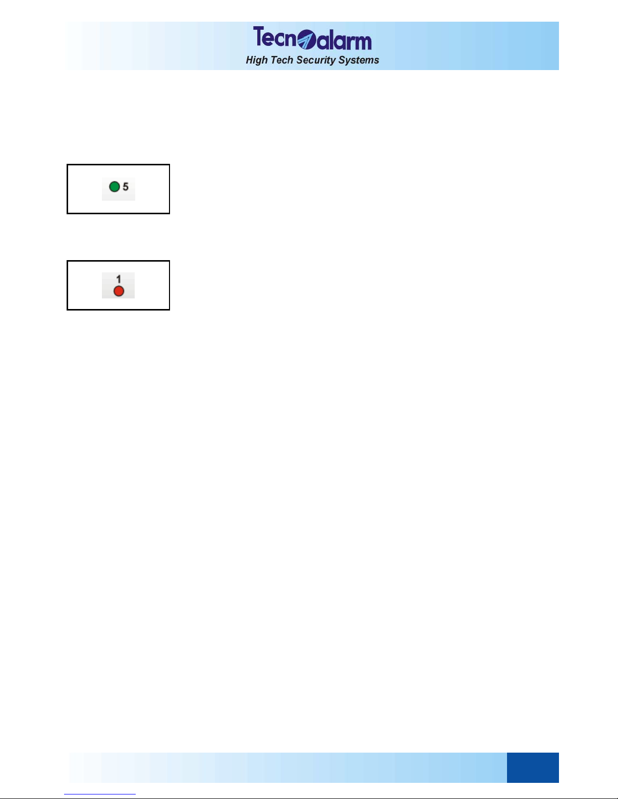
2.2.3 KEYPAD STATUS LED - GREEN
The green keypad status LED signals the status of the electronic keypad:
z LED on = a valid code has been entered (master or standard user
code)
z LED off = the keypad is in stand-by
z LED blink.quickly = someone is arming the system through another console/
electronic keypad
z 1 flash = keystroke
2.2.4 PROGRAM STATUS LED - RED
The red program status LEDs signal the status of the first 4 programs (1...4) as follows:
z LED blink. quickly = the pre-arming phase is active.
The pre-arming phase permits arming/disarming of other
programs. Then, the volontary exclusion of zones from the
detection of alarms is possible.
z LED blink. slowly = the program is partset.
The zones included in the by-pass program are temporarily
disabled from the detection of alarms.
z LED on = the program is armed
z LED off = the program is in stand-by
Arming and disarming as well as the activation and deactivation of by-pass are logged in
the event buffer of the control panel.
Signaling User Manual - TP8-64
2-8
2. 3 LED SIGNALING OF THE TP SK6N KEY READER WITH MINI KEYPAD
The TP SK6N key reader with mini keypad provides coloured LED for signaling of the alarms and system status.
2.3.1 PROGRAM ALARM LED - RED
The program alarm LED signals the program alarms as follows:
z LED blinking = a progarm alarm is active.
The LED starts blinking as soon as one of the zones of the
program is opened or in alarm and remains blinking for the
entire alarm time. On expiry of the alarm time, the alarm is
stopped and the LED becomes lit.
z LED on = a program alarm has been stopped and stored in the event
buffer of the control panel (alarm memory). The LED remains lit
until the control panel is armed again.
z LED off = no alarm has occurred
The program alarms are logged in the event buffer of the control panel.
2.3.2 GENERAL ALARM LED - RED
The general alarm is a direct alarm that is always enabled.
The general alarm LED signals general alarms as follows:
z LED blinking = a general alarm is active
z LED on = a general alarm has been stopped and stored in the event
buffer of the control panel (alarm memory)
z LED off = no alarm has occurred
The general alarms are logged in the event buffer of the control panel.
Among the general alarms count:
z Antimasking alarm
The radio receiver has been jammed.
z Supervision alarm
One of the radio devices has not transmitted any test signal/alarm for a period
superior to the supervision interval programmed.
z False key
An unknown key has been inserted in one of the keypoint connected.
z False code
32 or more keys have been pressed on one of the consoles and keypads
connected without entering a valid code.
z GSM fault
The mobile phone does not answer to the interrogations by the GSM interface
TECNOCELL for a period of approximately 10s.
z Cut telephone line
The telephone line voltage is missing for a period of approximately 1 minute.
z Low battery
The battery voltage has fallen to a value below the minimum guaranteeing correct
functioning of the control panel (<11V) or voltage of the battery of one of the radio
devices connected is insufficient (<2.7V)
z Power failure (230V AC)
1
PLAS TIC LID
2
KEYP O INT
3
KEYP AD
KEYPAD LED (GREEN)
LED of f : no key inserted
LED blinking : key ins erted in another key point or fals e key
LED on : key rec ognized
GENERAL ALARM LED (RED)
LED off : no alarm
LED blinking : A larm a ctive
LED on : alarm memory
6
BLANK LABELS FOR P RO GRAM NAMES
PRO GRAM S TATUS LED (YELLO W )
LED off : program in stand-by
LED blinking quickly : pre-arming phase active
LED blinking slow ly : program partset
LED on : program armed
ZONE STATUS LED (YELLOW )
LED off : all z ones OK
LED blinking quickly :open zone on arming
PRO GRAM ALARM LED (RED)
LED off : no alarm
LED blinking : one or more programs in alarm
LED on : alarm memory
9
4
5
7
8
TP8-64 - User Manual Signaling
2-9
2.3.3 PROGRAM STATUS LED - YELLOW
The program status LED signal the status of the first 6 programs (1...6) as follows:
z LED blinking quickly = the pre-arming phase is active.
The pre-arming phase permits arming/disarming of other
programs. Then, the volontary exclusion of zones from
the detection of alarms is possible.
z LED blinking slowly = the program is partset
The zones included in the by-pass program are
temporarily disabled from the detection of alarms.
z LED on = the program is armed
z LED off = the program is in stand-by
Arming and disarming as well as the activation and deactivation of by-pass are logged in
the event buffer of the control panel.
2.3.4 ZONE STATUS LED - YELLOW
The zone status LED signals zone status during arming:
z LED blinking = one of the zones is open
z LED off = none of the zones is open
2.3.5 KEY LED - GREEN
The key LED signals:
z LED on = the key has been recognized
z LED off = no key has been inserted
z LED blinking = a key has been inserted into another keypoint or, if
contemporaneously the red general alarm LED is lit,
an unknown key has been inserted
WARNING
If a general alarm is active, arming by key is denied.
 Loading...