

TECNICCAT MAMNET ECO 20, MAMNET ECO 30, MAMNET ECO 15, MAMNET ECO 45 User Manual
MANUAL
MAMNET ECO 15 / 20 / 30 / 45
1
Dear Customer,
Thank you for choosing a MAMNET ECO SALT ELECTROLYSIS system for your swim-
ming pool.
MAMNET ECO SALT ELECTROLYSIS SYSTEMS have been designed and manufac-
tured for the specific requirements of the water in your swimming pool. Its simple management, easy installation and low maintenance ensure that you will almost never have to
worry about it.
Before beginning installation, read carefully this instructions manual and once the system
has been started, keep it in a safe place for future reference.
The instructions in this manual describe the operation of the models Mamnet Eco 15,
Mamnet Eco 20, Mamnet Eco 30, Mamnet Eco 45, ORP and pH.
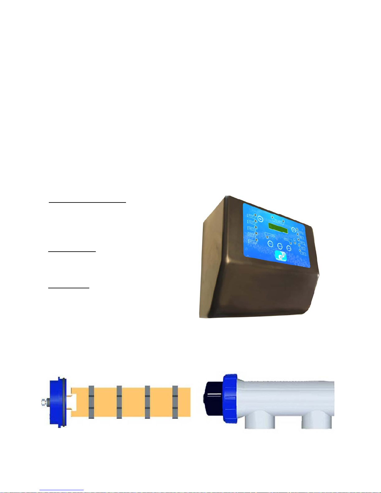
C HECK elements supplied:
Central Processing Unit (CPU)
Electrode
Electrode holder
Manual
Optional ORP:
1 ORP Probe.
1 Probe holder.
1 Buffer solution 465mV
Optional pH:
1 pH Probe
1 Probe holder
1 Peristaltic pump
1 Buffer solution pH4
1 Buffer solution pH7

2
VERY IMPORTANT
Before installation or carrying out any maintenance task, disconnect the power cable from the
CPU (230 Vac).
The system must be installed by qualified people, in accordance with all local and national
electrical regulations.
Check that the power supply voltage corresponds to which is indicated on the label located on
the side.
Be sure the electrical connections are firm in order to avoid false contacts, resulting in
over-heating.
Do not connect the network power supply cable before having made all power supply
connections to the electrolysis cell.
Choose an installation site where the system will be easy to access and enable easy viewing
of the CPU and the electrode.
TECHNICAL SPECIFICATIONS:
DIMENSIONS:
CPU SPECIFICATIONS:
CONTROL MICROPROCESSOR
POWER SUPPLY 230 V ac/50-60Hz/H50RR-F-3G (3 x 1 mm
2
)
OUTPUT 7,5V dc, 15A (MamNet Eco 15) / 6,8V dc 20A (MamNet
Eco 20) / 6,3V dc 30A (MamNet Eco30) / 7V dc 45A
(Mamnet Eco 45) max.
RV-K-1000V 2x6mm² cable electrodo
CABLE FOR TEMPERATURE +
WATER DETECTOR
3x1 mm
2
H05VV-F-3G1
SELF-CLEANING AUTOMATIC PROGRAMMABLE POLARITY CHANGE
FUSIBLE 2A (MAMNET ECO 15, 20) / 3,15A (MAMNET ECO30, 45)
REFRIGERATION CONVECTION/FORCED
3
ELECTRODE SPECIFICATIONS:
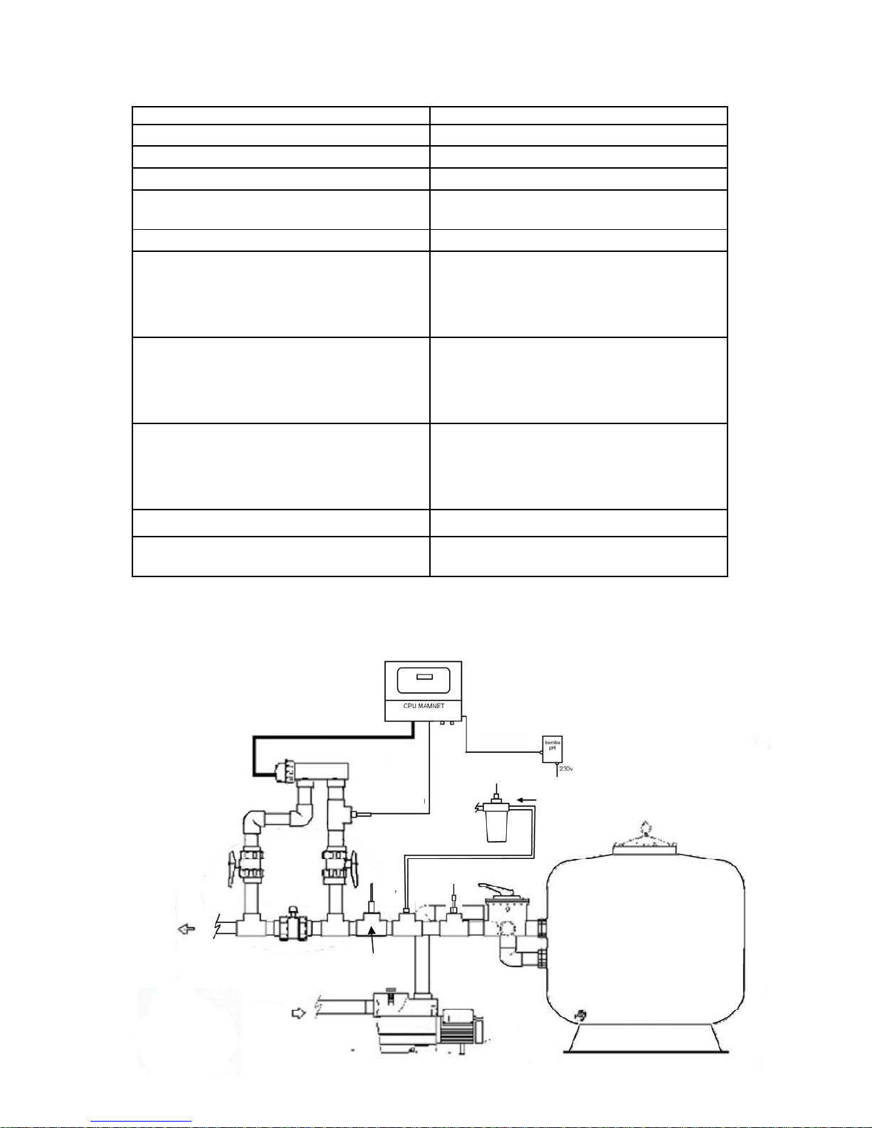
HOW TO INSTALL: Recommended installation diagram:
RECOMMENDED SALINITY 4.5 gr NACI / Litre
SALINITY RANGE 4-6 gr/L
ELECTRODE TITANIUM WITH SPECIAL OXIDES
MAXIMUM PRESSURE 1,5 kg/cm
2
ELECTRODE HOLDER POLYMER FROM THE METHACRYLATE
FAMILY
CONNECTION TO PIPEWORK GLUED WITH PVC ADHESIVE / Æ 63
NaCIO PRODUCTION (25ºC 4,5 gr/L NaCl) 15g/h 360gr/day
20gr/h 480gr/day,
30g/h 720gr/day
45g//h 1080gr/day
MINIMUM FLOW RECOMMENDED 7,5
3
/mh ECO15, 11,53/mh ECO20,
16
3
/mh ECO30, 203/mh ECO45
No OF PLATES PER ELECTRODE 10+ MAMNET ECO 45 FLOW DETECTOR
6+ MAMNET ECO 30 FLOW DETECTOR
4+MAMNET ECO 20 FLOW DETECTOR
4 SHORT + MAMNET 15 FLOW DETECTOR
TEMPERATURE DETECTOR SEMI-CONDUCTOR
LOAD LOSS
0,15 Kgr/cm2 < 20 m3/h
CPU ABOVE THE ELECTRODE
PUMP pH
PROBE ORP
INJECTOR pH
PROBE pH
SWITCH FLOW
STOP2

4
Always install the MAMNET ECO system CPU vertically and on a rigid surface (wall).
To guarantee a good state of conservation, the equipment must always be stored in a dry and
well-ventilated place. Given the level of water-tightness of the MAMNET system's CPU,
do not install during bad weather.
The CPU must be installed sufficiently far away from the electrode holder so that it is not
subject to accidental water splashes. It must also be installed above the CPU.
Be especially careful to avoid corrosive environments due to minimised pH
solutions (particularly those made with hydrochloric acid "HCI", also known
commercially as "muriatic acid" or "spirits of salt").
It is recommended to use minimised pH (pH minus) based on diluted sulphur to avoid
corrosive environments in the technical area.
The CPUs “STOP2” contact must be connected to a potential-free contact in the in
the purifier's control panel, so that the pump and the MAMNET system are
connected simultaneously. If the pump stops for an y reason, the CPU will also
stop.
ELECTRODE HOLDER:
The electrode holder is made of a transparent polymer which contains the el e c tro d e .
En su r e t h e e le c tr od e ho ld e r i s in a p l ac e t h at is p ro t ec te d fr om bad weather and always
behind the filtration system. If there are other devices in the facility such as heat pumps, control systems, etc., these must always be put into place before the electrolysis system.
The installation must allow the user to easily access the electrode.
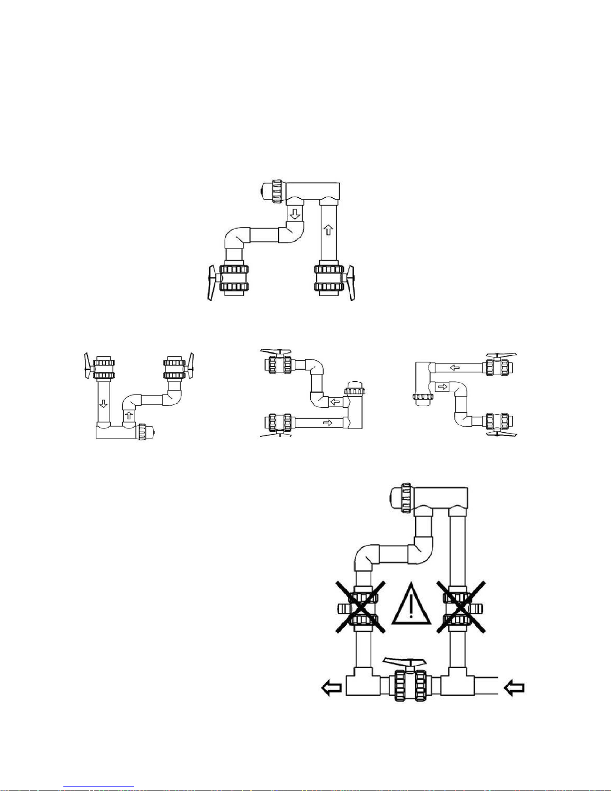
The electrode holder must always be placed HORIZONTALLY in a place in the pipes so that it
is separate from the rest of the installation by two valves. This ensures maintenance tasks can
be carried out with no need to totally or partially empty the swimming pool.
CPU:
5
If the electrode holder is installed in bypass (recommended option) i n se r t a v a lv e t h at
regulates the flow.
Th e f o l l o w i n g n o t e s m u s t b e t a ken i n t o c o n s i d e r a t i o n b e f o r e d e f i n i t i v el y installing the system:
Flow direction must be respected (input / output).
The re-circulation system must guarantee the minimum flow indicated in the technical
SPECIFICATIONS TABLE for each model.
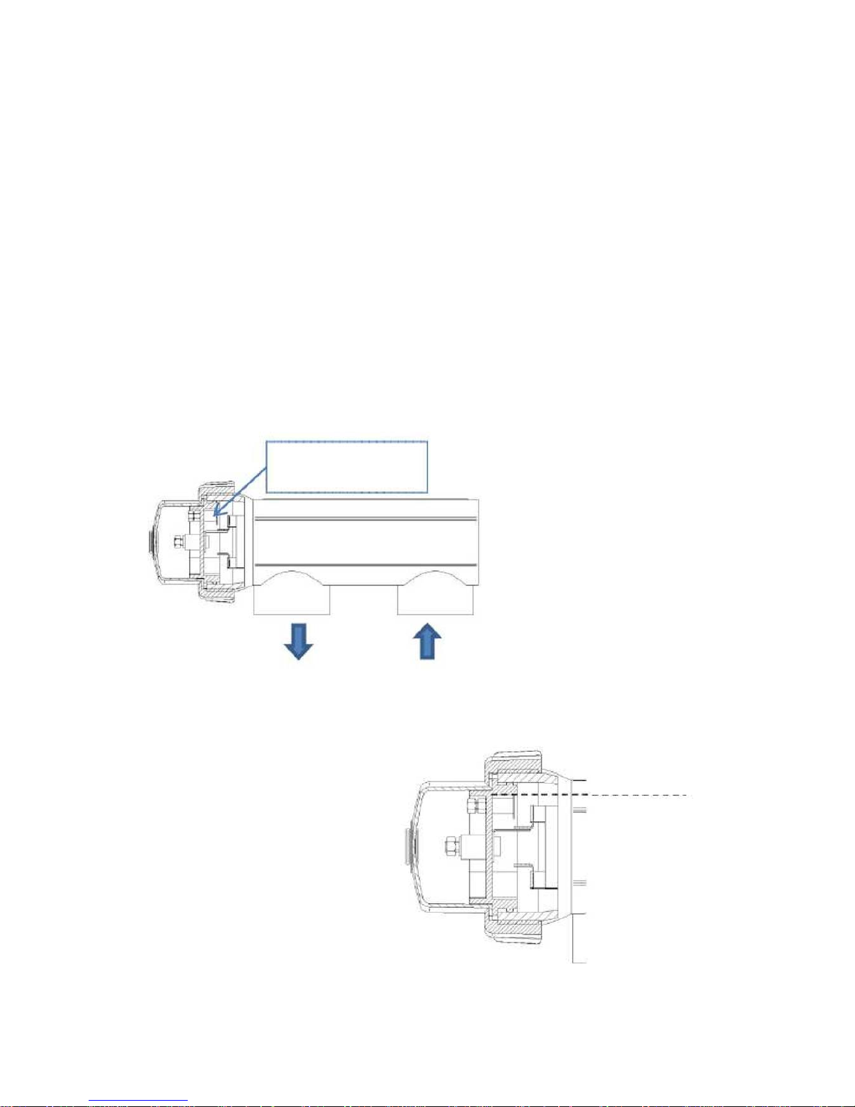
The float detector system is activated if there is no re-circulation (water flow through the cell,
or if that one is very low). If the electrolysis gas is not evacuated, a pouch will be
generated that electronically isolates it from the auxiliary electrode. Thus, when the
electrode is inserted into the electrode holder, the level probe (auxiliary electrode) must
be located on the upper part of the electrode older. The sa fest arrange ment is
indic a t e d i n t h e r e c o m m e nd e d i ns t a l l a t i o n d i a g r am (page 3).
Auxiliary electrode.
(Flow detection)
Output Input
Water level
6
METHODS FOR INSTALLING THE ELECTRODE HOLDER:
Other arrangements are only acceptable if they also enable low flow to be detected. Installations
according to the “not acceptable” configuration must be avoided, since it will not be possible
to detect "No Flow" or a large gas bubble may form.
CORRECT:
NOT ACCEPTABLE:
WARNING:
If the input and output valves to the pipe
where the electrode holder is installed are
closed simultaneously, the flow detector
will not work correctly, with a risk of
rupture resulting. Although it is an
extremely unusual situation that can be
avoided by blocking, once the
equipment is installed, the return valve
to the swimming pool, so that it cannot
be manipulated accidentally .
7
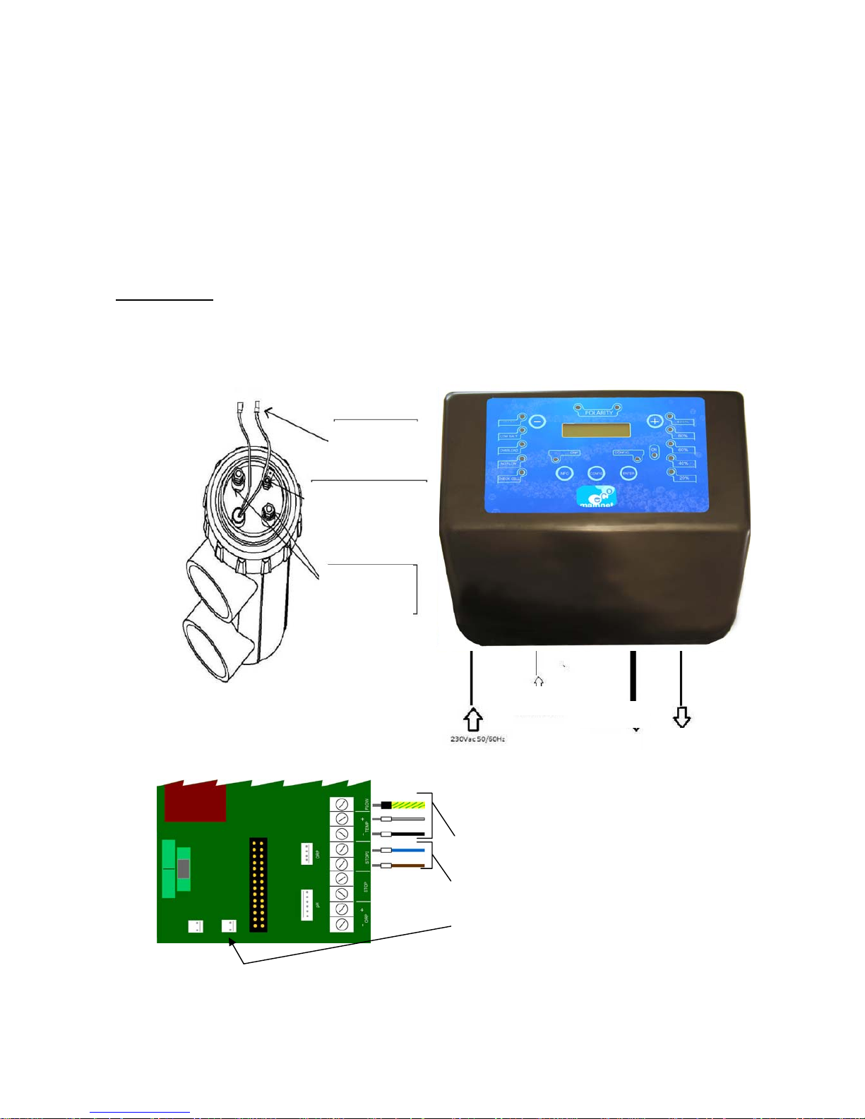
ELECTRICAL CONNECTION:
Check that all connections are firm in order to avoid false contacts, which results in over-heating.
Connect the electrode and the CPU according to the diagram on this page.
The system changes the electrodes' polarity automatically, depending on the
programming, resulting in the self-cleaning effect (anodic calcification). When
"Contact 1" is cathode "Contact 2" is anode and vice versa.
IMPORTANT: Due to the relatively high continual current intensity that circulates the electrode
power supply cables, their lengths and sections must not be modified without first consulting the
authorised distributor.
The CPU - ELECTRODE, connection cable must be from the recommended section in this
manual.
Temperature
probe
Auxiliary
electrode
Electrode
contacts
ON/OFF
ELECTRODE
FLOW DETECTOR
RELAY PLATE:
Electrode cables
Contact free power (pág.16)
In MAMNET 45 connect here the fan
8
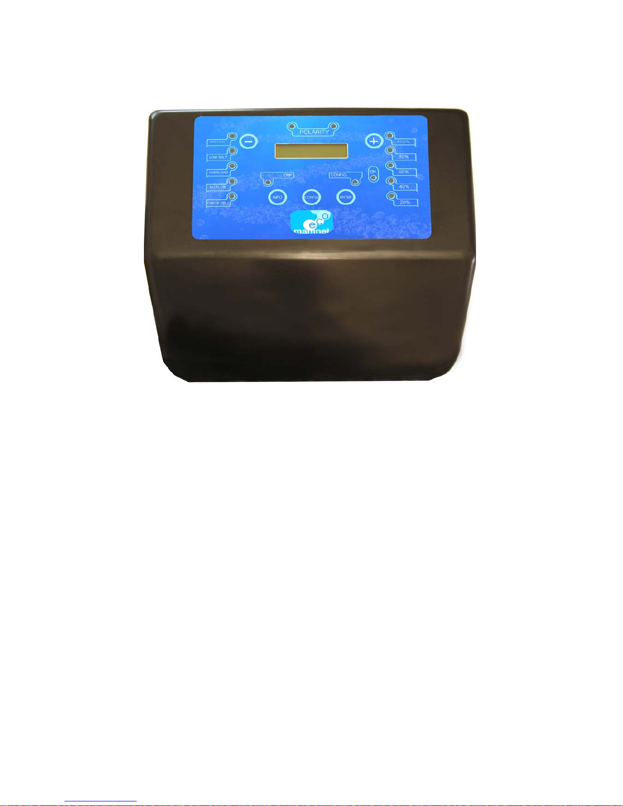
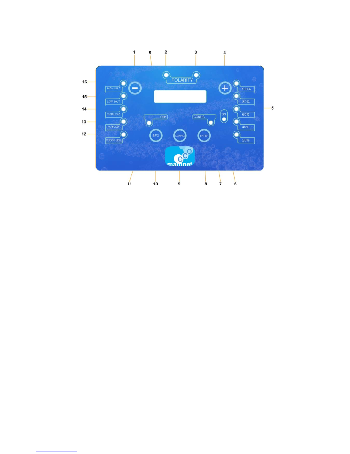
MAMNET ECO FUNCTIONS:
1.
Button to reduce chlorine production and move
around the menu.
2.
LED that indicates the equipment is operat-
ing in
direct current.
3
. LED that indicates the equipment is operat-
ing in reverse current.
4
. Button to reduce chlorine production and move
around the menu.
5
. LEDs to indicate the approx. power being used by
the CPU.
6
. LED to indicate there is voltage.
7
. LED to indicate the equipment is in configu-
ration mode.
8
. Button to execute commands and move
around the menu.
9.
Button to configure the system and move
around the menu.
10.
Button
for MAMNET ECO information and to
move around the menu.
11. LED to indicate whether the ORP function is
connected or not.
12. LED to indicate tha t th e electrode needs to
be checked.
13. LED to indicate lack of water in the
electrode holder.
14. LED to indicate an over-consumption in the
MAMNET system.
15. LED to indicate a low salt level.
16. LED to indicate a high salt level.
0.
SCREEN THAT SHOWS THE INDICATIONS AS WELL AS FAULTS AND STATUS

9
MENU CONFIGURATION:
The screen usually shows the production programmed on the upper line and the system status
on the lower line. There are two menus; the INFO information menu and the CONFIG
configuration menu.
LANGUAGE screen: Pressing CONFIG shows the language selected at this time. The
language can be changed using the +/- buttons and searching for another: (English, Spanish,
Catalonian, French, Flanders, Italian and Russian*). Whether the langua ge is cha nged or
not, pressing CONFIG passes to the next screen and pressing ENTER returns to the start
screen.
ORP screen: Shows the current selection. The +/- buttons are used to change the current
option (- = No) (+=Yes). If “No” is selected, the pH screen will appear. If the opti on is
YES, by + / - we can choose how we want it to work: 4-20mA, 0-10V, NC contact, NO
contact, FIX or ORP (for ORP see page 24). Once selected, by pressing CONFIG we
then pass to the next screen and by pressing ENTER we return to the home screen.
Screen pH: If we choose "NO" then the screen goes to the CLEANING HOURS. If the
option is YES we then open the pH menu (see page 26).
CLEANING HOURS screen: Shows the current selection, if the selection is changed by
pressing CONFIG, the SEAWATER screen will appear. Use the +/- buttons to change
the current option ( n o cleaning or every 3h, 4h up to 8h). The hours selected are those that
will change the polarity. The higher the calcium content in the water, the less time will
pass between changes in polarity! Once the time has been selected by pressing CONFIG,
the next screen will appear and pressing ENTER will return to the start screen.
SEA WATER screen: Shows the current selection. If the selection is not changed, pr essing
CONFIG will go to the ELECTRODE HOURS USE screen. Use the +/- buttons to change
the current option (Yes / No). Press ENTER to return to th e st ar t sc r ee n .
ELECTRODE HOURS USE screen: shows the total and partial hours of operation: Pressing
CONFIG goes to the next screen SET TO ZERO and pressing ENTER returns to the start
screen.
SET TO ZERO screen: Use the + / - buttons to set the partial hours counter to zero. The total will
not change. When the CHECK CELL LED is illuminated, requesting to check the electrode ,
and once it has been checked, go to this screen and set the partial to zero, which will turn off the
LED. If do not set to zero (No -) is selected, the system will return to the start menu. If yes
(Yes + ) is sel ect ed, the set to zero screen will be displayed and the system will return to the
start screen.
H HOW TO MOVE AROUND THE MENUS:
 Loading...