

Page 1
Page 2

Thank you for your purchase. We are confident that the function and
quality will bring you stable, reliable, and clear communication. Please
read this manual before operating the radio.
Welcome
Page 3
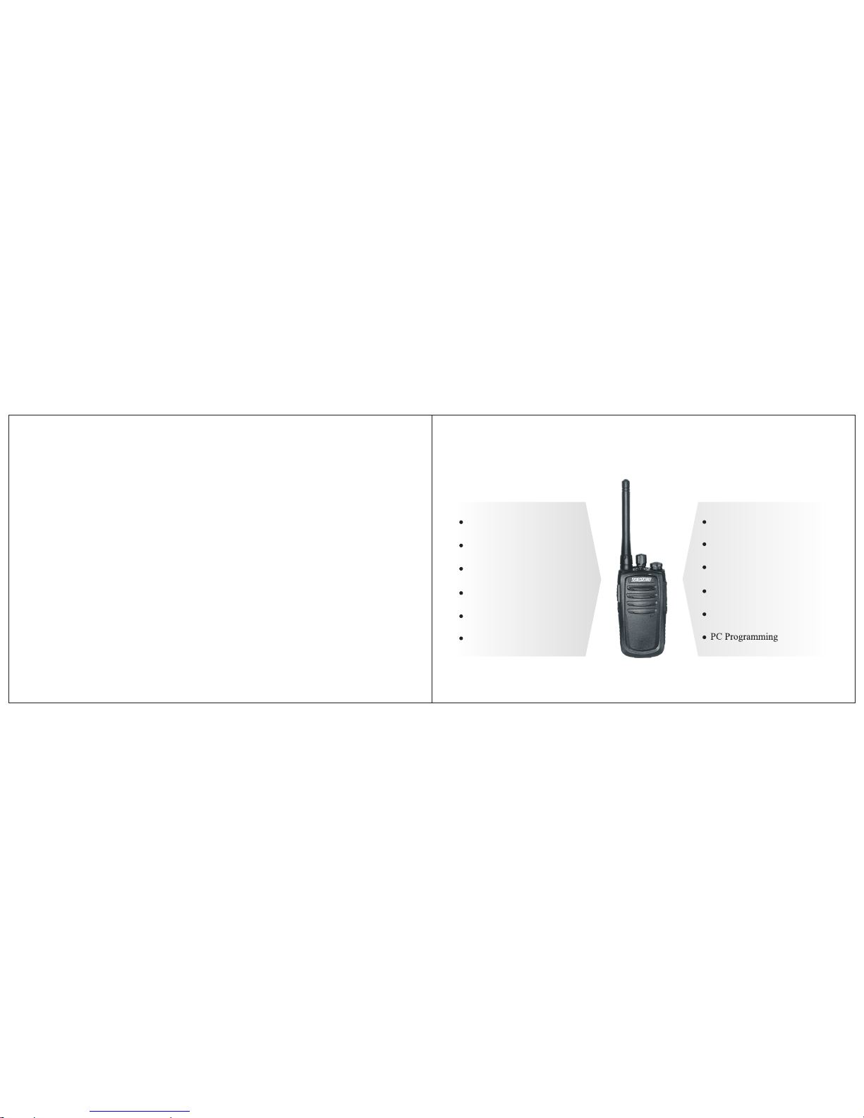
Ergonomic & Light Design
CTCSS/DCS
16 Channels
Auto Battery Save
Scan
LED Indicator Light
Voice Prompts
VOX
Programmable Key
Time-out-Timer
TS-2116/TS-2416
Wired Cloning
Page 4

01 02
Safety Information
Product Inspection
Getting Started
Attaching & Removing
Radio Overview
Basic Operation
Advanced Operation
Monitor
Battery Power Check
CTCSS & DCS
Busy Channel Lockout
DTMF Encode
Table of Contents
Table of Contents
Voice Prompts
TOT
Squelch
VOX
Scan
Low Power Alert
Battery Saving
Wired Clone
Optional Accessories
Trouble Shooting
Care and Maintenance
Warranty Statement
Table of Contents
Appendix I: Specification
Appendix II: Technical Terms
Appdendix III: Frequency & Tone
Chart TS-2116 (VHF)
Appdendix IV: Frequency & Tone
Chart TS-2416 (UHF)
03
05
06
07
09
11
13
14
14
14
14
14
15
15
15
15
15
16
16
17
18
19
20
21
22
23
25
26
…………………….……………
……………….……………
……………….……………
………….……………
…………………….……………
…………………….……………
……………….……………
……………………………….……………
……….……………
…………………….……………
………….……………
…………………….……………
…………………….……………
………………………………….……………
…………………………….……………
………………………………….……………
………………………………….……………
………………….……………
…………………….……………
……………………….……………
…………….……………
……………….……………
………….……………
…………….……………
Page 5
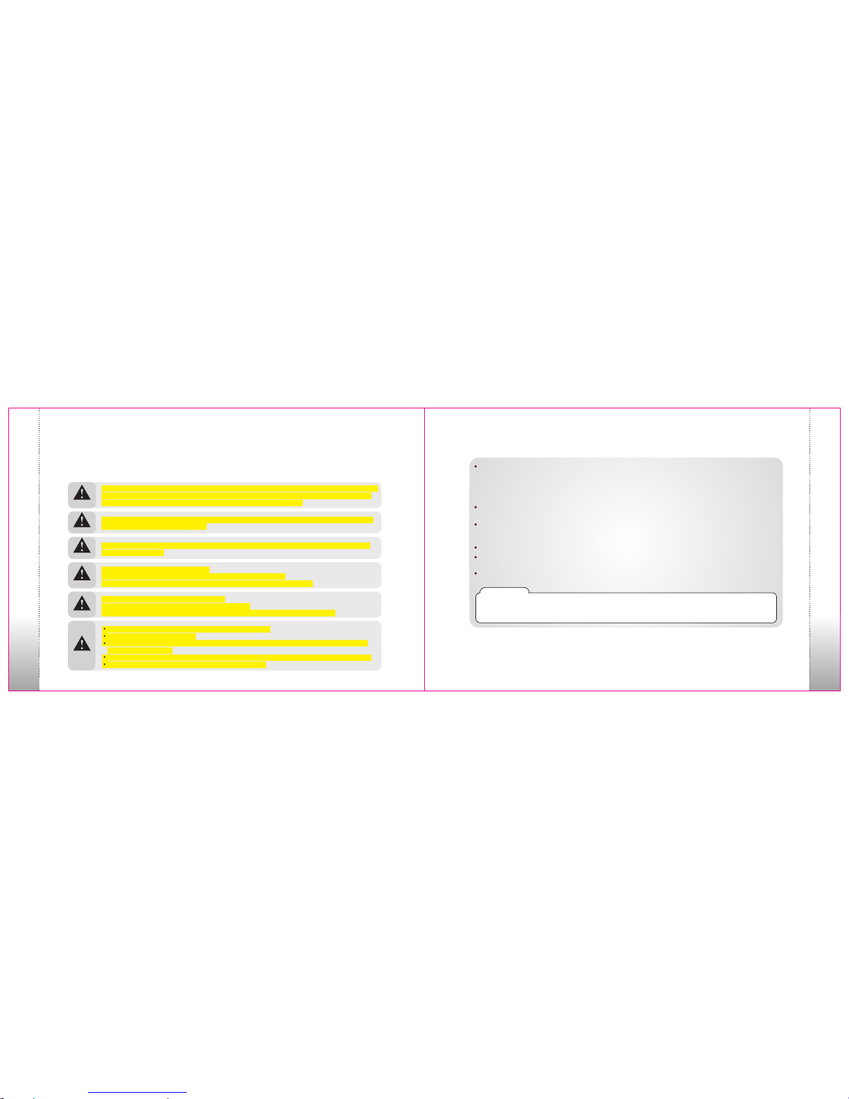
Safety Information
Please read the following safety guidelines. Nonobservance of these guidelines may cause danger or
violation of law.
Safety Information
Safety Information
03 04
Warning
Warning
Warning
Warning
Warning
Warning
The Federal Communications Commission (FCC), with its action in General Docket 93-62, November 7, 1997, has
adopted a safety standard for human exposure to Radio Frequency (RF) electromagnetic energy emitted by FCC
regulated equipment. Proper operation of this radio will result in user exposure far below the Occupational Safety and
Health Act (OSHA) and Federal Communications Commission limits.
FCC RF EXPOSURE COMPLIANCE REQUIREMENTS FOR OCCUPATIONAL USE ONLY
transmit for more than 50% of total radio use time (50% duty cycle). Transmitting more than 50% of the
time can cause FCC RF exposure compliance requirements to be exceeded.
This radio is NOT approved for use by the general population in an uncontrolled environment. This radio is restricted
to occupational use, work related operations only where radio operator must have the knowledge to control the user’s
exposure conditions for satisfying the higher exposure limit allowed for occupational use.
When transmitting, hold the radio in a vertical position with its microphone 1 inch (2.5cm) away from your mouth.
The radio is transmitting when the red LED on the front of the radio is illuminated. You can cause the radio to transmit
by pressing the PTT bar on the radio.
These are required operating configurations for meeting FCC RF exposure compliance. Failure to observe these
restrictions mean violation.
FCC Notice
This device complies with part 15 of the FCC rules. Operation is subject to the following two conditions: (1) This
device may not cause harmful interference, and (2) This device must accept any interference received, including
interference that may cause undesired operation.
DO NOT
Don’t transmit with antenna detached from the radio or don’t damage or change antenna type. Strong electronic
waves are emitted from the radio and damages or changes to the antenna may effect the performance of the
radio, and it may cause the radio to be defective and not covered under warranty.
Don’t use other manufacturers’ accessories. Unknown or unauthorized accessories may cause the radio to be
defective and not covered under warranty.
Don’t disassemble the radio. Disassembly of the radio may cause a serious defect or malfunction and not be
covered under warranty.
Don’t give an excessive shock to the radio.
Don’t place the radio where the direct sunlight or high temperature occurs.
Don’t make a damage to the battery pack by sharp substance or an excessive shock.
Turn off the radio before boarding on an airplane.
Don’t use the radio in the hospital without any pre-approval.
Don’t use the radio at the place of where computer of other electronic devices are being used.
Please keep the radio at least 1 inch away from the human body.
Don’t give any damage to antenna.
When using earphone, please reduce the volume to a low level. If not, unexpected high sound may have
harmful effect to your ear.
Don’t touch the conductive metal of the battery radio with wet hands. It may cause damage on your hands.
Please be careful when putting the battery in a pocket or a bag.
Page 6
05 06
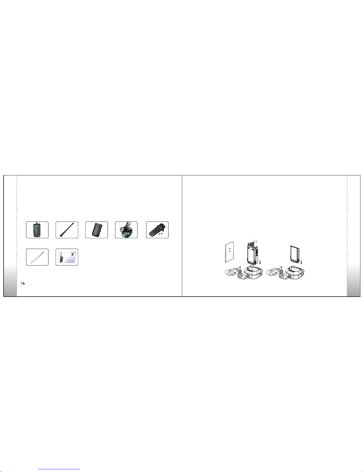
Items
Product Inspection
Thanks for choosing the TecNet TS-2000 Series radio. Before use, please check that the
following contents are included:
Radio
Qty: 1
TS-2116 or TS-2416 Antenna
Qty: 1
Li-Ion battery
Qty: 1
Charger
Qty: 1
Lanyard Strap
Qty: 1
Belt Clip with screws
Qty: 1
User Manual
Qty: 1
For any damage or lost contents, please contact your Authorized TecNet Dealer.
Note: For antenna identification, the frequency is marked on the color circle at the bottom of the antenna.
Please charge the battery as follows:
1.Turn off the radio for optimum charging.
2.Plug the AC connector of the adaptor into an AC (110V) outlet.
3.Insert the battery or radio equipped with battery into the charger.
• Red LED indicates battery is charging. Green LED indicates charging is complete.
• The battery is not charged at the factory.
Getting Started
Charging the Battery
Product Inspection
Getting Started
Page 7
0807
Attaching & Removing
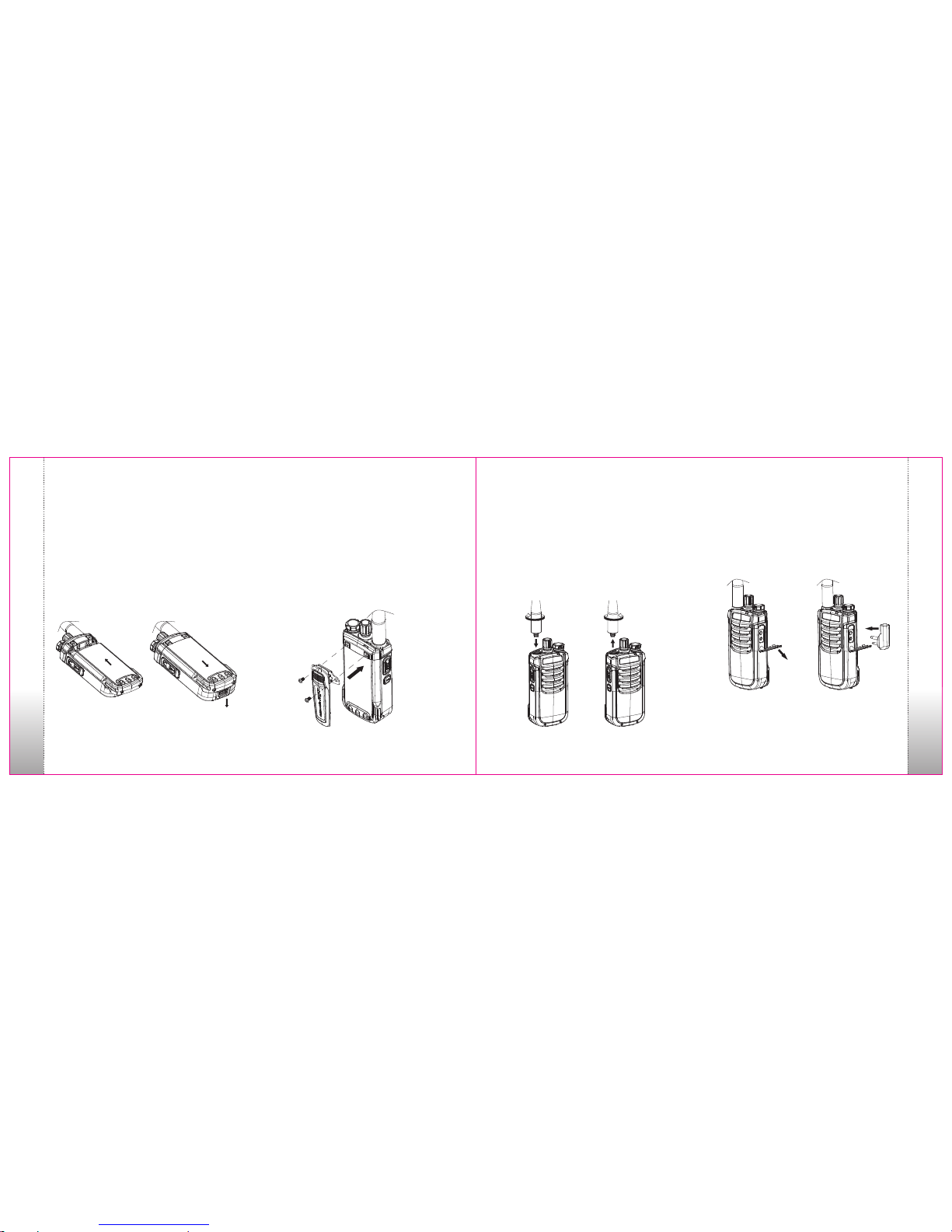
Attaching & Removing the Battery
1. For attaching, slide the battery up from the bottom
until it locks securely into place. (figure 1)
2. Before removing, make sure the radio is turned
off. For removal, push the battery lock and slide the
battery downwards. (figure 2)
Attaching & Removing the Belt Clip
To attach the belt clip, secure the belt clip with the 2
scr ews pro vided (Phi llip s head sc rewdr iver
required). To remove, reverse the screws and the
belt clip can be removed. (figure3). Note: the belt
clip does not need to be removed to remove the
battery.
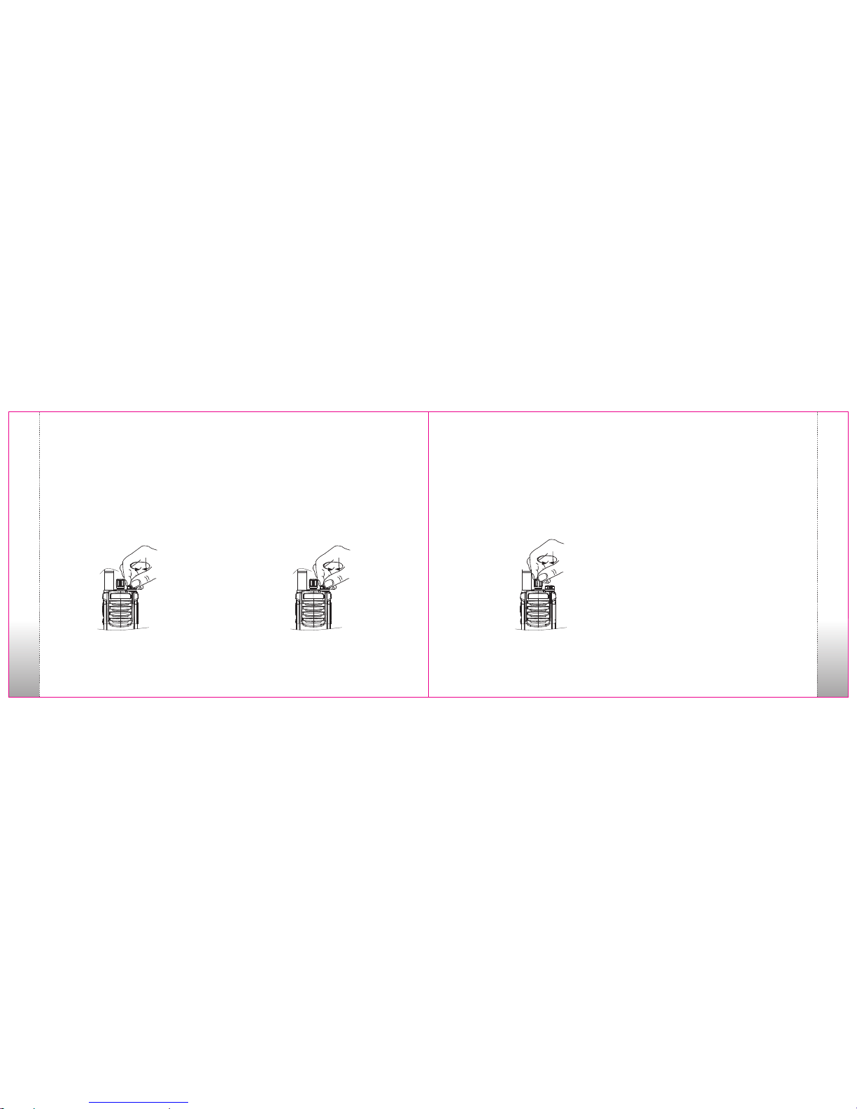
Attaching & Removing the Antenna
1. To attach, insert the antenna into the connector on
the top of the radio by holding the antenna at its
base and rotate the antenna clockwise to fasten it.
(figure 4) IMPORTANT: Do not over tighten
antenna as it will cause damage to the radio.
2. To remove, hold the antenna at its base and rotate
the antenna counter clockwise until you can remove
it. (figure 5)
Attaching External Audio Accessories
Pull down the cover of earphone/microphone jack
and insert the correct audio accessory into the jack.
Please make sure that the proper audio accessory is
being used and that it is properly seated in the jack.
(figure 6)
Attaching & Removing
Attaching & Removing
(figure 1)
(figure 2)
(figure 3)
(figure 4)
(figure 5)
(figure 6)
Page 8

09 10
1 2
3
4
6
7
8
9
10
12
5
11
Radio Overview
Antenna
1
Antenna with screwed connector is required for
proper transmit and receive of radio.
2
Channel Selector
Rotate clockwise or counter clockwise to select
operating channel.
3
Power Switch/Volume Control
Rotate the knob clockwise until a click sounds to
turn on the radio. Keep turning clockwise to increase
volume. Turn counter clockwise to decrease volume.
Keep rotating counter clockwise until a click
sounds to turn off radio.
4
LED Indicator
LED glows red during transmitting; glows green
during receiving; flashes red when battery power
is insufficient; flashes green during scanning.
5
Strap Hole
For use with lanyard strap.
6
Push-To-Talk (PTT)
Press PTT key to transmit; release it to receive.
7
Programmable Key
Default is battery check with short press and
monitor function with long press.
8
Audio Jack/Data Port
Connect the earphone/microphone or data cable.
9
Speaker
10
Microphone
11
Belt Clip
12
Li-Ion Battery
Radio Overview
Radio Overview
Page 9
Basic Operation
11 12
1. Turn On/Off
Turn on the radio by rotating Power Switch/Volume
Control knob clockwise until a click is sounded.
Turn off the radio by rotating Power Switch/Volume
Control knob counter clockwise until a click is
sounded.
2. Adjust Volume
Rotate Power Switch/Volume Control knob to adjust
volume when the radio is on.
Note: The volu me can also be adjus ted in accordance wi th
background n oise during monitori ng.
3. Channel Selection
Rotate the channel knob to select operating channel
from 1-16 or (15+Scan), according to the numbers
and symbols on the bottom of channel selector knob
or channel annunciation.
4. Make a Call
To make a call, press PTT key and speak into the
microphone with a normal voice. Keep the radio/
microphone area 2” (5 cm) away from your mouth.
5. Receive a Call
Calls can be received when PTT is released and the
radio is in standby mode.
Basic Operation
Basic Operation
Page 10

13
Programming Cable (optional)
14
Advanced Operation
Certain functions can be made possible through
progr amming so ftware as prog rammed by an
Authorized TecNet Dealer.
PC Programming
Turn off the radio and connect the programming
cable between the radio and PC. (See figure 7)
For the setting of parameters and writing to the
radio, please refer to the Help documents of the
software.
1.The receiving status of the selected channel can be
checked by a long press of the side button located
below the PTT (programmable key). This allows
the squelch to open on the radio so any received
audio can be heard. Default Mode: Press and hold
of the monitor button for up to 2 seconds to monitor
the channel for activity.
2.When this function is on, the volume can be adjusted
with the Volume Control.
Monitoring
1.The battery level/condition can be checked by a
short press of the side button located below the
PTT (programmable key). Default Mode: Press
momentary and release. The radio will announce
the power level as “high battery power”, “battery
middle power”, “low battery power” or “please
charge”.
2.This function is disabled/enabled through the
programming software (default is on).
Battery Power Check
1.With this function, users can receive calls in
CTCSS/DCS
correspondi ng channel s on ly w ith the same
CTCSS/DCS; without this function, users can receive
calling from all corresponding channels using the
same frequency.
2.This function is disabled/enabled through the
programming software.
1. When BCL is activated, it prohibits transmitting
on the channel if occupied by other users. This is
indicated by an audio alarm when pressing the
PTT.
2. When the channel becomes unoccupied, users can
resume talk.
3. This function is disabled/enabled through the
programming software (defalt is off).
Busy Channel Lockout (BCL)
1.This function is disabled/enabled through the
programming software (default is off).
2.If enabled, users can send DTMF code at start or
the end of transmission.
DTMF Encode
Advanced Operation
Advanced Operation
(figure 7)
Page 11

15 16
Voice Prompts
1.Channel voice: the radio would report the channel
information when you change the channel.
2.Low Power prompt: the radio would report low
battery information when the voltage reaches the
minimum operating voltage.
3.Scan Operation Prompt: the radio would report the
info rmatio n wh en t he c hannel s ets to the
designated scanning channel.
4.These prompts can be disabled/enabled through the
programming software.
Time Out Timer (TOT)
1. The TOT function prevents extended periods of
transmitting, which can cause possible damage to
the circuitry of the radio.
2. If transmitting occurs longer than the set time, the
radio will stop transmitting and an alarm will
sound. Cease pressing the PTT. Press PTT again to
resume transmitting.
3.Default is 180 seconds. The time duration can be
changed through the programming software.
1.VOX can be enabled to transmit without pressing
the PTT key when the voice signal is transmitted
through the microphone of the radio.
2.This function is disabled/enabled through the
programming software (default is off).
1.Through adjusting squelch level, the radio with a
lower squelch level allows weak signals to be
received.
2.Default level is 4. Levels can be changed through
the programming software, which ranges from 0-
9. When you choose 0, the squelch is open.
Higher numbers tighten the squelch reducing the
noise and interference.
Squelch Levels
VOX
Scan
1.This function is disabled/enabled through the
programming software (default is off).
2. When the scan function is enabled, channel 16
becomes the scan channel. The LED flashes green
and the radio will scan those channels assigned to
scan. If a signal is received, the radio will cease
Low Power Alert
1.When the battery power becomes low during
transmitting, receiving, or standby mode, the LED
will flash red and the radio will announce “battery
low”. You must charge the current battery or
replace with a fully charged battery.
Battery Saving
1.If there is no signal or operation after 5 seconds, the
battery saving function will occur automatically;
when signal is received or transmitted, the radio
will switch to normal power mode.
2.Multiple battery save functions can be done
through the programming software (default is on).
Advanced Operation
Advanced Operation
scanning and stop on that channel for the duration
of the call.
Page 12

1817
Optional Accessories
Optional Accessories are available according to your requirements, including:
Antennas
Clone Cable
Programming Cable
Wired Clone
Optional Accessories
Note:
If red and green lights on both master and slave radios
flash at the same time, it means cloning has failed.
Cloning can be done with the programming
software and cloning cable.
Connect the master radio to the slave radio with the
cloning cable, and then turn on the slave radio.
Press left lower key on master radio for about 3
seconds until LED glows red, release it, then LED
glows red and green at the same time, which
means the master radio is ready for cloning.
Short-press left lower key on master radio again,
the red light flashes, and green light on slave
radio flashes at the same time, after they stops
flashing, clone is finishing.
Change another slave radio, connect it to master
radio, and press left lower key on master radio
again for more same operation.
5.
4.
3.
2.
1.
Audio Accessories
Mas ter Rad io Sla ve Radi o
Gang Charger Carrying Cases
Page 13

19 20
Trouble Shooting
Problem
No Power
The battery power consumes
quickly after charge.
Can not communicate with other
members.
Voices of non-group members
are heard on the channel.
No sound or very low sound are
received by partner when
transmitting.
No reception on the channel.
Solution
The battery power may be insufficient. Please charge current battery
or change to a fully charged battery.
The battery life is finished; a new battery would be required.
Please check if your frequency and CTCSS/DCS are the same with
other members in your group.
Possibility of being too far away from other members. Please check
if you are within communication range.
Please change CTCSS/DCS, and change those of your members also.
Please check if the volume is turned to its highest level.
Be sure to speak directly into the microphone on the radio.
You may be too far away from other members and cannot receive.
Please check if you are within communication range and try again.
Care and Maintenance
These recommendations can help you use the radio
effectively and years of continued use.
Keep the radio dry. Rain, moisture or other liquid
may cause damage to the radio.
Do not throw, hit or vibrate the radio. This may cause
damage to the inner IC or other elements and void
the warranty.
Do not hold the radio by the antenna or external
audio accessories.
Please use the original or standard antenna. Unapproved
antenna or modifications of accessories may cause
damage to the radio.
Cover the earphone/microphone pad when not using
the radio for a long time.
Use a mild detergent (not corrosive chemicals) and
cloth to clean the casing.
All recommendations above also refer to the battery,
charger and accessories.
Note:
Trouble Shooting
Trouble Shooting
Page 14

21 22
TecNet warrants each new radio product manufactured
or supplied by it to be free from defects in material and
workmanship under normal use and service for the time
period stated, provided that the user has complied with the
requirements stated herein. The warranty period begins on
the date of purchase from an Authorized TecNet Dealer.
This warranty is not assignable or transferable. This
warranty is void if the product serial number is altered,
defaced or removed. TecNet is not responsible for any
equipment that is attached to or used in conjunction
with our products.
During the warranty period, if the product fails to function
under normal use, because of manufacturing defects or
workmanship, it should be returned to the Authorized
TecNet Dealer from which it was purchased. The
Authorized TecNet Dealer will repair the product or
return the product for repair to TecNet or its Authorized
Repair Depot. The user is responsible for the removal of
the product from a vehicle or any equipment attached to
it, or other site of its use; transportation of the product to
the Authorized TecNet Dealer; for the return of the
repaired or replacement product to the site of its use and
Warranty Statement
TecNet International, Inc. offers to the original end user:
One (1) Year Limited Warranty on TecNet Spartan Series
Radios (separate warranty period on accessories).
One (1) Year Limi ted Warranty on Accesso ries
(includes, but not limited to, batteries, antennas, belt
clips, chargers, audio accessories, nylon cases, leather
cases, etc.) and TBM Series Bluetooth kits.
for the reinstallation of the product.
TecNet shall have no obligation to make repairs or replacement
of product which results from normal wear and tear, or
is necessitated by catastrophe, fault, or negligence of the
user, improper or unauthorized alterations or repairs to the
product, incorrect wiring, use for which it was not designed
or by causes external to the product. TecNet’s sole obligation
shall be to replace or repair the product covered by the
warranty. Replacement is done at TecNet’s discretion and
may consist of a similar or higher featured product. Repair
may include the replacement of parts with functionally
equivalent new or reconditioned parts. All replaced parts
and accessories are warranted for the balance of the original
time period. All parts and accessories that are replaced
become the property of TecNet International Inc.
THE EXPRESS WARRANTIES CONTAINED HEREIN
ARE IN LIEU OF ALL OTHER WARRANTIES, EITHER
EXPR ESSED OR IMP LIED OR STATUTORY,
INC LUDI NG, W ITHO UT L IMITATIO N, AN Y
WARRANTY OF MERCHANTABILITY OR FITNESS
FOR A PARTICULAR PURPOSE.
FOR ANY PRODUCT THAT DOES NOT COMPLY
WITH THE WARRANTY SPECIFIED, THE SOLE
REMEDY WILL BE REPAIR OR REPLACEMENT. IN
NO EVENT WILL TECNET BE LIABLE FOR ANY
DA MA GE S, I NC LUD IN G A NY SP EC IA L,
INCIDENTAL, INDIRECT OR CONSEQUENTIAL
DAMAGES, OR THE LOSS OF PROFIT, REVENUE
OR DATA ARISING OUT OF THE USE OF OR THE
INABILITY TO USE THE PRODUCT.
Warranty Statement
Frequency Stability
Receiving Sensitivity
Audio Power
Weight
Dimension
±2.5PPM
0.2
700mW
170g
105×54×30mm
Channel Number
Normal Voltage
Working Temperature
16
DC 3.8V
-25℃~55℃
Output Power
2W/1W
Appendix I: Specification
Appendix
Appendix
Li-ion Battery
2000mAh
Antenna Impedance
TS-2116/TS-2416
Item
Frequency Range
136~174MHz/400~470MHz
Modulation Mode
Max. Frequency
Deviation
Audio Distortion
≤±5/2.5kHz
≤5%
Page 15
Appendix II: Technical Terms
23 24
Appendix
Appendix
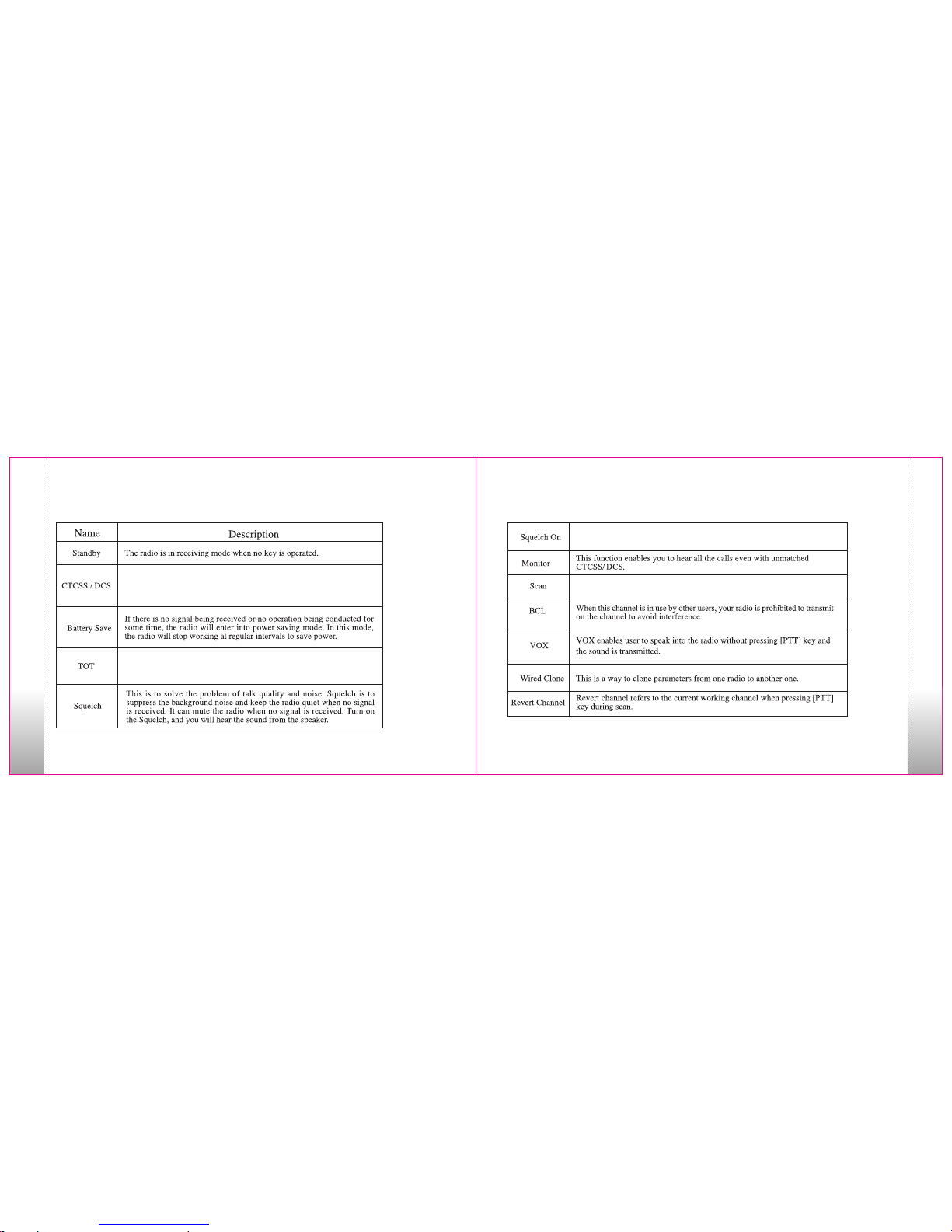
CTC SS/DC S is a tone a ttach ed to an au dio sig nal. If t he CTCS S
or DC S tone of t he tran smitt er matc hes tha t of the re ceive r, the
spe aker is u nmute d and the a udio wi ll be hea rd. If th ey do not
mat ch, no au dio wil l be hear d.
The Ti me Out Tim er (TOT ) is use d to prev ent ext ended p eriod s of
tra nsmit ting. I f an exte nded pe riod of t ransm ittin g occur s, this c an
cau se dama ge to the c ircui try of th e radio .
In th e on cond ition , the rad io is rec eivin g all aud io sign als.
All ows the r adio to r eceiv e calls o n multi ple cha nnels .
Page 16

25 26
Appendix
Appendix III: Frequency & Tone Chart TS-2116 (VHF)
1
2
3
4
5
6
7
8
9
10
11
12
13
14
15
16
151.6250
151.9550
152.8850
152.9150
151.7000
151.7600
152.9450
151.8350
151.8050
151.5125
151.6550
151.6850
151.7150
151.7450
151.7750
151.8650
151.6250
151.9550
152.8850
152.9150
151.7000
151.7600
152.9450
151.8350
151.8050
151.5125
151.6550
151.6850
151.7150
151.7450
151.7750
151.8650
67.0
67.0
67.0
67.0
67.0
67.0
67.0
67.0
67.0
67.0
67.0
67.0
67.0
67.0
67.0
67.0
N
N
N
N
N
N
N
N
N
N
N
N
N
N
N
N
TecNet TS Series
Model TS-2116 VHF Radio
Transmit (TX) Receive (RX)
CTCSS Tone
Bandwidth
Channel
Frequency Frequency
TX and RX
W/N
1
2
3
4
5
6
7
8
9
10
11
12
13
14
15
16
N
N
N
N
N
N
N
N
N
N
N
N
N
N
N
N
Appendix IV: Frequency & Tone Chart TS-2416 (UHF)
TecNet TS Series
Model TS-2416 UHF Radio
BandwidthTransmit (TX) Receive (RX)
CTCSS Tone
Channel
Frequency Frequency
TX and RX W/N
67.0
67.0
67.0
67.0
67.0
67.0
67.0
67.0
67.0
67.0
67.0
67.0
67.0
67.0
67.0
67.0
464.5000
464.5500
467.7625
467.8125
467.8500
467.8750
467.9000
467.9250
461.0375
461.0625
461.0875
461.1125
461.1375
461.1625
461.1875
461.2125
464.5000
464.5500
467.7625
467.8125
467.8500
467.8750
467.9000
467.9250
461.0375
461.0625
461.0875
461.1125
461.1375
461.1625
461.1875
461.2125
 Loading...