

Page 1
Thank you for your purchase and welcome to the TecNet family of
products. We proudly offer a 3 year warranty on the radio section
to insure that you are confident with your purchase for years to come.
As a product built to the Digital Mobile Radio (DMR) standards,
the TPD-1000 series of radios provide the latest in digital technology
with user- frie ndly ergonomics and t he h igh es t in production
standards to provide you stable and reliable communications.
Please read this manual and familiarize yourself with the radio
before use.
Welcome
11535 West 83rd Terrace, Lenexa, Kansas 66214
Phone: 913-859-9515 Fax: 913-8 59-9550
tecnet@tecnet usa.com
www.tecnetusa.com
User Manual
User Manual
Professional Digital and Analog Radio
Professional Digital and Analog Radio
Page 2
The Federal Communications Commission (FCC), with its action in General Docket 93-62, November 7, 1997, has
adopted a safety standard for human exposure to Radio Frequency (RF) electromagnetic energy emitted by FCC
regulated equipment. Proper operation of this radio will result in user exposure far below the Occupational Safety and
Health Act (OSHA) and Federal Communications Commission limits.
FCC RF EXPOSURE COMPLIANCE REQUIREMENTS FOR OCCUPATIONAL USE ONLY
transmit for more than 50% of total radio use time (50% duty cycle). Transmitting more than 50% of the
time can cause FCC RF exposure compliance requirements to be exceeded.
This radio is NOT approved for use by the general population in an uncontrolled environment. This radio is restricted
to occupational use, work related operations only where radio operator must have the knowledge to control the user’s
exposure conditions for satisfying the higher exposure limit allowed for occupational use.
When transmitting, hold the radio in a vertical position with its microphone 1 inch (2.5cm) away from your mouth.
The radio is transmitting when the red LED on the front of the radio is illuminated. You can cause the radio to transmit
by pressing the PTT bar on the radio.
These are required operating configurations for meeting FCC RF exposure compliance. Failure to observe these
restrictions mean violation.
FCC Notice
This device complies with part 15 of the FCC rules. Operation is subject to the following two conditions:
(1) This device may not cause harmful interference, and (2) This device must accept any interference
received, including interference that may cause undesired operation.
DO NOT
Safety Information
Please read the following safety guidelines. Nonobservance of these guidelines may cause
danger or violation of law.
Warning
Warning
Warning
Warning
Warning
Warning
Don’t transmit with antenna detached from the radio or don’t damage or change antenna type. Strong electronic
waves are emitted from the radio and damages or changes to the antenna may effect the performance of the
radio, and it may cause the radio to be defective and not covered under warranty.
Don’t use other manufacturers’ accessories. Unknown or unauthorized accessories may cause the radio to be
defective and not covered under warranty.
Don’t disassemble the radio. Disassembly of the radio may cause a serious defect or malfunction and not be
covered under warranty.
Don’t give an excessive shock to the radio.
Don’t place the radio where the direct sunlight or high temperature occurs.
Don’t make a damage to the battery pack by sharp substance or an excessive shock.
Turn off the radio before boarding on an airplane.
Don’t use the radio in the hospital without any pre-approval.
Don’t use the radio at the place of where computer of other electronic devices are being used.
Please keep the radio at least 1 inch away from the human body.
Don’t give any damage to antenna.
When using earphone, please reduce the volume to a low level. If not, unexpected high sound may have
harmful effect to your ear.
Don’t touch the conductive metal of the battery radio with wet hands. It may cause damage on your hands.
Please be careful when putting the battery in a pocket or a bag.
02
03
04
05
05
06
07
01
Attaching/Removing the Battery
Attaching/Removing the Antenna
Installing/Removing the Belt Clip
Installing Hand Strap
Attaching the Audio Accessory /Removing
Radio Overview
LED Indicator
11
Programmable Keys
12
Basic Operations
14
Calling on Digital Channel
15
15
15
Group Call
15
16
Zone
16
LED
16
Talk Around
17
Man Down (Optional)
17
Invalid Channel Indication
Squelch
17
Transmission Management
18
Optional Accessories
19
Troubleshooting Guide
20
Care and Maintenance
21
24
25
26
08
08
09
Contents
Safety Matters
Product Inspection
Getting Started
Battery Information
Attaching and Removing
27
Contents
Contents
Appendix 1
Appendix 2
Appendix 3
FCC Caution
All Call
Private Call
Page 3
01 02
03 04
Safety Matters
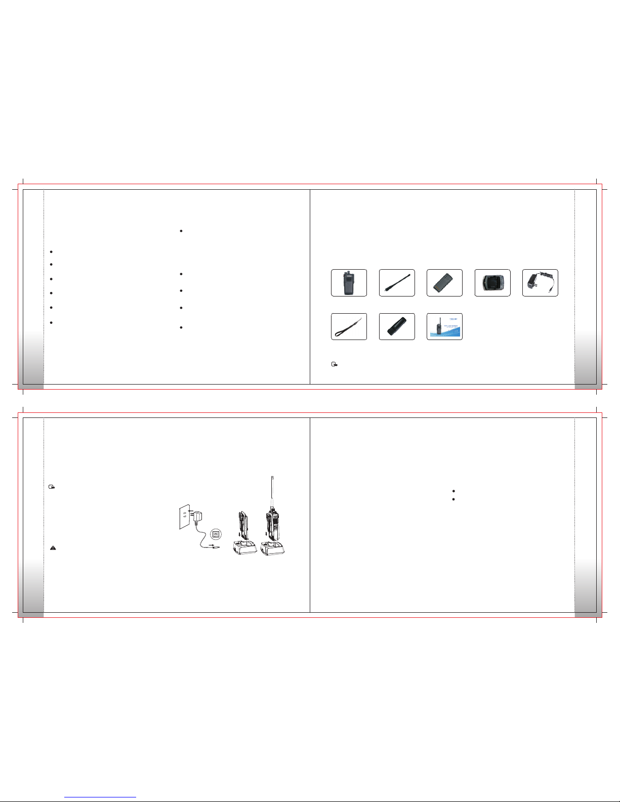
Product Inspection
Radio TPD-1000
Qty: 1
Battery
Qty: 1
Charger
Qty: 1
Adapter
Qty: 1
Lanyard Strap
Qty: 1
Belt Clip
Qty: 1
Antenna
Qty: 1
User Manual
Qty: 1
Items
Getting Started
Please opera te with TecNet approv ed battery onl y;
Using other batteries may cause personal damage and
void the warranty.
Getting Started
Battery Information
Note:
1. Do not short-circuit the battery terminals or dispose
the battery in fire. Never attempt to disassemble
the battery pack.
2. Charge the battery in 32 - 90 F (0-45℃) temperature.
Otherwise the battery may not obtain full charge.
3. Turn off the radio for optimum charging .
4. Do not charge if the battery or radio is wet. Both
battery and radio should be dry to avoid danger.
Charge Operation
Plug adapter into charger base, then wall adapter
Into outlet as follows:
Warning:
Treat any battery carefully when placing into pocket,
wallet, or any metal container. Conductive metals such
as jewel ry, key s, or decorating lace can cr eate a
short ci rc ui t when comi ng in con tact wi th battery
electrodes causing a large amount of heat.
3. Batteries will eventually need replacement, if low
battery is indicated quickly after if it has been fully
and correctly charged, this normally means the
battery needs to be replaced. Please contact yo ur
Authorized TecNet Dealer for information.
Antenna Information
Antenna length has a factor on distance of communication.
The communication range can be shortened based on
environmental or weather related issues such as rainy
days or dense forest.
1. Turn off the radio. Plug the DC connector of adapter
into the DC jack on the rear of the charger.
2. Plug the AC connector of adapter into an AC outlet.
3. After the charger is powered, the LED glows red for
1 seco nd and the n goes ou t. Thi s ind icat es t he
cha rger is read y for normal charging. I f th e L ED
flashes red continuously, the charger has encountered
an error and will need servicing.
4. Insert the battery or radio equipped with battery into
the c harge r. Make sure t he battery has a proper
connection with the charger electrodes.
5. LED glows red during normal charging; if LED flashes
red this indicates trickle charging because of very low
battery condition. After the battery reaches a certain
amount of capacity from trickle charge, the charger
automatically turns to normal charge mode.
6. The battery is fully charged when LED glows green.
Battery Charging Notes
1. The batter y is not charg ed at the fac tory. Plea se
charge the battery before initial use or after extended
period of storage.
2. For new batteries, repeat the charging process 2 to
3 times to obtain the best capacity.
Safety Matters
Please read the following safety guidelines.
Nonobservan ce of these rules may cause danger or
violation of law.
The use of this radio must compl y with regula tions
of local government.
Turn off the radio before you enter places of flammable
or explosive environments.
Do not replace or charg e battery pack in places of
flammable or explosive environments.
Turn off the radio before you approach blast area and /or
detonator area.
Do not use if the antenna is broken as it may c ause
minor burn to skin.
Only qualified technicians are allowed to maintain this
two-w ay rad io. Do not disa ssemb le the radio by
yourself as it will void the warranty.
To avoid prob lems caused by elec tromagneti c
inter ference or ele ctromagnet ic c ompat ibil ity,
pl ea se turn off the radio in places with “Wireless
Communication Transmit Equipment Prohibited”
posted, such as hospitals or other health care places.
When taking a plane, turn off the radio if required.
In a car with an air bag, do not place the radio within
area where air bag expands.
Do not expos e the radio to direc t sunlig ht or near
heating devices for a long period of time.
Keep the radio vertical and speak near the microphone
during transmi tting.
Make sure that the antenna is 1” (2.5 cm) away from
the body if you carry the radio on your body.
Thanks for choosing the TecNet TPD-1000 Series radio. Before use, please check that the
following contents are included.
If any item is missing or damaged, contact your Authorized TecNet Dealer.
Product Inspection
Note: For antenna identification, the frequency is marked on the color circle at the bottom of the antenna.
Getting Started
Page 4

(Figure 2)
(Figure 1) (Figure 3)
(Figure 4)
05 06
07 08
Attaching and Removing
Attaching and Removing
(Figure 6)
(Figure 5)
Installing Hand Strap
Thread the strap into the hole at the back of the radio
and fasten it.
Attaching the Audio Accessory
1. Remove the sc rew on th e acces sory ja ck cover,
open the accessory jack cover as figure show below.
2. Align the plug with the acc essory jack.
3. Tighten the scre w on the plug.
Removing the Accessory
To remove accessor ies, loosen the sc rew as figure
shown belo w.
(Figure 7) (Figure 8)
Attaching and Removing
Attaching and Removing
Slide the battery dow n and away from the radio.
See Figure 4.
To remove the battery, first make sure the rad io is
turned off, then push the battery latch in the opposite
direction of the word “LOCK” to unlock it, and push
the bat tery latch downwards. See Figure 3.
Removin g the Battery
Match the two grooves of battery with corresponding
guide s on the back of the ra dio. Make sure that full
contact is made between the battery and radio chassis.
Attachi ng the Battery
Push t he battery u p along the guide until the battery
latch locks. See Figure 1.
Attaching and Removing
Push the b attery la tch towards th e word “Loc k” to
lock it. S ee Figure 2.
Attachi ng the Antenna
Insert the antenn a into the conn ecto r on th e to p of
radio by holding the antenna at its base.
Rotate the antenna clockwise to fasten it. See Figure 5.
IMPORTANT: Do not over tighten antenna as it
will cause damage to the radio .
Remo ving the Antenna
Rotat e the ant enna coun ter clockwi se until you c an
remov e it. See Fi gure 6.
Attaching Belt Clip
Removing Belt Clip
Match the grooves of belt clip with those on the rear of
radio and press the belt clip downwards until it is locked.
See Figure 7.
Lift the metal spring piece in the belt clip from topside
and pull the belt clip upward from the battery pack.
See Figure 8.
Note: For ease of installation and removal of belt clip,
remove the battery from the radio.
Page 5

09 10
11 12
Radio Overview
Radio Overview
Radio Overview
1. Push-To-Talk (PTT Key)
2. Side Key 1 (SK1)
3. Side Key 2 (SK2)
4. Side Key 3 (SK3)
5. Speaker
6. Microphone
7. Unit Case
8. Radio On-Off/Volume Control Knob
9. LED Indicator
10. Channel Selector Knob
11. Top Key (TK)
12. Antenna
13. Nameplate
14. Accessory Jack
16.
17. Strap Hole
18. Belt Clip
19. Battery
20. Charging Contacts
15.
Battery Latch
Accessory Screw
glo ws red.
glo ws gree n.
No.
Shortcut Keys
Description
1
2
3
4
5
6
7
8
9
10
11
12
13
None
Zone Down
Zone Up
Scan
Nuisance Temporary Delete
Emergency On
Emergency Off
Adjust Power Level
Adjust Squelch Level
One Touch Call 1
One Touch Call 2
One Touch Call 3
One Touch Call 4
No feature will be assigned.
To select a desired zone quickly
To select a desired zone quickly
To receive signals on other channels
To temporarily ignore unwanted channel activity
To summon help in emergent situations
Emergency function is off
To adjust power level
To adjust the squelch threshold required for the speaker to unmute
To transmit a call quickly
To transmit a call quickly
To transmit a call quickly
To transmit a call quickly
LED lndicator
LED lndicator
The top LED indicator will help you easily identify current radio status.
For enhanced convenience, you may request your dealer to program the keys SK1, SK2, SK3, and TK as
shortcuts to the functions listed below:
Programmable Keys
flashes green.
fla shes or ange.
Page 6

13 14
15 16
No.
Shortcut Keys
Description
14
15
16
17
18
One T ouch Cal l 5
Squelch Off Momentary
Squelch Off
Monitor
Talk A round
To transmit a call quickly
To momentary open the speaker
To always open the speaker
To adjust the condition for incoming signal match
To directly communicate with other radios
Scramble: To encrypt your voice so as to guarantee privacy of your communication
Encrypt: To encrypt your voice and message so as to guarantee privacy of your communication
To enable or disable the VOX function
Scra mble/ Encry pt
VOX
Programmable Keys
Basic Operations
Note: (1) Long and short press of a key can be assigned with different functions by your dealer.
(2) The TK is programmed as the Emergency Key by default, and is programmable by your dealer.
Basic Operations
Basic Operations
Turning the Radio On/Off
Rotate the Radio On-O ff/Volume Contr ol knob clockw ise/
counter-cloc kwise until a click i s hea rd to turn the r adio
on/off.
After turning the radio on, rotate the Radio On- Off/Volume
Control knob clo ckwise to increase the volum e, or counterclockwise to decrease the volume.
Digital/Analog switch
Adjusting the Volume
Basic Operations
20
19
Scan On/Off
The func tion “Scan” all ows you to listen to co mmunicati on
activ ities on other cha nnels so that you c an ke ep a c lose
track of your team members. This function is enabled or
disa bled by pr essing t he short cut key fo r scan. Co ntact
your Au thoriz ed TecNet Dea ler for mo re infor mation .
Zone
This radio supports up to 64 zones. You can set it by CPS.
LED
VOX
If enabled, the VOX functi on allows users to transmit
every time the user speaks into the radio directly without
pressing the PTT key.
All LEDs: to enable /disable all LED indications.
TX LED: to set whe ther the Tx LED indica tes during
RX LED: to set whether the Rx LED indic ates during
reception.
Scan LED: to set whether the Scan LED in dicat es in
Scan mode.
transmission.
Low Battery LED: to set whether the Low Battery LED
indicates when the battery is low.
Carrier LED: to set whether Carrier LED indicates when
receiving carrier.
Note: Please contact your Authorized TecNet Dealer
for setting.
call to the contact (a Private Call number) preset for the current
channel.
Note: Your dealer may preset a contact for each digital channel.
The preset contact could be a Private Call number, a Group Call
number or an All Call number.
Receiving and Responding to a Private Call
Responding to a Private Call, after a Private Call is received,
you may press the PTT key within the preset time period to call
back.
In standby mode, pressing PTT key will transmit an individual
Private Call
Each channel can be programmed as either analog channel
or digital channel, if the current zone includ es both analog
and digital channels, you may switch b etwee n digit al and
analog through the channel sele ct knob.
Selection a Channel
Rotate the Cha nnel Selector knob to sele ct a
CH01-CH 16 according to the number sh own at the botto m
of the channel sel ector.
channel fro m
Selecting a Zone
A zone is a group of channels exhibiting the same pr operty, and
is programmed by your dealer. The radio supports up to 64 zones,
each with a maximum of 16 channels. You m ay select a zone
through the funct ion key s - You may quickl y toggle to your
desired zone by p ressi ng the programmed Zone Up or Zone
Down key.
In standby mode, pressing PTT key will transmit a group call
to the contact (a Group Call number) pr eset for th e cur ren t
channel.
Note: Your dealer may preset a contact for each digital channel.
The preset contact could be a Private Call number, a Group Call
number or an All Call number.
Receiving and Responding to a CallGroup
Responding to a Call, aft er a Call is received,
you may press the PTT key within the preset time period to call
back.
Group Group
Transmitting an All Call
Methods are the same as those in Transmitting a Group Call.
All Call
Making a Call on Analog Channels
To make a call , hold d own [P TT] ke y and speak into t he
micropho ne with normal voice. Please keep the microphone
2.5-5cm awa y from your mout h.
Note:
1. Hold down [P TT] key and the radio begins to transmit
when LED glows red.
2. When the bat tery power is lower than normal battery power,
the transmission is prohibited.
Talk Around (TA)
You can continue to communicate in DM mode by pressing
the programmed Talk Around key. Contact your Authorized
TecNet D ealer fo r more in formati on.
TA Operation
Press the programmed Talk Around key to switch between DM
mode and RM mode.
Monitor (Analog Only)
The monitor function bypasses the programmed signaling
on a channel.
Monitor Operation
Press the programme d Monitor key to enable the
feat ure . To dis abl e the fe ature, pre ss thi s key
again.
Press the programmed Squel ch Off Mom entary ke y
to en abl e t he f eat ure . T hen th e ra di o s oun ds
background noise. To disable the feature, release this key.
Squelch Off Operation
Press the p rogra mmed Squelch Off key to enable
the fea ture. Then the r adio soun ds backgro und
noise. To disable th e featur e, press this key again .
Vibration (Optional)
If vibrate is included, this option allows the user to enable/
dis able th e feature. Contact your Authorized
TecNet Dealer for more information.
Group Call
Page 7

Transmission Management
19 20
1817
occupying a channel for an extended period.
If the preset time expires, the radio will automatically
terminate transmission and maintain the alert.
To stop the alert, please release the PTT key. You
must wait for a certain time period before you can
press and hold down the PTT key to transmit again.
If the pre-alert function is set, the radio will alert the
TOT expiration in advance. Contact your Authorized
TecNet Dealer for more information.
The purpose of TOT is t o prevent any u ser f rom
Note: This feature is null in Emergency mode.
Time-Out Tim er (TOT)
Busy Channel Lockout
can prevent your radio f rom interfering with other
radios transmitting on the same channel. If you hold
down the PTT ke y whi le the c hannel is in us e,
your radio will sound an alert , adv ising you that
transmission is prohibited. To stop alert, release the
PTT key.
If enabled via the programming software, this feature
Transmission Management
This option defines the response from the transmitter upon PTT press on the current channel, in order to
prevent the user transmitting on channels that are already in use. It can be programmed via the CPS.
In Analog mode, the options as below:
Always Allow: The user can transmit all the time.
Channel Free: The radio allows transmission only when the current channel is free.
CTCSS/DCS Correct: The radio allows transmission upon CTCSS/DCS match.
CTCSS/DCS Incorrect: The radio allows transmission upon CTCSS/DCS not matched.
In Digital mode, the options as below:
Always Allow: The user can transmit all the time.
Channel Free: The radio can transmit only if the channel is free.
Color Code Free: The radio can transmit only when the channel is free or the color code is not matched.
Optioanl Accessories
Issue
Analysis
Solution
The equipment can
not be powered on.
During receiving
signals, the voice
is weak,
discontinuous or
totally inactive.
You can not
communicate with
other members.
Irrelevant
communications or
noises are heard
on the channel.
The battery may run out.
The battery may be improperly installed.
The battery may suffer from poor contact
caused by tarnished or damaged battery
contacts.
The battery strength may be too low.
The volume may be set to a low level.
The antenna may be loose or
improperly installed.
The speaker may be blocked or damaged.
The frequency or signaling may be
inconsistent with that of other members.
The channel type (digital/analog) may be
set inconsistently.
You may be too far away from the group
members.
You may be interrupted by radios using the
same frequency.
The radio may not be set with any signaling.
Remove the battery and attach it again.
Recharge or replace the battery.
Clean the battery contacts. If the problem cannot
be solved, contact your dealer or authorized service
center for inspection and repair.
Recharge or replace the battery.
Increase the volume.
Power off the radio, and re-install the antenna.
Clean surface of the speaker. If the problem can not
be solved, contact your dealer or authorized service
center for inspection and repair.
Set your TX/RX frequency and signaling to the same
as that of other members.
Make sure all members are on the same digital/
analog channel.
Move closer towards other members.
Change the frequency, or adjust the squelch level.
Set signaling for all member radios to avoid
interference at the same frequency.
Troubleshooting Guide
Troubleshooting Guide
Optional Accessories
Optional accessories and replacement parts are available through your Authorized TecNet Dealer.
Those items include:
VHF antennas
UHF antennas (with optional GPS)
Batteries
Belt Clips
Audio Accessories
Speaker Microphones
Ear hook Speaker with in-line PTT
Discreet ear speaker with in-line PTT
Single unit chargers
Vehicular chargers
Six unit gang chargers
Carrying cases
Programming Cable
Programming Software
Invalid Channel Indication
If current operating channel is an invalid channel, the
radio will send a continuous alert tone, which means
the current channel is unable to transmit or receive.
Squelch
Setting the squelch level decides how strong the signal
is needed to un-mute the receiver. Se tting range is
0~9, selecting “0 ” causes th e squel ch to open easily.
The higher the squelch level, the harder to open the squelch.
Your dealer preset a squelch level for analog channel.
Man Down (Optional)
With this feat ure (only in digital mode), your radio will
alarm autom atical ly when it is tilts to a certain gradient
for a certain time period. Please contact your
Authorize d TecNet Dealer for more information.
Basic Operations
Contact your Authorized TecNet Dealer for more information.
Page 8

21 22
23 24
Warranty Statement
Warranty Statement
TecNet International, Inc. offers to the original end user:
Three (3) Year Limited Warranty on TecNet TPD-1000 Series radios (separate warranty period on accessories).
One (1) Year Limited Warranty on Accessories (includes, but no t limited to, batter ies, anten nas, belt clips,
chargers, audio accessories, nylon cases, leather cases, etc.) .
TecNet warrants each new radio product manufactured or supplied by it to be f ree from d efects in material
and workmanship under normal use and service for the time period stated, provided that the user has complied
with the requirements stated herein. The warranty period begins on the date of p urcha se fr om an Autho rized
TecNet Dealer. This warranty is not assignable or transferable. This warran ty i s voi d if t he p roduc t seri al
number is altered, defaced or removed. TecNet is not responsible for any equip ment that i s attac hed to or
During the warranty period, if the product fails to function under normal use, because of manufa cturing defects or
workmanship, it should be returned to the Authorized TecNet Dealer from which it was purchased. The Authorized
TecNet Dealer will repair the product or return the product for repair to TecNet or its Authorized Repair Depot.
The user is responsible for the removal of the product from a vehicle or any equipment attached to it, or other site
of its use; transportation of the product to the Authorized TecNet Dealer; for the return of the repaired or replacement
product to the site of its use and for the reinstallation of the product.
TecNet shall have no obligation to make repairs or replacement of product which results from normal wear and
tear, or is necessitated by catastrophe, fault, or negligence of the user, improper or unauthorized alterations
or repairs to the product, incorrect wiring, use f or whic h it was n ot designe d or by cause s ext ernal to t he
product. TecNet’s sole obligation shall be to replace or repair the product covered by the warranty.
Replacement is done at TecNet’s discretion and may consist o f a similar or higher fea tured product. Repai r
may include the replacement of parts with functionally equiv alent new or reconditio ned parts. All r eplaced
parts and accessories are warranted for the balance of the original time period. All parts and accessories that
are replaced become the property of TecNet international. Inc.
THE EXPRESS WARRANTIES CONTAINED HEREIN ARE IN LIEU OF ALL OTHER WARRANTIES, EITHER
EXPRESSED OR IMPLIED OR STATUTORY, INCLUDING, WITHOUT LIMITATION, ANY WAR RANTY O F
MERCHANTABILITY OR FITNESS FOR A PARTICULAR PURPOSE.
FOR ANY PRODUCT THAT DOES NOT COMPLY WITH THE WARRANTY SPECIFIED, THE SOLE REMEDY
WILL BE REPAIR OR REPL ACEME NT. IN NO EVEN T WILL TECNET BE LI ABLE FOR ANY DAMAG ES,
INCLUDING ANY SPECIAL, INCIDENTAL, INDIRECT OR CONSEQUENTIAL DAMAGES, OR THE LOSS
OF PROFIT, REVENUE OR DATA ARISING OUT OF THE USE OF OR THE INABILITY TO USE THE PRODUCT.
Care and Maintenance
Use lint-free cloth to clean the LCD display.
Note:
All r ecommendations above a lso refer to your
charger and accessories.
Do not th row, hit or vibr ate the radi o. This may
cause dam age to the inner IC or other elemen ts
and v oid the w arran ty.
battery,
Use m ild det ergen t or warm w ater (n ot
cor rosiv e chemi cals) t o clean t he casi ng.
To incr ease th e life of y our rad io, ple ase tak e
not e of the fo llowi ng:
Do no t hold or c arry th e radio b y the ant enna
or ex terna l audio a ccess ories .
Use o nly ori ginal Tec Net par ts or accessories.
Use o f non-appro ved parts or accessori es may
cause damage to the radio and void the warranty.
Cover the aud io accessor y jack when not usin g
audio acc essorie s.
Care and Maintenance
Warranty Statement
TPD-1116/1416
2000mAh
16
FM/4FSK
7.4V
320g
1.5W
UHF:4W/1W
3%
Appendix 1: Specification
Item
Audio Distortion
Sensitivity
Max Audio Output
Power
Battery
RF Output Power
VHF:5W/1W
0.22μv
VHF: 1 36~17 4MHz
UHF: 4 00~47 0MHz
450~ 520MH z
-30 60
130 X55X3 4mm
Item
Frequency
Range
Channel Capacity
Modulation Type
Frequency Stability
Operating
Temperature
Antenna Impedance
Operating Voltage
Weight (with antenna
& battery)
1.0ppm
Appendix
TPD-1116/1416
Page 9

1
2
3
4
5
6
7
8
9
10
11
12
13
14
15
16
Appendix 2 : Frequency Chart (Used to record the frequency.)
Model:
S e r i a l number:
Tx Frequency
Channel
Tx Contact
Rx Frequency
Rx Group List Color Code
25 26
Appendix
D i g i t al Zone:
1
2
3
4
5
6
7
8
9
10
11
12
13
14
15
16
Model:
S e r i a l number:
Tx FrequencyChannel Tx CTCSS/CDCSS Rx Frequency Rx CTCSS/CDCSS
Optional Signaling
A n a l og Zone:
Appendix
FCC Caution
Appendix 3 : Frequency Chart (Used to record the frequency.)
27
Any Changes or modifications not expressly approved by the party responsible for compliance could void the user's
authority to operate the equipment. This device complies with part 15 of the FCC Rules. Operation is subject to the
following two conditions: (1) This device may not cause harmful interference, and (2) this device must accept any
interference received, including interference that may cause undesired operation. This equipment complies with FCC
radiation exposure limits set forth for an uncontrolled environment . This equipment should be installed and operated
with minimum distance 20cm between the radio and your body. This transmitter must not be co-located or operating
in conjunction with any other antenna or transmitter.
Your TecNet Internation al, Inc. 2-way radio is designed and tes ted to comply with a number of na tional an d
international standards and guidelines (listed below) for human exposure to radio frequen cy electromagnetic.
This radio complies with the IEEE and ICNIRP exposure limits for occupational/controlled RF exposure environment
at operating duty factors of up to 50% transmitting and is authorized by the FCC for occupational use only. In terms of
measurable RF energy only while it is transmitting (during talking), not when it is receiving (listening) or in standby mode.
Note: The approved batteries supplied with this radio are rated for a 5-5-90 duty factor (5% talk -5% listen -90% standby)
even though this radio complies with the FCC occupational RF exposure limits and may operate at duty factors of
up to 50% talk.
Your TecNet International, Inc. 2-way radio complies with the following RF energy exposure standards and guidelines:
United States Federal Communications Commission, Code of Federal Regulations; 47CFR §§1.1.307,1.1310,
FCC Caution:
2.1091 and 2.1093
American National Standards Institute(ANSI)/ Institute of Electrical and Electronic Engineers (IEEE) C95.1-1992
Institute of Electrical and Electronic Engineers (IEEE) C95.1-1999 Edition
 Loading...