

TecNec PNCH-1 Operation Instructions Manual
SPECS
SPECS
Operation Instructions
PNCH-1
One-2-Punch Specialized Router For
Non-Linear Editing Applications
SPEC
TEC
NEC
ALWAYS
SM

One-2-Punch Specialized Router For
Non-Linear Editing Applications
PNCH-1
4 High Street • Saugerties, NY 12477
A Division of Tower Products, Inc.
Source & Record Connections: RS422: 9pin D-sub Female
Configurations: Video: R-Y,B-Y,Y or YUV
YC and 1 Composite Video
3 Composite Video
Rear panel has 3 BNC lines which can be configured for any of the above
configurations
Configurations: Audio: Dual Channel: Balanced Neutrik XLR Connectors.
Front Panel Controls: Source/Record: RS422 Control, Video (Beta/YC/Composite), Audio
SOLO - AUTO: Control, Video, Audio
Status Indicators: LEDs: Source - Record Select
Power: For LEDs & Switch Control Only: 12VDC 500Ma Power Pack
Dimensions: 3.50" H X 7"D X 19"W EIA rackmount
Weight: 8 lb. without shipping carton
SPECIFICATIONS
• •
1
CONTROL VIDEO AUDIO
SOLO AUTO SOLO AUTO SOLO AUTO SOLO AUTO SOLO AUTO SOLO
REC-1
REC-2
12VDC
OUT
Made In USA By TecNec Div. Tower Products, Inc. ©1998, Patent Pending
INPUT SOURCE RECORD OUTPUT
21 21 2
R-Y B-Y Y R-Y B-Y Y
Specialized Router For Editing Systems
CH-1 CH-2
NEUTRIK NEUTRIK
REC-1
REC-2
CH-1 CH-2
CONTROL
AUTO
CH-1 CH-1 CH-1 CH-2
•
Push
NEUTRIK
EDITOR
OUT
NEUTRIKNEUTRIK
NEUTRIK
CH-2 CH-2 CH-1 CH-2
NEUTRIK
EDITOR
IN
Push
NEUTRIK
•
121212
AUTO
CONTROL VIDEO AUDIO
AUTO
One-2-Punch
Push
NEUTRIK
Push
NEUTRIK
SOURCE-1
SOURCE-2
Push
NEUTRIK
Push
NEUTRIK
™
SOURCE-1
SOURCE-2
IN
One-2-Punch Specialized Router For
Non-Linear Editing Applications
PNCH-1
4 High Street • Saugerties, NY 12477
A Division of Tower Products, Inc.
You have just purchased the most innovative, flexible and powerful system interface available today.
The One-2-Punch is the ultimate product for solving all your non-linear edit system signal and device
routing needs. Designed and developed by both engineers and top video production editors, the One-
2-Punch was designed for user friendly setup & operation. If you have any questions or need additional assistance, please call our factory at 914-247-0680, Monday-Friday from 10AM to 4PM EST.
We will be happy to help you with any application questions or problems you may have.
The One-2-Punch was developed as an interface device for the new NON-LINEAR EDIT SYSTEMS. Most of the popular
Non-linear edit systems today, such as the AVID and the MEDIA 100, are designed with a single Audio/Video input-output
port and a single RS422 machine control por t. In the real world of production, it becomes necessary to use more than
one source or record VTR or signal device. This allows the editor to take advantage of footage mediums such as SVHS,
Hi-8 and other formats such as computer generated graphics. Without an interface such as the One-2-Punch, the user
would be constantly unplugging and reconnecting cables. This takes time, and is also messy and inefficient. The One-2-
Punch solves the complete interface issue in a 2 rackmount cabinet.
The One-2-Punch is, in all respects, a passive audio-video-RS422 2X2 router. The unit can accept 2 different and separate source devices (such as VTRs) and digitize from either source into the Non-Linear editor. After the effects and creative work is completed, the unit can send the clip to either of 2 different or separate recording devices(such as VTRs). All
audio signals(dual channel balanced) and video signals(R-Y, B-Y or SVHS or RGB) are connected into the rear panel of
the One-2-Punch. All 4 RS422 lines are also connected to the rear panel.
The audio-video I/O ports of the Non-Linear unit are also connected to the One-2-Punch. The single RS422 control cable
from the Non-Linear unit is then connected to the SOURCE RS422 9-Pin port marked “IN”.
Now all control and selection is controlled from the front panel. You are set to wor k with no fuss and cable mess. Status
LEDs on the front panel indicate all the settings in all modes of operation.
The One-2-Punch is split into 2 sections: SOURCE and RECORD. These designations are so named to keep you oriented to a system flow. The One-2-Punch accomplishes all switching of data and signals by PASSIVE means. This concept
allows the selection and switching to be performed absolutely transparent with no processing at all: What you feed is what
is returned. Another advantage of passive switching is its bi-directional path. Despite the fact that diagrams have arrows
show signal direction, the One-2-Punch por ts can be used in either SELECT or ASSIGNMENT configurations. This
makes the One-2-Punch extremely flexible and can therefore be used in many system setups to solve interface problems.
Use the diagrams provided to get an idea of the setup you may require. If you should require additional configuration information or help: CALL US. Our tech suppor t representatives are ready and able to assist you. Diagrams are also available on our WEBSITE and will be continually updated as more ideas are submitted by our customers.
BASIC SETUP
ONE-2-PUNCH NOTES
One-2-Punch Specialized Router For
Non-Linear Editing Applications
PNCH-1
4 High Street • Saugerties, NY 12477
A Division of Tower Products, Inc.
1.
As stated, the front panel is divided into 2 identical sections designated as SOURCE and RECORD. Each section has 3
toggle switches located between 2 LEDs: one green and the other red. Located below each of these switches is another
toggle switch designated SOLO and AUTO.
1.1 1-2 SELECTOR SWITCHES
These toggle switches are only enabled when the SOLO-AUTO switch below it is in the SOLO POSITION. In this
mode the 1-2 toggle switches will select either device 1 or 2 as required. AUDIO , VIDEO , and/or RS422 can be selected for either device. This feature is useful when the need exists for previewing a clip from VTR#1 while compiling
footage from VTR#2. All three switches work independently once the SOLO feature has been enabled by the SOLO-
AUTO switch.
1.2 AUTO SWITCH
At the very center of the panel are two large square push-button switches designated:AUTO. The graphics indicate
that the left switch controls the SOURCE side and the right switch controls the RECORD side. These are PUSHLATCHING switches. Just push in to activate and push again to release. The switches are equipped with a BICOLOR illumination device which changes color to immediately indicate its position. When pushed-in (AUTO
SELECT: 2), the color is GREEN. When released (AUTO SELECT: 1), the color is RED.
1.3 SOLO-AUTO SWITCHES
In the SOLO mode, this switch allows the selection of information based on the operation described above. In the
AUTO mode, control is designated by the large AUTO push-button switches. If all three SOLO-AUTO switches are in
the AUTO position, then just pressing and releasing the AUTO switch will select either machine 1 or 2 accordingly.
You may place any of the 3 SOLO-AUTO switches in the AUTO mode as required. In this configuration, the AUTO
switch overrides the position of each 1-2 selector switch and routs either machine based on the “pushed-in” or
“release” position described in paragraph 1.1.
1.4 CONTROL TOGGLE SWITCH
Located directly above and between the two AUTO switches is the RS422 control selector switch. Since Non-Linear
Edit Systems usually only have one RS422 port, it is necessary to let the edit computer know where to look for its
controlled device. During the digitizing phase (SOURCE SELECT), the control toggle must be in the SOURCE direction. Now it will route either VTR selected to the editor RS422 port. When you are ready to output the signal to one
of the record VTRs, the switch must be in the RECORD position. This then allows the editor to control either of the
selected VTRs. This system is the answer to the multiple VTR but single RS422 port problem. In this setup, the
RS422 connection from the One-2-Punch and the Non-Linear Edit System is made via the SOURCE IN 9-Pin connector located at the bottom of the cabinet. There is no need to connect the RECORD 9-Pin bottom port, unless a
dual Non-Linear configuration is used as in DIAGRAM 1-A (NEXT PAGE).
FRONT PANEL SELECTORS
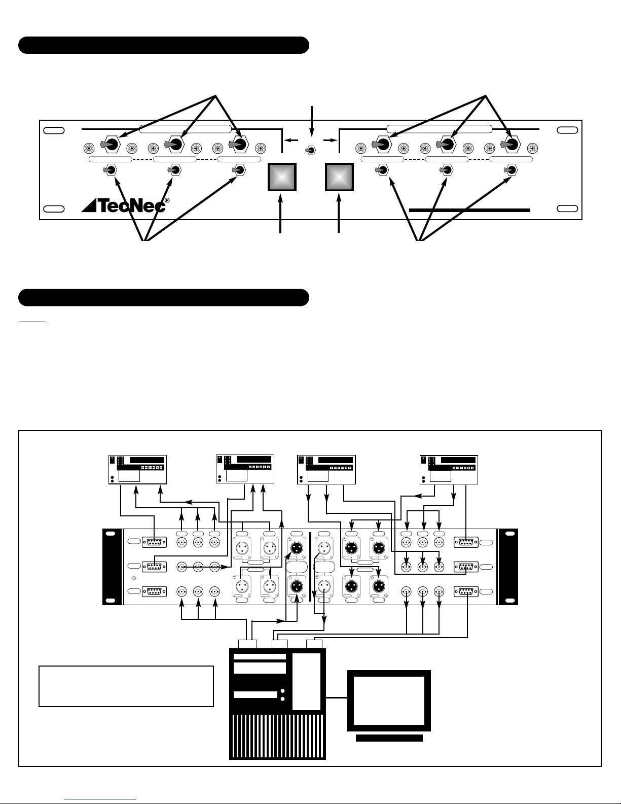
SOLO-AUTO
SWITCHES
SOLO-AUTO
SWITCHES
SOURCE 1-2
SWITCHES
AUTO
RECORD
SWITCH
AUTO
SOURCE
SWITCH
RS422
CONTROL
SWITCH
RECORD 1-2
SWITCHES
RS422
VIDEO
VTR 1 - Sony
Beta Player
VTR 2 - Sony
Beta Player
RS422
VTR 2 - Sony Beta
Recorder
VTR 1 - Sony Beta
Recorder
RS422
VIDEO
VIDEO
AUDIO
VIDEO
RS422
AUDIO
AUDIO
AUDIO
VIDEO
RS422
VIDEO
IN I/O
OUT
TYPICAL APPLICATION DIAGRAMS
FRONT SWITCHES & CONTROLS
4 Machine System
(2-Source VTRs & 2 Record VTRs)
Diagram: 1-A
Note: The diagrams provided represent typical system applications and show a very simplified setups in order to best explain
the One-2-Punch. All cables and hook-ups may not be displayed in the diagram to reduce clutter. These diagrams are
designed to give you a guide for using the One-2-Punch. Should your requirements require a different setup or you have custom needs, please do not hesitate to call or e-mail us with your questions.
CABLES:T ecNec manufactures all cables, adapters and accessories to complete your system. Once you have determined your system needs, call your TecNec dealer for delivery of any and all cables. We also manufacture custom length cables and harnesses.
ADDITIONAL EQUIPMENT: TecNec is also your source for all your audio-video professional equipment and accessories.
• •
1
CONTROL VIDEO AUDIO
SOLO AUTO SOLO AUTO SOLO AUTO SOLO AUTO SOLO AUTO SOLO
INPUT SOURCE RECORD OUTPUT
21 21 2
Specialized Router For Editing Systems
CONTROL
AUTO
121212
AUTO
CONTROL VIDEO AUDIO
AUTO
One-2-Punch
™
00 : 00 :00 : 00
BETACAM SP
REC-1
REC-2
12VDC
OUT
Made In USA By TecNec Div.Tower Products, Inc.© 1998, Patent Pending
00 : 00 :00 : 00
BETACAM SP
R-Y B-Y Y R-Y B-Y Y
NEUTRIK NEUTRIK
CH-1 CH-2
REC-1
REC-2
NEUTRIKNEUTRIK
CH-1 CH-2
00 : 00 :00 : 00
BETACAM SP
CH-1 CH-1 CH-1 CH-2
•
Push
NEUTRIK
NEUTRIK
EDITOR
EDITOR
OUT
IN
Push
NEUTRIK
NEUTRIK
CH-2 CH-2 CH-1 CH-2
•
Push
NEUTRIK
Push
NEUTRIK
SOURCE-1
SOURCE-2
Push
NEUTRIK
Push
NEUTRIK
00 : 00 :00 : 00
BETACAM SP
SOURCE-1
SOURCE-2
IN
NLE
 Loading...