

Tecnare Sound Systems T-48 Series, T-44 Series, T06-48, T10-48, T20-44 Operating Manual
...
Keep these important operating instructions.
Check www.tecnare.com for updates.
Operation Manual
DSP INPU T
CLIP
(mute)
+12
+6
OdBu
-12
SIG
ONLI NE
OUT PUT
INPU T ENT E R
DA B C
UTIL ITY
T2 0-4 4
Advanced System Amplifier
AES3 IN
SELECTADJU ST
OVE R LAY
NET AUDIO
BR IDG E
1 2
OVE R
LIMIT
-6dB
MUT E
SIG
BR IDG E
3
4
!
ON
S
U
U
S
P
N
P
P
T
N
I
I
T
D
D
P
C
C
I
P
P
I
L
L
(
(
)
)
e
u
u
t
t
e
m
m
1
+
+
1
2
2
6
6
+
+
OdBu
OdBu
1
2
2
1
-
-
G
S
S
G
I
I
C
C
B
D
D
B
A
A
O
O
N
N
U
O
O
U
U
U
T
P
T
T
P
T
U
U
T
P
T
I
I
N
P
N
R
R
E
E
N
T
T
N
E
E
U
U
I
L
T
T
Y
T
I
I
L
Y
T
I
8
0
0
-
1
4
4
-
T
T
Advanced System Amplifier
O
O
O
O
AES3
AES3IN
J
J
A
A
D
D
A
E
I
N
N
U
U
Y
L
E
L
A
Y
R
R
E
V
V
L
L
E
N
N
I
U
U
O
O
D
D
A
I
A4TTEENN
I
S
SELECT
SELECT
S
T
T
EEGGDDIIRRBB
2211
OO
RREEVV
TTIIMMIILL
dd66
BB
--
GGIISS
G
G
I
B E
B E
R
R
I
D
D
E
E
3
G
G
E
D
R
R
I
I
D
B
B
E
M
EETTUUM
5 86
G
G
D
R
D
I
I
R
B
B
7
Version 2 (Firm. 1.258 and above)
Available
T-44/48 Series
Advanced System Amplifier


T-44/48 Series Amplifier
Operation Manual
IMPORTANT SAFE INSTRUCTIONS
Before using the device, be sure to carefully read the Safe Instructions. Keep this document with the device all time.
1 Read these instructions.
2 Keep these instructions.
3 Heed all warnings.
4 Follow all instructions.
5 Do not use this apparatus near water.
6 Clean only with dry cloth.
15 Use the mains plug to disconnect the device
from mains.
16
17 Do not expose this equipment to dripping or
WARNING: To reduc e the risk of fire of
electric shock, do not expose this device to
rain or moisture.
splashing and ensure that no objects filled
with liquids, such as vases, are placed on
the equipment.
7 Do not block any ventilation openings. Install
in accordance with Exel Ac oustics’
instructions.
8 Do not install near any heat s ources such as
rad iators , heat registers, stoves or other
apparatus (including amplifiers) that produce
heat.
9 Do n ot def eat t he safety pu rp os e of the
polarized or grounding type plug. A polarized
plug has two blades with one wider than the
other. A grounding type plug had two blades
and a third grounding prong. The wide blade
or the third prong are provided f or your
safety. If the provided plug does not fit into
your outlet, consult an electrician for
replacement of the obsolete outlet.
10 Protect the power c ord from being walked on
or pinched particularly at plugs, convenienc e
receptacles and the point where they exit
from the appar atus.
11 Only use attachments / accessories
specified by the manufacturer.
12 Use only with the cart, tripod, bracket or
table specified by the manufacturer, or sold
with the apparatus. W hen a cart is used, use
caution when moving the cart / apparatus
combination to avoid injury from tip-over.
18 The mains plug of the power supply c ord
shall remain readily operable.
19 Do not connect the unit’s output to any other
voltage source, such as battery, mains
source, or power supply, r egardless of
whether the unit is turned on or off.
20 Do not remove the top (or bottom) c over.
Removal of the cover will expose hazardous
voltages. There are no user serviceable part
inside and removal may void warranty.
21 If the equipment is used in a manner not
specified by the Exel Acoustic, the protection
by the equipment may be impaired.
13 Unplug this apparatus during lightning
storms or when unused for long periods of
time.
14 Refer all servicing to qualified service
personnel. Service is required when the
apparatus has been damaged in any way,
such as power-supply cord or plug
damaged, liquid has been spilled or objects
have fallen into the apparatus, this
apparatus has been exposed to r ain or
moisture, does not operate normally, or has
been dropped.
T-44/48 Series | rev.
firm. 1.258 and above
2
Dangerous voltages; risk of
electrical shock
Important operating
instructions
Pour indiquer les risques
dangereuses
Wichtige Betriebsanweisung
sanleitung
Presencia de voltajes
peligrosos
Importantes instrucciones
operativas
SYMBOLS USED
T-44/48 Series Operation Manual
resultant de tensions
Warnung vor gefährlicher
elektrischer Spannung
Pour indequer important
Instructions
oder Gebrauchsanleitung
Frame or chassis Protective earth ground
Masse, chassis Terre de protection
Rahmen oder Gehäuse Masse Schutzleiter
Masa o chasis Puesta a tierra
SAFETY WARNING
Permanent disconnection from the mains supply is to be achieved by removing the supplied
cord connector from the back of the unit.
Do not remove any covers, loosen any fixings or allow items to enter any aperture.
Objects filled with liquids should not be placed on this apparatus.
Replace the mains fuse only with a fuse of the same type
The rear of the product may get hot. Avoid direct skin contact during operation and for at least 5
minutes after power has been isolated.
AVERTISSEMENT DE SECURITE
Pour déconnecter l'appareil de l'alimentation principale de façon permanente, débranchez le
connecteur du câble fourni à l'arrière de l'appareil.
Ne retirez pas les couvercles, ne desserrez pas les fixations et ne laissez aucune pièce
s'introduire dans les ouvertures.
Ne placez pas d'objets contenant du liquide à proximité de l'appareil.
Ne remplacez le fusible de réseau principal que par un fusible du même type.
Le radiateur arrière de cet appareil devient chaud. Evitez tout contact direct avec la peau
pendant le fonctionnement et au moins 5 minutes après la mise hors tension de l'appareil.
3 T-44/48 Series | rev.
firm. 1.258 and above

T-44/48 Series Amplifier
PRECAUCIONES DE SEGURIDAD
Para la desconexión permanente de la red eléctrica es necesaria la desconexión del cable
suministrado de la parte posterior de la unidad
No retire ninguna cubierta ni afloje tornillos. No permita que entre nada en el interior del
dispositivo.
No coloque sobre él objetos que contengan líquidos ni lo exponga a la lluvia o humedad.
Reemplazar el fusible principal sólo por un fusible del mismo tipo.
La parte posterior del dispositivo puede calentarse. Evite el contacto directo con la piel durante
el funcionamiento del dispositivo y durante, al menos, 5 minutos después de la desconexión
eléctrica.
Operation Manual
STANDARDS
FOR CUSTOMERS IN EUROPE
This product complies with both the LVD (electrical safety) 73/23/EEC and EMC
(electromagnetic compatibility) 89/336/EEC directives issues by the commission
of the European community.
Compliance with these directives implies conformity with the following European standards:
EN60065 Product safety
EN55103-1 EMC emissions
EN55103-2 EMC immunity
This product is intended for the following electromagnetic environments: E1, E2; E3 & E4.
THIS PRODUCT MUST BE EARTHED. Use only a flexible cable or cord with a green and
yellow core which must be connected to the protective earthing terminal of a suitable mains plug
or the earthing terminal of the installation. The cord must be a maximum of 2m long, have a
2.5mm
THIS PRODUCT IS DESIGNED FOR PERMANENT INSTALLATION. It must be fitted in to a
19” rack enclosure and not operated unless so installed. The rack enclosure should be open at
the front and back to allow free ventilation and movement of air through the product.
FOR CUSTOMERS IN THE USA
This product has been tested for electrical safety and complies with:
UL60065 7th edition
THIS PRODUCT MUST BE EARTHED. Use only a flexible cable or cord with a green or green /
yellow core which must be connected to the protective earthing terminal of a suitable mains plug
or the earthing terminal of the installation. The cord must be a maximum of 6’ long, be 14AWG,
have a rating SJ, SJT, SJE or 300/500V H05W-F and be marked VW-1.
THIS PRODUCT IS DESIGNED FOR PERMANENT INSTALLATION. It must be fitted in to a
19” rack enclosure and not operated unless so installed. The rack enclosure should be open at
the front and back to allow free ventilation and movement of air through the product.
2
CSA, a 300/500V rating and comply with EN50525-2-11 / H05W-F.
T-44/48 Series | rev.
firm. 1.258 and above
4

T-44/48 Series Operation Manual
FOR CUSTOMERS IN CANADA
This product complies with CA /CSA C22.2 No.60065-03
Ce produit est conforme avec CA /CSA C22.2 No.60065-03
THIS PRODUCT MUST BE EARTHED. Use only a flexible cable or cord with a green or green /
yellow core which must be connected to the protective earthing terminal of a suitable mains plug
or the earthing terminal of the installation. The cord must be a maximum of 6’ long, be 14AWG,
have a rating SJ, SJT, SJE or 300/500V H05W-F and be marked VW-1.
CE PRODUIT DOIT ÊTRE MIS À LA TERRE. Utilisez uniquement un câble souple avec un
noyau vert ou vert / jaune qui doit être relié à la borne de terre de connecteur d'alimentation ou
la borne de terre de l'installation. Le cordon doit être un maximum de 6' (2m) de long, 14 AWG
(2.5mm
2
CSA), être classé SJ, SJT, SJE ou 300/500V H05W-F et être marquée VW-1
THIS PRODUCT IS DESIGNED FOR PERMANENT INSTALLATION. It must be fitted in to a
19” rack enclosure and not operated unless so installed. The rack enclosure should be open at
the front and back to allow free ventilation and movement of air through the product.
CE PRODUIT EST CONÇU POUR UNE INSTALLATION PERMANENTE. Il doit être installé
dans un boîtier rack 19 ". Le rack devrait être ouvert à l'avant et l'arrière pour permettre la
ventilation et le mouvement d'air libre à travers le produit .
DECLARATION OF CONFORMITY WITH CANADIAN ICES-003
This Class B digital apparatus complies with Canadian ICES-003.
Cet appareil numérique de la classe B est conforme à la norme NMB-003 du Canada.
FEDERAL COMMUNICATIONS COMMISSION NOTICE
An example of this equipment has been tested and found to comply with the limits for a Class B
digital device, pursuant to Part 15 of the FCC Rules. These limits are designed to provide
reasonable protection against harmful interference in a residential and commercial installation.
This equipment generates, uses, and can radiate radio frequency energy, and if not installed
and used in accordance with the instructions, may cause harmful interference to radio
communications. However, there is no guarantee that interference will not occur in a particular
installation. If this equipment does cause harmful interference to radio or television reception,
which can be determined by turning the equipment off and on, the user is encouraged to try and
correct the interference by one or more of the following measures:
• Reorient or relocate the receiving antenna.
• Increase the distance between the equipment and the receiver.
• Connect the equipment to an outlet on a circuit different from that to which the receiver
is connected.
• Consult the dealer or an experienced radio/TV technician for help.
FCC Caution: Any changes or modifications not expressly approved by the party responsible
for compliance could void the user’s authority to operate this equipment.
5 T-44/48 Series | rev.
firm. 1.258 and above

T-44/48 Series Amplifier
Operation Manual
DECLARACIÓN DE CONFORMIDAD
DECLARATION OF CONFORMITY
EXEL ACOUSTICS SL
CL Encinar, 282. Polígono Industrial Monte Boyal. 45950 – Casarrubios del Monte (Toledo),
España (Spain).
Declara que el producto T-44/48 Series y sus respectivas opciones, cumple con la parte 15 de
las reglas de la FCC.
Declare under our sole responsibility that devices in the T-44/48 Series range of products,
comply with Part 15 of the FCC Rules.
La operación está sujeta a las siguientes dos condiciones
(1) Este dispositivo no puede causar interferencias perjudiciales y
(2) este dispositivo debe aceptar cualquier interferencia recibida, incluidas las
interferencias que puedan provocar un funcionamiento no deseado.
Operation is subject to the following two conditions:
(1) This device may not cause harmful interference, and
(2) this device must accept any interference received, including interference that
may cause undesired operation.
T-44/48 Series | rev.
firm. 1.258 and above
6

T-44/48 Series Operation Manual
Table of Contents
IMPORTANT SAFE INSTRUCTIONS...................................................................................... 2
DECLARACIÓN DE CONFORMIDAD ..................................................................................... 6
1 Welcome and Installations instructions ...................................................................... 8
1.1 Thanks and unpacking ............................................................................................. 8
1.2 Unpacking ................................................................................................................ 8
1.3 The User Guide ........................................................................................................ 8
1.4 Mechanical installations ............................................................................................ 9
1.5 AC Power Connection ............................................................................................ 10
1.6 Audio Connections ................................................................................................. 10
2 Introduction and Key Features .................................................................................. 13
2.1 Introduction ............................................................................................................ 13
2.2 Key Features .......................................................................................................... 13
2.3 Drive Modules ........................................................................................................ 14
2.4 Overlays ................................................................................................................. 14
2.5 LIR Linear Phase Crossover Filtering ..................................................................... 15
2.6 FIR Linear Phase Equalisation ............................................................................... 15
3 Panels Interface User Guide ....................................................................................... 16
3.1 Panel Layouts ........................................................................................................ 16
4 Operation modes ......................................................................................................... 20
4.2 Input ....................................................................................................................... 26
4.3 Output .................................................................................................................... 29
4.4 Utility Page ............................................................................................................. 33
5 Hardware Function....................................................................................................... 35
5.1 Snapshots .............................................................................................................. 35
5.2 Aux Port ................................................................................................................. 35
5.3 Latency Delay ........................................................................................................ 36
5.4 Secure Mode .......................................................................................................... 37
5.5 Overlay Flush ......................................................................................................... 37
5.6 Revert to Factory Settings ...................................................................................... 37
5.7 Protection Systems ................................................................................................ 38
6 Remote control and System Engineer® Processing ................................................ 40
6.1 Quick Start Guide ................................................................................................... 40
6.2 Remote Control setup ............................................................................................. 41
7 Technical Specifications .............................................................................................. 46
7.1 Processing Block Diagram ...................................................................................... 50
8 EQ and Filter Response Graphs ................................................................................. 51
7 T-44/48 Series | rev.
firm. 1.258 and above

T-44/48 Series Amplifier
Operation Manual
1 Welcome and Installations instructions
1.1 Thanks and unpacking
Thank you for choosing a Tecnare T-44/48 Series Advanced System Amplifier for your
application. Please spare a little time to study the contents of this manual, so that you obtain the
best possible performance from this unit.
Please spare a little time to study the contents of this manual, so that you obtain the best
possible performance from this unit. Control and editing features are accessible via the front
panel interface or via the included System Engineer software.
All Tecnare
If you would like further information about this or any other Tecnare
contact us. We look forward to helping you in the near future.
Information and specifications are subject to change. Updates and supplementary
information are available on the Tecnare
http://www.tecnare.com
Tecnare Technical Support is available at:
• (T): +34 918 170 110 - +34 918 171 001
• (e-mail): tecnare@tecnare.com
Thank you again for placing your confidence in Tecnare
®
products are carefully engineered for world-class performance and reliability.
®
product, please
®
website:
®
products.
1.2 Unpacking
After unpacking the unit please check carefully for any damage to the device or the supplied
accessories. Every Tecnare product is tested and inspected before leaving the factory and
should arrive in perfect condition. If damage is found, please notify the carrier concerned at
once. You, the consignee, must instigate any claim. Please retain all packaging in case of future
re-shipment.
1.3 The User Guide
This user manual gives a progressively more detailed description of the functions of the
Tecnare T-44/48 Series Advanced System Amplifier. A pages quick reference guide is provided
for those users who are experienced with this type of equipment and just need to know how to
‘drive’ the front panel. A detailed explanation of the front and rear panel controls and indicators
is contained in the next section.
The final section describes each individual function or feature with annotated images
explaining its use. Where appropriate, the graphical display is shown to further elaborate on the
units operation.
To complete the manual a reference section is included, describing the technical
performance and Mechanical drawing of the device complete with graphs of filter responses.
T-44/48 Series | rev.
firm. 1.258 and above
8
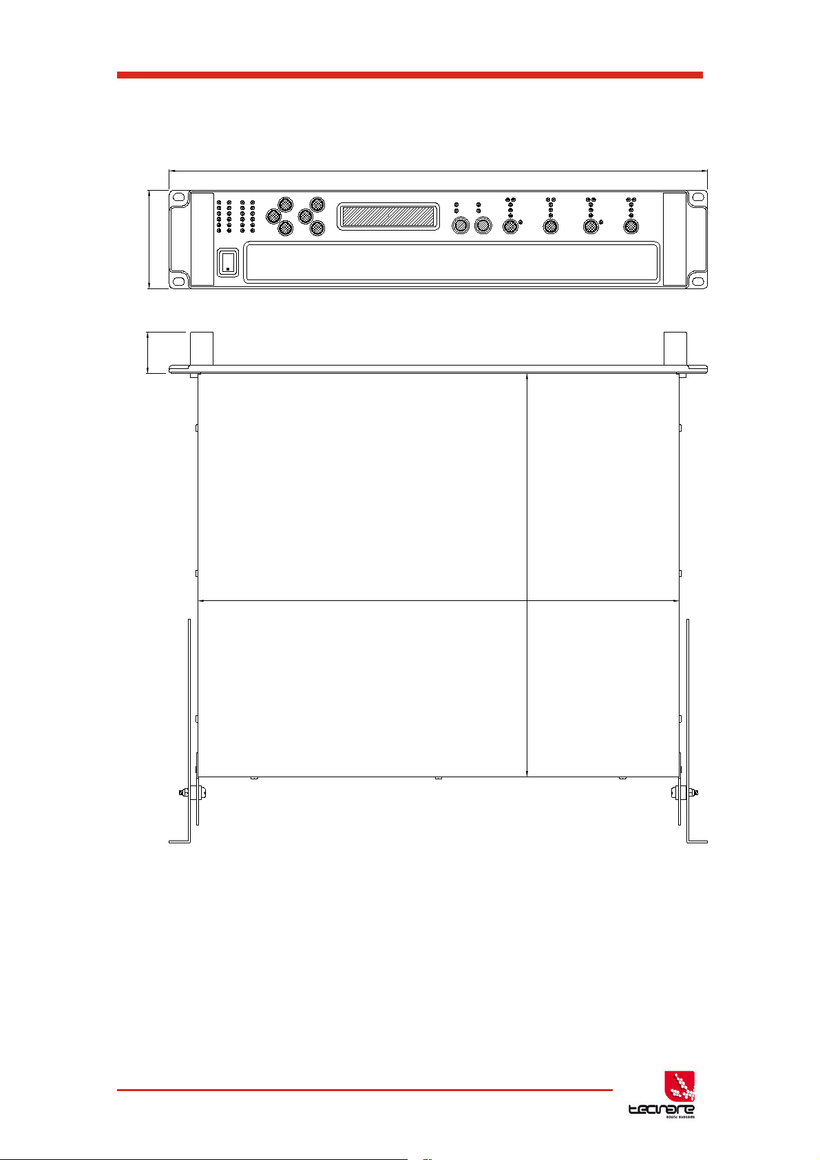
1.4 Mechanical installations
431
360
37
482
88
T-44/48 Series Operation Manual
Fig. 01: Amplifier dimensions
The T-44/48 Series Amplifier system is designed to be mounted in a standard 19” rack
enclosure.
Where the amplifier is used in a fixed installation, as long as the bottom unit is
supported and there are no gaps between units, it is acceptable to use only the front panel 19”
rack holes when fitting it in a standard rack enclosure. If the amplifier is mounted in a mobile
rack it is important that the rear is supported with a rear rack mounting kit (part number
TZA1182). Damage caused by insufficient support is not covered by the warranty.
9 T-44/48 Series | rev.
firm. 1.258 and above

T-44/48 Series Amplifier
To prevent damage to the front panel it is recommended that plastic cups or washers
are fitted underneath the rack mounting bolt heads.
It is possible to mount multiple T-44/48 Series amplifiers without ventilation gaps
between them but it is essential that an unobstructed flow of clean air is available from the front
of the unit to the rear. It is important that neither the air intakes on the front of the unit or the
exhaust vents at the rear are covered. Steps must be taken to ensure that hot air does not
continually circulate through the amplifiers from the back of the rack to the front.
The amplifier should never be exposed to rain or moisture during operation or storage. If
the unit does come into contact with moisture, remove the AC power cord immediately and
leave it in a dry and warm location to dry out.
Note that when any equipment is taken from a cold location into a hot humid one,
condensation may occur inside the device. Always allow time for the equipment to attain the
same temperature as its surrounding environment before connecting the AC power cord.
Operation Manual
1.5 AC Power Connection
The amplifier utilises a 32A Neutrik PowerCONTM type locking AC power connector. Use
only an AC power cord with a correctly terminated PowerCON
to make the connection to the mains power supply.
The amplifiers are designed to operate on 50/60 Hz AC power. The power supply sections
automatically configure themselves for either 115V or 230V nominal voltage at turn on. The
amplifiers will operate over an extended range of supply voltages (please refer to the technical
specifications).
Note that whilst the amplifier will operate correctly at voltages indicated, the specified output
power will only be achieved when operating with the stated nominal voltages.
TM
type (NAC3FC-HC) connector
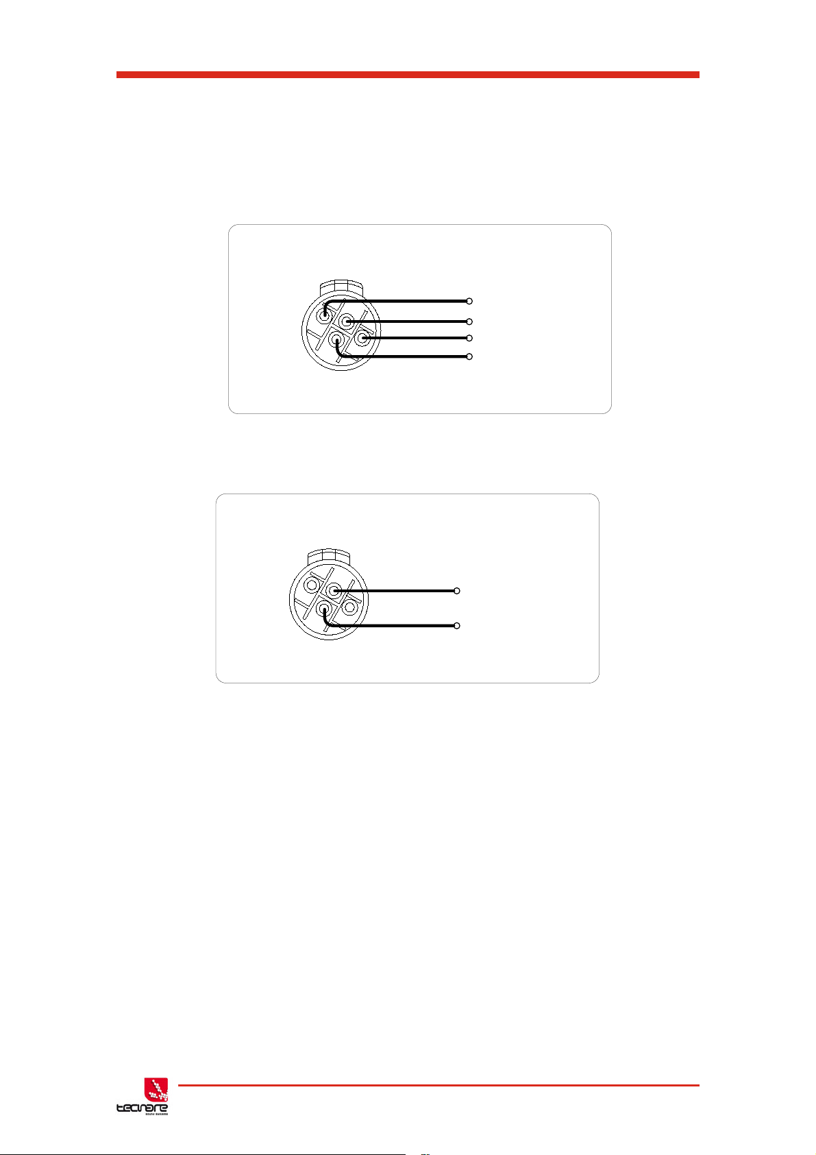
1.6 Audio Connections
1.6.1 Input Connections
For each input channel there is a female XLR-3 input connector. Even channel
numbers are for Analogue inputs only. Odd channel numbers are either for Analogue inputs
(when in Analogue input mode) or for AES3 input pairs (when in AES3 input mode).
• The HOT, + or ‘in phase’ connection should be made to pin 2 of the XLR
connector.
• The COLD, - or ‘out of phase’ connection should be made to pin 3 of the
XLR connector.
• Pin 1 of the XLR connectors is internally connected to the chassis.
The shield of the input cable should always be connected Pin 1 of the XLR to ensure
that EMC performance and regulations are met.
Fig. 02: Pin out assignment T-44 Analog Input/link
T-44/48 Series | rev.
firm. 1.258 and above
10

T-44/48 Series Operation Manual
Amplifier output connections
2+
1-
1+
2-
Speaker +
Speaker -
Digital LINK
Buffer
Digital INPUT
AES3
AES3 Inputs
A Latching XLR-3 connector accepts two channels of AES3 digital audio. Input
Impedance is 110 ohms; ensure that 110 ohm digital audio cable is used.
Fig. 03: Pin assignment T-44 Digital Input/Link
Fig. 04: Digital INPUT and LINK
Unbalanced connections
Please note that the use of unbalanced connections is not recommended,
however when connecting the amplifier to an unbalanced audio source, the signal
conductor should be connected to XLR pin2. The ‘Cold’ conductor or cable
screen should be connected to XLR pin 1 with a short connection made between
pin 1 and pin 3 as shown in Figure 3.
Fig.05: Balanced to Unbalanced Analog Wiring and Pin Out
1.6.2 Audio Output Connections
The amplifier is fitted with one Speakon
TM
NL4 connector per amplifier channel. The
appropriate conductor terminations are shown below and on the rear panel of the unit.
Fig. 06: Amplifier Output Normal connexion
11 T-44/48 Series | rev.
firm. 1.258 and above
T-44/48 Series Amplifier
Amplifier output connections – Bi Amp
2+
1-
1+
2-
Speaker1 +
Speaker1 -
Speaker2 +
Speaker2 -
Amplifier output connections – Bridge
2+
1-
1+
2-
Speaker +
Speaker -
and T-48
Operation Manual
The SpeakonTM NL4 connector for amplifier channel 1 carries the output for amplifier
channels 1 and 2. Similarly, the Speakon
TM
NL4 connector for amplifier channel 3 carries the
output for amplifier channels 3 and 4. This can be useful for making a connection to two
loudspeakers with one 4-core cable (i.e. Bi-Amp):
On the T-48 model, all output are Bi-Amp; each Speakon
TM
connector carries two amplifier
outputs – Channels 1&2, Channels 3&4, Channels 5&6 and Channels 7&8.
Fig. 07: Amplifier Output Bi-amp connexion (CH1 & CH3) and T-48 models
In addition, the channel 1 or channel 3 connector can also be used if the pair of amplifier
channels is being operated in bridged mode.
Each output of the device can be configured to drive either a low impedance load (LOW-Z),
or a Constant Voltage (CV) such as 25V LINE, 70V LINE or 100V LINE using the CV parameter
in the Output menu which determine the maximum RMS voltage that the amplifier will produce.
Select the one which is appropriate for the installation. A number of low impedance settings
(depending on the model) are also available. Although it is not critical that this setting matches
the impedance of the connected load, this will maximise the power that is available for the load.
Fig. 08: Amplifier Output Bridge connexion (CH1 & CH3)
1.6.3 Load Matching / 100/70/25V Line operation
T-44/48 Series | rev.
firm. 1.258 and above
12

T-44/48 Series Operation Manual
2 Introduction and Key Features
2.1 Introduction
The Tecnare T-44/48 Series Advanced System Amplifier represents current state-of-the-art
technology in several areas. This product is the result of several years of research, from which
many advances in switched mode power technologies and ever finer detail in signal processing
have stemmed. Taking advantage of the latest advances in analogue to digital conversion
technologies, the unit achieves performance levels among the very best that engineering
permits.
Below is a list of key features, followed by some information on the major advanced
features of the product.
2.2 Key Features
• Four channels of sonically pure Class D amplification
• Very high power density packs four channels and 20kW into just 2U of rack space
• Packed with robust protection and monitoring systems to keep the show going
• External Breaker Protection (EBP) limits the current draw to prevent breakers opening
• Linea Research minimal signal path design
• Class leading sonic performance achieved by the use of state of the art Amplifier
technologies and highly advanced DSP algorithms using Linea Micro Detail (LMD)
• 96 kHz sampling frequency provides for a nominally flat response beyond 40 kHz.
• Rotary encoders, illuminated buttons and graphical display provide a rapid, intuitive
and user-friendly control interface
• High speed Ethernet communications supporting DHCP, static-IP and auto-IP and
direct connection to a computer without the need for a router or a switch
• Powerful Drive Module concept, abstraction from device centric to speaker based
control
• Innovative Component Presets to allow individual outputs to be used for selected
drivers of a loudspeaker system
• Twelve layers of Parameter Overlays for trouble-free Grouping
• Unique VX limiter providing dynamic control for passive 2-way enclosures
• Unique LIR linear phase crossover shapes giving FIR-like performance without the
drawbacks
• Linear phase HF system EQ profiling which provides perfect integration between
enclosures
• Innovative excursion control limiter with sliding High Pass Filter; limits only the
damaging low frequencies
• Transducer thermal modelling provides regulation limiters, addressing long term
overload
13 T-44/48 Series | rev.
firm. 1.258 and above

T-44/48 Series Amplifier
Operation Manual
• Overshoot limiter governs amplitude of transient signals retaining average power
whilst constraining peak energy
• Dante audio networking with automatic fallover to Analogue or AES3
• AES3 inputs
2.3 Drive Modules
The 44/48 Series processor has a new way of ordering and grouping channels in order to
give a more speaker-based approach to controlling, designing and recalling speaker
configurations; these are called Drive Modules. A Drive Module is the Processing provided by
one Input DSP Block, and a number of Output DSP Blocks, which are associated with oneanother by means of routing. For example, if Input DSP Block B is routed to Outputs 3 and 4,
then this is a 2-way Drive Module with Input DSP Block B forming the ‘Master’ control, and
Output DSP Blocks 3 and 4 providing the driver-related control. Overall, this forms the
processing typically for one loudspeaker sub-system. The System Engineer Drive Module
control panel for this sub-system may then be used for control and monitoring of the associated
speaker.
Drive Modules may be included in Module Groups, which use the Parameter Overlay
feature in the Device to achieve trouble-free Grouping in the System Engineer application.
The Presets in the Device are Drive-Module centric, and are used to configure individual
Drive Modules rather than the whole device.
Importantly, Drive Modules move the focus away from the processing device, and onto the
loudspeaker systems.
A Drive Module Preset may be broken apart into Components, allowing any output to be
used for any component within a Drive Module Preset (i.e. any driver in a loudspeaker
subsystem).
Overview of Modules
See
2.4 Overlays
When the Device is used in Modules view in System Engineer, this allows the modules to
be grouped into Overlay Groups. These groups allow various Input (master) parameters to be
adjusted in all modules in that group, whist maintaining independent parameter values across
each group. This is achieved in the device by combining the parameters for all the layers for a
given section (Gain Delay, EQ etc.). When an Overlay parameter is active, the Overlay indicator
will become illuminated. The combined Gain or Delay etc. associated with a given section is
shown on the module panel in System Engineer, within square brackets [ ] under the Delay and
Gain for each input channel. The combined EQ curve is shown in an olive colour. The Input
Mute button in System Engineer will flash if an overlay mute is active. On the device, the
presence of an active overlay is generally indicated by square brackets “[]” after the parameter
value on the display.
An input overlay mute is indicated on the mute/clip indicator for that channel flashing. Note
that overlay parameters cannot be adjusted on the Device itself; these can only be controlled by
the System Engineer application. However, overlay parameters may be removed on the device
– see
carried in settings files.
Overlay Flush
page 37. Note that overlays are not stored in presets or snapshots or
T-44/48 Series | rev.
firm. 1.258 and above
14
T-44/48 Series Operation Manual
100 1.10
3
1.10
4
36
30
24
18
12
6
0
6
24dB/Oct
LIR (Linear Phase)
Frequency, Hz
Magnitude, dB
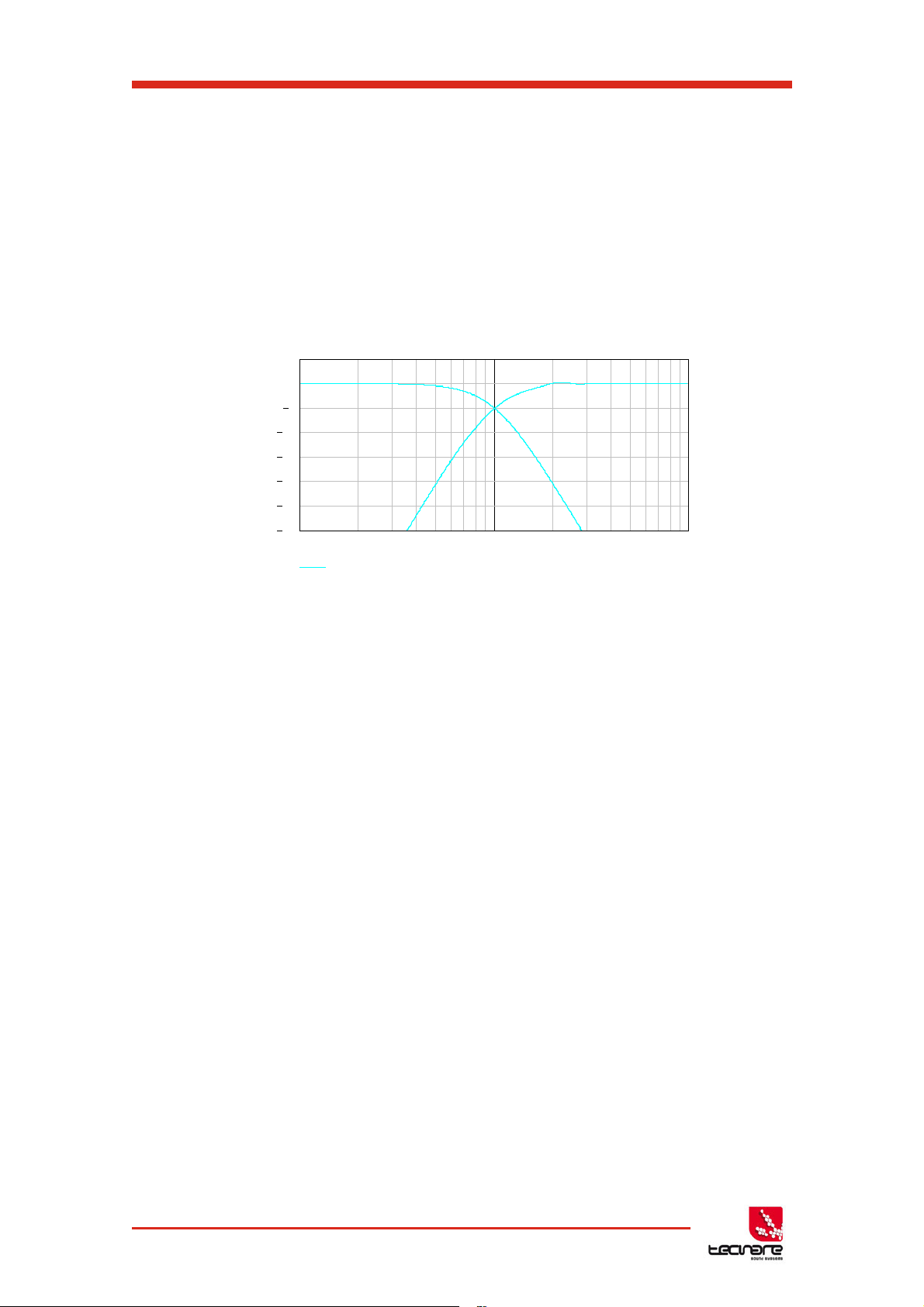
2.5 LIR Linear Phase Crossover Filtering
The T-44/48 Series also includes a new type of crossover filtering “Linea Impulse
Response” (LIR) crossover filtering, which gives a Linear Phase crossover that has a constant
delay regardless of frequency (unlike other types of crossover which delay different frequencies
to a different extent, thus smearing the arrival time). The LIR crossover can thus be described
as having a flat Group Delay response, and thus entirely free of Group Delay Distortion.
The shape of the LIR crossover filter is quite similar to a 4
filter, and maintains zero phase difference between the adjacent bands across the crossover
region to keep the polar response rock steady. See Figure 09.
th
order or 24dB/Oct Linkwitz-Riley
Figure 09: LIR Filter
2.6 FIR Linear Phase Equalisation
The Input High-Shelf Equalisers use Finite Impulse Response (FIR) filtering to produce
Linear Phase equalisation; that is all frequencies are delayed by the same amount, perfectly
preserving the transient response. This can also be important in applications where different
amounts of EQ are applied to different parts of a speaker cluster, such as to add 'Throw' EQ
boost so that parts of cluster which are throwing further can have HF absorption correction
added. If this EQ is not linear phase, then the zones where the speakers combine may suffer
frequency response anomalies.
15 T-44/48 Series | rev.
firm. 1.258 and above
T-44/48 Series Amplifier
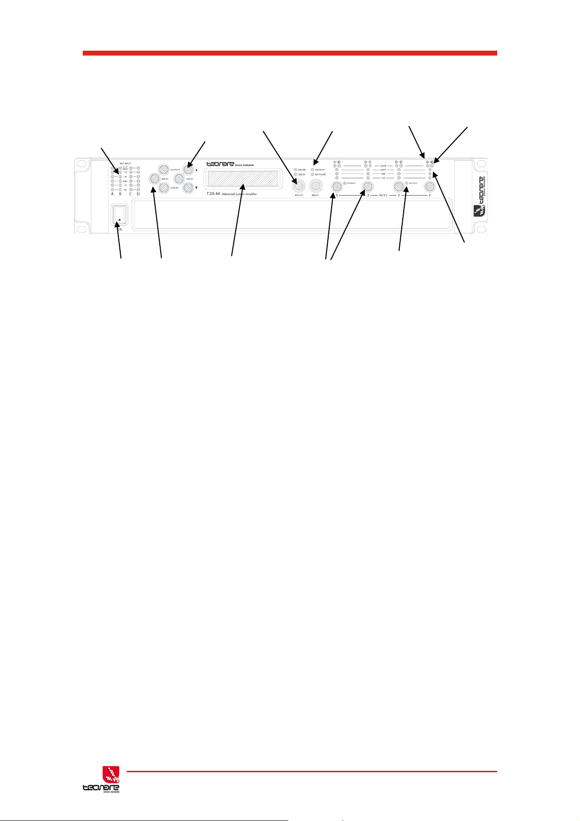
1- Input
Indicators
2 - Page
Buttons
4 – Status
3 – Parameter
Indicators
6 – Driver Indicators
12 – Limiters
5 – Amplifier
Indicators
7 – Power
8 – Menu
9 – Graphical
10 – Output
11 – Bridge
Operation Manual
3 Panels Interface User Guide
Signal
switch
Buttons
Selecti on
Encoders / Selection
display
Figure 10: Front panel schema
Mute Buttons
Indicators
Indicator
Indicator
3.1 Panel Layouts
The front panel of the Device of T-44 Series amplifiers is a combination of buttons together
with the LCD display allows the user access to detailed information and complete control over
the amplifier’s status. This chapter illustrates all the functions and settings accessible via the
amplifier front panel.
All the setup and setting functions described in this chapter can be also accessed via
computer with System Engineer
3.1.1 Front Panel
®
software.
Input Signal Indicators
A set of five indicators show “Sig”, “-12”, “0dBu”, “+6” and “+12” and “Clip (mute)” for each
of the DSP inputs “A” “B” “C” “D”. The signal present Indicators operate at approximately –40
dBu. The “0dBu” indicators are intended to show nominal operating level and can also be useful
for setting system gain structure. The Clip/mute Indicators- warn the user of input overload and
operate at 1dB before clip. This indicator also shows a muted input. Input mute is turned on/off
in the <INPUT/DSP> gain page. This indicator will also flash regularly if a Module Group has
muted this channel.
Page Selection Buttons
When one of the buttons <INPUT/DSP>, <OUTPUT> or <UTILITY> is illuminated, the up
<> and down <> arrows will also illuminate, informing the user that these buttons may be
used to scroll through the various pages of parameters that may be viewed and edited. The
<ENTER> button is used to confirm an operation such as storing or recalling a preset or
snapshot. It will illuminate when the user is being invited to press it. It will flash when warning
the user that pressing this button will activate an important function.
T-44/48 Series | rev.
firm. 1.258 and above
16

T-44/48 Series Operation Manual
Parameter Encoders
Two velocity sensitive parameter encoders are used to adjust parameters shown on the
display. Up to three parameters at a time are displayed on the screen. The parameter name is
shown above the parameter value in each of the three screen sections. Use SELECTS to
highlight the parameter, and then ADJUST to change it.
Status Indicators
The “OVERLAY” indicator shows when there are parameters activ e on a group layer, which
the user cannot access through the front panel of the device (see Overlay Flush). The
“NETAUDIO” indicator shows that a networked digital audio card is installed and routed (Such
as Dante™ or AVB™). The “ONLINE” indicator has three states:
Off: the unit is offline and not connected to a computer or network.
Flashing: the unit is searching for an IP address; if the unit does not find an IP address the unit
will assign itself an IP address automatically and the indicator will stop flashing.
On: the unit is online and connected with software. IP settings can be viewed or changed within
the <UTILITY> pages.
The AES3 IN indicator illuminates when one or more of the inputs is using an AES3 Source
Amplifier Indicators
This indicates when the amplifier protection systems are reducing the gain to keep the
parameters of the amplifier within specification, or that the channel is clipping.
Driver indicators
This indicates a signal 6dB higher than the limiter threshold, or when the threshold of the
excursion limiter has been exceeded, or when the thermal limiter is active, protecting against
long term thermal stress. Please note that because of the long release time of the thermal
limiter, this indicator may remain illuminated for several seconds after signal on that channel is
reduced.
Power Switch
Applies mains power to the device. If the device has entered Sleep mode, it may be woken
up again either from the System Engineer application, or by switching this switch off, then on
again.
Mute Buttons
There are three buttons to determine which section of the device to view or edit. The
<OUTPUT> button displays pages of parameters associated with a particular output channel.
The <INPUT/DSP> button displays pages of parameters associated with a particular input
socket or input DSP channel. Pressing <INPUT/DSP> or <OUTPUT> buttons repeatedly will
scroll through the inputs/outputs of the processor. After the last channel, navigation returns to
the Home screen. The <UTILITY> button displays pages of miscellaneous parameters not
associated with any particular channel. Whilst in Edit mode, one of these three buttons will be
illuminated. They are mutually exclusive – pressing one of the buttons will deselect any others
that are active. Pressing Utils will escape back to the Home screen.
Graphical Display
When the device is switched on, it will show the default screen. This provides a useful
overview of channel allocation and Drive Module presets.
17 T-44/48 Series | rev.
firm. 1.258 and above
 Loading...