

Tecnare Sound Systems T-48 Series, T-44 Series, T06-48, T10-48, T20-44 Operating Manual
...Page 1
Keep these important operating instructions.
Check www.tecnare.com for updates.
Operation Manual
DSP INPU T
CLIP
(mute)
+12
+6
OdBu
-12
SIG
ONLI NE
OUT PUT
INPU T ENT E R
DA B C
UTIL ITY
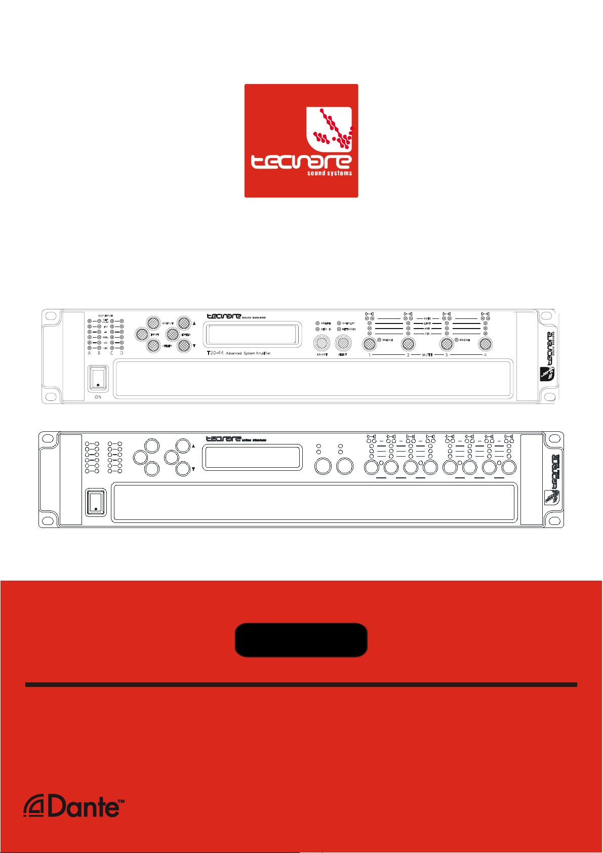
T2 0-4 4
Advanced System Amplifier
AES3 IN
SELECTADJU ST
OVE R LAY
NET AUDIO
BR IDG E
1 2
OVE R
LIMIT
-6dB
MUT E
SIG
BR IDG E
3
4
!
ON
S
U
U
S
P
N
P
P
T
N
I
I
T
D
D
P
C
C
I
P
P
I
L
L
(
(
)
)
e
u
u
t
t
e
m
m
1
+
+
1
2
2
6
6
+
+
OdBu
OdBu
1
2
2
1
-
-
G
S
S
G
I
I
C
C
B
D
D
B
A
A
O
O
N
N
U
O
O
U
U
U
T
P
T
T
P
T
U
U
T
P
T
I
I
N
P
N
R
R
E
E
N
T
T
N
E
E
U
U
I
L
T
T
Y
T
I
I
L
Y
T
I
8
0
0
-
1
4
4
-
T
T
Advanced System Amplifier
O
O
O
O
AES3
AES3IN
J
J
A
A
D
D
A
E
I
N
N
U
U
Y
L
E
L
A
Y
R
R
E
V
V
L
L
E
N
N
I
U
U
O
O
D
D
A
I
A4TTEENN
I
S
SELECT
SELECT
S
T
T
EEGGDDIIRRBB
2211
OO
RREEVV
TTIIMMIILL
dd66
BB
--
GGIISS
G
G
I
B E
B E
R
R
I
D
D
E
E
3
G
G
E
D
R
R
I
I
D
B
B
E
M
EETTUUM
5 86
G
G
D
R
D
I
I
R
B
B
7
Version 2 (Firm. 1.258 and above)
Available
T-44/48 Series
Advanced System Amplifier
Page 2

Page 3

T-44/48 Series Amplifier
Operation Manual
IMPORTANT SAFE INSTRUCTIONS
Before using the device, be sure to carefully read the Safe Instructions. Keep this document with the device all time.
1 Read these instructions.
2 Keep these instructions.
3 Heed all warnings.
4 Follow all instructions.
5 Do not use this apparatus near water.
6 Clean only with dry cloth.
15 Use the mains plug to disconnect the device
from mains.
16
17 Do not expose this equipment to dripping or
WARNING: To reduc e the risk of fire of
electric shock, do not expose this device to
rain or moisture.
splashing and ensure that no objects filled
with liquids, such as vases, are placed on
the equipment.
7 Do not block any ventilation openings. Install
in accordance with Exel Ac oustics’
instructions.
8 Do not install near any heat s ources such as
rad iators , heat registers, stoves or other
apparatus (including amplifiers) that produce
heat.
9 Do n ot def eat t he safety pu rp os e of the
polarized or grounding type plug. A polarized
plug has two blades with one wider than the
other. A grounding type plug had two blades
and a third grounding prong. The wide blade
or the third prong are provided f or your
safety. If the provided plug does not fit into
your outlet, consult an electrician for
replacement of the obsolete outlet.
10 Protect the power c ord from being walked on
or pinched particularly at plugs, convenienc e
receptacles and the point where they exit
from the appar atus.
11 Only use attachments / accessories
specified by the manufacturer.
12 Use only with the cart, tripod, bracket or
table specified by the manufacturer, or sold
with the apparatus. W hen a cart is used, use
caution when moving the cart / apparatus
combination to avoid injury from tip-over.
18 The mains plug of the power supply c ord
shall remain readily operable.
19 Do not connect the unit’s output to any other
voltage source, such as battery, mains
source, or power supply, r egardless of
whether the unit is turned on or off.
20 Do not remove the top (or bottom) c over.
Removal of the cover will expose hazardous
voltages. There are no user serviceable part
inside and removal may void warranty.
21 If the equipment is used in a manner not
specified by the Exel Acoustic, the protection
by the equipment may be impaired.
13 Unplug this apparatus during lightning
storms or when unused for long periods of
time.
14 Refer all servicing to qualified service
personnel. Service is required when the
apparatus has been damaged in any way,
such as power-supply cord or plug
damaged, liquid has been spilled or objects
have fallen into the apparatus, this
apparatus has been exposed to r ain or
moisture, does not operate normally, or has
been dropped.
T-44/48 Series | rev.
firm. 1.258 and above
2
Page 4
Dangerous voltages; risk of
electrical shock
Important operating
instructions
Pour indiquer les risques
dangereuses
Wichtige Betriebsanweisung
sanleitung
Presencia de voltajes
peligrosos
Importantes instrucciones
operativas
SYMBOLS USED
T-44/48 Series Operation Manual
resultant de tensions
Warnung vor gefährlicher
elektrischer Spannung
Pour indequer important
Instructions
oder Gebrauchsanleitung
Frame or chassis Protective earth ground
Masse, chassis Terre de protection
Rahmen oder Gehäuse Masse Schutzleiter
Masa o chasis Puesta a tierra
SAFETY WARNING
Permanent disconnection from the mains supply is to be achieved by removing the supplied
cord connector from the back of the unit.
Do not remove any covers, loosen any fixings or allow items to enter any aperture.
Objects filled with liquids should not be placed on this apparatus.
Replace the mains fuse only with a fuse of the same type
The rear of the product may get hot. Avoid direct skin contact during operation and for at least 5
minutes after power has been isolated.
AVERTISSEMENT DE SECURITE
Pour déconnecter l'appareil de l'alimentation principale de façon permanente, débranchez le
connecteur du câble fourni à l'arrière de l'appareil.
Ne retirez pas les couvercles, ne desserrez pas les fixations et ne laissez aucune pièce
s'introduire dans les ouvertures.
Ne placez pas d'objets contenant du liquide à proximité de l'appareil.
Ne remplacez le fusible de réseau principal que par un fusible du même type.
Le radiateur arrière de cet appareil devient chaud. Evitez tout contact direct avec la peau
pendant le fonctionnement et au moins 5 minutes après la mise hors tension de l'appareil.
3 T-44/48 Series | rev.
firm. 1.258 and above
Page 5

T-44/48 Series Amplifier
PRECAUCIONES DE SEGURIDAD
Para la desconexión permanente de la red eléctrica es necesaria la desconexión del cable
suministrado de la parte posterior de la unidad
No retire ninguna cubierta ni afloje tornillos. No permita que entre nada en el interior del
dispositivo.
No coloque sobre él objetos que contengan líquidos ni lo exponga a la lluvia o humedad.
Reemplazar el fusible principal sólo por un fusible del mismo tipo.
La parte posterior del dispositivo puede calentarse. Evite el contacto directo con la piel durante
el funcionamiento del dispositivo y durante, al menos, 5 minutos después de la desconexión
eléctrica.
Operation Manual
STANDARDS
FOR CUSTOMERS IN EUROPE
This product complies with both the LVD (electrical safety) 73/23/EEC and EMC
(electromagnetic compatibility) 89/336/EEC directives issues by the commission
of the European community.
Compliance with these directives implies conformity with the following European standards:
EN60065 Product safety
EN55103-1 EMC emissions
EN55103-2 EMC immunity
This product is intended for the following electromagnetic environments: E1, E2; E3 & E4.
THIS PRODUCT MUST BE EARTHED. Use only a flexible cable or cord with a green and
yellow core which must be connected to the protective earthing terminal of a suitable mains plug
or the earthing terminal of the installation. The cord must be a maximum of 2m long, have a
2.5mm
THIS PRODUCT IS DESIGNED FOR PERMANENT INSTALLATION. It must be fitted in to a
19” rack enclosure and not operated unless so installed. The rack enclosure should be open at
the front and back to allow free ventilation and movement of air through the product.
FOR CUSTOMERS IN THE USA
This product has been tested for electrical safety and complies with:
UL60065 7th edition
THIS PRODUCT MUST BE EARTHED. Use only a flexible cable or cord with a green or green /
yellow core which must be connected to the protective earthing terminal of a suitable mains plug
or the earthing terminal of the installation. The cord must be a maximum of 6’ long, be 14AWG,
have a rating SJ, SJT, SJE or 300/500V H05W-F and be marked VW-1.
THIS PRODUCT IS DESIGNED FOR PERMANENT INSTALLATION. It must be fitted in to a
19” rack enclosure and not operated unless so installed. The rack enclosure should be open at
the front and back to allow free ventilation and movement of air through the product.
2
CSA, a 300/500V rating and comply with EN50525-2-11 / H05W-F.
T-44/48 Series | rev.
firm. 1.258 and above
4
Page 6

T-44/48 Series Operation Manual
FOR CUSTOMERS IN CANADA
This product complies with CA /CSA C22.2 No.60065-03
Ce produit est conforme avec CA /CSA C22.2 No.60065-03
THIS PRODUCT MUST BE EARTHED. Use only a flexible cable or cord with a green or green /
yellow core which must be connected to the protective earthing terminal of a suitable mains plug
or the earthing terminal of the installation. The cord must be a maximum of 6’ long, be 14AWG,
have a rating SJ, SJT, SJE or 300/500V H05W-F and be marked VW-1.
CE PRODUIT DOIT ÊTRE MIS À LA TERRE. Utilisez uniquement un câble souple avec un
noyau vert ou vert / jaune qui doit être relié à la borne de terre de connecteur d'alimentation ou
la borne de terre de l'installation. Le cordon doit être un maximum de 6' (2m) de long, 14 AWG
(2.5mm
2
CSA), être classé SJ, SJT, SJE ou 300/500V H05W-F et être marquée VW-1
THIS PRODUCT IS DESIGNED FOR PERMANENT INSTALLATION. It must be fitted in to a
19” rack enclosure and not operated unless so installed. The rack enclosure should be open at
the front and back to allow free ventilation and movement of air through the product.
CE PRODUIT EST CONÇU POUR UNE INSTALLATION PERMANENTE. Il doit être installé
dans un boîtier rack 19 ". Le rack devrait être ouvert à l'avant et l'arrière pour permettre la
ventilation et le mouvement d'air libre à travers le produit .
DECLARATION OF CONFORMITY WITH CANADIAN ICES-003
This Class B digital apparatus complies with Canadian ICES-003.
Cet appareil numérique de la classe B est conforme à la norme NMB-003 du Canada.
FEDERAL COMMUNICATIONS COMMISSION NOTICE
An example of this equipment has been tested and found to comply with the limits for a Class B
digital device, pursuant to Part 15 of the FCC Rules. These limits are designed to provide
reasonable protection against harmful interference in a residential and commercial installation.
This equipment generates, uses, and can radiate radio frequency energy, and if not installed
and used in accordance with the instructions, may cause harmful interference to radio
communications. However, there is no guarantee that interference will not occur in a particular
installation. If this equipment does cause harmful interference to radio or television reception,
which can be determined by turning the equipment off and on, the user is encouraged to try and
correct the interference by one or more of the following measures:
• Reorient or relocate the receiving antenna.
• Increase the distance between the equipment and the receiver.
• Connect the equipment to an outlet on a circuit different from that to which the receiver
is connected.
• Consult the dealer or an experienced radio/TV technician for help.
FCC Caution: Any changes or modifications not expressly approved by the party responsible
for compliance could void the user’s authority to operate this equipment.
5 T-44/48 Series | rev.
firm. 1.258 and above
Page 7

T-44/48 Series Amplifier
Operation Manual
DECLARACIÓN DE CONFORMIDAD
DECLARATION OF CONFORMITY
EXEL ACOUSTICS SL
CL Encinar, 282. Polígono Industrial Monte Boyal. 45950 – Casarrubios del Monte (Toledo),
España (Spain).
Declara que el producto T-44/48 Series y sus respectivas opciones, cumple con la parte 15 de
las reglas de la FCC.
Declare under our sole responsibility that devices in the T-44/48 Series range of products,
comply with Part 15 of the FCC Rules.
La operación está sujeta a las siguientes dos condiciones
(1) Este dispositivo no puede causar interferencias perjudiciales y
(2) este dispositivo debe aceptar cualquier interferencia recibida, incluidas las
interferencias que puedan provocar un funcionamiento no deseado.
Operation is subject to the following two conditions:
(1) This device may not cause harmful interference, and
(2) this device must accept any interference received, including interference that
may cause undesired operation.
T-44/48 Series | rev.
firm. 1.258 and above
6
Page 8

T-44/48 Series Operation Manual
Table of Contents
IMPORTANT SAFE INSTRUCTIONS...................................................................................... 2
DECLARACIÓN DE CONFORMIDAD ..................................................................................... 6
1 Welcome and Installations instructions ...................................................................... 8
1.1 Thanks and unpacking ............................................................................................. 8
1.2 Unpacking ................................................................................................................ 8
1.3 The User Guide ........................................................................................................ 8
1.4 Mechanical installations ............................................................................................ 9
1.5 AC Power Connection ............................................................................................ 10
1.6 Audio Connections ................................................................................................. 10
2 Introduction and Key Features .................................................................................. 13
2.1 Introduction ............................................................................................................ 13
2.2 Key Features .......................................................................................................... 13
2.3 Drive Modules ........................................................................................................ 14
2.4 Overlays ................................................................................................................. 14
2.5 LIR Linear Phase Crossover Filtering ..................................................................... 15
2.6 FIR Linear Phase Equalisation ............................................................................... 15
3 Panels Interface User Guide ....................................................................................... 16
3.1 Panel Layouts ........................................................................................................ 16
4 Operation modes ......................................................................................................... 20
4.2 Input ....................................................................................................................... 26
4.3 Output .................................................................................................................... 29
4.4 Utility Page ............................................................................................................. 33
5 Hardware Function....................................................................................................... 35
5.1 Snapshots .............................................................................................................. 35
5.2 Aux Port ................................................................................................................. 35
5.3 Latency Delay ........................................................................................................ 36
5.4 Secure Mode .......................................................................................................... 37
5.5 Overlay Flush ......................................................................................................... 37
5.6 Revert to Factory Settings ...................................................................................... 37
5.7 Protection Systems ................................................................................................ 38
6 Remote control and System Engineer® Processing ................................................ 40
6.1 Quick Start Guide ................................................................................................... 40
6.2 Remote Control setup ............................................................................................. 41
7 Technical Specifications .............................................................................................. 46
7.1 Processing Block Diagram ...................................................................................... 50
8 EQ and Filter Response Graphs ................................................................................. 51
7 T-44/48 Series | rev.
firm. 1.258 and above
Page 9

T-44/48 Series Amplifier
Operation Manual
1 Welcome and Installations instructions
1.1 Thanks and unpacking
Thank you for choosing a Tecnare T-44/48 Series Advanced System Amplifier for your
application. Please spare a little time to study the contents of this manual, so that you obtain the
best possible performance from this unit.
Please spare a little time to study the contents of this manual, so that you obtain the best
possible performance from this unit. Control and editing features are accessible via the front
panel interface or via the included System Engineer software.
All Tecnare
If you would like further information about this or any other Tecnare
contact us. We look forward to helping you in the near future.
Information and specifications are subject to change. Updates and supplementary
information are available on the Tecnare
http://www.tecnare.com
Tecnare Technical Support is available at:
• (T): +34 918 170 110 - +34 918 171 001
• (e-mail): tecnare@tecnare.com
Thank you again for placing your confidence in Tecnare
®
products are carefully engineered for world-class performance and reliability.
®
product, please
®
website:
®
products.
1.2 Unpacking
After unpacking the unit please check carefully for any damage to the device or the supplied
accessories. Every Tecnare product is tested and inspected before leaving the factory and
should arrive in perfect condition. If damage is found, please notify the carrier concerned at
once. You, the consignee, must instigate any claim. Please retain all packaging in case of future
re-shipment.
1.3 The User Guide
This user manual gives a progressively more detailed description of the functions of the
Tecnare T-44/48 Series Advanced System Amplifier. A pages quick reference guide is provided
for those users who are experienced with this type of equipment and just need to know how to
‘drive’ the front panel. A detailed explanation of the front and rear panel controls and indicators
is contained in the next section.
The final section describes each individual function or feature with annotated images
explaining its use. Where appropriate, the graphical display is shown to further elaborate on the
units operation.
To complete the manual a reference section is included, describing the technical
performance and Mechanical drawing of the device complete with graphs of filter responses.
T-44/48 Series | rev.
firm. 1.258 and above
8
Page 10
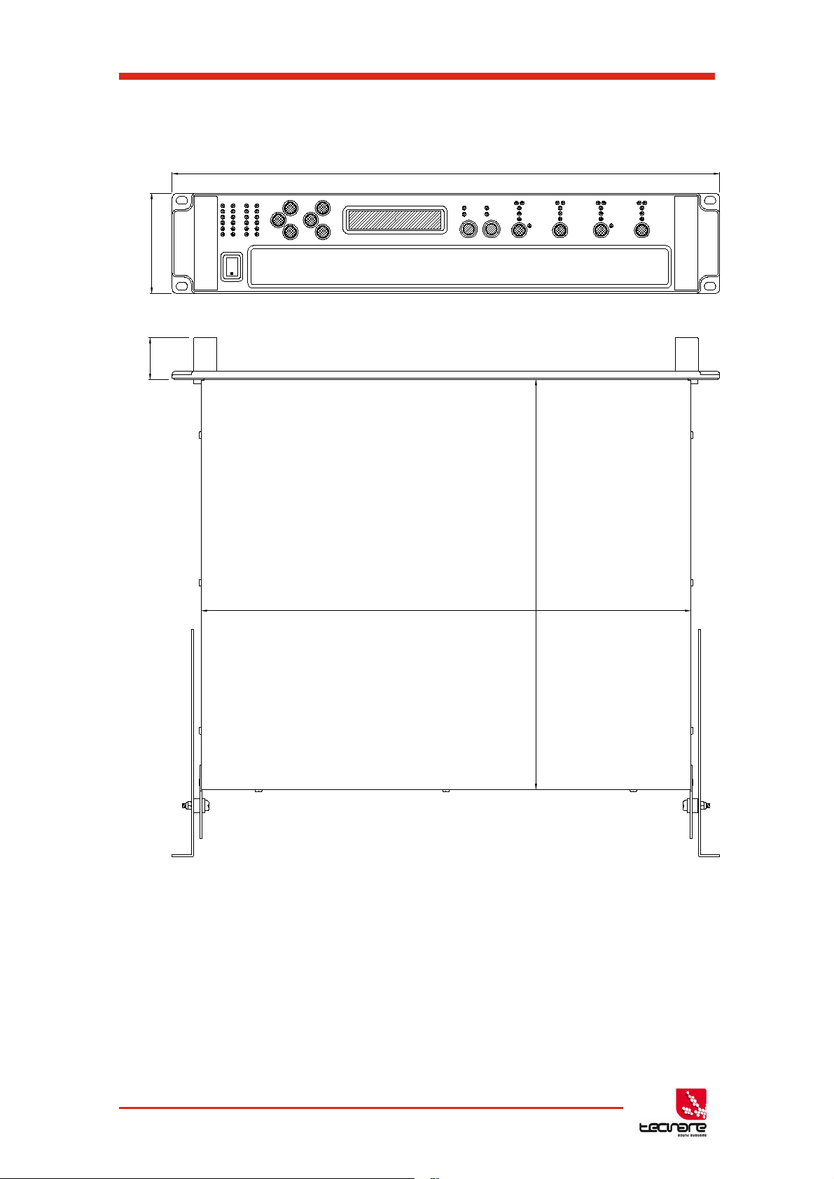
1.4 Mechanical installations
431
360
37
482
88
T-44/48 Series Operation Manual
Fig. 01: Amplifier dimensions
The T-44/48 Series Amplifier system is designed to be mounted in a standard 19” rack
enclosure.
Where the amplifier is used in a fixed installation, as long as the bottom unit is
supported and there are no gaps between units, it is acceptable to use only the front panel 19”
rack holes when fitting it in a standard rack enclosure. If the amplifier is mounted in a mobile
rack it is important that the rear is supported with a rear rack mounting kit (part number
TZA1182). Damage caused by insufficient support is not covered by the warranty.
9 T-44/48 Series | rev.
firm. 1.258 and above
Page 11

T-44/48 Series Amplifier
To prevent damage to the front panel it is recommended that plastic cups or washers
are fitted underneath the rack mounting bolt heads.
It is possible to mount multiple T-44/48 Series amplifiers without ventilation gaps
between them but it is essential that an unobstructed flow of clean air is available from the front
of the unit to the rear. It is important that neither the air intakes on the front of the unit or the
exhaust vents at the rear are covered. Steps must be taken to ensure that hot air does not
continually circulate through the amplifiers from the back of the rack to the front.
The amplifier should never be exposed to rain or moisture during operation or storage. If
the unit does come into contact with moisture, remove the AC power cord immediately and
leave it in a dry and warm location to dry out.
Note that when any equipment is taken from a cold location into a hot humid one,
condensation may occur inside the device. Always allow time for the equipment to attain the
same temperature as its surrounding environment before connecting the AC power cord.
Operation Manual
1.5 AC Power Connection
The amplifier utilises a 32A Neutrik PowerCONTM type locking AC power connector. Use
only an AC power cord with a correctly terminated PowerCON
to make the connection to the mains power supply.
The amplifiers are designed to operate on 50/60 Hz AC power. The power supply sections
automatically configure themselves for either 115V or 230V nominal voltage at turn on. The
amplifiers will operate over an extended range of supply voltages (please refer to the technical
specifications).
Note that whilst the amplifier will operate correctly at voltages indicated, the specified output
power will only be achieved when operating with the stated nominal voltages.
TM
type (NAC3FC-HC) connector
1.6 Audio Connections
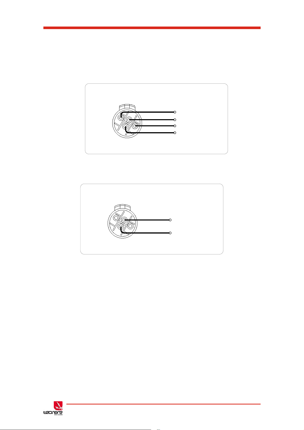
1.6.1 Input Connections
For each input channel there is a female XLR-3 input connector. Even channel
numbers are for Analogue inputs only. Odd channel numbers are either for Analogue inputs
(when in Analogue input mode) or for AES3 input pairs (when in AES3 input mode).
• The HOT, + or ‘in phase’ connection should be made to pin 2 of the XLR
connector.
• The COLD, - or ‘out of phase’ connection should be made to pin 3 of the
XLR connector.
• Pin 1 of the XLR connectors is internally connected to the chassis.
The shield of the input cable should always be connected Pin 1 of the XLR to ensure
that EMC performance and regulations are met.
Fig. 02: Pin out assignment T-44 Analog Input/link
T-44/48 Series | rev.
firm. 1.258 and above
10
Page 12

T-44/48 Series Operation Manual
Amplifier output connections
2+
1-
1+
2-
Speaker +
Speaker -
Digital LINK
Buffer
Digital INPUT
AES3
AES3 Inputs
A Latching XLR-3 connector accepts two channels of AES3 digital audio. Input
Impedance is 110 ohms; ensure that 110 ohm digital audio cable is used.
Fig. 03: Pin assignment T-44 Digital Input/Link
Fig. 04: Digital INPUT and LINK
Unbalanced connections
Please note that the use of unbalanced connections is not recommended,
however when connecting the amplifier to an unbalanced audio source, the signal
conductor should be connected to XLR pin2. The ‘Cold’ conductor or cable
screen should be connected to XLR pin 1 with a short connection made between
pin 1 and pin 3 as shown in Figure 3.
Fig.05: Balanced to Unbalanced Analog Wiring and Pin Out
1.6.2 Audio Output Connections
The amplifier is fitted with one Speakon
TM
NL4 connector per amplifier channel. The
appropriate conductor terminations are shown below and on the rear panel of the unit.
Fig. 06: Amplifier Output Normal connexion
11 T-44/48 Series | rev.
firm. 1.258 and above
Page 13
T-44/48 Series Amplifier
Amplifier output connections – Bi Amp
2+
1-
1+
2-
Speaker1 +
Speaker1 -
Speaker2 +
Speaker2 -
Amplifier output connections – Bridge
2+
1-
1+
2-
Speaker +
Speaker -
and T-48
Operation Manual
The SpeakonTM NL4 connector for amplifier channel 1 carries the output for amplifier
channels 1 and 2. Similarly, the Speakon
TM
NL4 connector for amplifier channel 3 carries the
output for amplifier channels 3 and 4. This can be useful for making a connection to two
loudspeakers with one 4-core cable (i.e. Bi-Amp):
On the T-48 model, all output are Bi-Amp; each Speakon
TM
connector carries two amplifier
outputs – Channels 1&2, Channels 3&4, Channels 5&6 and Channels 7&8.
Fig. 07: Amplifier Output Bi-amp connexion (CH1 & CH3) and T-48 models
In addition, the channel 1 or channel 3 connector can also be used if the pair of amplifier
channels is being operated in bridged mode.
Each output of the device can be configured to drive either a low impedance load (LOW-Z),
or a Constant Voltage (CV) such as 25V LINE, 70V LINE or 100V LINE using the CV parameter
in the Output menu which determine the maximum RMS voltage that the amplifier will produce.
Select the one which is appropriate for the installation. A number of low impedance settings
(depending on the model) are also available. Although it is not critical that this setting matches
the impedance of the connected load, this will maximise the power that is available for the load.
Fig. 08: Amplifier Output Bridge connexion (CH1 & CH3)
1.6.3 Load Matching / 100/70/25V Line operation
T-44/48 Series | rev.
firm. 1.258 and above
12
Page 14

T-44/48 Series Operation Manual
2 Introduction and Key Features
2.1 Introduction
The Tecnare T-44/48 Series Advanced System Amplifier represents current state-of-the-art
technology in several areas. This product is the result of several years of research, from which
many advances in switched mode power technologies and ever finer detail in signal processing
have stemmed. Taking advantage of the latest advances in analogue to digital conversion
technologies, the unit achieves performance levels among the very best that engineering
permits.
Below is a list of key features, followed by some information on the major advanced
features of the product.
2.2 Key Features
• Four channels of sonically pure Class D amplification
• Very high power density packs four channels and 20kW into just 2U of rack space
• Packed with robust protection and monitoring systems to keep the show going
• External Breaker Protection (EBP) limits the current draw to prevent breakers opening
• Linea Research minimal signal path design
• Class leading sonic performance achieved by the use of state of the art Amplifier
technologies and highly advanced DSP algorithms using Linea Micro Detail (LMD)
• 96 kHz sampling frequency provides for a nominally flat response beyond 40 kHz.
• Rotary encoders, illuminated buttons and graphical display provide a rapid, intuitive
and user-friendly control interface
• High speed Ethernet communications supporting DHCP, static-IP and auto-IP and
direct connection to a computer without the need for a router or a switch
• Powerful Drive Module concept, abstraction from device centric to speaker based
control
• Innovative Component Presets to allow individual outputs to be used for selected
drivers of a loudspeaker system
• Twelve layers of Parameter Overlays for trouble-free Grouping
• Unique VX limiter providing dynamic control for passive 2-way enclosures
• Unique LIR linear phase crossover shapes giving FIR-like performance without the
drawbacks
• Linear phase HF system EQ profiling which provides perfect integration between
enclosures
• Innovative excursion control limiter with sliding High Pass Filter; limits only the
damaging low frequencies
• Transducer thermal modelling provides regulation limiters, addressing long term
overload
13 T-44/48 Series | rev.
firm. 1.258 and above
Page 15

T-44/48 Series Amplifier
Operation Manual
• Overshoot limiter governs amplitude of transient signals retaining average power
whilst constraining peak energy
• Dante audio networking with automatic fallover to Analogue or AES3
• AES3 inputs
2.3 Drive Modules
The 44/48 Series processor has a new way of ordering and grouping channels in order to
give a more speaker-based approach to controlling, designing and recalling speaker
configurations; these are called Drive Modules. A Drive Module is the Processing provided by
one Input DSP Block, and a number of Output DSP Blocks, which are associated with oneanother by means of routing. For example, if Input DSP Block B is routed to Outputs 3 and 4,
then this is a 2-way Drive Module with Input DSP Block B forming the ‘Master’ control, and
Output DSP Blocks 3 and 4 providing the driver-related control. Overall, this forms the
processing typically for one loudspeaker sub-system. The System Engineer Drive Module
control panel for this sub-system may then be used for control and monitoring of the associated
speaker.
Drive Modules may be included in Module Groups, which use the Parameter Overlay
feature in the Device to achieve trouble-free Grouping in the System Engineer application.
The Presets in the Device are Drive-Module centric, and are used to configure individual
Drive Modules rather than the whole device.
Importantly, Drive Modules move the focus away from the processing device, and onto the
loudspeaker systems.
A Drive Module Preset may be broken apart into Components, allowing any output to be
used for any component within a Drive Module Preset (i.e. any driver in a loudspeaker
subsystem).
Overview of Modules
See
2.4 Overlays
When the Device is used in Modules view in System Engineer, this allows the modules to
be grouped into Overlay Groups. These groups allow various Input (master) parameters to be
adjusted in all modules in that group, whist maintaining independent parameter values across
each group. This is achieved in the device by combining the parameters for all the layers for a
given section (Gain Delay, EQ etc.). When an Overlay parameter is active, the Overlay indicator
will become illuminated. The combined Gain or Delay etc. associated with a given section is
shown on the module panel in System Engineer, within square brackets [ ] under the Delay and
Gain for each input channel. The combined EQ curve is shown in an olive colour. The Input
Mute button in System Engineer will flash if an overlay mute is active. On the device, the
presence of an active overlay is generally indicated by square brackets “[]” after the parameter
value on the display.
An input overlay mute is indicated on the mute/clip indicator for that channel flashing. Note
that overlay parameters cannot be adjusted on the Device itself; these can only be controlled by
the System Engineer application. However, overlay parameters may be removed on the device
– see
carried in settings files.
Overlay Flush
page 37. Note that overlays are not stored in presets or snapshots or
T-44/48 Series | rev.
firm. 1.258 and above
14
Page 16
T-44/48 Series Operation Manual
100 1.10
3
1.10
4
36
30
24
18
12
6
0
6
24dB/Oct
LIR (Linear Phase)
Frequency, Hz
Magnitude, dB
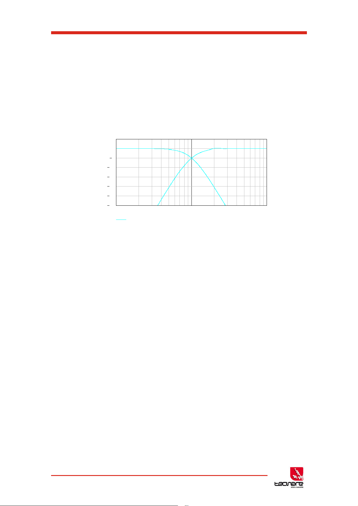
2.5 LIR Linear Phase Crossover Filtering
The T-44/48 Series also includes a new type of crossover filtering “Linea Impulse
Response” (LIR) crossover filtering, which gives a Linear Phase crossover that has a constant
delay regardless of frequency (unlike other types of crossover which delay different frequencies
to a different extent, thus smearing the arrival time). The LIR crossover can thus be described
as having a flat Group Delay response, and thus entirely free of Group Delay Distortion.
The shape of the LIR crossover filter is quite similar to a 4
filter, and maintains zero phase difference between the adjacent bands across the crossover
region to keep the polar response rock steady. See Figure 09.
th
order or 24dB/Oct Linkwitz-Riley
Figure 09: LIR Filter
2.6 FIR Linear Phase Equalisation
The Input High-Shelf Equalisers use Finite Impulse Response (FIR) filtering to produce
Linear Phase equalisation; that is all frequencies are delayed by the same amount, perfectly
preserving the transient response. This can also be important in applications where different
amounts of EQ are applied to different parts of a speaker cluster, such as to add 'Throw' EQ
boost so that parts of cluster which are throwing further can have HF absorption correction
added. If this EQ is not linear phase, then the zones where the speakers combine may suffer
frequency response anomalies.
15 T-44/48 Series | rev.
firm. 1.258 and above
Page 17
T-44/48 Series Amplifier
1- Input
Indicators
2 - Page
Buttons
4 – Status
3 – Parameter
Indicators
6 – Driver Indicators
12 – Limiters
5 – Amplifier
Indicators
7 – Power
8 – Menu
9 – Graphical
10 – Output
11 – Bridge
Operation Manual
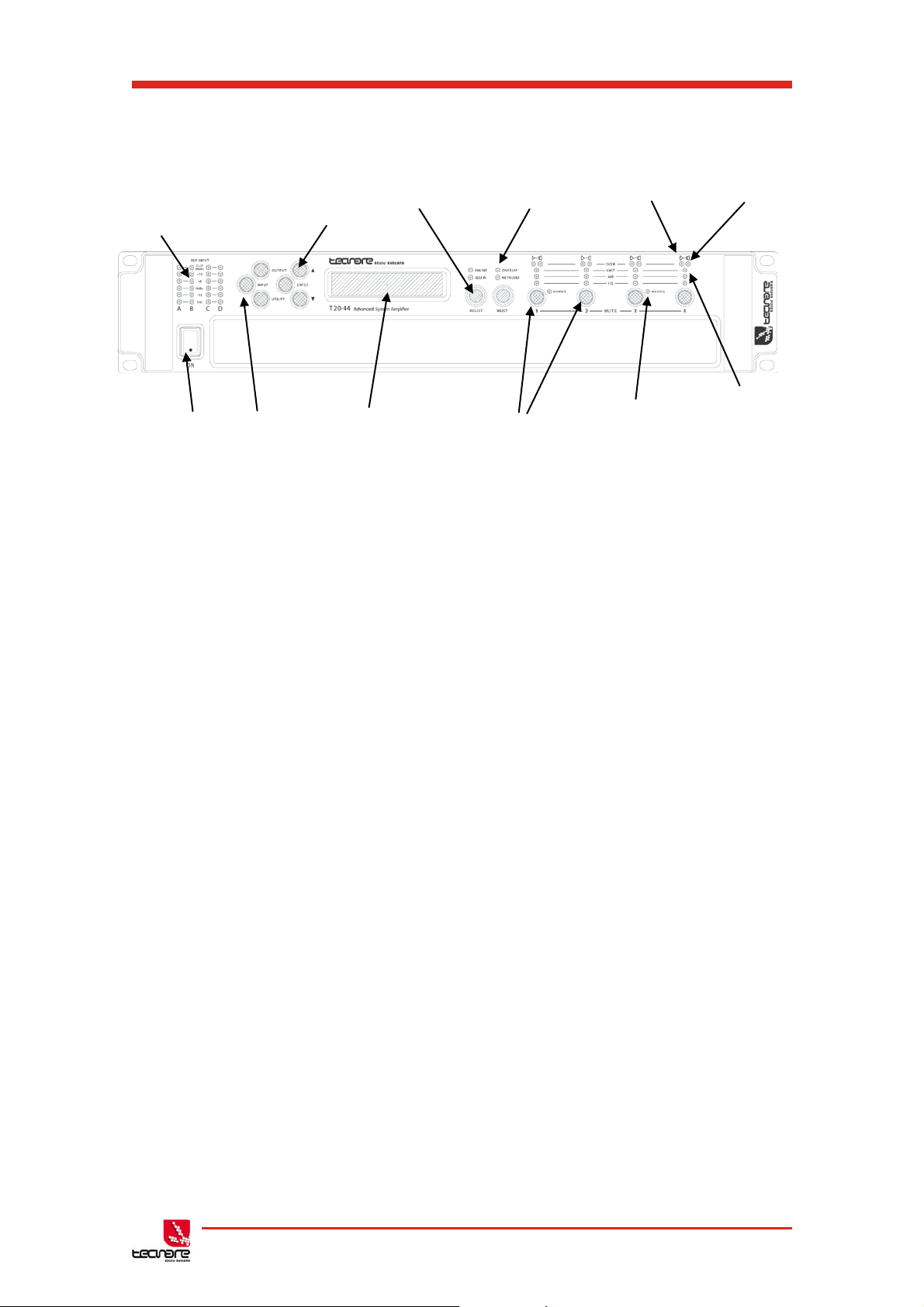
3 Panels Interface User Guide
Signal
switch
Buttons
Selecti on
Encoders / Selection
display
Figure 10: Front panel schema
Mute Buttons
Indicators
Indicator
Indicator
3.1 Panel Layouts
The front panel of the Device of T-44 Series amplifiers is a combination of buttons together
with the LCD display allows the user access to detailed information and complete control over
the amplifier’s status. This chapter illustrates all the functions and settings accessible via the
amplifier front panel.
All the setup and setting functions described in this chapter can be also accessed via
computer with System Engineer
3.1.1 Front Panel
®
software.
Input Signal Indicators
A set of five indicators show “Sig”, “-12”, “0dBu”, “+6” and “+12” and “Clip (mute)” for each
of the DSP inputs “A” “B” “C” “D”. The signal present Indicators operate at approximately –40
dBu. The “0dBu” indicators are intended to show nominal operating level and can also be useful
for setting system gain structure. The Clip/mute Indicators- warn the user of input overload and
operate at 1dB before clip. This indicator also shows a muted input. Input mute is turned on/off
in the <INPUT/DSP> gain page. This indicator will also flash regularly if a Module Group has
muted this channel.
Page Selection Buttons
When one of the buttons <INPUT/DSP>, <OUTPUT> or <UTILITY> is illuminated, the up
<> and down <> arrows will also illuminate, informing the user that these buttons may be
used to scroll through the various pages of parameters that may be viewed and edited. The
<ENTER> button is used to confirm an operation such as storing or recalling a preset or
snapshot. It will illuminate when the user is being invited to press it. It will flash when warning
the user that pressing this button will activate an important function.
T-44/48 Series | rev.
firm. 1.258 and above
16
Page 18

T-44/48 Series Operation Manual
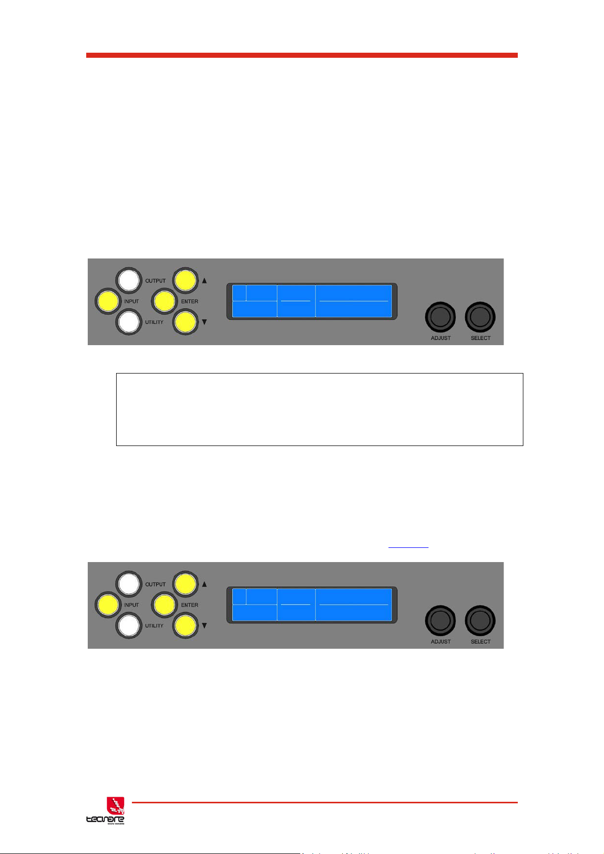
Parameter Encoders
Two velocity sensitive parameter encoders are used to adjust parameters shown on the
display. Up to three parameters at a time are displayed on the screen. The parameter name is
shown above the parameter value in each of the three screen sections. Use SELECTS to
highlight the parameter, and then ADJUST to change it.
Status Indicators
The “OVERLAY” indicator shows when there are parameters activ e on a group layer, which
the user cannot access through the front panel of the device (see Overlay Flush). The
“NETAUDIO” indicator shows that a networked digital audio card is installed and routed (Such
as Dante™ or AVB™). The “ONLINE” indicator has three states:
Off: the unit is offline and not connected to a computer or network.
Flashing: the unit is searching for an IP address; if the unit does not find an IP address the unit
will assign itself an IP address automatically and the indicator will stop flashing.
On: the unit is online and connected with software. IP settings can be viewed or changed within
the <UTILITY> pages.
The AES3 IN indicator illuminates when one or more of the inputs is using an AES3 Source
Amplifier Indicators
This indicates when the amplifier protection systems are reducing the gain to keep the
parameters of the amplifier within specification, or that the channel is clipping.
Driver indicators
This indicates a signal 6dB higher than the limiter threshold, or when the threshold of the
excursion limiter has been exceeded, or when the thermal limiter is active, protecting against
long term thermal stress. Please note that because of the long release time of the thermal
limiter, this indicator may remain illuminated for several seconds after signal on that channel is
reduced.
Power Switch
Applies mains power to the device. If the device has entered Sleep mode, it may be woken
up again either from the System Engineer application, or by switching this switch off, then on
again.
Mute Buttons
There are three buttons to determine which section of the device to view or edit. The
<OUTPUT> button displays pages of parameters associated with a particular output channel.
The <INPUT/DSP> button displays pages of parameters associated with a particular input
socket or input DSP channel. Pressing <INPUT/DSP> or <OUTPUT> buttons repeatedly will
scroll through the inputs/outputs of the processor. After the last channel, navigation returns to
the Home screen. The <UTILITY> button displays pages of miscellaneous parameters not
associated with any particular channel. Whilst in Edit mode, one of these three buttons will be
illuminated. They are mutually exclusive – pressing one of the buttons will deselect any others
that are active. Pressing Utils will escape back to the Home screen.
Graphical Display
When the device is switched on, it will show the default screen. This provides a useful
overview of channel allocation and Drive Module presets.
17 T-44/48 Series | rev.
firm. 1.258 and above
Page 19

T-44/48 Series Amplifier
8- Power Inlet
4- Optional
Audio Port
6- Aux Port
1 – Loudspeaker
2- Audio Input
3- AES3 Audio
Connectors
7- Relay
1 – Loudspeaker
5 –Ithernet port
Operation Manual
▪ The device name
▪ The user-selected names for DSP inputs
▪ The routing between physical inputs and physical outputs
▪ The IP address when the device is in static IP mode
The screen contrast can be changed by pressing the <UTILITY> button to navigate to
“Screen” and using encoder to change the percentage; this can also optimise the viewing angle.
In most pages the currently selected channel and parameter information is displayed on the
upper part of the screen and the parameter value on the lower part of the screen.
Output Mute Buttons
DSP output mute status is indicated and controlled by and illuminated button for each
channel. These flash when the entire unit is muted from the AUX port or from System Engineer
Mute-All, or if this channel has been muted by the protection systems.
Bridge indicator
This will illuminate when the channel pair is in Bridge mode. The controls for the left channel
of the pair will determine the settings. See
Bridge Mode
Limiter Indicators
The output indicators show the status of the limiter and output level. The level indicated is
that before the limiter, referenced to the limiter threshold. The <SIG> indicator shows signal
presence and will illuminate when a signal is present in the output. The second indicator <6dB> shows that the signal has reached 6dB below the limiter threshold. The third <LIMIT>
indicator signals that the threshold of that output channel has been reached.
3.1.2 Rear Panel
All signal input and output connections are located on the rear panel.
These include analog and digital (AES3) signal input and link output for each channel.
Loudspeaker output is supplied with NL4 output connectors.
An Ethernet connector allows connection to a remote computer running the “System
Engineer” software. Also, we can see the Networked Audio port, Ethernet, auxiliary port, and
power connection.
Connectors (T -48)
Connectors (T -44)
Connectors
Networked
output
Figure 11: Rear panel schema
Input
T-44/48 Series | rev.
firm. 1.258 and above
18
Page 20

T-44/48 Series Operation Manual
Loudspeaker Connectors
The amplifier NL4 Speakon
CH1 also carries the (duplicated) loudspeaker output for channel 2 on terminals 2+ and 2-.
Similarly, CH3 carries the loudspeaker output for channel 4 on terminals 2+ and 2-. For Bridged
mode, use terminals 1+ and 2+ of either CH1 or CH3.
TM
outputs. Connect the loudspeaker to the 1+ and 1- terminals.
Audio Input Connectors
All audio connections are fully balanced and wired: pin-1 to ground (as required by the
AES48 standard), pin-2 hot & pin-3 cold
AES3 Audio Input connectors
For inputting Digital Audio signals. The Input is fully balanced and wired: pin-1 to ground,
pin-2 data+ & pin-3 data. The Link connector allows a buffered AES3 signal to be passed on to
another device.
Networked Audio Port
The Tecnare T-44/48 Series Amplifiers has the option for networked audio ports; if none are
required a blanking plate will be fitted. There are several options for networked audio including
Dante™ and AVB™. For a full list please consult http://www.tecnare.com or your vendor.
Ethernet Communications Port
Tecnare T-44/48 Series Amplifiers may be controlled entirely from another controller,
typically a Personal Computer, running an application that is compliant with the ObCom
standard such as System Engineer. Connection will normally be made to the controller via this
Ethernet port connector with shielded Cat-5e cables. This port is also used for updating the
firmware in the unit.
Auxiliary Port
The auxiliary port may be configured to recall snapshots or apply muting.
Relay output
This isolated relay output may be used to indicate abnormal conditions to external
monitoring apparatus. See
Fault Relay
Power Inlet
The unit should be connected to a suitable mains electricity supply using an earthed
PowerCON® 32A (NAC3FC-HC) connection power lead. The device has a switch mode power
supply that is capable of operating with a nominal mains voltage of 100V to 230V, 50/60Hz
without re-configuration.
NOTE: The device must be earthed to a suitable power earth; failure to do so may affect
performance and/or operation and will invalidate warranty and could be potentially hazardous.
19 T-44/48 Series | rev.
firm. 1.258 and above
Page 21

T-44/48 Series Amplifier
DSP Input A
Output 1
Output 2
Input
component
parameters
Output
component
parameters
Output
component
parameters
Operation Manual
4 Operation modes
This chapter provides comprehensive information on T-44/48 Series operation. The detailed
information included here is essential to realizing the full functionality of T-44/48 Series
amplifiers. The user can choose to control of T-44/48 Series amplifiers from the front panel or
remotely via System Engineer
directionally.
4.1.1 Operation Precautions
Make sure that the Power switch on T-44/48 amplifier’s front panel is either OFF before
making any input or output connections.
Ensure no input signal is present when powering on the T-44/48 amplifier to reduce the
risk of any inadvertent bursts of high level audio.
4.1.2 Starting up the unit
When power switch is switched on the unit will go through its start-up cycle, checking all
the sub-systems as it does so. Along the way, the screen will inform you of its progress. Once
this is complete the display will then show the Home screen indicating drive module
configurations.
4.1.3 Overviews of the Modules, Preset, and Snapshots
A Drive Module represents a loudspeaker subsystem (e.g. Sub and Composite), and
comprises one input channel and a number of output channels, associated with one-another by
routing. The size of the Drive module is determined by the number of outputs in it. The device
may contain up to four Modules.
®
control software, as they are interactive and communicate bi-
Fig. 12: Drive Module
A Module Preset is a collection of settings (parameters) for a Drive Module of a
particular size. The Preset contains a set of parameters for one input and a set of parameters
for each of the outputs in the module. When a Module Preset is recalled, it will automatically
change the routing between Input DSPs and Outputs, consuming a number of outputs
according to the size of the Drive Module. Recalling a Module Preset thus always creates a
Drive Module with consecutive outputs.
Fig. 13: Module Preset
T-44/48 Series | rev.
firm. 1.258 and above
20
Page 22

T-44/48 Series Operation Manual
Output
component
parameters
Input
parameters
Output
component
parameters
Component
Device
Settings
Input A component number
Input B component number
Input C component number
Input D component number
Output 1 component number
Output 2 component number
Output 3 component number
Output 4 component number
Device
Settings
Input A component number
Input B component number
Input C component number
Input D component number
Output 1 component number
Output 2 component number
Output 3 component number
Output 4 component number
Output 5 component number
Output 6 component number
Output 7 component number
Output 8 component number
A Component is a collection of settings (parameters) for one (input or output) channel.
Any one of the output components in a Module Preset may be recalled to any individual output.
Fig. 14: Component
These concepts are depicted in the System Engineer application as in the following
example of a 2-way Module:
Fig. 15:
A Snapshot is a device-wide representation of most of the settings in the device. This is
represented as four Input Component numbers, four Output Component numbers, plus a
number of machine-centric settings such as routing and Input/Output Analogue/Digital selection
etc.
System Engineer 2-way module
Fig. 16: Snapshot
4.1.4 Navigation
Parameter navigation and adjustment on the T-44 Series is very straightforward. There
is no concept of drilling down deeper into hidden menus; every parameter is accessible by
simply scrolling across a ‘map’ of parameter pages which can be thought of as placed on a 2dimensional grid. Horizontally across the width of the grid are the various channels, and
vertically up and down the grid are the parameter pages for each section of processing.
To view a parameter, repeatedly press the desired <INPUT> or <OUTPUT> channel
button until the desired channel is reached. Then repeatedly press the up <> and down <>
buttons to scroll through the processing parameters for the selected input/output.
21 T-44/48 Series | rev.
firm. 1.258 and above
Page 23

T-44/48 Series Amplifier
Turn the SELECT encoder to highlight the zone you wish to adjust.
Turn the ADJUST encoder to change its value.
DSP
Physical
Outputs assigned
Input
Devic e
Operation Manual
Two encoders allow you to select and adjust a parameter. Often, several parameters
will be shown in various zones on the display. To select a parameter for adjustment, turn the
right-most encoder such that the parameter you wish to adjust is highlighted. Then turn the
leftmost encoder to adjust the value of that parameter. Turning this encoder clockwise will
increase the value of a parameter, or anticlockwise will decrease it. The encoders are velocitysensitive so turning an encoder rapidly will cause the action to ‘accelerate’, so the value
changes more rapidly.
4.1.5 The Home Page
The Home Page presents an overview of the configuration of the device. It indicates the
user-define Device Name at the top, and shows the four
Drive Modules
. In each Drive Module
the top line shows the Input DSP channel (‘A’, ‘B’ etc), and the name the user has given to this
channel. The bottom line shows the physical input number, and a list of the outputs which are
routed from the Drive Module.
Fig. 17: The Home page Screen
4.1.6 Drive Module
The T-44 Series uses Drive Modules to represent loudspeaker sub-systems. Drive
modules result in a less processor-centric and more speaker-orientated system design. A drive
module is defined as the processing provided by one Input DSP, and a number of outputs,
which are associated with one-another by means of routing. For example, if Input DSP B is
routed to outputs 3 and 4, then this is a 2-way Drive Module; input DSP B forming the ‘master’
control, and output DSP 3 and 4 providing the driver-related control. The Input DSP parameters
then control the Drive Module (and thus the speaker sub-system). The Drive Module control
panel in the System Engineer application is then used for control and monitoring of this subsystem.
T-44/48 Series | rev.
firm. 1.258 and above
22
Page 24

T-44/48 Series Operation Manual
4.1.7 Drive Module Preset
Presets do not change the settings device-wide, such as analog / digital channel
configuration or input routing. Rather, recalling a Module Preset creates a Drive Module by
consuming a number of consecutive outputs and setting up routing between the Input the preset
was recalled on and those outputs. The parameters in that Drive Module are then set according
to the parameters in the components in the Module Preset.
Note: Module presets only work with consecutive outputs. Modules with non-
consecutive outputs can be created by manually manipulating the routing, and then
recalling Component Presets to the individual outputs. The resulting system can then
be stored in a Snapshot.
Note: When a Module Preset Recall consumes outputs to construct a module, it treats a
pair of Bridged outputs as a single channel, so recalling a 2-way Module Preset will
consume 3 output channels if a Bridged pair is encountered. See Bridge Mode
Note: DSP inputs “A” to “D” are not the same as physical inputs “1” to “4”. The T-
44/48 Series has four audio inputs and four DSP inputs. This is a matrix mixing system
where any physical inputs, be they analogue, AES3 or networked audio feeds, can drive
any number of DSP inputs.
4.1.8 Component Preset
A Component Preset represents the processing for just one output. Any part of a
Module Preset may be recalled to any one output. A Drive Module comprised of parameters
which have been recalled to its outputs using Component Preset Recalls can then be saved into
another
routing manually). If the routing has been changed manually, then the whole arrangement may
be saved into a
loudspeakers.
remainder of the parameters are available for user manipulation. The number and type of
hidden parameters is dependent on the Factory Preset, typically crossover frequencies, output
delay and some EQs are hidden; those settings that are a function of the loudspeaker cabinet
design and should not require adjustment for different applications. Factory Presets are locked
(as indicated by a ‘box’ () symbol after the Preset name) so they cannot be over-written. The
user can, however, store an edited version of a Factory Preset in any free preset location.
on page 36.
the overlay parameters. See Overlay Flush on page 37.
Module Preset
Snapshot. Also see Snapshots and Recalling Components.
4.1.9 Factory Module Preset
The device may contain a library of Factory Presets designed to suit Tecnare
Factory Presets may contain some parameters that are fixed and hidden from view; the
4.1.10 Key shortcuts
The T-44/48 Series amplifier has key shortcuts to trigger specific functions.
ENT Press <ENTER> during 5 seconds to lock or unlock the screen. See Secure Mode
UTIL+ENT Press the key combination <UTILITY>+<ENTER> during 5 seconds to flush
provided the outputs remain consecutive (i.e. you have not changed the
23 T-44/48 Series | rev.
firm. 1.258 and above
Page 25

T-44/48 Series Amplifier
UTIL
IP CURR
IP CURR
STEREO
POWER
SAVE
EBP
SCREEN
AUX
STYLE
EQ BW
IP MODE
STATIC IP
KEY
MENU PAGE
MENU BUTTON
CHANNEL NO.
UP/DOWN BUTTON PRESS
MENU BUTTON PRESS
HOME
SCREEN
RECAL
SNAP
CH B CH CCH A CH D
FIR/ FIR/FIR/ FIR/
EQ6 EQ6EQ6 EQ6
EQ5 EQ5EQ5 EQ5
EQ4 EQ4EQ4 EQ4
EQ3 EQ3EQ3 EQ3
EQ 2 EQ 2EQ 2 EQ 2
EQ 1 EQ 1EQ 1 EQ 1
EQb\ EQb\EQb\ EQb\
EQa\ EQa\EQa\ EQa\
HPF HPFHPF HPF
DEL DELDEL DEL
GAIN GAINGAININ GAIN
RECL RECLRECL RECL
STOR STORSTOR STOR
IN ININ IN
ROUT ROUTROUT ROUT
LATEN LATENLATEN LATEN
HOME
HOME
HOME
HOME
HOME
HOME
HOME
HOME
HOME
HOME
HOME
HOME
HOME
HOME
HOME
HOME
HOME
Operation Manual
4.1.11 Menu maps
Input Menu Map Utility Menu Map
Fig. 18: INPUT/DSP and UTILITY menus
T-44/48 Series | rev.
firm. 1.258 and above
24
Page 26

T-44/48 Series Operation Manual
CH 2 CH 3
CH 1 CH 4
EQ 8 EQ 8EQ 8 EQ 8
EQ 7 EQ 7EQ 7 EQ 7
EQ 6 EQ 6
EQ 6 EQ 6
EQ 5
EQ 5EQ 5 EQ 5
EQ 4 EQ 4EQ 4 EQ 4
EQ 3 EQ 3EQ 3 EQ 3
EQ 2 EQ 2EQ 2 EQ 2
EQ 1 EQ 1EQ 1
EQ 1
EQ \ EQ \EQ \ EQ \
LPF LPF
LPF LPF
HPF
HPFHPF HPF
DEL DELDEL
DEL
GAIN GAIN
GAINOUT GAIN
RECL RECL
RECL RECL
ROUT ROUTROUT ROUT
LIM LIMLIM LIM
TMAX TMAX
TMAX TMAX
XMAX
XMAXXMAX XMAX
AMP AMPAMP AMP
EQ /
EQ /EQ / EQ /
HOME
HOME
HOME
HOME
HOME
HOME
HOME
HOME
HOME
HOME
HOME
HOME
HOME
HOME
HOME
HOME
HOME
HOME
HOME
HOME
Output Menu Map
25 T-44/48 Series | rev.
firm. 1.258 and above
Fig. 19: OUTPUT menus
Page 27
T-44/48 Series Amplifier
A STOR Preset Name
SUBS
40
2 X 18 BASS
A RECL Preset Name
SUBS
40
2 X 18 BASS
Operation Manual
4.2 Input
4.2.1 Storing Module Preset
Once a drive module has been created it can be stored by pressing the <INPUT> button
until the edited channel is reached, then pressing the down <> button until store page is
reached. Using “ADJUST” encoder will change the preset number. When the destination preset
is reached, pressing the <ENTER> button will enable the name associated with that preset to
be changed. Once the name changing is active, the character to be changed will be highlighted
and the “ADJUST” encoder will edit the character. Using the “SELECT” encoder will move
through the character positions. Once the new preset name has been assembled, the operation
can be confirmed by pressing the <ENTER> button, then a message will be displayed, “Enter to
confirm or to exit”; pressing <ENTER> will store the preset.
Fig. 20: Store module Screen
Note: Storing a Drive Module preset for a module which is not configured with
consecutive outputs is not permitted.
Note: When storing a Drive Module preset on the device, Component Names cannot be
edited. To change Component names, the Module Preset must be saved in the System
Engineer application.
4.2.2 Recalling Module Preset
To recall a Drive Module preset, press the <INPUT> button, then use the down <>
button navigate to the RECL Preset page. Using the “ADJUST” encoder will scroll through the
presets available. When the desired preset is reached, pressing <ENTER> will display the
message “Enter to confirm or to exit”, pressing <ENTER> will recall the preset. Note that
presets do not contain and do not disturb parameter Overlays. See
Overlays
on page 14
Fig. 21: Recall Module Screen
4.2.3 AES3/ Network Inputs
In addition to the usual analogue inputs, the Device can also accept AES3 digital inputs.
When a DSP input channel is assigned to an AES3 channel, the “AES3” indicator will illuminate.
T-44/48 Series | rev.
firm. 1.258 and above
26
Page 28

T-44/48 Series Operation Manual
There is no ‘standard’ for the relative gains between Analogue and AES3 so depending
on the levels delivered by the audio source, it may be necessary to adjust the digital input gain
trims to normalise them. It is possible to adjust the gain of the AES3 input using the Input Route
AES3 Gain parameter. For example, to achieve 0dBFS = +18dBu, set the AES3 trim to -2dB.
To achieve 0dBFS = +24dBu, set the trim to +4dB.
This device will automatically lock onto any sample rate within the range 28kHz and 108kHz.
4.2.4 Networked Audio (Dante
®
) Inputs
When the Digital Audio Network option is fitted, it is possible to select any channel(s) as
being sourced from this network. To do this, connect the audio network connection to the
connection on the rear of the T-44/48, and set the relevant Input Route menu Source parameter
to “Dante” (for example.)
When the Digital Audio Network input is installed and routed, the “Net Audio” indicator
above the encoders will illuminate. This indicator will come on even if there are no cables
plugged into the networked audio port on the T-44/48. As for the AES3 inputs, it is possible to
set the relative gain between an Analogue input and the signals sourced from the Digital Audio
Network (Dante
®
) using the Input Route Dante gain parameter.
The amplifier will automatically select the correct sample rate from the incoming stream.
For other details on the operation of the Digital Audio Network, please refer to the
relevant manufacturer’s documentation.
4.2.5 Automatic Input Selection (Fallover)
It is possible to configure the input selection to be automated. The Input TYPE screen
has a Fallover parameter, which defaults to Manual, allowing you to select what Type of input
you wish to use. When Fallover AES3>Analogue is selected (on an input channel which
supports AES3), then the AES3 source will be automatically selected if it has a valid audio
stream on it. If the AES3 stream should fail, then Analogue is automatically selected instead.
When Fallover Dante>Analogue is selected (when the Dante option is fitted), then the
Dante source will be automatically selected if it has a valid audio stream on it. If the Dante
stream should fail, then Analogue is automatically selected instead.
Similarly, it is possible to select Fallover Dante>AES3 on a channel that supports AES3
and the Dante option is fitted.
The ‘Auto’ setting allows the highest priority input source that is active to be
automatically selected, so the user could just plug a source into any input and it will be
automatically selected. The priorities are: Dante first, AES3 second, Analogue third.
Note that any automatic selection will take precedence over manual selection, so if you
try to manually select Dante when there is no valid Dante stream, then it will revert to the
fallover input source.
27 T-44/48 Series | rev.
firm. 1.258 and above
Page 29

T-44/48 Series Amplifier
A
GAIN
Gain
Pol
Mute
Preset1
0.0dB
Norm
Norm
4.2.6 Gain and polarity
Operation Manual
The gain page of the input channel selected allows users to increase or decrease the
amount of signal going into the selected input. Using “SELECT” encoder to highlight the Gain
value allows the value to be changed by the “ADJUST” encoder in 0.2dB steps from -40dB to
+20dB. The presence of an active Group Overlay parameter is indicated by the ‘[]’ symbol (See
Overlays). This page will also allow users to change the polarity of the selected input from
normal to reverse and to mute the selected channel.
4.2.7 Delay
The delay page which controls the amount of delay associated with the input channel
selected and is adjustable from 0 to 998ms. The delay parameter is adjustable in fine steps at
low values; the adjustment becomes progressively coarser as the value increases. The
presence of an active Group Overlay parameter is indicated by the ‘[]’ symbol. See Overlays on
page 14.
4.2.8 High Pass Filter
System high pass filtering is provided for the input signal. Filter type is selectable from
st
order, Butterworth, Bessel, Linkwitz-Riley and Hardman. Filter slopes of up to 4th order or
1
24dB / octave are provided. Not all filter types are available in all slopes. For example 18dB /
octave Linkwitz-Riley filters do not exist.
The Hardman type filter is always described by its’ order as the filter becomes progressively
steeper rather than following a linear slope so a dB/octave description is not accurate.
4.2.9 Parametric Equalization
There are nine stages of equalisation available for each input channel, three shelving
filters and six parametric filters.
4.2.10 FIR Shelving EQ
The Input High Shelf EQ is implemented using a Finite Impulse Response (FIR) filter,
and exhibits a linear phase response; that is all frequencies are delayed by the same amount.
This can be important in applications where different amounts of EQ are applied to different
parts of a speaker cluster, such as to add 'Throw' EQ boost so that parts of cluster which are
throwing further can have HF absorption correction added. If this EQ is not linear phase, then
the zones where the speakers combine may suffer frequency response anomalies.
Being a linear phase FIR equaliser, this necessarily introduces some latency delay,
which is constant regardless of the settings. However, when the ‘Enable’ parameter is set to
“Off”, it is removed from the signal path entirely, so it does not add any latency. In this page you
can change the frequency parameter from 2kHz to 20kHz, enable/disable the filter, and change
the cut or boost in 0.2dB increments.
The presence of an active Group Overlay parameter is indicated by the ‘[]’ symbol being
appended to the Gain value (See Overlays). The filter (and its associated latency) can be
completely removed by setting the enable parameter to the “Off” position. Note that this EQ can
only be used in Module Groups if set to ‘On’.
Also see Latency Delay on page 25.
T-44/48 Series | rev.
firm. 1.258 and above
28
Page 30

T-44/48 Series Operation Manual
A
FIR/
Freq
Gain
Preset1
100Hz
0.0dB
A
ROUT
Source
AES3
Net
Preset1
Analog
0.0dB
0.0dB
4.2.11 Parametric Filters
Parametric filters are defined by frequency, bandwidth and gain. The frequency is
adjustable over the range from 10Hz to 25.6kHz. The bandwidth shown as Width on the screen,
ranges from 0.10 octaves to 5.2 octaves. Bandwidth can be shown and adjusted as Q or
Octaves (Oct). Gain is adjusted in 0.2dB increments. The presence of an active Group Overlay
parameter is indicated by the ‘[]’ symbol being appended to the Gain value. See Overlays
Also see Bandwidth Units in Utilities.
Also see Bandwidth Units in Utilities on page 25.
4.2.12 Routing
Routing allows users to route any physical or digital signal to any DSP input. This is a
matrix mixing system where all DSPs can be driven from any one input or pairs of inputs “1+2”,
“3+4”, “1+3”, “1+4”, “2+3” or “2+4””.
Summed inputs have 6dB of attenuation so that a sum of largely similar programme
material remains at the correct calibrated level. When a sum input is selected, the input DSP
meters show the higher of the two inputs so that indication of the onset of clipping of either input
is indicated.
.
4.3 Output
4.3.1 Recalling Components
To recall a Component Preset (to a single output), press the <OUTPUT> button, then use
the down <> button navigate to the RECL Preset page. Using the encoder, “A” will scroll
through the component presets available (as indicated by the Module Preset. Component
number and Module Preset. Component name). When the desired component is reached,
pressing <ENTER> will flash the Enter button. Pressing <ENTER> again will then recall the
component preset. Note that component presets do not contain and do not disturb parameter
Overlays. See
The gain page of the output channel allows users to increase or decrease the relative
signal gain for the selected output. The Gain value may be adjusted in 0.2dB steps from -40dB
to +20dB. This page will also allow users to change the polarity of the selected output from
normal to reverse.
29 T-44/48 Series | rev.
Overlays
4.3.2 Gain and Polarity
on page 14.
firm. 1.258 and above
Page 31

T-44/48 Series Amplifier
Operation Manual
4.3.3 Delay
The delay page controls the amount of delay associated with the output channel
selected and is adjustable from 0 to 998ms. The delay parameter is adjustable in fine steps at
low values; the adjustment becomes progressively coarser as the value increases.
4.3.4 High and Low pass Filters
High pass and low pass crossover filtering is provided for the output signal. Filter type is
selectable from 1
st
order, Butterworth, Bessel, Linkwitz-Riley, Hardman and LIR Linear Phase.
Filter slopes of up to 8th order or 48dB / octave are provided. Not all filter types are available in
all slopes. For example 18dB / octave Linkwitz-Riley filters cannot be selected because they do
not exist.
The Hardman type filter is always described by its’ order as the filter becomes
progressively steeper rather than following a linear slope so a dB/octave description is not
accurate.
4.3.5 LIR Crossover Filtering
Designed by Linea Research
TM
to Tecnare T-44 Series, “Linear Impulse Response”
(LIR) crossover filtering gives a Linear Phase crossover which has a constant delay regardless
of frequency (unlike other types of crossover which delay different frequencies to a different
extent, thus smearing the arrival time). The LIR crossover can thus be described as having a
flat Group Delay response, and thus entirely free of Group Delay Distortion, this is exactly the
same as can be provided by common FIR filtering but without the complications and
disadvantages inherent with the FIR technique.
The shape of the LIR crossover filter is similar to a 4
th
order Linkwitz-Riley filter, and
maintains zero phase difference between the adjacent bands across the crossover region to
keep the polar response rock steady.
Linear Phase filtering necessarily introduces delay; the laws of physics demand it. To
keep this delay to a minimum, it is recommended that more conventional crossover shapes
(such as Linkwitz-Riley) are used for the very lowest frequency high-pass edge, particularly if
this is less than perhaps 100Hz, which is well below the frequency thought to cause audible
‘Group Delay Distortion’.
This constant delay will depend on the lowest high-pass frequency used in the
crossover filters in a given Drive Module.
Also see the section on Latency Delays on page 35.
4.3.6 Parametric Equalisation and All-Pass Filters
There are ten different EQ filters; two shelving filters and eight parametric filters.
Parametric filters are defined by frequency, bandwidth and gain. The frequency is controlled
over the ranges from 10Hz to 25.6kHz. The bandwidth, shown as Width on the screen, is
controlled ov er ranges from 0.10 octaves to 5.2 octaves. Bandwidth can be shown and adjusted
as Q or Octaves (Oct). Gain is adjustable in 0.2dB increments.
Any of the six Parametric filters can be used as All-Pass filters. When a filter is set to
All-Pass mode, the Gain parameter value will show as “AllPass” on the display. This setting may
only be engaged by right-clicking the EQ ‘icon’ in the EQ window of the System Engineer panel.
Also see Bandwidth Units in Utilities on page 33.
T-44/48 Series | rev.
firm. 1.258 and above
30
Page 32

T-44/48 Series Operation Manual
1
LIM
Thresh
Over
VxMode
Out_nam
20.0dB
2.0dB
Off
4.3.7 Limiters
The T-44/48 Series includes three limiters in the output signal path. Please note that
whilst the Limiters in this product offer some degree of protection for amplifiers and drivers, Exel
Acoustics and its Tecnare brand cannot be held responsible for any damage which might occur
in these components.
4.3.7.1 VX Limiter
This is a peak-detecting signal limiter. The VX Mode parameter determines the style of
limiter. When Virtual Crossover (VX) mode is off, the limiter is controlled in a conventional
manner; the only controls being Threshold and Overshoot.
The Overshoot limiter prevents the signal from exceeding threshold during the attack
phase of the main limiter by more than a predetermined amount. The optimal Overshoot setting
is usually about 8dB. Lower Overshoot settings will sound progressively ‘harder’.
When VX mode is engaged, the user can choose the crossover point of a ‘virtual
crossover’, which gives two limiters per output so the user can individually limit the drivers in a
passive 2-way enclosure using individual thresholds, and optimised attack and release
characteristics for each. The Threshold of the second ‘Hi’ limiter is set relative to the threshold
of the first ‘Lo’ limiter.
The effect of the VX threshold and split frequency on the Limiter curve can be seen in
System Engineer.
This Limiter introduces some delay. In non-VX mode, this delay will depend on the
lowest high-pass frequency used in the crossover filters in a given Drive Module. In VX mode,
the delay is related to the Split frequency. This delay will be applied to all of the outputs in a
given Drive Module to keep them in phase.
Also see Latency Delays on page 33.
4.3.7.2 Tmax Thermal Limiter
The Thermal Limiter is intended to protect the driver against damage due to overheating. It models the temperature of the driver, and constrains the output signal level in order
to keep the average output power below a predetermined limit, applying attack and release
characteristics to go some way towards modelling the complex thermal circuit of a driver’s voice
coil and magnet assembly.
Three parameters are available for adjustment:
Threshold – the continuous RMS voltage which the driver should be able to withstand. This is
calibrated at the output of the amplifier. The Thermal Limiter can be defeated by setting the
Threshold to the maximum “Off” value.
Attack – The time-constant of the speed at which the driver heats up (in seconds).
Release – The time-constant of the speed at which the driver cools down (expressed as a
multiple of the Attack time).
31 T-44/48 Series | rev.
firm. 1.258 and above
Page 33

T-44/48 Series Amplifier
On Tecnare Loudspeaker Preset this protection is calibrated by Tecnare and cannot be
modified. Please in case of used power amplifier different to advice of Tecnare refer to our
support department for limiter setting.
4.3.7.3 Xmax Excursion Limiter
The Excursion Limiter protects the driver against excessive linear movement of the
cone and voice-coil which could otherwise cause mechanical damage. Since this movement
(excursion) is related to the inverse of the signal frequency, drivers are prone to being damaged
by very low frequencies. This limiter is progressively more sensitive at lower frequencies and,
rather than varying the gain to provide the limiting action, it uses a sliding high-pass filter to
progressively curtail the low-frequency response, effectively limiting the linear excursion to
below the X-max specification of the driver.
To set the limiter up, it is necessary to know the shape of the family of Excursion vs.
Frequency curves of the driver for various drive voltage levels. A curve should then be chosen
where the slope is high where it passes though the specified X-Max value for the driver. The
peak voltage and frequency of this point should then be noted.
The Xmax limiter is then set up using just two parameters:
Threshold – the peak voltage of the point arrived at above. This is calibrated at the output of
the amplifier. The Excursion Limiter can be defeated by setting Threshold to the maximum “Off”
value.
Frequency – The frequency at which the above threshold voltage is appropriate for.
A further parameter “Min” may also be available for more advanced applications. This
allows the increasing limiting action at lower frequencies to level-off below a certain frequency.
In most application, this would be left set to its default value of 5Hz.
On Tecnare Loudspeaker Preset this protection is calibrated by Tecnare and cannot be
modified. Please in case of used power amplifier different to advice of Tecnare refer to our
support department for Xmax Excursion Limiter setting.
4.3.8 Bridge
When an amplifier pair is set to Bridge Mode, it uses two amplifier channels to drive one
loudspeaker with greater power. In this mode, only one set of Output controls is active per pair
of amplifier channels since both of the amplifiers in the pair are driven with the same signals, as
determined by the channel 1 (or channel 3) controls. Bridge settings should be set up before
recalling Drive Module Presets
single channel.
Bridge Mode is enabled or disabled in the AMP page for a given odd numbered Output.
When enabled, the Bridge indicator will be illuminated between the bridged channels.
4.3.9 Routing
Outputs can be driven from any DSP input. This routing is the fundamental means by
which Drive Modules are created.
Routing should always consume outputs consecutively alphabetically and numerically.
However, non-consecutive Drive Modules may be created using manual routing and
Components. See the drive module section of this user manual for more information.
4.3.10 Driver
The optimal drive level may be adjusted for a given driver impedance using the Load
parameter. See Load Matching.
Operation Manual
. Module Preset Recall will see a bridged pair of outputs as a
Recalling
T-44/48 Series | rev.
firm. 1.258 and above
32
Page 34

T-44/48 Series Operation Manual
U
Screen
50%
U
IP
Curr
192.168
0
123
The live measured impedance value is also shown on the Driver page. Since the device
can only measure this when there is a signal, the impedance is indicated as “?” when there is
insufficient signal level to perform a measurement.
4.4 Utility Page
4.4.1 Screen Contrast
The Screen page in the “UTILITY” section adjusts the contrast (and optimal viewing
angle) of the screen f rom 0-100% in 1% increments.
4.4.2 Stereo Linking
Stereo linking is available between DSP Drive Modules A & B and between C & D.
Changing a parameter in either of the stereo linked Drive Modules will change the other linked
Drive Module. Stereo linking is controlled by the STEREO page in the “UTILITY” menu.
Note: Stereo linking state is not stored in Presets (but is stored in Snapshots).
4.4.3 Current Ethernet IP Address
This may be viewed in The “IP Curr” page of the “UTILITY” menu. This value cannot be
edited.
4.4.4 IP Mode
The Ethernet IP address may be automatic “Auto” or may be a fixed static value
“Static” as determined by the “IP Mode” page of the “UTILITY” menu.
WARNING – Do NOT use Static mode unless your IT system specifically requires it. Auto
mode should always be used where possible since in this mode, the T-44 amplifier can
always be ‘discovered’ by the System Engineer application. When in Static mode, a
warning will flash on the Default screen.
Also see Ethernet Configurations on page 41.
4.4.5 IP Static
This allows the Static Ethernet IP address to be adjusted by the three rotary encoders
on the IP Static page of the “UTILITY” menu. This will only have effect when in Static mode.
33 T-44/48 Series | rev.
firm. 1.258 and above
Page 35

T-44/48 Series Amplifier
4.4.6 Store Snapshot
This page of the “UTILITY” menu allows a Snapshot to be defined.
Also see Snapshots on the followings page.
4.4.7 Recall Snapshot
This page of the “UTILITY” menu allows a Snapshot to be recalled.
Also see Snapshots on the following page.
4.4.8 Bandwidth Units
This page of the “UTILITY” menu allows the Bandwidth of Parametric Equalisers to be
viewed and adjusted in either Octaves or ‘Q’.
4.4.9 Aux Style
This page of the “UTILITY” menu allows the action of the Aux port to be viewed and
adjusted.
Also see Aux Por on next the page
4.4.10 ECO Mode
This page of the “UTILITY” menu allows the device to save power by going into a low
power mode when it is not being used.
Standby is a fast mode which saves some energy, but will wake-up very quickly if an audio
input is detected. The associated Standby Time parameter allows the amplifier to
automatically go into power-save if no audio signal has been detected for a period of
time. This function can be defeated by setting the latter control to Manual. Tecnare
would strongly advise leaving it set to automatic however as there is no negative
consequence to doing this since ‘wake-up’ on detecting the presence of an audio
input signal is instantaneous. The Standby Now ‘parameter’ allows the amplifier to be
put into standby mode manually when it is not being used.
Sleep is a deep power save mode which saves the most energy, however it will take a small
number of seconds for the amplifier to wake-up, and it may only be woken up
manually (either from the System Engineer application or by switching the device off
then on again). The associated Sleep Time parameter allows the amplifier to
automatically go into Sleep mode if no audio signal has been detected for a period of
time. This function can be defeated by setting the latter control to Manual.
4.4.11 External Breaker Protection (EBP)
The Power (“PWR”) utility page provides access to the External Breaker Protection (EBP)
feature, which allows the output power to be limited in order to prevent the nuisance tripping of
mains circuit breakers or fuses when the amplifier needs to be operated on a mains supply with
restricted capacity. Set the EBP value to that of the circuit breaker or fuse to which the amplifier
is connected.
Operation Manual
.
T-44/48 Series | rev.
firm. 1.258 and above
34
Page 36

T-44/48 Series Operation Manual
5 Hardware Function
5.1 Snapshots
A Snapshot may be recalled either via the device User Interface, from the System Engineer
application or via the AUX port on the rear of the Device.
The snapshot menu is accessed by the UTILITY pages and allows users to trigger the
recalling of a Component to each input and output, and may change other device-wide settings,
effectively recalling a processor-wide preset. In addition to being able to recall snapshots from
System Engineer and from the Device's front panel, some of the snapshots are also recallable
from the auxiliary port. See AUX Port
The parameters inside Drive Module Presets are not individually stored in Snapshots,
so recalling a Snapshot will merely trigger the recall of the appropriate Input and Output
Components, rather than restoring the parameters that were active when the Snapshot was
stored. This has the distinct advantage that the library of manufacturer presets may be updated
without having to be concerned about what parameters might have been saved in users
Snapshots. It does however require that any existing edits to Drive Modules are stored before a
Snapshot is stored.
5.2 Aux Port
The AUX has two inputs, X & Y. These allow simple contact closure devices (relays or
switches) or external logic signals to change the state of the amplifier as described below.
Connecting an AUX input to ground (the earth symbol) will trigger it; there is no
requirement for an external voltage. However, the ports can also be triggered directly by a logic
signal as long as the logic ‘low’ goes below +0.5V. Do not connect systems if their logic
‘high’ voltage exceeds +24V.
The AUX port may be configured to work in a number of ways by adjusting the Style
parameter in the Aux page of the Utility menu
• None - No operation
• 2+Mute (Event or State) – Either Snapshot 1 or Snapshot 2 may be recalled by
applying a momentary or static connection to an Aux port terminal, or the device may be
muted by Grounding both Aux port terminals
• 3 Snaps (Event or State) – Either Snapshot 1 or 2 or 3 may be recalled by applying a
momentary or static connection pattern to an Aux port terminals
• 4 Snaps (State) – One of the four Snapshots 1,2,3,4 may be selected by applying a
static connection pattern to the Aux port terminals
• 3+Mute (State) - One of the three Snapshots 1,2,3 may be selected by applying a
static connection pattern to the Aux port terminals, or the device may be mute by
Grounding both Aux port terminals
:
35 T-44/48 Series | rev.
firm. 1.258 and above
Page 37

T-44/48 Series Amplifier
2+Mute ACTION
(State or Event)
3 Snaps ACTION
(State or Event)
4 Snaps ACTION
(State)
3+Mute ACTION
(State)
Open
Open
No Change
No Change
Recall Snapshot 1
Recall Snapshot 1
Gnd
Open
Recall Snapshot 1
Recall Snapshot 1
Recall Snapshot 2
Recall Snapshot 2
Open
Gnd
Recall Snapshot 2
Recall Snapshot 2
Recall Snapshot 3
Recall Snapshot 3
Gnd
Gnd
Mute
Recall Snapshot 3
Recall Snapshot 4
Mute
Analogue Input
OR Digital input at 48KHz sample rate
0.385 ms
0.66 ms
Analogue Output
OR Dante Output
0.402 ms
0.5 ms (TBC)
Input HiShelf FIR
0.4 ms (0ms if set to Off
LIR Linear Phase crossover
1.19ms/Fhp (kHz) limited to 30ms max1
VxLim Limiter (VX mode off)
0.12ms/Fhp (khz) limited to 1.53ms max.1
OR VxLim Limiter
0.358 ms/Fhp (kHz) limited to 9ms max2
Operation Manual
The following table shows the action taken for various Aux connection patterns in the
various Aux port modes:
AUX X AUX Y
Some of the above modes allow the AUX Port to be used:
• Either in Event mode (whereby a momentary push-button or momentary relay contact
closure on one of the AUX lines will cause a Snapshot to be recalled).
• Or in State mode (where a rotary switch etc. connected to both of the AUX lines selects
which Snapshot to use).
Some of the other modes only allow State mode, requiring the connection pattern to persist
in order for the Snapshot to be held as the current one.
NOTE: That if the contact closure port is being driven, or if the Aux Style is set to
one of the State modes, this will override the snapshot recall setting in the menu (or
in System Engineer). Also under these conditions, the snapshot menu items are not
accessible, and the Home screen will show the Snapshot number as a reminder.
Also see Snapshots on this page.
5.3 Latency Delay
All Digital Signal Processing, and conversion between different formats of signal –
analogue/digital/network etc, necessarily introduce some delay (latency) to the signal path. Of
course, we strive to minimise these latencies. Small as they are, it is sometimes useful to know
their precise values. The following describes the principal latencies introduced by various parts
of the processing:
OR Digital input at 96KHz sample rate
OR AES3 Output
Important tip: The processing latency is constant at 1.53ms unless LIR crossover
filters or FIR HiShelf EQs are used, so normally you would just need to add the Input and
Output delays to this constant value.
0.5 ms
01 ms
1
This latency figure is calculated using the crossover High-pass frequency (in kHz)
2
This latency figure is calculated using the Vx Split frecquency (in Khz)
T-44/48 Series | rev.
firm. 1.258 and above
36
Page 38

T-44/48 Series Operation Manual
Analogue Input
0.385 ms
Analogue Output
0.402 ms
Input HiShelft FIR (off)
0 ms
LIR Linear Phase crossover (500Hz)
2.38 ms
VxLim Limiter (VX mode on, 1KHzFsplit)
0.358
Total
3.525
If LIR or FIR are in use, the Processing latency of a Drive Module may increase beyond
this figure. The Drive Module Latency may be viewed on the Latency page of the relevant Input
DSP channel. This can be accessed by pressing <INPUT> then <▼> down until the latency
page is reached.
When LIR, is used the Vx Limiter can take the overall latency above the 1.53ms. When
high pass frequency is set below 40Hz the filter will automatically revert to Linkwitz riley, this is
set so that the latency will not exceed 30ms as stated.
When using input FIR filters, LIR or VX Limiters always check the view latency screen to
see the latency attributed to that Drive Module.
Note that the latency reported on the Latency screen in the utilities menu does
not include the Input/Output latencies. The computed latency value is displayed
in UTILITY page.
Example:
Please note that the latencies within a Drive Module are equalised among outputs of
that Drive Module. That is, padding delay will be automatically added to some outputs such that
the total latency is the same in each output of a Drive Module. This latency equalisation does
not extend outside a Drive Module, so Drive Modules are not guaranteed to have the same
latency as one-another.
5.4 Secure Mode
When activated, this will disable all the front panel controls so they cannot affect the
signal path, making the unit secure against tampering. The only option that is left for user
control is snapshot recall. If this is not required then storing the same device state in every
snapshot will effectively disable this feature. When in secure mode, the indicators still operate
normally. To activate secure mode, press and hold the <UTILITY> button for 5 seconds. To
deactivate, press and hold the <UTILITY> button for 5 seconds.
When in secure mode, this will be shown on the display.
Note that the communications port is still active in secure mode.
5.5 Overlay Flush
If the device has been used in Module Groups, and still has an active Overlay (as
indicated by the Overlay indicator), these can be removed by simultaneously pressing and
holding for 5 seconds the <UTILITY> and <ENTER> buttons. See
Overlays
.
5.6 Revert to Factory Settings
If you wish to erase all of your settings in the device and revert everything to factory
settings, then simultaneously press and hold for 5 seconds the Up button and the Mute 1
button, then follow the prompts on the display. Only continue by pressing the Enter button if you
are sure this is what you want to do. Otherwise, press the Down button to escape. Alternatively,
37 T-44/48 Series | rev.
firm. 1.258 and above
Page 39

T-44/48 Series Amplifier
Amplifier Indicator
Driver Indicator
Notes
Limiter 6dB over
Thermal limiting
Excursion limiting
Amplifier clipping
Amplifier clip limiting
Amplifier Current limiting
Amplifier VHF limiting
PSU Current limiting
Will show on all output channels
PSU Power limiting
Will show on all output channels
Thermal limiting
Will show on all output channels
you can access this feature from System Engineer application using the ‘Hamburger’ button on
the bottom-right of the device control panel, selecting ‘revert to factory settings’.
Operation Manual
5.7 Protection Systems
Comprehensive protection features preserve the longevity of the loudspeaker and amplifier
by continuously monitoring several critical parameters, and reducing the gain, or muting the
amplifier either temporarily or permanently depending on the nature and seriousness of the fault
or misuse. The amplifier will recover and restart if at all possible, but may remain in shut down if
a serious fault persists.
Limiters deal with routine over-driving of the amplifier, making sure that the driver(s) are not
pushed too hard. The limiter indicators will warn you when the driver is being driven into limit.
Minor faults are dealt with by ‘dimming’ the amplifier, reducing the level to a sufficient
degree and for a sufficient time that the amplifier is able to recover gracefully without any user
interaction. When the fault condition has passed, the amplifier will recover automatically.
When the protection systems are reducing the level, this is indicated by illuminating the lefthand Amplifier channel protection indicator. This will also illuminate when the output voltage is
‘clipping’. This indicator will remain permanently illuminated if the channel has been muted by
the protection systems. The Mute button will also flash. This will usually also be indicated by a
warning message on the display.
Some types of protection affect all output channels, so you may see the Amplifier indicator
illuminated, and the Mute button flash, on every channel.
Summary of Protection Indication
The reasons for the protection indicators illuminating are summarized as follows:
5.7.1 Incident Reporting
In the System Engineer application, a coloured indicator appears on a Device Bar in the
System View which displays the Incident state of the device. The Incident state may be one of
three states:
• Red: Fault (The device is faulty in some way and requires attention)
• Yellow: Check (The device may not be performing to its full and should be checked)
• Green: OK (The device is performing well and requires no attention)
Holding your mouse over the Incident indicator for a few seconds will show the current
incident level and name.
T-44/48 Series | rev.
firm. 1.258 and above
38
Page 40

T-44/48 Series Operation Manual
If an incident is reported you can disable it, and all less serious incidents, by right clicking
the bar in System View and selecting ‘Enable/Disable Alarms’. Doing this will show a cross over
the Incident indicator and the device will no longer report any Incidents at this level or below. If
any Incidents have previously been disabled they can be enabled by using the right click
context menu and selecting ‘Enable/Disable Alarms’ again.
Any active incident will be shown on the display of the device.
A Fault state will also cause the Fault Relay to open. See
5.7.2 Fault Relay
Three connections are available via the Phoenix connector for this relay. The schematic
representation printed on the rear panel shows the ‘idle’ state of the relay (when the amplifier is
not switched on). When the amplifier is switched on, the relay will normally energise. When a
Fault incident occurs, the relay will be de-energised. This will allow either a Fault Incident or a
loss of power to be seen as a ‘Fault’.
Also see Incident Reporting
5.7.3 Performance Logging
Fault Relay
The System Engineer application allows you to inspect various performance
measurements, including various graphs of performance against time, recording events over a
period of up to three days. Since the amplifier cannot record any events whilst powered-off,
breaks in a log due to power-downs are indicated by a break symbol || in the log. The events
recorded are:
Supply Current - How much current is being supplied to the device via the mains inlet
DC Link Voltage – A voltage which is derived from the mains supply voltage
Thermal Capacity – How much of the available thermal capacity has been used
Driver Current (for each output) – The average current being delivered to the driver
Driver Impedance (for each output) – The average impedance of the driver
Protection Limiting (for each output) - How much the amplifier is ‘dimming’ itself in order to
protect itself from potential damage
The data in the log can be exported by right-clicking on the log to launch a context menu,
and selecting “copy log data to clipboard”. The data could then be pasted into a spreadsheet for
further analysis. Tecnare may ask you to do this is you have experienced a problem.
Alternatively, all of the operational and performance data, including the logs may be collected
together into a single file by selecting File > Save Device Diagnostics. This data can be used by
Tecnare to diagnose your amp.
39 T-44/48 Series | rev.
firm. 1.258 and above
Page 41

T-44/48 Series Amplifier
Operation Manual
6 Remote control and System Engineer®
Processing
As outlined in section 1.1 (Thanks and unpacking), this device integrates seamlessly into
the System Engineer environment, providing all features, functionality and connectivity
associated with all
The internal Processing includes programmable crossovers, EQ, limiter protection and
other functions, and can be fully controlled via System Engineer software.
Visit http://www.tecnare.com
for your devices.
DP Series Processors and T Series amplifiers
to download the latest software, firmware and documentation
6.1 Quick Start Guide
6.1.1 Starting the device
The T-44 amplifier can be started up with its front panel power-on button
Usually T-44 includes a basis of Tecnare speaker modules, which you can recall with
<INPUT> until the desired DSP input → <▼> or <▲> until the RECALL page → coding wheels
until the desired preset → <ENTER> x2.
These modules are input modules only, so it is necessary to do the same operation 4
times from DSP input A to DSP input D in order to load a preset device-wide. Similarly, an input
module can be saved with <INPUT> until the desired DSP input → <▼> or <▲> until the
STORE page → coding wheels until the desired memory slot → <ENTER> x 2.
For more information about the device front panel commands, please refer to Front Panel User
Guide on page xxx.
6.1.2 Software setup
The System Engineer software allows to remotely controlling T-44 amplifiers, T-48
amplifiers DP4896, DP2696 processors and PCC-3 Self-Powered Series Loudspeaker. This
software requires the full Microsoft .NET Framework
installed on your system, you can find this software on Microsoft
installing the software, it is necessary to remove all previous versions of System Engineer.
Then, execute the "SetupSecure.msi" software which you can find in the Software_DPS_
System Engineer_v… folder. If a window prompts you for network access authorizations,
authorise everything. When the software is launched for the first time, it asks for an
authorisation code. It is:
STBXKAHTCE
The T-44/48 amplifier can be remotely controlled via an Ethernet port, located at the
rear of the device. Thanks to an RJ45 cable, connect the device to the computer or to the same
network as the computer. Wait for the orange Online LED to stop blinking and click on the
connection icon.
™
version 3.5 or 4.0. If it is not already
.
™
official website. Before
T-44/48 Series | rev.
firm. 1.258 and above
40
Page 42

T-44/48 Series Operation Manual
6.1.3 Firmware update
The System Engineer sometimes prompt you to use a more recent firmware for your
devices. To update the firmware, right-click on the device you want to update in the
Device View, and select "update firmware. . . ". Then browse to the FIRMWARE folder,
and choose the firmware corresponding to your device ("TECNARE_T44/48Series. .
.dfw"). Firmware updates take some time, please do not disconnect or power cycle the
device in the meantime.
6.1.4 Useful recommendation
6.1.4.1 Power failure and data loss
Warning If "Please Wait" is displayed on the T-44/48, do not unplug the mains:
otherwise, Data loss could occur.
If a power failure happens while you are using the software remote control, it is possible
that some data get lost. Please reload all presets before further use.
6.1.4.2 Overlay flush
Although group functions are not available via front panel, it is possible to erase all
overlay parameters. Just push <UTILITY> and <ENTER> simultaneously and hold it for
5 seconds.
Sometimes, while handling overlays overlay parameters can remain after the module
removal from a group. In this case, it is necessary to disconnect the device from
network, to flush overlay with the <ENTER> and <UTILITY> key combination, and to
rewrite group parameters.
6.1.4.3 Preset and software versions
A preset file created with a given version of System Engineer will be compatible with all
following versions.
Compatibility problems can happen if a preset file is opened with an older software
version that the one it was created with.
In order to avoid these problems, prefer using the manufacturer presets given with your
System Engineer version, and use only one System Engineer version at the same time.
In case you have several versions, please check your presets regularly.
You should also use the same firmware version on all your devices.
Please make sure your software, firmware and presets are up-to-date. You can find the
latest versions on the TECNARE website,
www.tecnare.com
.
6.2 Remote Control setup
6.2.1 Plug&play connection
The T-44/48 amplifier can be remotely controlled via a PC. The PC to T-44 connection
is plug-and-play and uses TCP-IP protocol, so that any standard router can be used to control
several T-44/48.
Here is the required hardware for DA remote control:
41 T-44/48 Series | rev.
firm. 1.258 and above
Page 43

T-44/48 Series Amplifier
U
IP
Curr
1
100
192.168
• Windows PC with System Engineer software
• RJ45 cables
• TCP-IP router (in order to connect several DA)
For one T-44/48 only Plug the DA directly to the PC using the RJ45 cable or through switch or
route.
Wait for the Online LED on the device to stop blinking, then click on "Online" in System
Engineer.
For several DA Plug the T-44/48 to the switch or router using RJ45 cables. For a non-Wi-Fi
router, plug the router or switch to the PC. For a Wi-Fi router, connect the PC to the router Wi-Fi
network. Wait for the Online LED on the device to stop blinking, and then click on "Online" in
System Engineer.
Any router can be used with T-44/48. Tecnare advices you to use a standard 10/100/1000
router with embedded DHCP functionality.
6.2.2 Recommendation
• Using a Wi-Fi connection in live events is hazardous because the audience’s mobile
devices emits Wi-Fi. It is advised to use RJ45 cables in order to use System Engineer
remotely (as well as any remote control software).
• Connexion between a T-44/48 and a PC can be tricky because of firewalls, which are
included by default in Windows as well as in antivirus or antimalware. In order to make
the connection work, it is necessary to allow System Engineer to communicate via UDP
ports, which is done automatically most of the time but can also fail. The simpler
workaround is to use a router between the PC and the T-44/48, because the PC can
keep the router firewall settings in memory and thus communicate with any T-44/48.
• Tecnare recommend using Transmission Control Protocol (TCP) to reliably control T-
44/48 with external devices.
In summary :
• T-44/48 in automatic mode
• Cable connexion strongly advised, never rely on Wi-Fi
• DHCP router, preferably one router/computer
• If there is no other option that uses UDP, configure the “System Engineer.exe” software
to communicate with UDP (FYI, the UDP port used by System Engineer are 6000,
6001, 55166, 55167)
6.2.3 Reading and changing the device IP
By default, your device is configured in automatic IP addressing.
If you want to see your current IP address, proceed as follow : on the device front panel,
press UTILITY and navigate through the parameter pages with <▼> and <▲> until you get to
the IP Curr page.
Operation Manual
If you wish to set the IP address manually (advanced users), proceed as follow :
1. On the device front panel, press UTILITY and navigate through the
parameter pages with <▼> and <▲> until you get to the IP Mode
page.
2. Turn the A encoder to change from Auto to Manual.
T-44/48 Series | rev.
firm. 1.258 and above
42
Page 44

T-44/48 Series Operation Manual
U
IP
Mode
Auto
3. If you wish to set the IP address, go to the IP Static" page and change
the IP with encoder ADJUST
6.3 Ethernet
Ethernet connection permits full control of all functions along with real-time metering from a
remote position.
6.3.1 Ethernet configurations
IP addressing in the Device can be completely automatic; No setup is required. When
first installing and launching System Engineer, the computer Firewall may ask to allow System
Engineer to access the network.
NOTE: This must be allowed.
6.3.2 DHCP
There are two primary IP address ranges – one used when there is a DHCP server
present (e.g. a Router in the system), and another where there is no DHCP server (so the
Device and the Computer will instead use 'Auto IP'). Both the device and the computer must be
in the same IP address range. In an office IT environment where there is a DHCP server, both
the computer and the Device will be in the DHCP IP address range, so will connect
immediately.
6.3.3 AUTO-IP
After the computer is switched on in an isolated network, or unpluged from an IT
network, it takes a while to time out of DHCP searching, so will not connect immediately. It can
take several minutes for the computer to acquire an Auto IP address.
Similarly, the Device will initially search for a DHCP server when first switched on
(during which time its Online Indicator will be flashing). It can take one minute before it will be
able to connect while is acquires an Auto IP address.
6.3.4 Static-IP
If the device or the computer has a static IP address set, System Engineer may not be
able to 'see' the device if it is in a different IP Address range - unless there are good reasons
it is best to avoid the use of static IP addressing if at all possible. In static IP mode, the
main menu will display the static IP address of the device on the main screen, with blinking.
43 T-44/48 Series | rev.
firm. 1.258 and above
Page 45

T-44/48 Series Amplifier
Operation Manual
6.4 Troubleshooting
6.4.1 System Engineer Installation or running problems
1. Verify that Microsoft .NET Framework version 3.5 or 4.0 is
correctly installed. Warning: the complete .NET Framework is
necessary (don’t install only "profile client" or "SDK" versions).
2. Verify if Microsoft .NET Framework version 1.1 or 2.0 are not
installed on your computer. If it is the case, it is advised to
uninstall with Microsoft .NET Framework removal tool, and
then to reinstall .NET Framework 3.5 or 4.0. Warning:
uninstalling these former versions can prevent some of your
software to work correctly, if they use it.
3. Before installing a new System Engineer version, it is strongly
advised to uninstall all previous versions.
4. Try to uninstall and reinstall System Engineer.
6.4.2 Connection problems
If System Engineer cannot connect to the device:
• Verify that the RJ45 cable is plugged, that all the devices are powered on, and that the
RJ45 ports LEDs (yellow and green) are blinking.
Solution Verify all cables, RJ45 can be rather fragile.
• Check that the Firewall in the computer will allow System Engineer access to the
network.
• Wait 10 minutes (for the computer to acquire the correct IP address) and try again.
• Check that the Current IP address in the device is compatible with the IP address of the
computer. Generally, the leftmost two sets of 3 digits should be the same.
• Always switch on any DHCP server before connecting either the computer or amplifier
to the network.
• Verify that your System Engineer version is recent enough to use the T-44 (V6.16 or
more).
Solution Install the latest System Engineer version
• Verify that "Ethernet" network appears in the System Engineer left panel, in Network
view.
Solution "Network"→"Add Networks"→select "Ethernet"→ "Add"
• Do not forget to click on the connection button or on "Network"→"Connexion"
• If the T-44/48 is directly plugged to the computer RJ45 port, and everything is in
automatic mode, wait 2 minutes before trying to connect again. (Windows has to stop
looking for a DHCP server, and then the T-44/48 has to choose an address. The Online
LED has to stop blinking)
T-44/48 Series | rev.
firm. 1.258 and above
44
Page 46

T-44/48 Series Operation Manual
• Verify that the network card is activated, and succeed in connecting.
Solution In order to activate the network card: "Local Area connection" icon in task-bar
→right click→"Activate" Control Panel→Right click on "Local Area connection"→
"Activate".
If it was already activated, you can try the "Repair" option, which will reset the IP
settings: "Local Area connection" icon in task-bar → right click → "Repair" Control
Panel → Right click on "Local Area connection" → "Repair"
• Verify that the network is not set in "public area connection" mode, but in "work or
home" mode.
• Verify that System Engineer is allowed in Windows firewall. "Control Panel" → "Security
Center"
→ "Security parameters for: Windows Firewall" → "Exceptions" tab → Verify that " System
Engineer.exe" is in the exception list and that the corresponding box is checked. If you
have an anti-virus software, it may have an additional firewall which can block System
Engineer. Verify your anti-virus firewall.
6.4.3 Advanced troubleshooting
In order to determine if the problem comes from communication between computer and
device, or from the software, it can be useful to "ping" the T-44/48, that is to say to carry a little
test in order to see if the T-44/48 answers to a request via the network, without using System
Engineer (a very well-known test for networking amateurs)
• Find the T-44/48 current IP in UTILITY → “Current IP”
• Open Windows command pront: Start Menu → type “cmd” in Start Menu search bar
→ click on the “cmd” icon.
• In the command prompt, after “>”, type “ping”, followed by a blank space, and by
the T-44/48 IP address (4 integers separated by dots). For instance, for a T-44/48
with IP address 192.168.1.100:
Ping 192.168.1.100
• A messenger “Pinging 192.168.1.100 with 32 bytes of data” appears, followed by
several line.
1. If all lines consist in the following message: "Request timed out", the connection does
not work. In this case, verify the connection between the computer and the T-44/48:
cables, plugs, RJ45 ports LEDs blinking, as well as IP settings. Verify that your network
card works, with a working and up-to-date pilot. Try automatic and manual mode, with
or without DHCP server, with our without router if you have one.
2. If messages such as "Reply from (T-44/48 IP address)", followed by pieces of
information (time, statistics, etc.), then the computer and the T-44/48 are correctly
configured and able to see each other.
In this case, verify System Engineer settings: does Ethernet network appears in the left
panel, is " System Engineer.exe" authorized in all firewalls, is .Net Framework 3.5 or 4
installed and up-to-date?
45 T-44/48 Series | rev.
firm. 1.258 and above
Page 47

T-44/48 Series Amplifier
Total power output (T44 model)
Front panel switch, network command, contact
Max ambient temperature (full power, no audio
limiting)
Low feedback, multiple loop, with feedforward
error correction.
Dynamic range (AES3 or Dante input to speaker
output)
+/- 0.5dB, 5Hz to 20kHz, 4 Ohms.
-2.5dB, <3Hz to >30kHz, 4 Ohms.
Inter-channel crosstalk (worst combination of
channels)
better than -85dBr at 1kHz.
better than -75dBr at 10kHz.
Slew Rate
Maxim um analog input level
>60V per microseconds typical
+20dBu.
Transformer isolated with active cable
equalisation for extended range (unique to Linea).
Active AES3 signal regeneration with automatic
unpowered.
Operation Manual
7 Technical Specifications
General
Number of channels Four (T-44) or Eight (T-48)
20,000/10,000/6,000 Watts RMS (T20, T10, T06)
Total power output (T48 model) 10,000/6,000/3,000 Watts RMS (T10, T06, T03)
Energy saving modes
System sleep and wakeup
Standby and deep ECO sleep both with autosleep timers
closure and audio detection
40degC (105degF)
Audio
Amplifier topology Proprietary 5th generation LR Class D.
Amplifier modulation scheme
Dynamic range (analog input to speaker output) >113dBA typ.
>114dBA typ.
Frequency response
Total harmonic distortion, THD <0.05% typ, 1kHz, AES17, 4 Ohms.
Damping factor (Ref 8 Ohms)
>800 at amplifier output (see linea’s “Damping
factor debunked” whitepaper)
Analog input sensitivity range for full output 0dBu to +20dBu, continuously adjustable.
Analog input 20k Ohm, electronically balanced.
Analog link Directly connected to the analog input.
Analog ground scheme AES48 standard compliant.
AES3 input
AES3 link
AES3 supported sampling rates 24kHz to 192kHz (auto locking).
direct bypass to the AES3 input if the unit is
T-44/48 Series | rev.
firm. 1.258 and above
46
Page 48

T-44/48 Series Operation Manual
Resolution
40 bit, using proprietary LMD (Linea-Micro-Detail) algorithms.
Sample rate
96kHz throughout.
Special functionality:
Class leading limiter suite
See the ‘speaker protection systems’ section.
Hardman crossover filters
Better out of band rejection than Linkwitz-Riley (Unique to Linea).
LIR crossover filters
Linear Phase without the compromises of FIR filters (Unique to Linea).
FIR Shelving EQ filters
For linear phase filtering.
Overlays
Twelve additional independent overlays of EQ, Delay and Gain.
VxLim, Multiband peak limiter
(Unique to Linea)
VxMax, Multiband overshoot limiter
(Unique to Linea)
Vx-Tmax, Driver thermal limiter
(long term power limiter)
Digital processing
Power supply
Topology (main power supply) 3rd generation Series Resonant.
Topology (auxiliary and standby supplies) Low quiescent Eco-Flyback.
Internally stored energy >600 Joules.
Mains input voltage range (automatically configured) 85V to 240V.
Mains input frequency range 47Hz to 63Hz.
Mains inrush current (max for <10ms) 6A at 115V, 12A at 230V.
Protection systems
Note: Under all circumstances the control and protection systems will endeavour to deliver the
maximum power possible for a given set of conditions, applying limiters only in extreme
circumstances. Muting will only occur when a dangerous situation is detected, normal operation
automatically resuming when the condition clears.
System protection Speaker protection
Excessive output current Audio soft-clip limiter
Excessive power supply current
Excessive amplifier section temperature
Excessive power supply section temperature Vx-Xmax, Driver excursion limiter
Excessive DSP section temperature
Mains voltage out of range DC offset protection
Fan speeds out of range Excessive HF energy (VHF) limiter
Internal power rails out of range
Power distribution protection systems
Mains inrush current limiting (soft start and anti-surge).
Mains average current limiting (mains breaker / fuse trip protection).
Randomised initialisation when powered up to reduce the peak power demand in large systems.
Monitoring and logging
Supply current logged vs. time Number of power cycles counted
Supply voltage logged vs time Number of mains brownout events counted
Thermal Capacity logged vs time Fan speeds continuously monitored
Each driver current logged vs time Fan underspeed events counted
Each driver impedance logged vs time Various protection mute events counted
Protection limiting for each output logged vs time Driver Impedance continuously monitored
47 T-44/48 Series | rev.
firm. 1.258 and above
Page 49

T-44/48 Series Amplifier
Washable media, changeable without the use of
tools.
Bright, easily differentiated. Enclosure Standard
support system
Model
T20-44
T10-44
T06-44
RMS output power per channel, all channels driven with continuous program material
and a nominal ambient temperature of 40degC / 105degF
Crest Factor of 4 (12dB), 2-Ohm nominal load
5,000W
2,500W
1,500W
Crest Factor of 2.8 (9dB), 4-Ohm nominal load
3,000W
2,500W
1,500W
Crest Factor of 2 (6dB), 8-Ohm nominal load
1,500W
1,500W
750W
Bridged, per channel pair, 4 Ohm load
10,000W
5,000W
3,000W
25V line (CV) operation, Crest Factor 4 (12dB)
1250W
885W
685W
70V line (CV) operation, Crest Factor 4 (12dB)
3500W
2,500W
1,500W
100V line (CV) operation, Crest Factor 4 (12dB)
5,000W
2,500W
1,500W
Model
T10-48
T06-48
T03-48
RMS output power per channel, all channels driven with continuous program material
and a nominal ambient temperature of 40degC / 105degF
Crest Factor of 4 (12dB), 2-Ohm nominal load
1,250W
750W
400W
Crest Factor of 2.8 (9dB), 4-Ohm nominal load
1,250W
750W
400W
Crest Factor of 2 (6dB), 8-Ohm nominal load
1,250W
750W
400W
Bridged, per channel pair, 4 Ohm load
2,500W
1,500W
800W
25V line (CV) operation, Crest Factor 4 (12dB)
625W
485W
355W
70V line (CV) operation, Crest Factor 4 (12dB)
1,250W
750W
400W
100V line (CV) operation, Crest Factor 4 (12dB)
1,250W
750W
400W
An inbuilt alarm and notification system can be configured to indicate problems to remote devices either
via the network or the Volt-free changeover relay contacts accessibly on the rear panel.
Operation Manual
Physical
Cooling Variable speed fans.
Airflow Front to back.
Air filtration
Analog IN and LINK connectors Genuine Neutrik XLR.
AES3 IN and LINK connectors Genuine Neutrik XLR.
Audio output connector Genuine Neutrik Speakon.
Mains input connector Genuine Neutrik 32A Powercon.
Dante Primary and Secondary Shielded RJ45.
Relay output & contact closure inputs Phoenix pluggable terminal block.
Front panel display (backlit) Graphical, high contrast, daylight visible.
Front panel encoders Two, indented, velocity sensitive.
Front panel push buttons Large, tactile, illuminated.
LED indicators
Depth (behind rack ears) 357mm (14”).
Net W eight 12.5kg (27.5 pounds).
19” 2U (88mm) with handles and optional rear
Power Output
Power specification
Power specification
Options
TECNARE can supply for digital audio network a Dante option card for T-44/48 Series amplifier
to be factory fitted. Currently Tecnare support Dante from Audinate.
T-44/48 Series | rev.
firm. 1.258 and above
48
Page 50

T-44/48 Series Operation Manual
49 T-44/48 Series | rev.
firm. 1.258 and above
Page 51
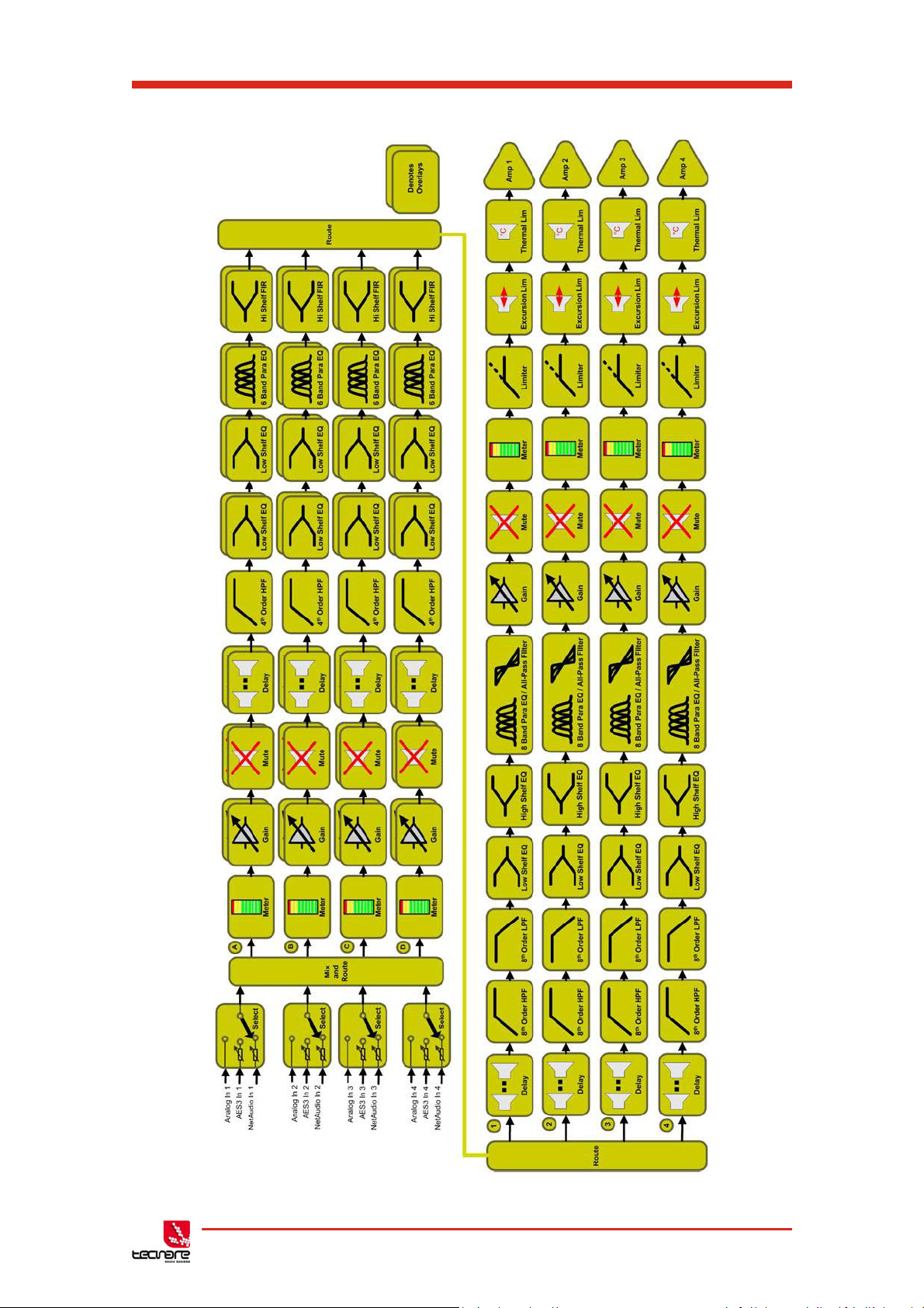
T-44/48 Series Amplifier
Operation Manual
7.1 Processing Block Diagram
T-44/48 Series | rev.
firm. 1.258 and above
50
Page 52

T-44/48 Series Operation Manual
100 1.10
3
1.10
4
36
30
24
18
12
6
0
6
6dB/Oct
12dB/Oct
18dB/Oct
24dB/Oct
48dB/Oct
Butterworth
Frequency, Hz
Magnitude, dB
100 1.10
3
1.10
4
36
30
24
18
12
6
0
6
12dB/Oct
24dB/Oct
48dB/Oct
Linkwitz-Riley
Frequency, Hz
Magnitude, dB
8 EQ and Filter Response Graphs
51 T-44/48 Series | rev.
firm. 1.258 and above
Page 53

T-44/48 Series Amplifier
100 1.10
3
1.10
4
36
30
24
18
12
6
0
6
12dB/Oct
18dB/Oct
24dB/Oct
Bessel
Frequency, Hz
Magnitude, dB
100 1.10
3
1.10
4
36
30
24
18
12
6
0
6
4th Order
8th Order
Hardman
Frequency, Hz
Magnitude, dB
Operation Manual
T-44/48 Series | rev.
firm. 1.258 and above
52
Page 54

T-44/48 Series Operation Manual
100 1.10
3
1.10
4
36
30
24
18
12
6
0
6
24dB/Oct
LIR (Linear Phase)
Frequency, Hz
Magnitude, dB
100 1.10
3
1.10
4
360
300
240
180
120
60
0
Bandwidths 0.1 to 5 Octaves
All-Pass Filter
Frequency, Hz
Phase, degrees
53 T-44/48 Series | rev.
firm. 1.258 and above
Page 55

T-44/48 Series Amplifier
100 1.10
3
1.10
4
15
10
5
0
5
10
15
Low shelf, varying Gain
High shelf, varying Slope
Shelving EQ
Frequency, Hz
Magnitude, dB
100 1.10
3
1.10
4
15
10
5
0
5
10
15
Varying Gain
Varying Bandwidth
Parametric EQ
Frequency, Hz
Magnitude, dB
Operation Manual
T-44/48 Series | rev.
firm. 1.258 and above
54
Page 56

T-44/48 Series Operation Manual
55 T-44/48 Series | rev.
firm. 1.258 and above
Page 57

T-44/48 Series Amplifier
Reinventing The Rules
©2017
Tecnare Sound Systems. All rights reserved.
T-44/48 Series Operation manual
The contents of this manual ar e furnished for informational purposes only, are subject to change without notice, and
should not be construed as a commitment by Exel Acoustics SL. Exel Acoustics assumes no responsibility or liability for
any errors or inaccuracies that may appear in this manual. Except as permitted by applicable copyright law, no part of
this publication may be reproduc ed, stored in a retrieval system, or transmitted, in any form or by any means, electronic,
mechanical, recording or otherwise, without prior written permission from Exel Ac oustics. Tecnare and PCC-Net are
trademarks of Exel Ac oustics SL. System Engineer, BvNet and all third-party tr ademarks mentioned herein are the
property of their respective trademark holders.
Printed in Spain.
Operation Manual
T-44/48 Series | rev.
firm. 1.258 and above
56
Page 58

EXEL ACOUSTICS SL
CL Encinar, 282 - Pol. Ind. Monte Boyal
45950 Casarrubios del Monte (To)
Spain
(e): support@tecnare.com
www.tecnare.com - www.facebok.com/tecnare
(T): +34 918 170 110 - +34 918 171 001
(F): +34 918 183 053
System Engineer™
rev. 2.0 2017
 Loading...