

Page 1

Page 2

This document contains information considered proprietary and confidential to Tecnar Automation Ltd
40101-00024-00– Rev E
Revision date: 2019-03-17
Page 2 of 43
User manual Accuraspray4.0
NOTICES
© 2018 Tecnar Automation Ltd.
No part of this manual may be reproduced in any form or by any means (including electronic storage and retrieval
or translation into a foreign language) without prior agreement and written consent from Tecnar Automation Ltd.
MANUAL PART
40101-00024-00
The material contained in this document is provided “as is” and is subject to change without notice in future
editions.
OVERVIEW:
• Table of content at the beginning of the document
• Table of figures at the beginning of the document
This manual contains the following sections:
• Safety
• Product description
• Installation
• Maintenance
• Operation
• Software
Page 3

This document contains information considered proprietary and confidential to Tecnar Automation Ltd
40101-00024-00– Rev E
Revision date: 2019-03-17
Page 3 of 43
User manual Accuraspray4.0
TABLE OF CONTENT
1 SYSTEM DESCRIPTION ............................................................................................................................................5
1.1 INTRODUCTION ................................................................................................................................................................................... 5
1.2 GENERAL PRECAUTIONS .................................................................................................................................................................... 6
2 DESCRIPTION ...........................................................................................................................................................7
2.1 CONTROLLER ..................................................................................................................................................................................... 8
2.2 SENSOR HEAD .................................................................................................................................................................................. 10
2.3 CABLES, HOSES AND ANTENNAS ....................................................................................................................................................... 11
3 OPERATION SOFTWARE........................................................................................................................................ 12
3.1 USER INTERFACE ............................................................................................................................................................................. 12
3.2 NAVIGATION ICONS........................................................................................................................................................................... 12
3.3 LOGGING IN AS AN ADMINISTR ATOR U SER ........................................................................................................................................ 22
3.4 MANAGING SETUPS .......................................................................................................................................................................... 23
3.5 LOADING A SETUP ............................................................................................................................................................................ 24
3.6 TECHNICAL SPECIFICATION S............................................................................................................................................................. 28
4 INSTALLATION ........................................................................................................................................................ 29
4.1 INSTALLING THE SENSOR HEAD ......................................................................................................................................................... 29
4.2 ACCESSING THE USER INTERFACE .................................................................................................................................................... 34
4.3 SETTING UP THE ACCURASPR AY ON A NETW ORK (OPTIONAL)............................................................................................................ 35
4.4 CONNECTING THE I/OS (OPTIONAL) .................................................................................................................................................. 35
5 MAINTENANCE ....................................................................................................................................................... 37
5.1 MAINTENANCE SCHEDULE ................................................................................................................................................................ 37
5.2 MAINTENANCE PROCEDURES ........................................................................................................................................................... 38
5.3 RECOMMENDED SPARE PARTS ......................................................................................................................................................... 39
6 TROUBLESHOOTING .............................................................................................................................................. 40
6.1 SECTION TROUBLESHOOTING (LED ERROR CODES) ......................................................................................................................... 40
6.2 ERROR REPORTING IN THE USER INTERFACE .................................................................................................................................... 41
!
Page 4

This document contains information considered proprietary and confidential to Tecnar Automation Ltd
40101-00024-00– Rev E
Revision date: 2019-03-17
Page 4 of 43
User manual Accuraspray4.0
TABLE OF FIGURES
FIGURE 1 SCHEMATICAL DESCRIPTION OF THE SYSTEM .............................................................................................7
FIGURE 2 CONTROLLER (FRONT) ...................................................................................................................................8
FIGURE 3 CONTROLLER (BACK) ......................................................................................................................................8
FIGURE 4 SENSOR HEAD (FRONT) ................................................................................................................................ 10
FIGURE 5 SENSOR HEAD (BACK) .................................................................................................................................. 10
FIGURE 6 ACCURASPRAY 4.0 USER INTERFACE ......................................................................................................... 12
FIGURE 7 CAMERA SCREEN .......................................................................................................................................... 14
FIGURE 8 STRIPCHART SCREEN ................................................................................................................................... 17
FIGURE 9 LOGIN WINDOW ............................................................................................................................................. 20
FIGURE 10 PASSWORD SCREEN ................................................................................................................................... 21
FIGURE 11 DIALS PROCESS CONTROL ZONES ............................................................................................................ 22
FIGURE 13 SETUP SELECTION WINDOW ...................................................................................................................... 24
FIGURE 14 SETUP OVERRIDE WI NDOW ........................................................................................................................ 25
FIGURE 15 POSI TION O F THE SENSOR HEAD .............................................................................................................. 30
FIGURE 16 SENSOR HEAD MONTING PLATE DIMENSIONS.......................................................................................... 30
FIGURE 17 M OUNTING THE SENSOR HEAD ................................................................................................................. 31
FIGURE 18 SENSOR HEAD INTERFACE ......................................................................................................................... 31
FIGURE 19 CONTROLLER INTERFACE .......................................................................................................................... 32
FIGURE 20 CONTROLLER STATUS LED ........................................................................................................................ 32
FIGURE 21 SENSOR HEAD ALIGNEMENT BUTTON ....................................................................................................... 33
FIGURE 22 SENSOR HEAD WORKING DISTANCE ......................................................................................................... 33
FIGURE 23 CONTROLLER ETHERNET PORT ................................................................................................................. 34
FIGURE 24 ACCURASPRAY 4.0 USER INTERFACE ....................................................................................................... 34
FIGURE 25 I/O PORT ....................................................................................................................................................... 35
Page 5

This document contains information considered proprietary and confidential to Tecnar Automation Ltd
40101-00024-00– Rev E
Revision date: 2019-03-17
Page 5 of 43
User manual Accuraspray4.0
!
1 SYSTEM DESCRIPTION
1.1 INTRODUCTION
The present document gives a complete description and principle of
operation of the Accuraspray 4.0 sensor as well as a description of its
components.
1.1.1 OVERVIEW
The main purpose of the Accuraspray 4.0 is to ensure consistent, highquality coatings by monitoring the in-flight particles and plume properties
before each spray run. This ensures that the spray properties are within
predetermined acceptance ranges for ideal coating and performance.
To help detect potential issues such as electrode wear, partial clogging of
the nozzle or in the powder injection system, and instability of the powder
feeder before the coating process, the Accuraspray monitors:
• Particle’s temperature and velocity;
• Plume profile and intensity;
• Part temperature (optional);
The Accuraspray 4.0 can also be used to:
• Develop and optimize spray parameters;
• Transfer parameters from one booth to another (anywhere in the world);
• Transfer parameters from one spray gun to another;
• Extend the useful lifespan of hardware;
• Significantly reduce the number of test coupons;
• Troubleshoot day-to-day issues;
!
Page 6
This document contains information considered proprietary and confidential to Tecnar Automation Ltd
40101-00024-00– Rev E
Revision date: 2019-03-17
Page 6 of 43
User manual Accuraspray4.0
!
1.2 GENERAL PRECAUTIONS
The following precautions should be observed at all times while operating
the Accuraspray 4.0. Tecnar Automation Ltd. assumes no liability
whatsoever for a user’s failure to comply with these precautions or the
warnings throughout this manual.
To protect your Accuraspray 4.0 from damage, you must:
• Connect it to an unloaded, properly grounded power line (50–60 Hz. 100240VAC, 50-60Hz, 1.5 A).
• We also recommend using an additional power line filter to filter out any
power surges or bursts;
• Use it at an ambient temperature between 4 and 45 °C;
• Supply 30 LPM (2CFM) of cooling/cleaning air at 1.7–2.7 bar (25–40 psi)
to the sensor head AT ALL TIMES while the unit is powered on.;
• Use only original spare parts.
All Accuraspray 4.0 users should read this user manual, take the web-based
introduction and training session, and contact Tecnar with any further
questions. We also recommend that a copy of the user manual be kept near
the equipment at all times.
!
Page 7
This document contains information considered proprietary and confidential to Tecnar Automation Ltd
40101-00024-00– Rev E
Revision date: 2019-03-17
Page 7 of 43
User manual Accuraspray4.0
!
2 DESCRIPTION
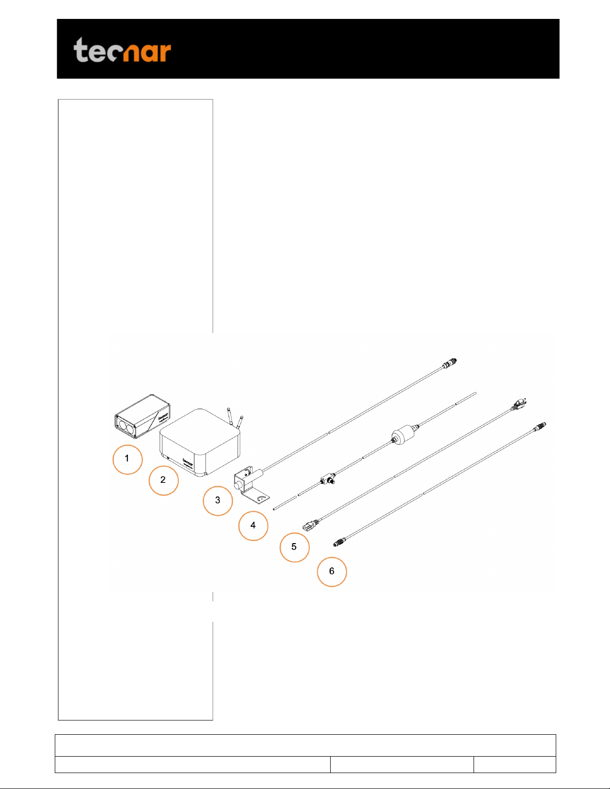
FIGURE 1 SCHEMATICAL DESCRIPTION OF THE SYSTEM
The Accuraspray 4.0 system includes the following elements:
1) A sensor head;
2) A controller;
3) A substrate pyrometer (optional);
4) Air hoses and filter;
5) Controller power cable;
6) Sensor head power and communication cable;
Each elements are described in details on the following pages.
!
Page 8

This document contains information considered proprietary and confidential to Tecnar Automation Ltd
40101-00024-00– Rev E
Revision date: 2019-03-17
Page 8 of 43
User manual Accuraspray4.0
!
2.1 CONTROLLER
The controller must be kept in a ventilated area to reduce the risk of
overheating.
The controller receives readings from the sensor head. It processes the data
and broadcasts the results to the user interface(s).
FIGURE 2 CONTROLLER (FRONT)
FIGURE 3 CONTROLLER (BACK)
Page 9

This document contains information considered proprietary and confidential to Tecnar Automation Ltd
40101-00024-00– Rev E
Revision date: 2019-03-17
Page 9 of 43
User manual Accuraspray4.0
!
Component
Description
1. LED
LED
Off: Power supply is OFF;
Green: The system is working properly;
Yellow: Sensor head is not connected;
Red: Unit power up but an error is detected.
2. Wi-Fi antenna
Used to access the Accuraspray user interface
through a wireless network connection. The
Wi-Fi connection acts as a Hotspot. It can be
disabled but not reconfigured.
3. Sensor head port
Used to power and communicate with the
sensor head.
4. Power switch
Used to active the unit.
5. User interface
port
Used to interface the Accuraspray to the user’s
spray controller via digital I/Os.
6. Ethernet
Used to access the Accuraspray user interface
through a wired network connection.
7. Power inlet
Provides power to the Accuraspray.
Connect it to an unloaded, properly grounded
power line (100-240VAC, 50-60Hz, 1.5 A).
Page 10
This document contains information considered proprietary and confidential to Tecnar Automation Ltd
40101-00024-00– Rev E
Revision date: 2019-03-17
Page 10 of 43
User manual Accuraspray4.0
!
2.2 SENSOR HEAD
The sensor head measures the following particles and spray plume
properties:
• Particles velocity;
• Particles temperature;
• Spray plume geometry (width, position) and intensity.
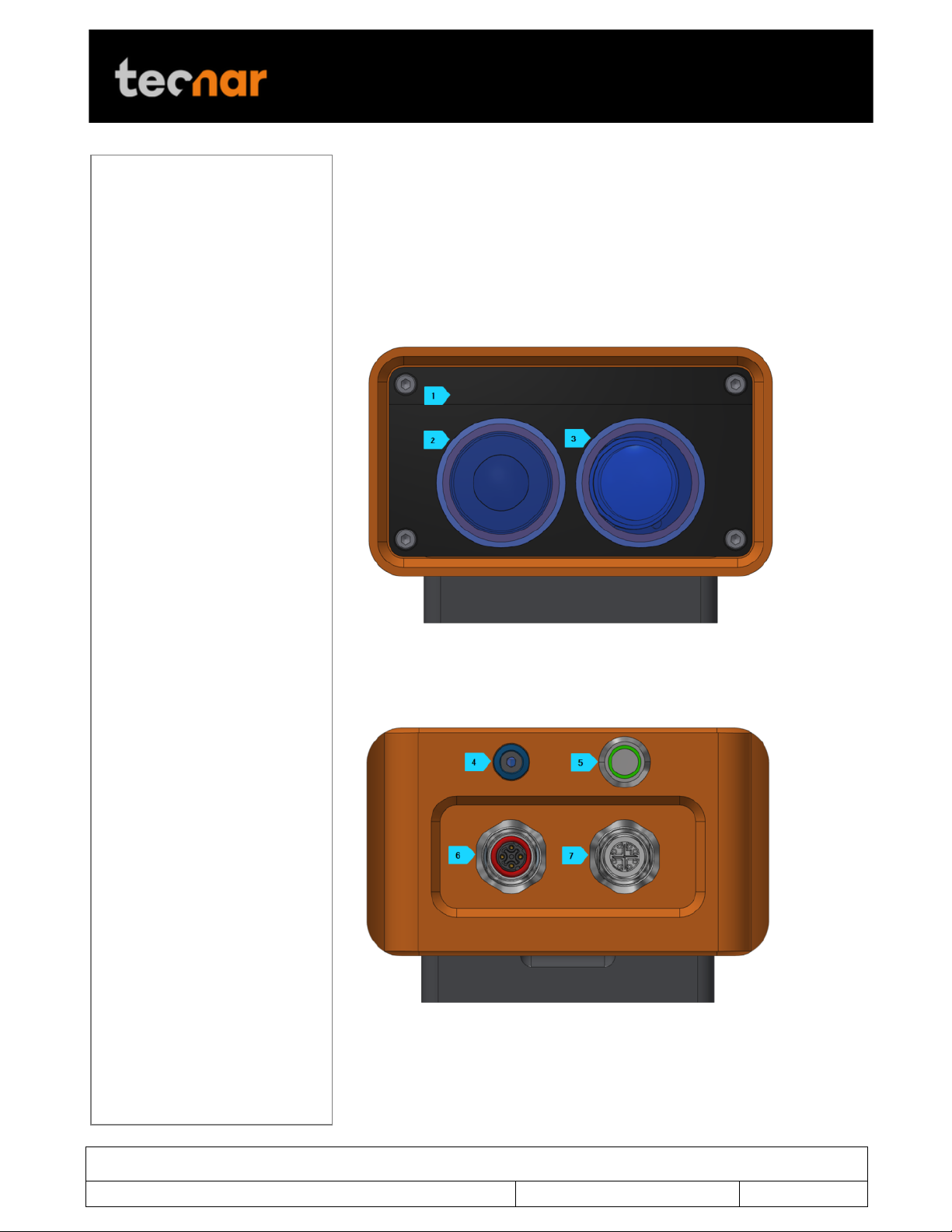
FIGURE 4 SENSOR HEAD (FRONT)
!
FIGURE 5 SENSOR HEAD (BACK)
Page 11

This document contains information considered proprietary and confidential to Tecnar Automation Ltd
40101-00024-00– Rev E
Revision date: 2019-03-17
Page 11 of 43
User manual Accuraspray4.0
!
Component
Description
1. Air knife
The air knife is used to keep the Accuraspray
windows clean and free of dust.
2. Optical system
viewport
Viewport of the temperature and velocity
measurement sensor.
3. Camera viewport
Viewport of the camera used to characterize
the plume geometry.
4. Air supply port
Compressed air is used both as active cooling
for the head’s internal components and, as it is
exhausted from the head, to generate an air
knife that keeps the viewport windows clean.
5. Alignment beam
switch
Activation switch for the alignment beam.
6. Substrate
pyrometer port
Used to power and communicate with the
optional substrate pyrometer sensor.
7. Communication
port
Used to power the sensor head and
communicate with the controller.
Cables/Hoses/Antennas
Description
IEC power cable
Used to connect the Accuraspray to a
power outlet.
Communication cable
Communication between the controller
and the measurement head.
Antennas
Used for WiFi communication.
Compressed air hoses
Provide compressed air to the
measurement head for cooling and
purging purposes.
• One hose connects the
compressed air supply to the air
filter;
• One hose connects the air filter to
the pressure regulator;
• One hose connects the regulator
to the measurement head;
2.3 CABLES, HOSES AND ANTENNAS
The Accuraspray 4.0 is delivered with several cables, hoses and antennas,
which are described in the following table.
Page 12
This document contains information considered proprietary and confidential to Tecnar Automation Ltd
40101-00024-00– Rev E
Revision date: 2019-03-17
Page 12 of 43
User manual Accuraspray4.0
!
Icons
Description
Access the main measurement screen.
FIGURE 6 ACCURASPRAY 4.0 USER INTERFACE
3 OPERATION SOFTWARE
3.1 USER INTERFACE
The user interface can be accessed with most internet browsers. It connects
to the controller via an Ethernet cable or Wi-Fi network.
3.2 NAVIGATION ICONS
Different icons are displayed at the top of the Accuraspray user interface in
order to navigate between the different screens. The following table
describes those icons.
Page 13

This document contains information considered proprietary and confidential to Tecnar Automation Ltd
40101-00024-00– Rev E
Revision date: 2019-03-17
Page 13 of 43
User manual Accuraspray4.0
!
Access the charts screen.
Access the setup screen (Only when logged in as
Operator or Administrator)
Access the menu to change user’s passwords.
Take control and access the configuration screen
(Operators and Administrators only)
Log in.
Log out.
! !
Page 14
This document contains information considered proprietary and confidential to Tecnar Automation Ltd
40101-00024-00– Rev E
Revision date: 2019-03-17
Page 14 of 43
User manual Accuraspray4.0
!
3.2.1 CAMERA SCREEN
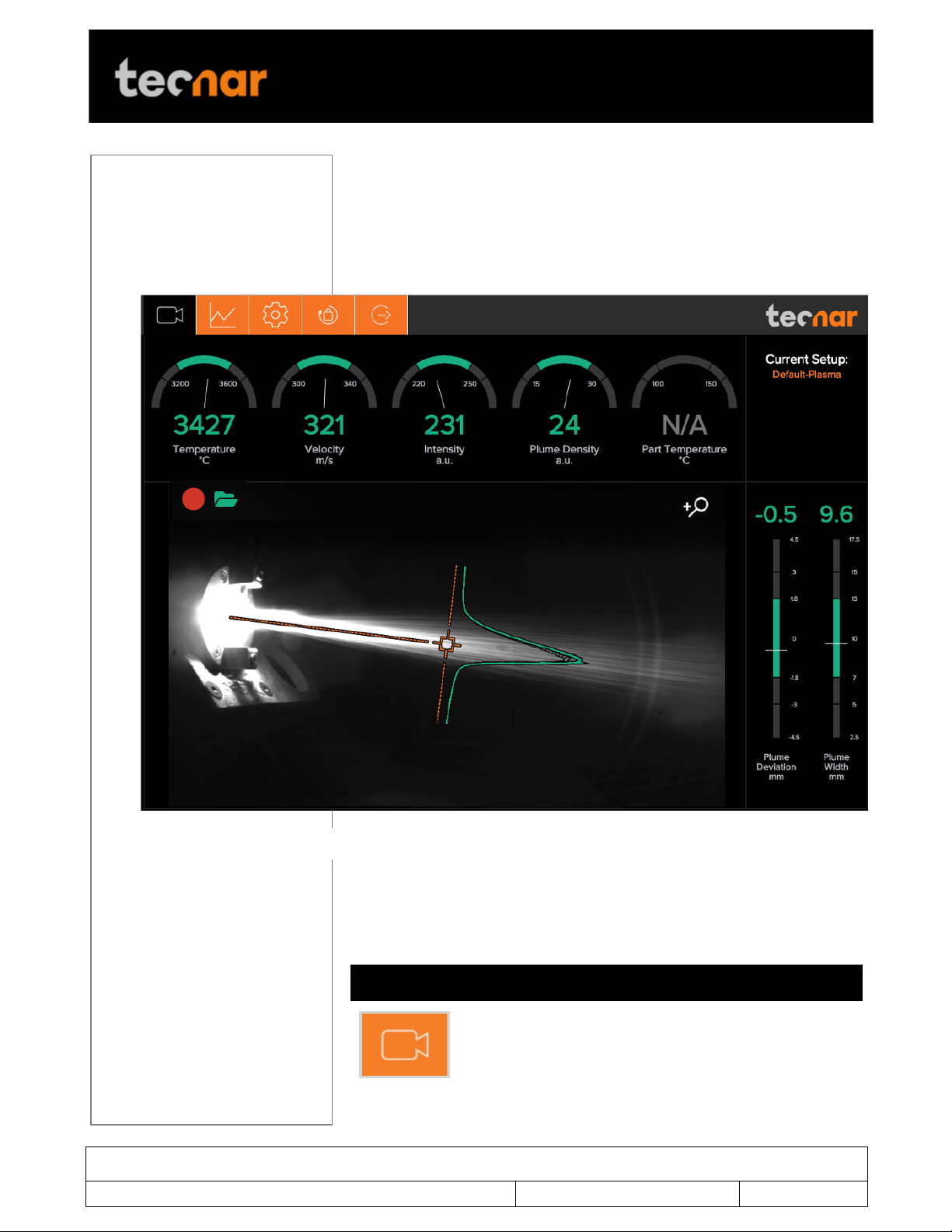
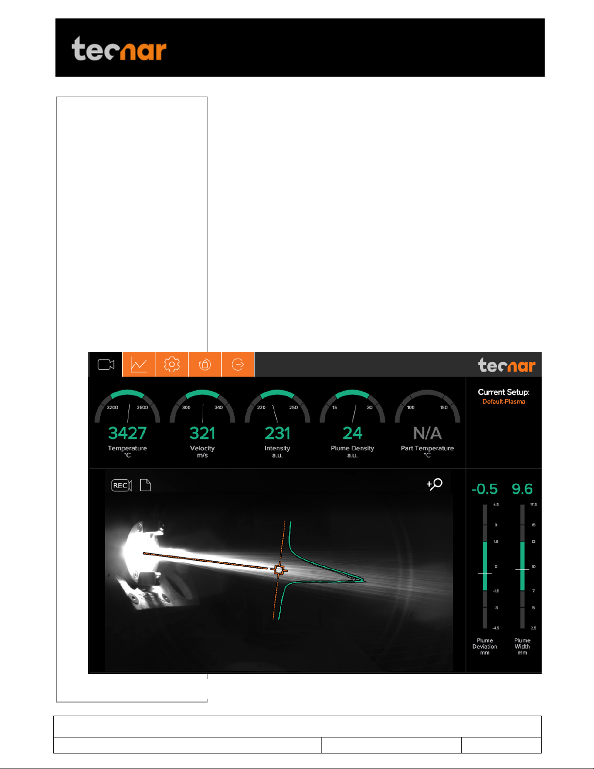
FIGURE 7 CAMERA SCREEN
The camera screen displays, in real time, all measurements taken by the
Accuraspray.
The measurements, are displayed at the top and to the right of the screen.
Color codes indicate whether or not the measurements are within the
acceptance range as defined in the setup by the process engineer. A
measurement fully within the acceptance range is shown in green, a
measurement just barely within the acceptance range is shown in yellow,
and a measurement outside the acceptance range is shown in red.
Corrective actions should be taken to ensure that all measurements are
within the acceptance range and displayed in green.
In the middle of the screen, in the camera view, an orange bullseye
represents the position where the particle’s temperature and velocity are
being measured. The distance between the bullseye and the tip of the spray
gun, called the standoff distance, is represented by the dotted horizontal
orange line. The green curve shows the plume intensity profile as measured
by the sensor along the vertical line.
Page 15

This document contains information considered proprietary and confidential to Tecnar Automation Ltd
40101-00024-00– Rev E
Revision date: 2019-03-17
Page 15 of 43
User manual Accuraspray4.0
!
Parameters
Description
Temperature
Average particles temperature that are passing
through the sensor’s measurement volume
(bullseye).
Velocity
Average particles speed that are passing through the
sensor’s measurement volume (bullseye).
Intensity
Intensity of the spray plume.
This measurement is very sensitive to minute
changes in the spray conditions. The parameters that
have the strongest effect on the plume intensity are:
• Particles temperature;
• Average particles diameter;
• Feedstock emissivity;
• Feed rate.
Plume density
Provides an indication of the particles flow rate.
Part temperature
Temperature of the substrate on which the coating is
applied.
Plume deviation
Deviation of the plume position against the bullseye.
Plume width
Width of the spray plume.
The different measurements provided by the Accuraspray are described in
details in the table below.
3.2.1.1 Zoom in / out
It is possible to zoom in on the center of the image where the bullseye is
located.
To do so, click on the magnifying glass icon. This will enlarge the image so
that the sampling line, the dotted vertical line overlaid on the camera image,
takes 50% of the screen. To return to the full screen click on the magnifying
glass again.
This feature is especially useful for HVAF/HVOF where the plume is quite
narrow and can be difficult to see when viewing the full camera frame.
3.2.1.2 Recording a video sequence
Sequences can be recorded and recalled using the icons on the top left
corner of the video. The camera icon is used to launch a recording.
Once the Accuraspray is recording, the letters in the camera will turn red to
indicate that the Accuraspray is recording.
To stop recording, click on the square icon next to the camera. This will
automatically download the sequence to your computer in your web browser
default download directory.
Page 16

This document contains information considered proprietary and confidential to Tecnar Automation Ltd
40101-00024-00– Rev E
Revision date: 2019-03-17
Page 16 of 43
User manual Accuraspray4.0
!
Recorded video sequences are not stored on the Accuraspray Controller.
3.2.1.3 Playing back a video sequence
To open a saved sequence, click on the folder icon, select the sequence
that you want to replay.
As mentioned previously, the video sequences are not stored on the
Accursaspray controller. You will find them on your computer in your default
download directory or wherever you have stored them.
When replaying a sequence an X icon will appear. It is used to exit replay
mode and return back to live mode.
It is possible to pause a sequence using the Pause icon and resume
playback using the Play icon.
!! !
Page 17
This document contains information considered proprietary and confidential to Tecnar Automation Ltd
40101-00024-00– Rev E
Revision date: 2019-03-17
Page 17 of 43
User manual Accuraspray4.0
!
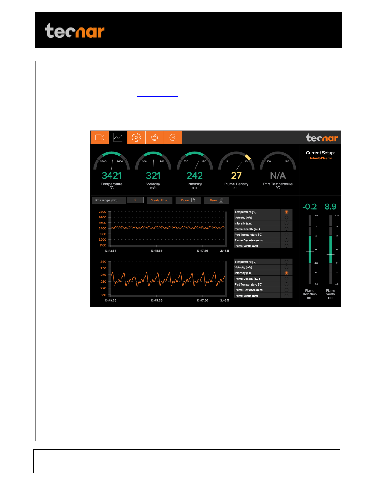
FIGURE 8 STRIPCHART SCREEN
3.2.2 STRIPCHART SCREEN
The stripchart screen displays the evolution over time of measurements
available on the camera screen. For the measurement descriptions, see the
camera screen section.
In the middle of the screen are two graphs, each displaying one
measurement. It’s possible to select which measurement to display from the
table located to the right of the graphs.
3.2.2.1 Adjusting the time display
The time duration displayed on the strip charts can be adjusted using the
text box at the top of the page. The charts can display up to 60 minutes of
measurements.
The last 60 minutes are stored in the database and can be recalled at any
time.
3.2.2.2 Adjusting the Y-axis display
The range of the strip charts Y axis can be adjusted in two ways:
• Fixed - Sets the Y-axis limits (min and max values) according to the
Acceptance Ranges as defined by the setup.
Page 18

This document contains information considered proprietary and confidential to Tecnar Automation Ltd
40101-00024-00– Rev E
Revision date: 2019-03-17
Page 18 of 43
User manual Accuraspray4.0
!
• Auto – Sets the Y-axis limits (min and max values) according to the full
scale of the values captured by the sensor.
3.2.2.3 Production Reports
Production reports can be generated from the Strip Chart screen. When
users select “Save” the data contained in the strip charts and a screen
shot of the camera screen will be copied into a .pdf and .csv files.
The production reports are stored on the Accuraspray controller’s hard
drive. The directory where the files are stored is accessible by clicking on
the “Open” icon. It also contains all the strip charts. The duration of the
strip charts in the production report is the same as what was displayed in
the User interface at the time when the production report was generated.
If desired you can take the strip charts .csv file and generate your own
graphs to manipulate the data.
!! !
Page 19

This document contains information considered proprietary and confidential to Tecnar Automation Ltd
40101-00024-00– Rev E
Revision date: 2019-03-17
Page 19 of 43
User manual Accuraspray4.0
!
3.2.3 LOGGING IN
The power of this interface is the ability to have multiple, simultaneous,
users (up to 5) of the software. For instance:
• One user or “the operator” can be actually be using the system for
measurement (will need to “take control” as covered in subsequent slides)
• Another user can be “watching” the “operator” from the engineering office
via the network or wireless
• Another user can be viewing saved files from previous runs in the QC
department
When accessing the Accuraspray interface, users are in viewer mode and
can only visualize the sensor’s readings like the engineer or QC person
discussed earlier.
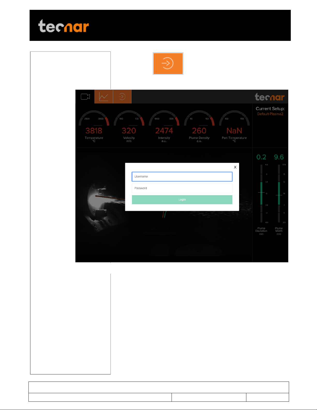
In order to actually use the sensor and record sequences it is necessary to
log in by clicking the designated icon. Users can Log in either as Operators
or Administrator.
• Operators (user name: operator) can change the setup used by the
sensor and record measurement sequences. The default password for
operators is: accura.operator
• Administrators (user name: admin) have the same rights as the
Operators and can created, modify and delete setups. The default password
for administrator is: accura.admin
Page 20
This document contains information considered proprietary and confidential to Tecnar Automation Ltd
40101-00024-00– Rev E
Revision date: 2019-03-17
Page 20 of 43
User manual Accuraspray4.0
!
FIGURE 9 LOG IN WINDOW
To log in click to display the login window and enter your
credentials
! !
Page 21
This document contains information considered proprietary and confidential to Tecnar Automation Ltd
40101-00024-00– Rev E
Revision date: 2019-03-17
Page 21 of 43
User manual Accuraspray4.0
!
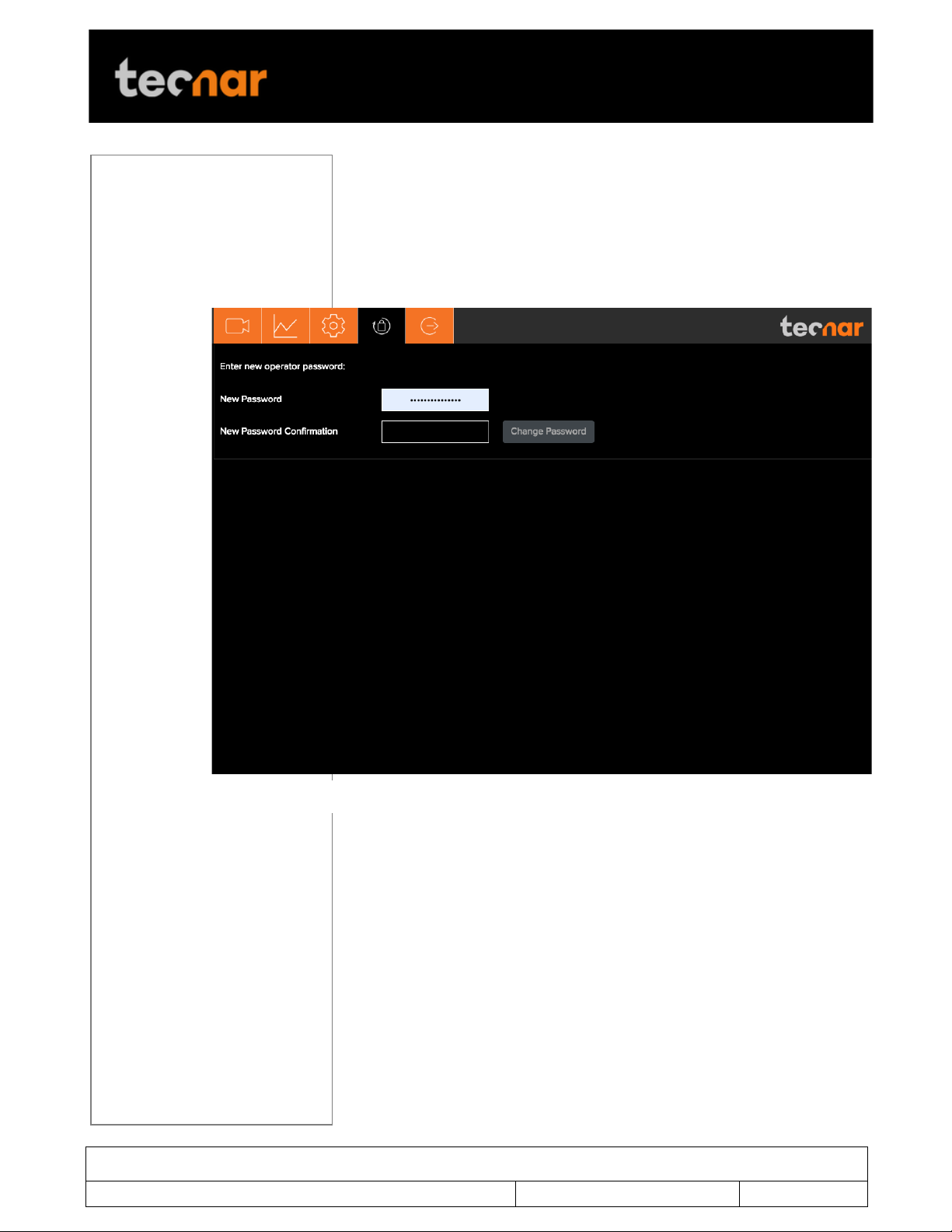
FIGURE 10 PASSWORD SCREEN
3.2.4 MODIFYING USER’S PASSWORD
To modify user’s password, click on the lock icon at the top of the screen.
Once on the Password page enter a new password and click ‘Change
Password’ to apply it.
Note that you will have to login either as Operator or Administrator to access
this screen.
Page 22
This document contains information considered proprietary and confidential to Tecnar Automation Ltd
40101-00024-00– Rev E
Revision date: 2019-03-17
Page 22 of 43
User manual Accuraspray4.0
!
Red zone
Red zone
Yellow zone
Yellow zone
Green zone
20%
20%
60%
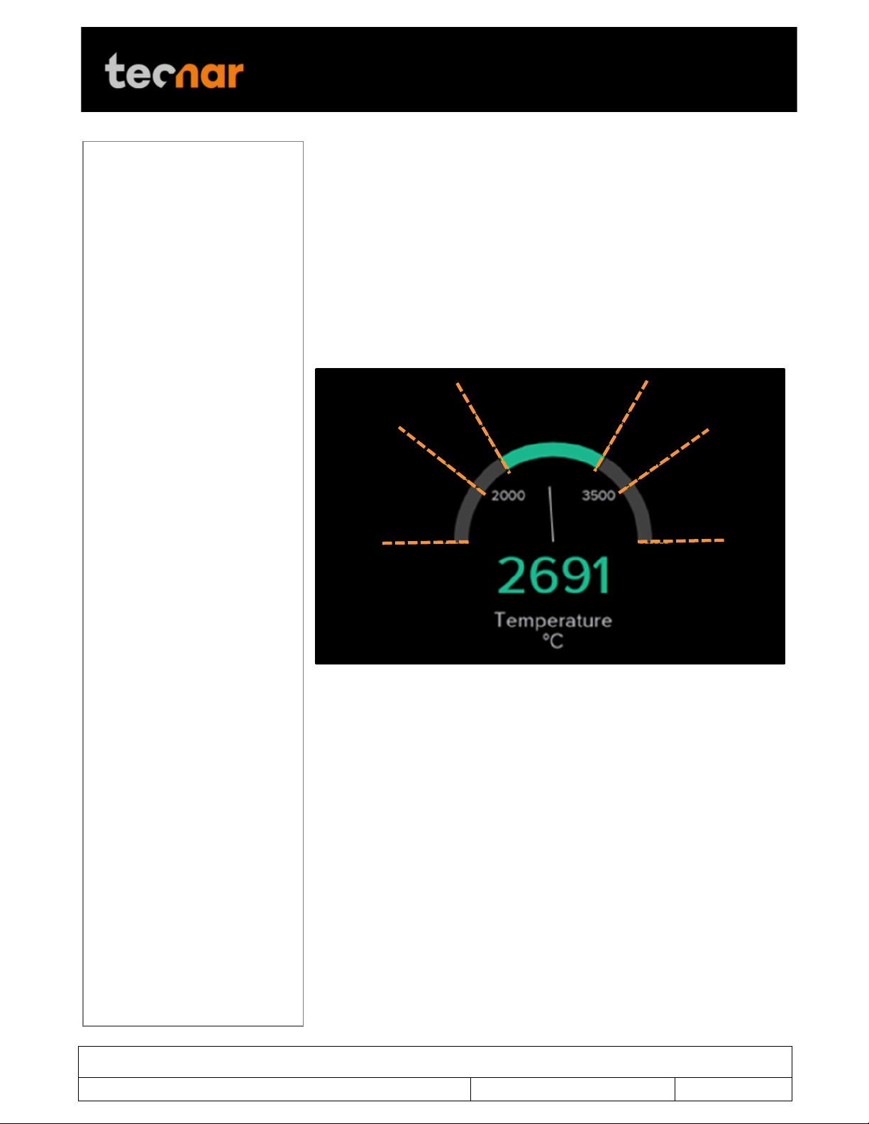
FIGURE 11 DIALS PROCESS CONTROL ZONES
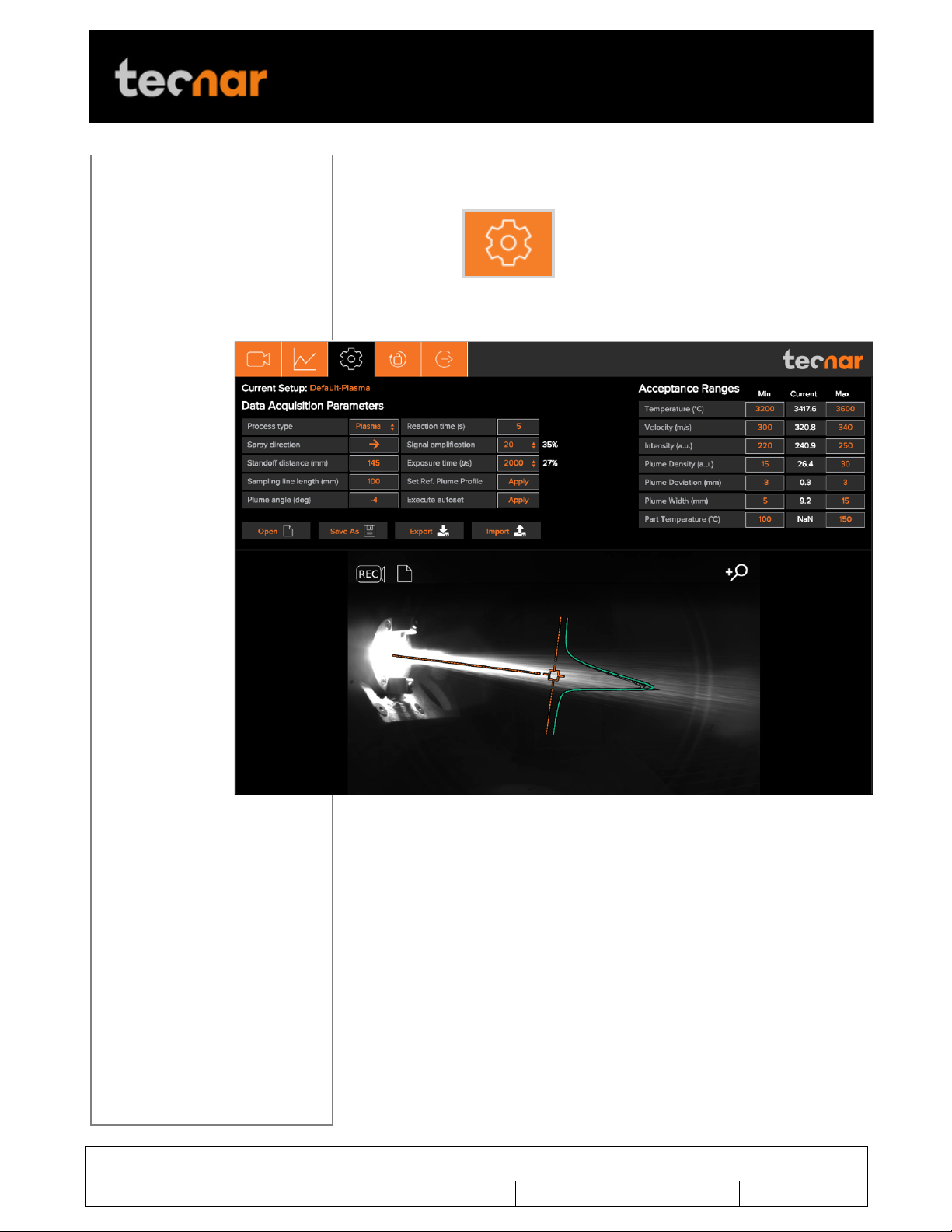
3.2.5 SETUP SCREEN (OPERATOR AND ADMINISTRATOR ONLY)
The left side of the setup screen shows the data acquisition parameters for
the current process.
The right side of the configuration screen shows the acceptance ranges.
The min and max values represent the values past which the process is
considered off (red zone). The range between those values contains the
green and yellow zones. The green value represents 60% of the full range
between the min and max while the yellow regions warns the operators that
the measurement is approaching the red zone. The yellow zones are
located 20% from the min and max values of the process.
3.3 LOGGING IN AS AN ADMINISTRATOR USER
When the user interface is accessed, the home screen is displayed with
Viewer user access. In order to make changes to the sensor configurations
or record sequences it is necessary to log in.
• Enter your username (Operator) and password (accura.tecnar) and click
Login. The home screen is displayed with Administrator user access.
!
Page 23
This document contains information considered proprietary and confidential to Tecnar Automation Ltd
40101-00024-00– Rev E
Revision date: 2019-03-17
Page 23 of 43
User manual Accuraspray4.0
!
3.4 MANAGING SETUPS
The Setup screen is where the different parameters of the sensor head are
!
managed. Click to access the configuration screen.
Page 24
This document contains information considered proprietary and confidential to Tecnar Automation Ltd
40101-00024-00– Rev E
Revision date: 2019-03-17
Page 24 of 43
User manual Accuraspray4.0
!
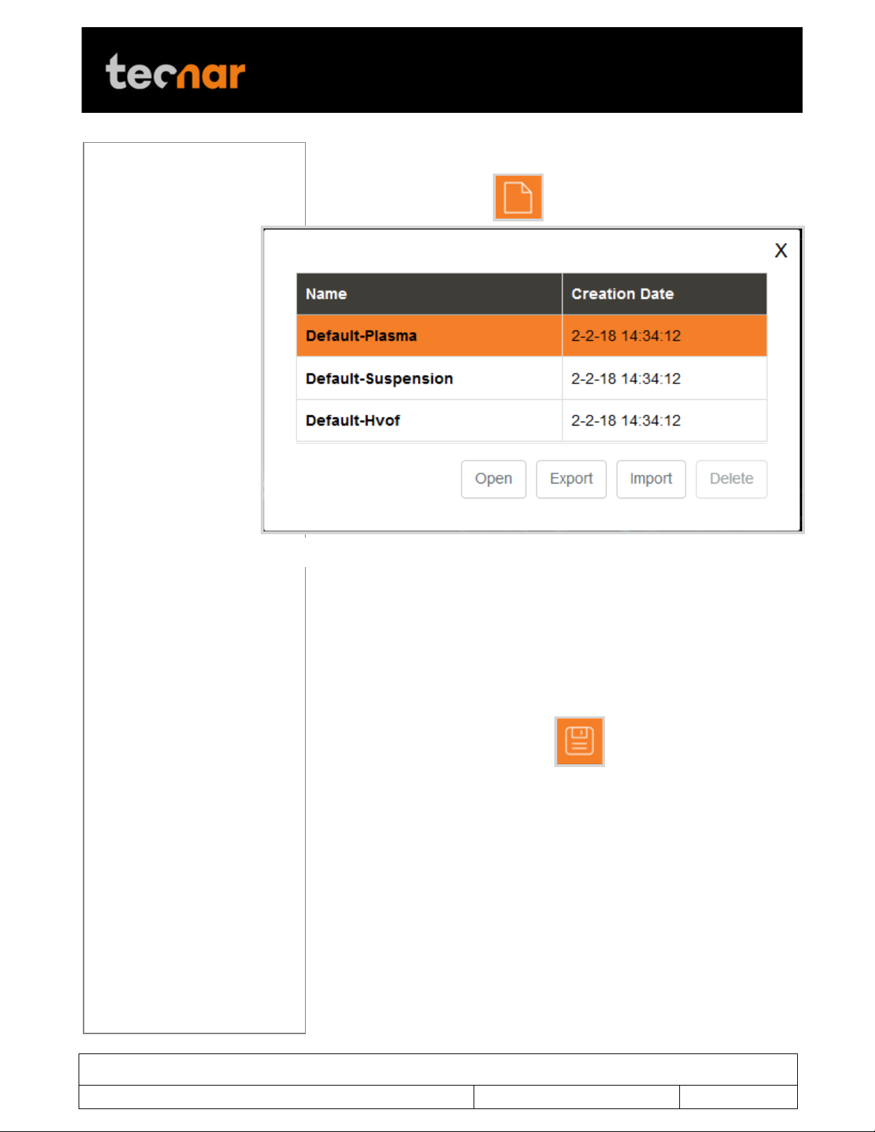
FIGURE 12 SETUP SELECTION WINDOW
3.5 LOADING A SETUP
On the Setup screen, click . This displays the list of setups.
Select the setup and click Open. The new setup is automatically applied.
3.5.1 SAVING A SETUP
Once you have modified any parameter on the configuration screen, you
can save them as a new setup or overwrite the existing setup.
On the configuration screen, click . This displays the following
window.
Page 25
This document contains information considered proprietary and confidential to Tecnar Automation Ltd
40101-00024-00– Rev E
Revision date: 2019-03-17
Page 25 of 43
User manual Accuraspray4.0
!
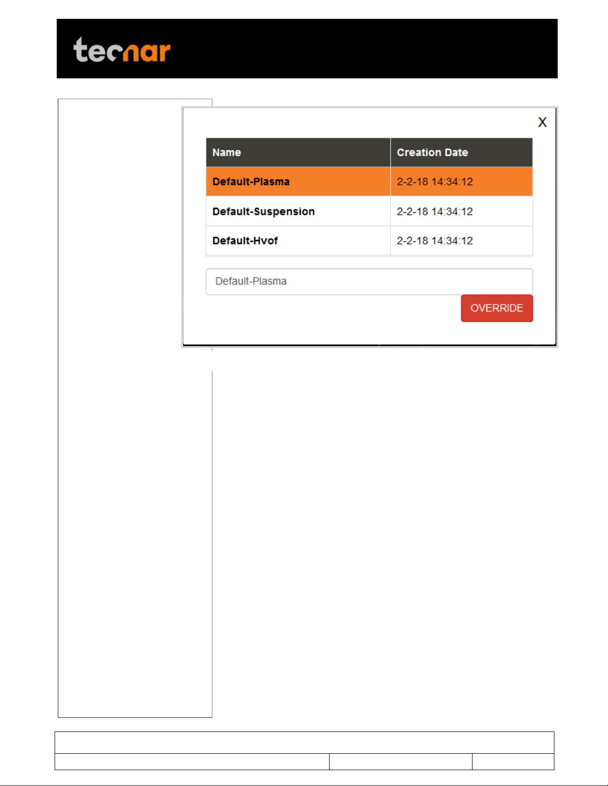
FIGURE 13 SETUP OVERRIDE WINDOW
To overwrite a setup, select a setup and click Override. The new
parameters are automatically saved.
To add a new setup enter a new setup name and Save.
3.5.2 SETUPS IMPORT AND EXPORT
Setups can be exported from one Accuraspray units and imported to
another. When clicking on the “Export” button a setup file will be
downloaded on your computer.
To import a setup, simply click on the “Import” button and select the setup
file that you wish to import from your computer.
This enables you to ensure that multiples sensors are using the same
setting. That is especially useful to compare two booths that are identically
set-up using two different Accuraspray units.
Page 26

This document contains information considered proprietary and confidential to Tecnar Automation Ltd
40101-00024-00– Rev E
Revision date: 2019-03-17
Page 26 of 43
User manual Accuraspray4.0
!
Parameters
Description
Spray direction
Particles travel direction (left to right or right to left)
in the Accuraspray field of view.
Standoff
distance
Distance between the Accuraspray measurement
point (bullseye) and the spray gun output. Typically,
it is the process spray distance.
Plume angle
This value tilts the sampling line so that it lays
perpendicular to the general direction of the particle
flow (typically -5° for top injected plasma spraying
and 0° for HVOF spraying).
Sampling line
length
This value determines the length, in the plane of the
plume, of the path along which the intensity profile
is measured. It is normally set to about four times
the regular plume width.
Process type
This value indicates to the sensor if the process
brightness is high or low. Typically, SPS, Arc spray
and SSPS are considered high brightness
processes while HVOF and HVAF are considered
low brightness.
Reaction Time
Length of the rolling average used by the sensor to
display measurements. This parameter is used to
smooth out natural variations in the process that
would make the sensor’s reading unstable and
unusable for process control.
Typical reaction time for APS and Wire arc is 5 to 15
seconds. For HVOF/HVAF 1 to 5 seconds is usually
sufficient.
Signal
amplification
This value needs to be increased until signal level
reaches roughly 50% (the % value next to the
amplification level is the level of saturation).
Normally, the autoset will take care of this adjustment
for you.
Exposure time
This value needs to be increased until signal level
reaches roughly 50% (the % value next to the
amplification level is the level of saturation).
Normally, the autoset will take care of this adjustment
for you.
3.5.3 SETUP PARAMETERS
The table below explain the Data acquisition parameters – Used to
configure the Accuraspray according to the spray process you’ll be
monitoring.
Page 27

This document contains information considered proprietary and confidential to Tecnar Automation Ltd
40101-00024-00– Rev E
Revision date: 2019-03-17
Page 27 of 43
User manual Accuraspray4.0
!
Save Reference
curve
By clicking this button, the user captures the current
plume profile and sets it as the reference for future
measurement.
Execute Autoset
This feature automatically adjusts the “exposure
time” for the camera and the “signal amplification” for
the particle’s velocity and temperature
measurments.
These settings can be modified manually but it is
easier via the AUTO SET.
However, before this can be accomplished, the spray
plume has to be centered on the bullseyes and the
following data acquisition parameters must be
entered:
• Process type;
• Spray direction;
• Standoff distance;
• Sampling line length;
!
Page 28

This document contains information considered proprietary and confidential to Tecnar Automation Ltd
40101-00024-00– Rev E
Revision date: 2019-03-17
Page 28 of 43
User manual Accuraspray4.0
!
Parameters
Description
Width
110 mm (4.33 in.)
Height
62 mm (2.44 in.)
Length
790 mm (31.10 in.)
Weight
1.85 kg (4.1 lb.)
Working distance from
spray gun axis
200 mm (7.87 in.)
Particle temperature
measurement range
1,000 °C (1,832 °F) and higher at 3%
accuracy
Particle velocity
measurement range
5–1,200 m/s at 3% accuracy
Plume relative intensity
measurement
2% precision
Plume geometry
measurement
0.1 mm (0.004 in.) accuracy
Camera field of view
400 mm (15.75 in.)
Particle’s measurement
volume
3.2 mm x 10 mm x 25 mm (0.13 in. x 0.39
in. x 0.98 in.)
Parameters
Description
Width (a)
230 mm (9.06 in.)
Height (b)
100 mm (3.94 in.)
Length (c)
230 mm (9.06 in.)
Weight
4.40 kg (9.7 lb.)
Power requirement
100–240 VAC, 50–60 Hz, 1.5 A, autoswitch
3.6 TECHNICAL SPECIFICATIONS
3.6.1 SENSOR HEAD
3.6.2 CONTROLLER
Page 29
This document contains information considered proprietary and confidential to Tecnar Automation Ltd
40101-00024-00– Rev E
Revision date: 2019-03-17
Page 29 of 43
User manual Accuraspray4.0
!
4 INSTALLATION
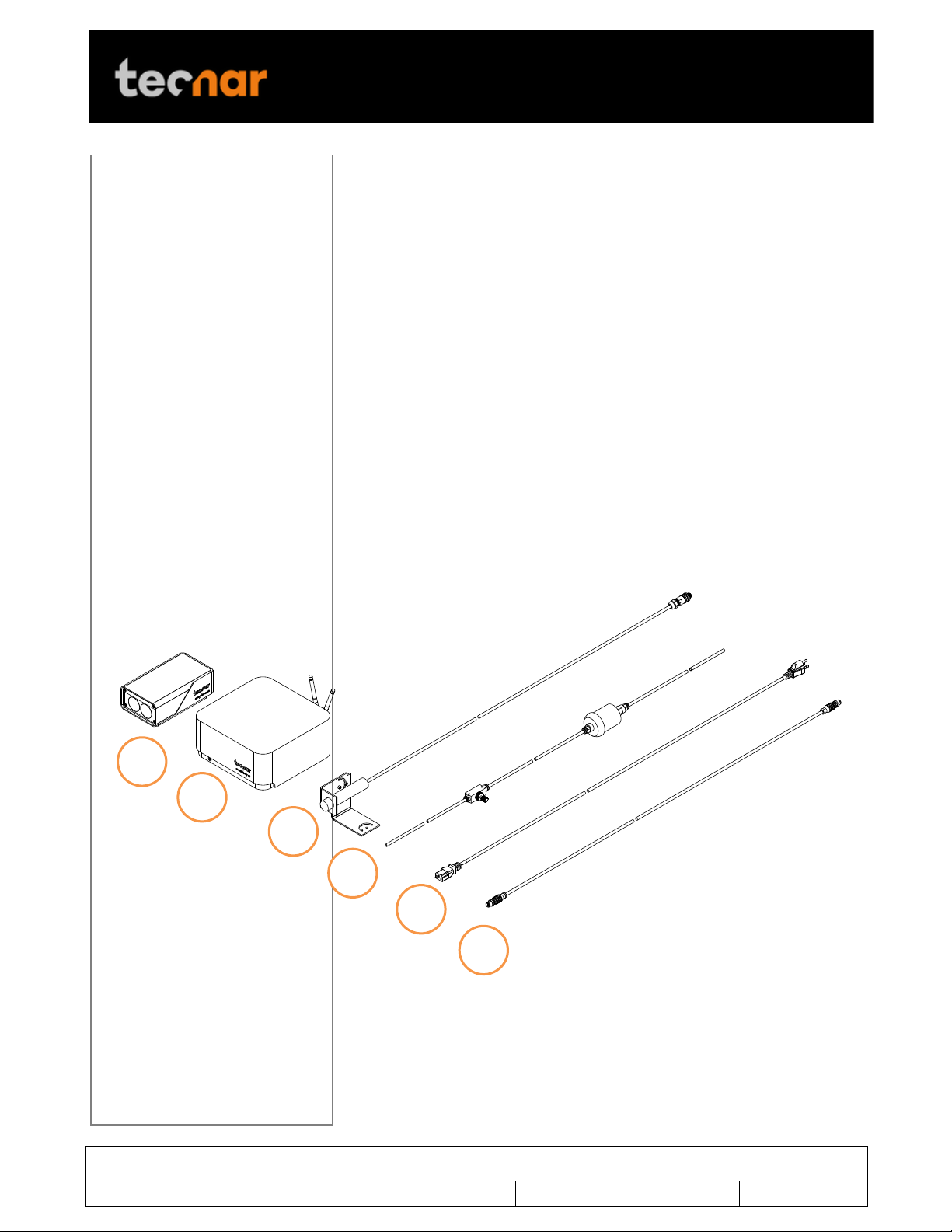
1 2 3
4
5
6
4.1 INSTALLING THE SENSOR HEAD
4.1.1 UNPACKING THE PARTS
Carefully open the box, remove the content, and set it on a work surface.
The box should contain the following items:
1. Sensor head;
2. Controller;
3. Substrate pyrometer and its support bracket (optional);
4. Air filter and hoses;
5. Controller power cable;
6. Communication cable between the head and controller;
!
!
Page 30
This document contains information considered proprietary and confidential to Tecnar Automation Ltd
40101-00024-00– Rev E
Revision date: 2019-03-17
Page 30 of 43
User manual Accuraspray4.0
!
4.1.2 INSTALLING THE SENSOR HEAD
4.1.2.1 Where to install
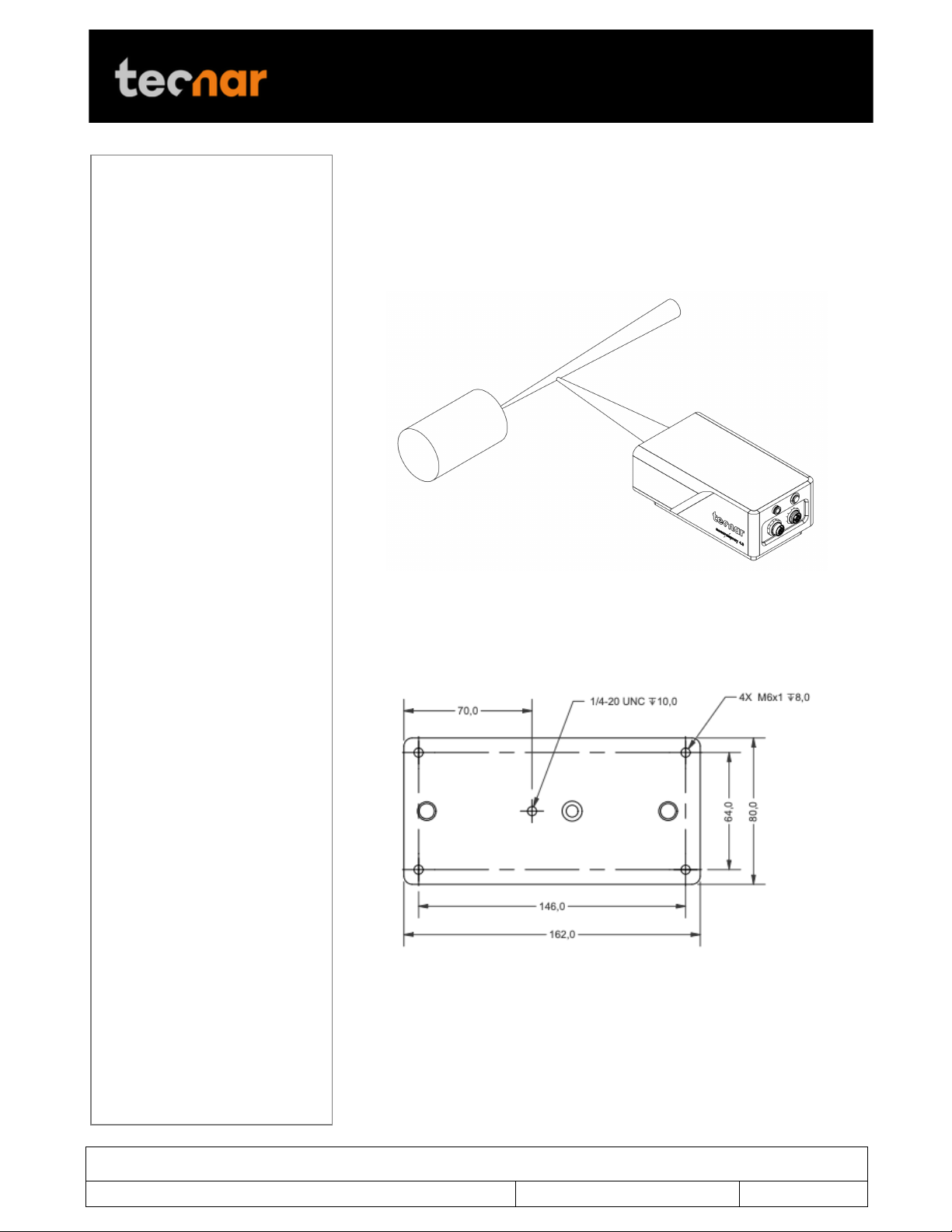
Install the sensor head in the spray booth at a location easily reachable by
the robot (spray gun). Also, ensure that the sensor head does not interfere
with normal spraying operations.
FIGURE 14 POSITION OF THE SENSOR HEAD
Install the sensor head on a sturdy mounting that does not vibrate or move
during spraying. Refer to the following schematic of the Accuraspray
mounting plate.
!
FIGURE 15 SENSOR HEAD MONTING PLATE DIMENSIONS
!
Page 31
This document contains information considered proprietary and confidential to Tecnar Automation Ltd
40101-00024-00– Rev E
Revision date: 2019-03-17
Page 31 of 43
User manual Accuraspray4.0
!
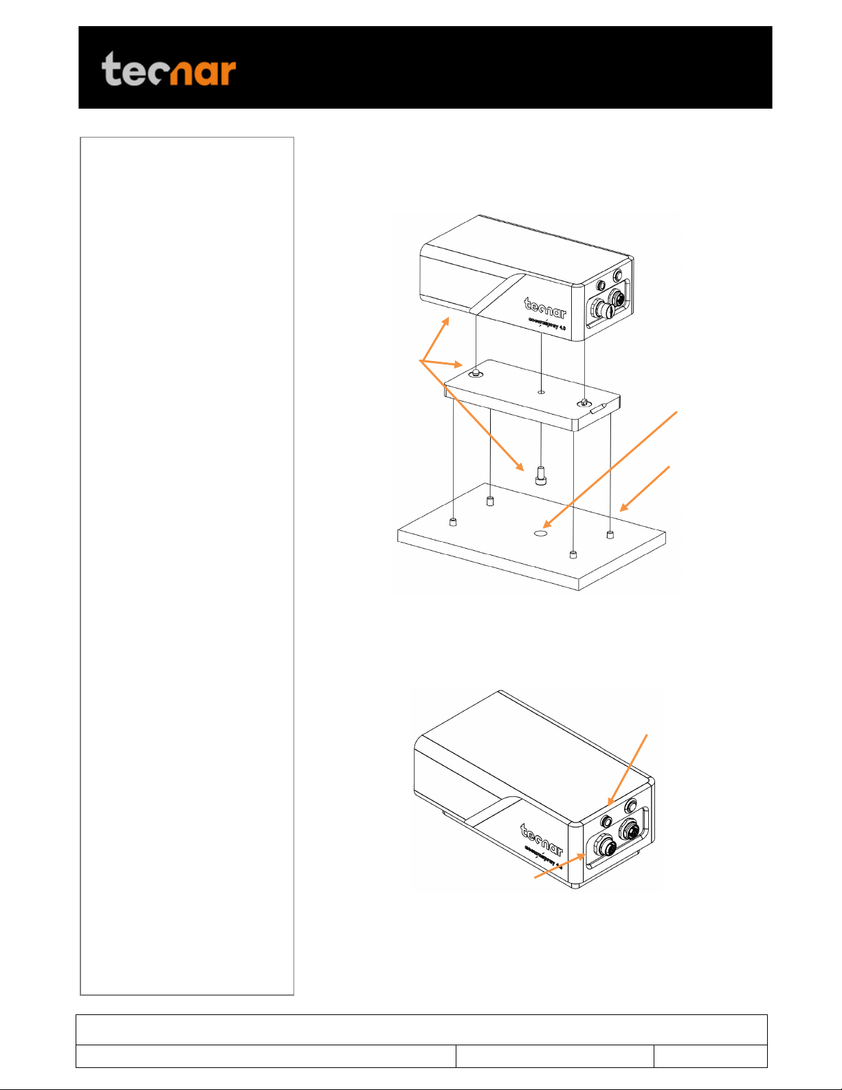
Air supply
Communication cable
Supplied with the
Accuraspray 4.0
Supplied by the user
Provide access
4.1.2.2 Installation procedure
Attach the sensor head mounting plate to your support bracket using the 4
mounting holes.
FIGURE 16 M OUNTING THE SENSOR HEAD
Connect compressed air supply and communication cable to the sensor
head. Pull the other end of the communication cable out of the spray booth.
Connect the air hoses to the booth air supply.
FIGURE 17 SENSOR HEAD INTERFACE
!
Page 32
This document contains information considered proprietary and confidential to Tecnar Automation Ltd
40101-00024-00– Rev E
Revision date: 2019-03-17
Page 32 of 43
User manual Accuraspray4.0
!
4.1.3 INSTALLING THE CONTROLLER
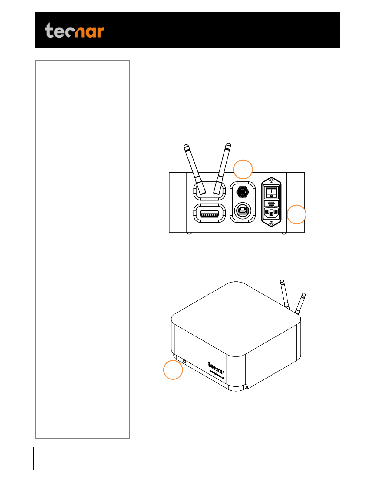
1 2 3
4.1.3.1 Where to install
Install the controller outside the spray booth, ideally, close to the booth
control equipment.
4.1.3.2 Installation procedure
Connect the sensor head communication cable.
Connect the power cable to the controller and into a power socket.
FIGURE 18 CONTROLLER INTERFACE
Flip the Accuraspray controller power switch to ON. Wait until the LED
turns green.
FIGURE 19 CONTROLLER STATUS LED
!
Page 33
This document contains information considered proprietary and confidential to Tecnar Automation Ltd
40101-00024-00– Rev E
Revision date: 2019-03-17
Page 33 of 43
User manual Accuraspray4.0
!
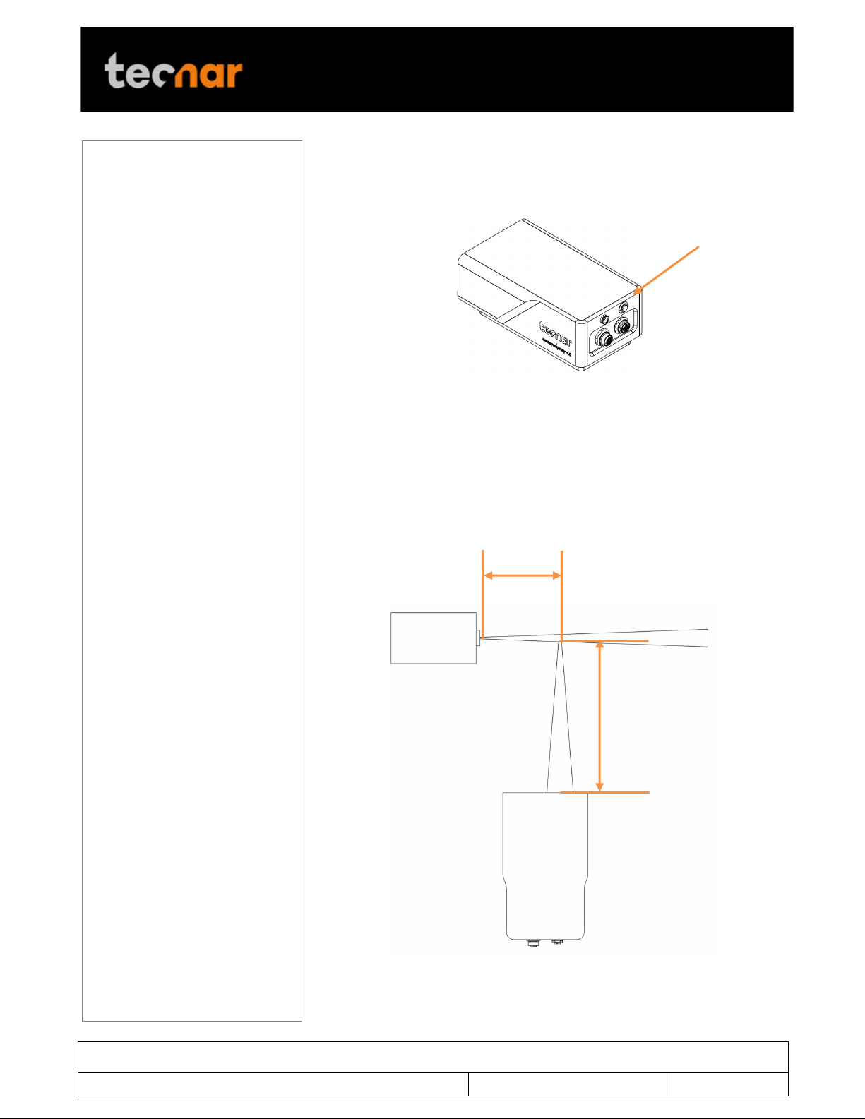
Alignment button
Standard spray distance
Sensor working
200mm
4.1.4 ADJUSTING THE SPRAY GUN POSITION
Activate the alignment beam using the push button located at the back of
the sensor.
FIGURE 20 SENSOR HEAD ALIGNEMENT BUTTON
Bring the spray gun near the sensor head as shown on the schematic below.
The sensor measurement point is normally set to your standard process
spray distance.
The distance between the front of the sensor head and the spray torch axis
should be adjusted to 200mm.
distance
FIGURE 21 SENSOR HEAD WORKING DISTANCE
Save the new position as Sensor Home on the spray gun.
Page 34
This document contains information considered proprietary and confidential to Tecnar Automation Ltd
40101-00024-00– Rev E
Revision date: 2019-03-17
Page 34 of 43
User manual Accuraspray4.0
!
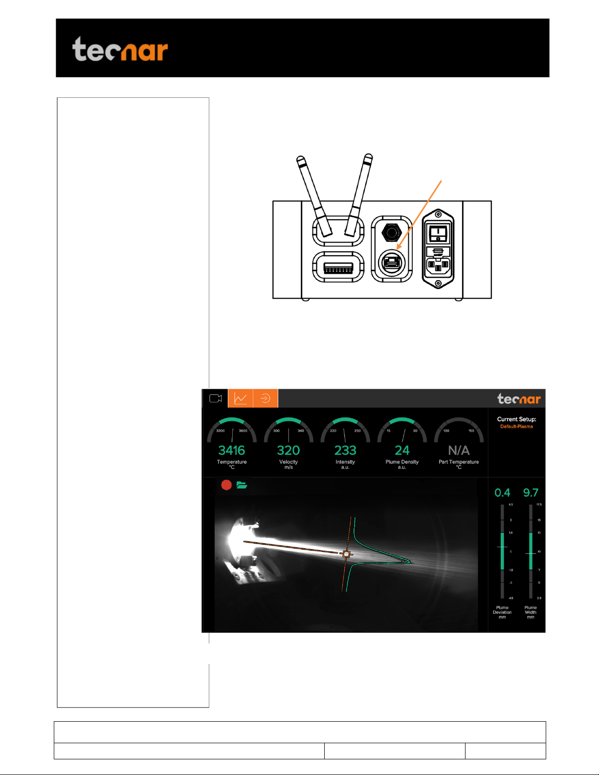
Ethernet port
FIGURE 23 ACCURASPRAY 4.0 USER INTERFACE
4.2 ACCESSING THE USER INTERFACE
Connect your computer or tablet to the controller network using the ethernet
port at the back of the controller.
FIGURE 22 CONTROLLER ETHERNET PORT
Change your computer IP address to: 192.168.101.20 using
255.255.255.0 for the mask.
Open any browser and enter the URL: 192.168.101.150:8004 to connect to
the Accuraspray user interface.
Page 35
This document contains information considered proprietary and confidential to Tecnar Automation Ltd
40101-00024-00– Rev E
Revision date: 2019-03-17
Page 35 of 43
User manual Accuraspray4.0
!
4.3 SETTING UP THE ACCURASPRAY ON A NETWORK (OPTIONAL)
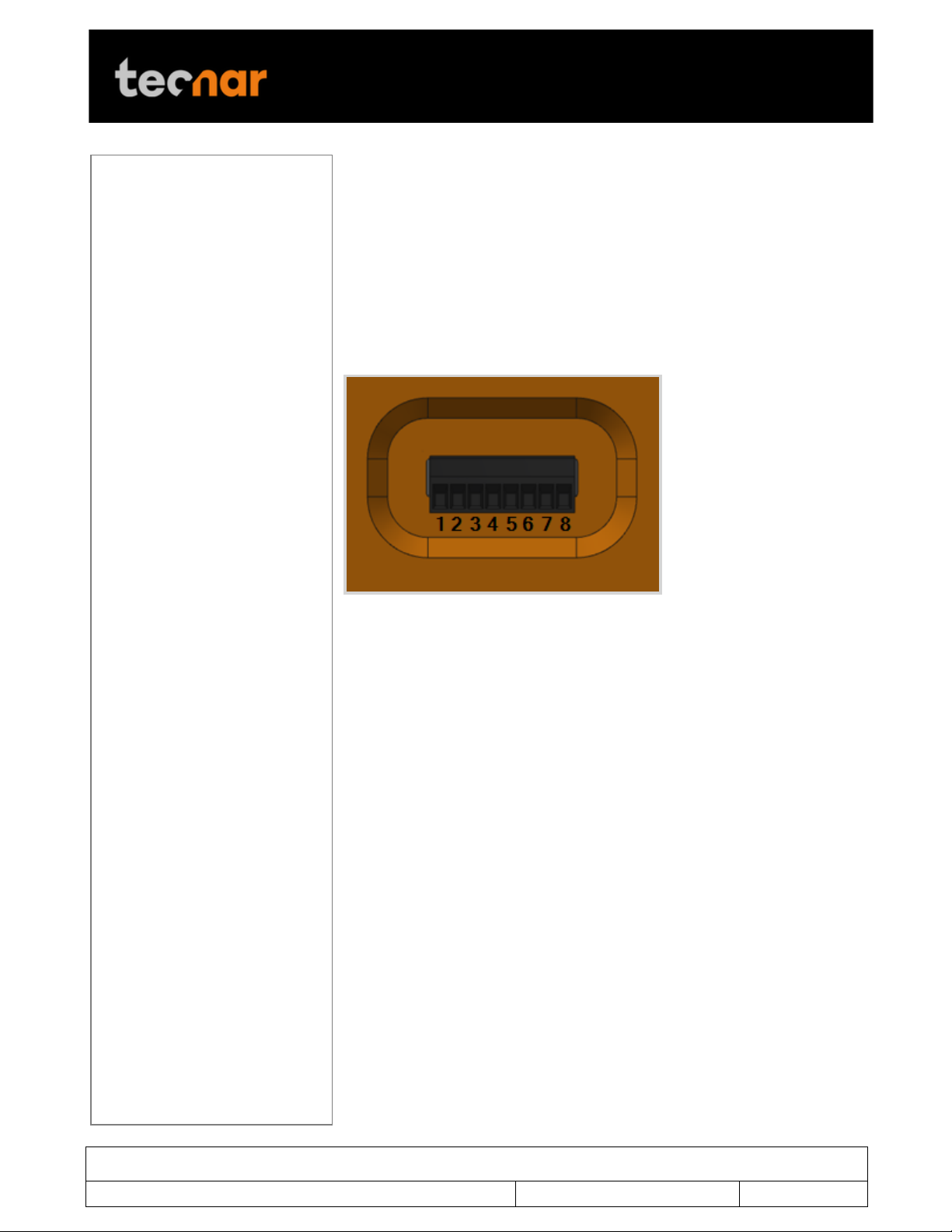
FIGURE 24 I/O PORT
To connect the Accuraspray to your local network you must connect the
controller to the network with an Ethernet cable, wi-fi connection is not
possible.
4.4 CONNECTING THE I/OS (OPTIONAL)
You may remotely control the Accuraspray using the I/Os connections.
To use the I/Os connections, please refer to the following schematic and
descriptions.
! !
Page 36

This document contains information considered proprietary and confidential to Tecnar Automation Ltd
40101-00024-00– Rev E
Revision date: 2019-03-17
Page 36 of 43
User manual Accuraspray4.0
!
Pin
Name
Description
Logic
1
24 VDC IN
Input/Output reference Voltage
+ 2
0 VDC IN
Input/Output reference Voltage -
3
IN 1
Start measurement sequence
(the data acquired by the
Accuraspray will be saved) when
logic is 1 and stop when logic is
0
Logic 1 : 11-24V
above 0VDC IN
Logic 0 : 0-5V
above 0VDC IN
4
OUT 1
Wait for data acquisition.
This output indicates that the
sensor is acquiring its initial data
buffer.
Once the buffer is filled, this
output will fall.
Logic rising edge:
Acquiring initial
buffer
Logic falling edge:
Initial buffer
acquired
5
OUT 2
Measurement valid.
Following the acquisition of the
first buffer this output 1 will be
raised when measurements are
valid.
If the measurements are invalid,
error messages will be displayed
in the user interface and
measurements results should be
ignored.
Logic 1 : 24 VDC IN
Logic 0 : 0 VDC IN
6
OUT 3
All measurements are within the
green zone.
Logic 1 : 24 VDC IN
Logic 0 : 0 VDC IN
7
OUT 4
At least one measurement is
within the yellow zone.
Logic 1 : 24 VDC IN
Logic 0 : 0 VDC IN
8
OUT 5
At least one measurement is
within the red zone.
Logic 1 : 24 VDC IN
Logic 0 : 0 VDC IN
Page 37
This document contains information considered proprietary and confidential to Tecnar Automation Ltd
40101-00024-00– Rev E
Revision date: 2019-03-17
Page 37 of 43
User manual Accuraspray4.0
!
Components
Actions
Frequency
Sensor head
Cleaning the sensor
head windows
Daily
Replacing the sensor
head windows
assembly
When damaged
Sensor head
calibration
Annually
Compressed
air filter
cartridge
Replacing the filter
cartridge
Periodically (see visual
indicator on the cartridge
assembly)
5 MAINTENANCE
5.1 MAINTENANCE SCHEDULE
!
! !
Page 38

This document contains information considered proprietary and confidential to Tecnar Automation Ltd
40101-00024-00– Rev E
Revision date: 2019-03-17
Page 38 of 43
User manual Accuraspray4.0
!
5.2 MAINTENANCE PROCEDURES
5.2.1 CLEANING THE SENSOR HEAD WINDOWS
To ensure accurate measurements, the sensor head windows must be free
of dust, oil and scratches. The sensor head windows must be cleaned after
each measurement procedure.
Tools and materials required:
• Compressed air;
• Lens paper;
• Isopropanol (rubbing alcohol);
Instructions
• Blow clean & dry compressed air on the windows;
• If any marks remain, clean the windows with lens paper. Wipe the paper
across the window in a single motion instead of rubbing back and forth;
• If any marks remain, clean the windows with lens paper and a small
amount of isopropanol. Wipe the paper across the window in a single motion
instead of rubbing back and forth;
• If any marks remain, replace the sensor head window assembly (see next
section).
5.2.2 REPLACING THE SENSOR HEAD WINDOW ASSEMBLY
We recommend you use latex or nitrile gloves when replacing the sensor
head window plate. To avoid damaging the lens, do not use your fingers or
sharp objects.
Tools and materials required:
• Latex or nitrile gloves;
• 2.5 mm Allen key;
• Sensor head window plate (20303-00930-00);
Instructions
• Remove the four M3 screws and carefully remove the window assembly.
• Put the new assembly on the sensor with the air knife at the top (facing
downward). Insert the four M3 screws to secure the plate.
!
Page 39

This document contains information considered proprietary and confidential to Tecnar Automation Ltd
40101-00024-00– Rev E
Revision date: 2019-03-17
Page 39 of 43
User manual Accuraspray4.0
!
Components
Part number
Compressed air filter
cartridge
10201-00599-00
Sensor head windows
assembly
20303-00930-00
5.2.3 CALIBRATING THE SENSOR HEAD
All sensor heads are calibrated at Tecnar before being shipped to the endusers. To ensure accurate measurements, sensor calibration should be
verified every year so that their calibration is NIST-traceable.
You must send the sensor heads to Tecnar Automation Ltd every year for
calibration, contact [email protected]. There is no need to send the
cables and controller.
5.3 RECOMMENDED SPARE PARTS
!
! !
Page 40

This document contains information considered proprietary and confidential to Tecnar Automation Ltd
40101-00024-00– Rev E
Revision date: 2019-03-17
Page 40 of 43
User manual Accuraspray4.0
!
Error code
Description
Actions
2 blinks
The controller did not
connect to the sensor within
2 minutes after the
initialization
Reboot the controller
3 blinks
Internal micro-switch error
Contact Tecnar service
team
4 blinks
Microcontroller error
Contact Tecnar service
team
6 TROUBLESHOOTING
On power-up of the controller, once the sensor is initialized properly, the
back-plate LED will start blinking quickly (3 quick blinks every 5 seconds), it
behaves the same way as a beacon light. This initial blinking indicates that
the electronics components inside the sensor are up and running, and that
the sensor is waiting for the software to connect. Note that the back-plate
LED button is not available during this initialization sequence. Once the
software is connected to the sensor, the LED will stop blinking immediately,
and the back-plate button becomes enabled. Thus, it can now be used for
alignment purposes. The startup time of the controller is usually as fast as
the initialization of the sensor head. Depending on the startup time duration,
the blinking might be hard to notice if the controller connects to the sensor
as soon as it is initialized.
In the event that the initialization sequence is not successful, the LED will
not stop blinking. Instead, it will start blinking more slowly, indicating that the
sensor is now in error state (the LED will be held ON for approximately 1.5
seconds instead of 166 milliseconds, maintaining a 5 second interval in
between the blinks). The back-plate button will remain disabled. Refer to the
troubleshooting section for more information on the LED error codes.
6.1 SECTION TROUBLESHOOTING (LED ERROR CODES)
As mentioned in the operation section, in the case of hardware failure, the
back-plate LED is used as a troubleshooting tool to provide more
information on the system error state. Here is a list of all the possible codes,
descriptions, and troubleshooting actions to be taken.
!
! !
Page 41

This document contains information considered proprietary and confidential to Tecnar Automation Ltd
40101-00024-00– Rev E
Revision date: 2019-03-17
Page 41 of 43
User manual Accuraspray4.0
!
6.2 ERROR REPORTING IN THE USER INTERFACE
Page 42

This document contains information considered proprietary and confidential to Tecnar Automation Ltd
40101-00024-00– Rev E
Revision date: 2019-03-17
Page 42 of 43
User manual Accuraspray4.0
!
Error code
Corrective measures
Invalid velocity
measurement (Low
correlation)
• The sensor head is aimed perpendicular
to the spray plume and is 200mm.
• The sensor head is 200mm away from
the center of the spray plume.
• SPRAY DIRECTION is set correctly.
• The spray plume angle is no more than
± 15°.
Invalid velocity &
temperature
measurements (Signal
level too low)
• The sensor head is aimed at the spray
plume.
• The proper setup has been selected.
• Powder is injected into the spray plume.
• The sensor head windows are clean.
• SIGNAL AMPLIFICATION is set
adequately for your process.
Invalid velocity &
temperature
measurements (Saturated
signal)
• The proper setup has been selected.
• SIGNAL AMPLIFICATION is set
adequately for your process.
Invalid plume width,
plume deviation, plume
intensity & density
measurements (Signal
level too low)
• The proper setup has been selected.
• The sensor head windows are clean.
• EXPOSURE TIME is set adequately for
your process.
Invalid measurements
(Saturated signal)
• The proper setup has been selected.
• EXPOSURE TIME is set adequately for
your process.
Page 43

This document contains information considered proprietary and confidential to Tecnar Automation Ltd
40101-00024-00– Rev E
Revision date: 2019-03-17
Page 43 of 43
User manual Accuraspray4.0
!
!
!
 Loading...