

Maintenance
Manual
Doc. n° 92/115
2nd Issue, September 10th, 2004
1st Revision, October 25th, 2004

Ed
.2
efore flying the aircraft we recommend reading carefully this manual, the flight
B
P92 Echo & P92-S Echo
Maintenance Manual
INTRODUCTION
manual and the engine’s manuals. A thorough knowledge of the aircraft, of its
qualities and of its limitations will allow you to operate with greater safety.
The P92 Echo and P92-S Echo are uncomplicated and sturdy machines whose
features include simple servicing and superior flying qualities. This manual
describes time and modes for correct servicing procedures. Scrupulously following
instructions will insure that your P92 Echo or P92-S Echo will accompany you
dependably for a long time with optimal performance in absolute safety.
This manual consists of 5 sections; a table of contents at the beginning of each
section will allow you to reach quickly any selection.
Information contained in this manual is based on available data at publication time,
possible variations shall be presented with servicing bulletins.
This manual describes correct servicing of parts manufactured by TECNAM and, in
subordinate measure, of the list of components purchased from external suppliers;
for more complete information on individual components it is necessary to refer to
the component’s manufacturer’s manual.
For further information or explanations contact:
COSTRUZIONI AERONAUTICHE
a
1
Traversa via G.Pascoli
TECNAM
s.r.l.
80026 Casoria (NA) - ITALY
081-7583210 081-7584528
Date: Sept. 2004
Page . i

Ed
.2
P92 Echo & P92-S Echo
Maintenance Manual
INTRODUCTION
SECTIONS
General Section A
Inspections and Servicing Section B
Airframe Section C
Powerplant and Propeller Section D
Systems Section E
Date: Sept. 2004
Page . ii
P92 Echo & P92-S Echo
Maintenance Manual
Section A
GENERAL
SECTION A
GENERAL
TABLE OF CONTENTS
1 - DESCRIPTION AND GENERAL CHARACTERISTICS-------------------------------------------- 4
Ed. 2
Page A-1 Date: Sept. 2004

P92 Echo & P92-S Echo
Maintenance Manual
Section A
GENERAL
TABLE I
WING
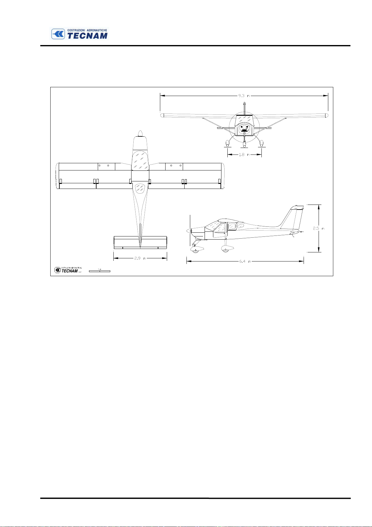
Wing Span 9.3 m
Wing Area 13 m2
Aspect Ratio 6.6
Taper ratio 1.0
Chord 1.4 m
Flap span 1.97 m
Flap chord 0.385 m
Aileron span 1.97 m
Aileron chord 0.385 m
FUSELAGE
Length (overall) 6.4 m
Width max. 1.06 m
Height max. (vertical tail end) 2.5 m
EMPENNAGES
Stabilator Span 2.90 m
Stabilator Area 1.972 m2
Stabilator chord 0.680 m
Vertical Tail Span 1.230 m
Vertical Stabilizer Area 0.720 m2
Rudder Area 0.350 m2
LANDING GEAR
Wheel Track 1.8 m
Wheel Base 1.6 m
Nose Wheel Tire Sava 4.00-6
Main Wheel Tires
WEIGHTS
Maximum Take Off Weight 450 kg
Empty Weight 281 kg
Payload 169 kg
Wing Loading 34.1 kg/m2
Power Loading (Rotax 912 UL) 5.6 kg/hp
Power Loading (Rotax 912 ULS) 4.6 kg/hp
AirTrac A-A1D4
5.00-5
Ed. 2
Page A-2 Date: Sept. 2004

POWERPLANT:
ROTAX 912 UL
Four stroke, four cylinder
Maximum Power 59.6 kW @ 5800 rpm (max. 5 minutes)
Maximum Continuous Power 58 kW @ 5500 rpm
Reduction Gear 1 : 2.27
ROTAX 912 ULS
Four stroke, four cylinder
Maximum Power 73.5 kW @ 5800 rpm (max. 5 minutes)
Maximum Continuous Power 69 kW @ 5500 rpm
Reduction Gear 1 : 2,43
P92 Echo & P92-S Echo
Maintenance Manual
Section A
GENERAL
PROPELLER:
For 912UL: TONINI GT ECHO 92/166/145
Twin blade all-wood ∅ 166 cm, fixed pitch.
For 912ULS: TONINI GT ECHO 92/172/164
Twin blade all-wood ∅ 172 cm, fixed pitch.
Ed. 2
Page A-3 Date: Sept. 2004
1st revision, October 25
th
2004
FUEL
P92 Echo & P92-S Echo
Maintenance Manual
Section A
GENERAL
Fuel grade
Rotax 912 UL
• Min RON 90
• EN 228 Regular
• EN 228 Premium
• EN 228 Premium plus
• AVGAS 100 LL (*)
Rotax 912 UL
• Min RON 90
• EN 228 Premium
• EN 228 Premium plus
• AVGAS 100 LL (*)
Fuel tanks 2 wing tanks integrated within the wing's leading
edge with fuel strainer located in engine cowling
Capacity of each wing tank 35 litres (45 litres – Optional)
Total capacity 70 litres (90 litres – Optional)
(*) Please refer to “Rotax Operator’s Manual”
Oil System
Oil system type Forced, with external oil reservoir
Oil Lubricant specifications and grade are detailed into
the “Rotax Operator’s Manual” and in its related
documents
Oil Capacity: max. 3.0 litres – min 2.0 litres
COOLING
Cooling system: Mixed air and liquid pressurized closed circuit
system
Coolant: Coolant type and specifications are detailed into
the “Rotax Operator’s Manual” and in its related
documents.
Ed. 2
Page A-4 Date: Sept. 2004
P92 Echo & P92-S Echo
Maintenance Manual
Section A
GENERAL
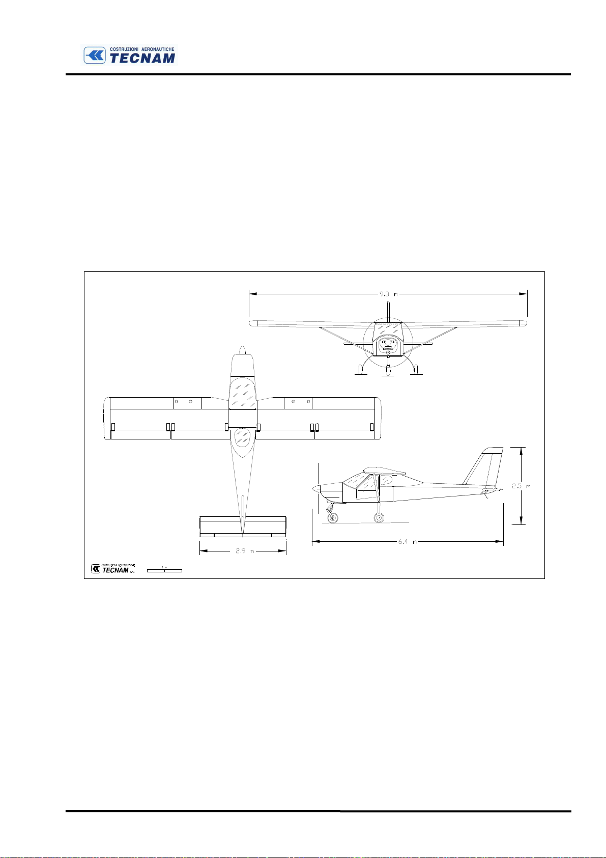
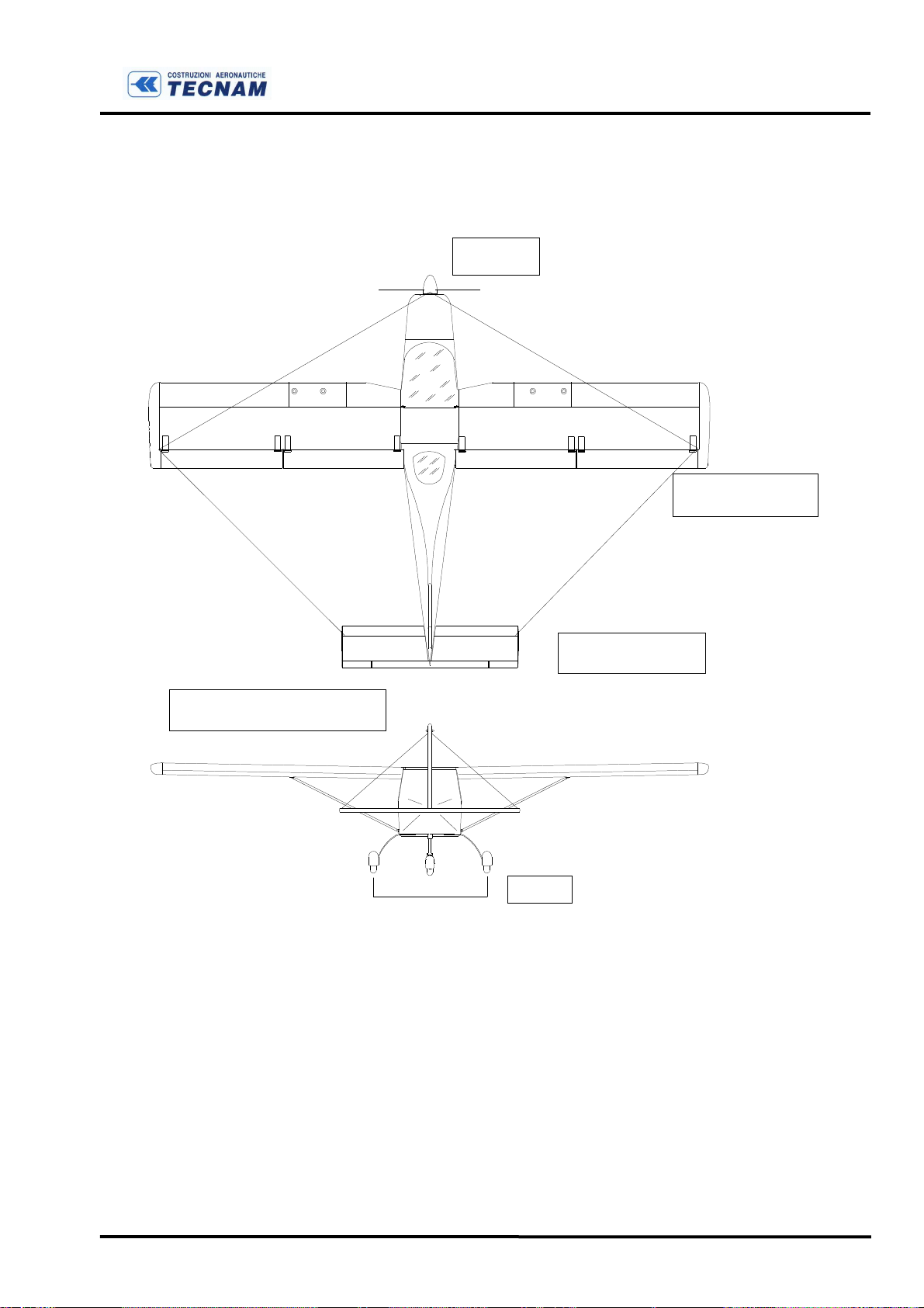
1 - DESCRIPTION AND GENERAL CHARACTERISTICS
The
P92 Echo
structure monoplane with tricycle landing gear and steerable nose gear.
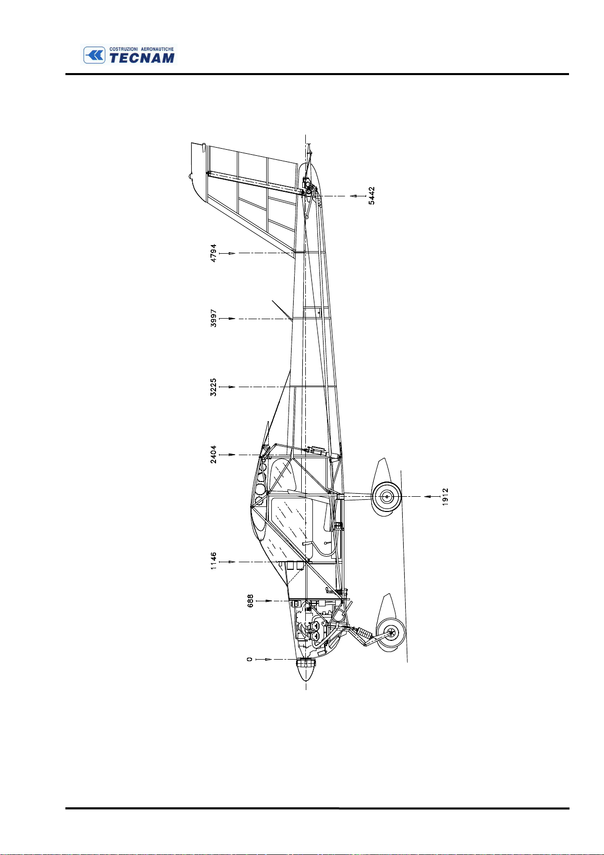
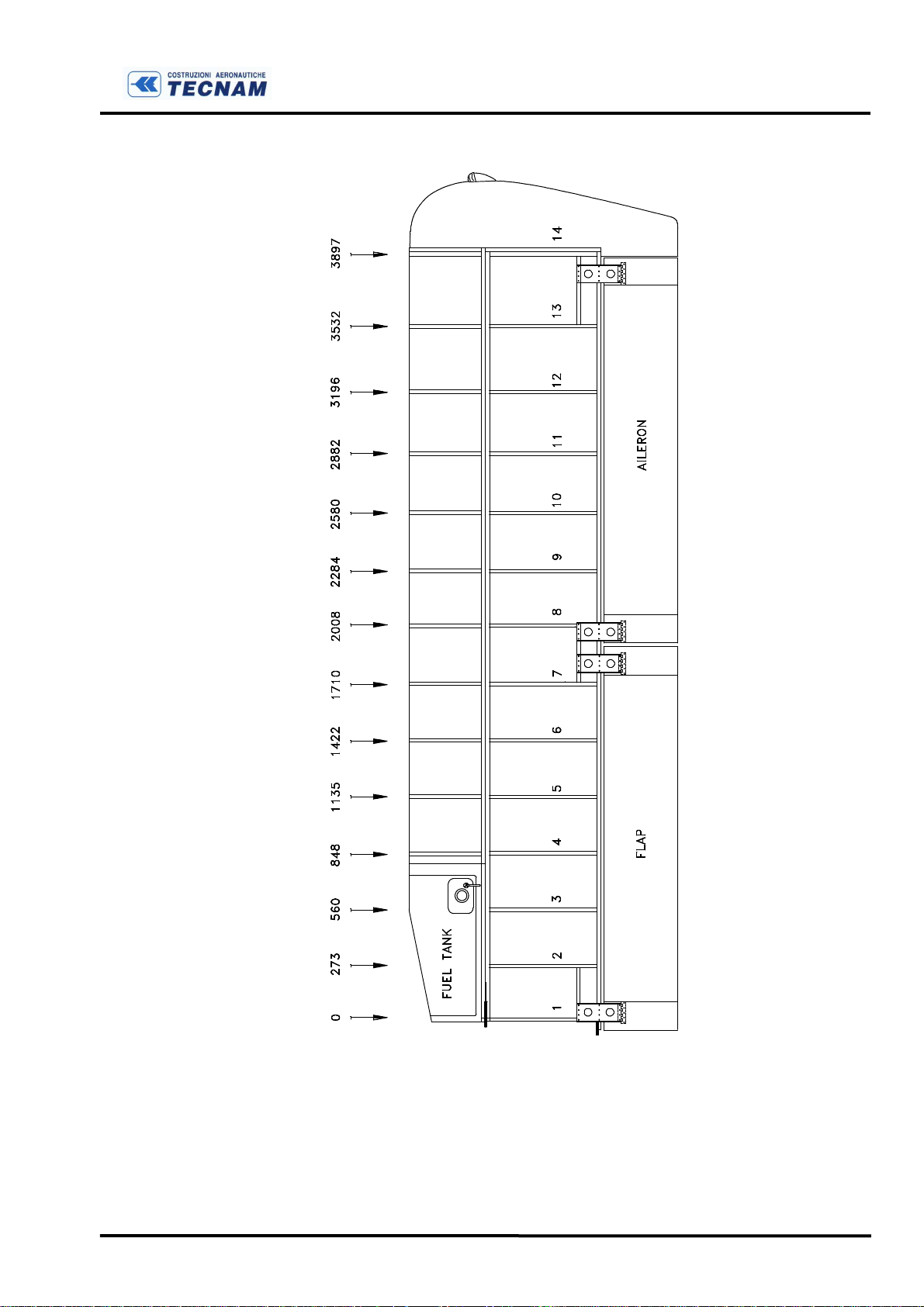
Figure A-1 below shows a Three View drawing of the aircraft (P92-S Echo) while table I
reports main technical characteristics and dimensions; figure A-2 shows a longitudinal
section of the aircraft and figure A-3 shows the wing’s planform view.
P92 Echo
GENERAL VIEW
and
P92-S Echo
are a twin seat, single engine, strutted high wing, metal
F
IGURE
A-1 P92 E
CHO - THREE VIEWS
Ed. 2
Page A-5 Date: Sept. 2004
P92-S Echo
GENERAL VIEW
P92 Echo & P92-S Echo
Maintenance Manual
Section A
GENERAL
F
IGURE
A-1
BIS
P92-S E
CHO - THREE VIEWS
Ed. 2
Page A-6 Date: Sept. 2004
P92 Echo & P92-S Echo
Maintenance Manual
Section A
GENERAL
F
IGURE
Ed. 2
A-2 L
ONGITUDINAL SECTION
Page A-7 Date: Sept. 2004
P92 Echo & P92-S Echo
Maintenance Manual
Section A
GENERAL
F
IGURE
A-3 W
ING’S PLANFORM VIEW
Ed. 2
Page A-8 Date: Sept. 2004

P92 Echo & P92-S Echo
Maintenance Manual
Section B
INSPECTIONS
AND SERVICING
SECTION B
INSPECTIONS AND SERVICING
TABLE OF CONTENTS
1. GROUND HANDLING..........................................................................................................2
2. PARKING AND TIE DOWN................................................................................................2
3. JACKING................................................................................................................................2
4. LEVELING.............................................................................................................................3
5. CONTROL SETTINGS......................................................................................................... 4
6. TRIM-TAB ADJUSTMENT .................................................................................................4
7. AIRCRAFT ALIGNMENT...................................................................................................5
8. WEIGHING AND DETERMINATION OF THE C.G. VERTICAL ................................6
TABLE OF WEIGHTS AND DETERMINATION OF C.G..............................................................7
9. CORROSION PREVENTION..............................................................................................8
10.
SERVICE BULLETINS....................................................................................................9
11.
SERVICING.....................................................................................................................10
12.
LUBRICATION...............................................................................................................11
INTRODUCTION ........................................................................................................................... 11
LUBRICATION POINTS (SEE
FIG.
B-5)........................................................................................12
13.
Ed.2
INSPECTION’S POINT .................................................................................................15
14.
INSPECTIONS................................................................................................................16
FOREWORD...................................................................................................................................16
PERIODIC INSPECTIONS............................................................................................................. 17
Page B-1 Date: Sept 2004
P92 Echo & P92-S Echo
Maintenance Manual
Section B
INSPECTIONS
AND SERVICING
1. GROUND HANDLING
Moving the aircraft on ground is accomplished by pushing on the wing struts close to
wing attachments or by pulling on the propeller blades close to hub. Aircraft can be
steered using the rudder or, for sharp turns, by lowering the tail to raise nose wheel off the
ground. In this case, owing to the favourable CG location, a gentle push on the tail cone
just ahead of empennage surfaces is all that’s needed. Avoid dragging nose wheel
sideways and do not attempt to counter any movement of the aircraft by handling it by its
wing tips.
2. PARKING AND TIE DOWN
As a general precaution for outdoor parking, it is wise to position aircraft into the wind
and to set the parking brakes or chock the wheels if chocks are available.
In severe weather and high wind conditions, aircraft tie-down is recommended. Tie ropes
should be secured to the wing tie-down fittings located at the upper end of each wing
strut. Secure opposite end of ropes to ground anchors. Nose gear fork may be used as
fixing for forward tie-down.
Aircraft control stick should be locked using safety belts to prevent possible wind action
from causing control surfaces to hit end travel.
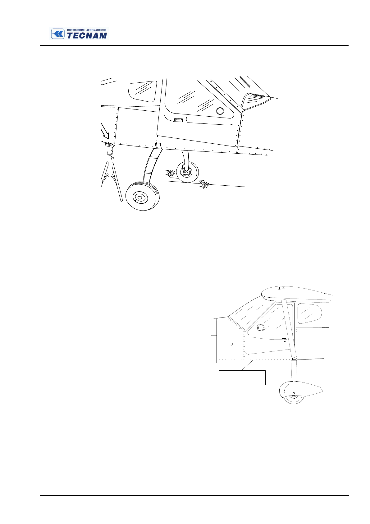
3. JACKING
Given the low empty weight, jacking one of the main gear wheels can be accomplished
even without hydraulic jack. In fact, it is sufficient that one person lifts the wing tip in
proximity of the spar area before the tip, while another person positions a suitably high
support, like a wooden stand or block, under the leaf spring attachment. To avoid
scratching the paint, cover the stand or block with rubber or other suitable material.
In the event the leaf spring must be removed, the stand should be positioned under the
cabin, just ahead of the leaf spring as shown in figure B-1.
CAUTION
As general rule, apply force to aircraft structure only on main structural
elements such as frames, ribs or spars.
Ed.2
Page B-2 Date: Sept 2004
N THE LEVEL
ON THE INSIDE OF THE
CABIN
P92 Echo & P92-S Echo
Maintenance Manual
Section B
INSPECTIONS
AND SERVICING
F
IGURE
B-1 J
ACKING
4. LEVELING
Occasional levelling of aircraft may be necessary to insure proper wing incidence and/or
dihedral or for exact CG location.
The aircraft is levelled when the
lower cabin door sill is horizontal
(see fig. B-2) and the main gear
support girder is horizontal in a
transversal direction. Level the
aircraft using a simple level and
adjust the aircraft’s tilt through
shims placed under wheels or by
regulating tire pressure.
POSITIO
Ed.2
F
IGURE
B-2 L
EVELLING
Page B-3 Date: Sept 2004

P92 Echo & P92-S Echo
Maintenance Manual
Section B
INSPECTIONS
AND SERVICING
5. CONTROL SETTINGS
Adjustment of control surfaces must not exceed travel limits reported in table below. Zero
reference mark for stabilator is on left side of aircraft (see figure below).
AILERONS
STABILATOR Up 16o Down 3o
TRIM (
RUDDER RH 25o LH 25o
FLAPS (
(starting from tip line-up
Stab. at 0o , see fig. below
maximum travel
)
)
)
Up 20o Down 15o
2o 12o
0o 35o
Cable tension should be as follows:
CONTROL CABLE TENSION: 20 daN ± 2 for all
REFERENCE RIVET
± 2o
± 1o
± 1o
± 2o
± 2o
F
IGURE
B-3 S
TABILATOR ZERO REFERENCE
6. TRIM-TAB ADJUSTMENT
Travel adjustment of trim tab on tail plane should be carried out as follows:
• Move stabilator to neutral (0 degrees) and lock in position; (this is accomplished by
aligning the stabilator’s leading edge with the reference rivet located on the left side of
tail cone);
• Turn Master-Switch ON;
• Trim to maximum pitch-up;
• Adjust thread of hinged control rod until tab is deflected downwards 12° (use a
protractor or measure downward displacement of trailing edge - 12° relates to roughly
24mm -);
• Tighten adjustment thread lock-nut and fasten connecting pin of control rod to trim-
tab.
Ed.2
Page B-4 Date: Sept 2004
P92 Echo & P92-S Echo
Maintenance Manual
7. AIRCRAFT ALIGNMENT
Section B
INSPECTIONS
AND SERVICING
A
UPPER/REAR RIVET ON ALUMINIUM SKIN.
i.e. The rivet in common between the fin's rear
spar and the upper rib.
C
B
G
SPINNER BACK
PLATE UPPER
POINT
FIRST RIVET BETWEEN THE
TUBULAR SPAR AND THE
C'
OUTERMOST RIB
A'
LAST RIVET ON THE LOWER
SIDE OF THE REAR WING
SPAR
Ed.2
C
C'
Main Wheels
F
Axle Line
F'
F
IGURE
B-4 R
EFERENCES FOR ALIGNMENTS
Page B-5 Date: Sept 2004
P92 Echo & P92-S Echo
Maintenance Manual
Section B
INSPECTIONS
AND SERVICING
Datum length in mm
A -B 5030
A’-B 5030
A -C 4365
A’-C’ 4365
C -G 1860
C’-G 1860
F -F’ 1880
± 25
± 25
± 25
± 25
± 20
± 20
± 20
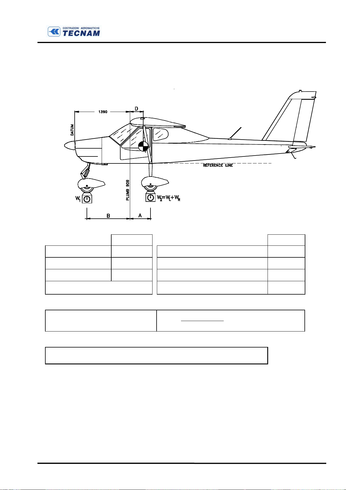
8. WEIGHING AND DETERMINATION OF THE C.G. VERTICAL
U
SE FOLLOWING GUIDELINES
a. Carry out weighing procedure inside hangar
b. Remove any objects inadvertently left on board aircraft
c. Align nose wheel
d. Drain fuel
e. Oil, hydraulic fluids and coolants at operating levels
f. Move seats to most forward position
g. Flaps retracted (0°)
h. Control surfaces in neutral position
i. Position scales (min. capacity. 200 kg) under each tire
:
Ed.2
L
EVELLING
a. Level the aircraft (see paragraph 4)
W
EIGHING
a. Record weights of individual scales
b. Calculate empty weight
D
ETERMINATION OF
C.G.
a. Dropping a plumb bob tangent to the wing’s leading edge, (in the un-
tapered section of the wing, at about one meter from the root), trace a
reference mark on floor.
b. Repeat operation on other wing.
c. Connect the two reference marks with a taut line
d. Measure distances between reference line and landing gear axes
e. Recorded data allows determination of C.G. location and aircraft’s
moment (see following table)
Page B-6 Date: Sept 2004
WAW
B
We
⋅−⋅
P92 Echo & P92-S Echo
Maintenance Manual
TABLE OF WEIGHTS AND DETERMINATION OF C.G.
Section B
INSPECTIONS
AND SERVICING
Kg meters
Wheel weight front
“ “ LH
“ “ RH
W2=WL+WR=
W1 =
WL =
WR =
Distance from bob to nose wheel.
Distance from bob to LH wheel
“ “ RH “
Distance average (AL+ AR)/2
A
=
L
AR =
A =
B =
Empty weight W
e =W1 + W2
=
D
=
2 1
=
___________meters
CG position as wing chord %
De% = De / 1.4 ⋅ 100 =
Ed.2
Page B-7 Date: Sept 2004
P92 Echo & P92-S Echo
Maintenance Manual
Section B
INSPECTIONS
AND SERVICING
9. CORROSION PREVENTION
It is important to keep the aircraft clean and to remove any collection of corrosive agents
such as oil, grease, dregs and other foreign matter. To avoid damage to finish do not use
polishing detergents.
Original or equivalent corrosion prevention must be re-applied after any alteration or
repair.
If any trace of corrosion is detected it should be removed as soon as possible and part
should be immediately treated to prevent further corrosion.
(a) For steel parts, with the exception of highly stressed components or stainless steel, it is
possible to use abrasives, power brushes, steel brushes if operated manually and steel
wool.
Removing corrosion byproducts from highly stressed steel components (main gear steel
spring) requires particular care.
(b) For aluminium parts, treatment consists in mechanically removing as much as
possible corrosion byproducts, applying corrosion inhibitor and replacing original finish.
Steel wool, emery or steel brushes (unless stainless steel) along with other highly abrasive
material should not be used since steel or emery particles become embedded in the softer
material causing corrosion.
After cleaning surface corrosion, parts must be treated with anti-corrosion finish.
Ed.2
Page B-8 Date: Sept 2004
P92 Echo & P92-S Echo
Maintenance Manual
Section B
INSPECTIONS
AND SERVICING
10. SERVICE BULLETINS
The following table must report all servicing bulletins pertaining to the aircraft’s
operating life.
NR. TITLE TYPE
Ed.2
Page B-9 Date: Sept 2004
P92 Echo & P92-S Echo
Maintenance Manual
Section B
INSPECTIONS
AND SERVICING
11. SERVICING
For scheduled servicing on engine Rotax 912, please refer to the Rotax documentations.
The list below includes only primary engine maintenance operations.
D
AILY
1.
Pitot and static ports - Check for obstructions (see section E);
2.
Oil - Check oil level in reservoir located on firewall.
3.
Coolant - Check coolant level in overflow reservoir located on firewall;
4.
Fuel strainer - Drain off any water and sediment by opening tap and
collecting an amount of fuel at least equal to cup’s capacity.
5.
Fuel tank vents - Check for obstructions.(see section E)
EVERY
100
HOURS
6. Flange carburettor - Visually inspect rubber flange connecting carbs to
engine.
7. Battery - Check level of electrolyte.
8. Engine oil - Change engine oil and replace filter element (refer to
Operator’s Manual of ROTAX 912); initially after first 25 hours.
9. Brake fluid - Check level of brake fluid in the master cylinder located below
the left seat. Add fluid as needed using MIL H5606 standard type UNIVIS
J43.
10.Fuel filter – Check and eventually clean the fuel filter of the electric pump
(if installed).
11.Fuel line and carburettor air filter - Visually inspect fuel lines. Remove
filter and clean accurately. Repeat operation more often in dusty conditions.
If aircraft is equipped with carb heat system, scoop filter shall in any case be
replaced (automotive type air filter: Autobianchi Y10).
12.Propeller - Check attachment bolts for integrity, tightening torque (18 Nm)
and safetying, initially after the first 25 hours.
Ed.2
Page B-10 Date: Sept 2004

P92 Echo & P92-S Echo
Maintenance Manual
13.Gyro instrumentation (if installed)- In case of incorrect readings of vacuum
system, clean or replace central filter and, if needed, adjust vacuum valve.
14.Flap and stabilator - Check visually for condition and for absence of crack,
wear etc. of Dacron covers.
A
S NEEDED
14.
Tires - Check condition and maintain proper tire pressure.
12. LUBRICATION
INTRODUCTION
Section B
INSPECTIONS
AND SERVICING
Periodic lubrication of moving parts insures proper operation and extends parts’ life
considerably.
Lubrication type, points and intervals are indicated below.
Avoid excessive lubrication as this may cause external surfaces of hinges and bearing to
collect dirt and dust.
If part is not lubricated using a grease gun, grease part by hand removing excess.
To grease main gear wheel bearings, first remove thrust bearings from wheel hubs, then
clean surface using solvent, apply grease and re-assemble.
NOTE - Use grease type MIL-G-3278 or equivalent (e.g. ESSO
BEACON 325).
Ed.2
Page B-11 Date: Sept 2004

P92 Echo & P92-S Echo
Maintenance Manual
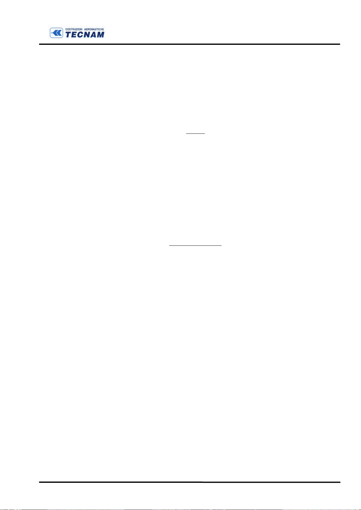
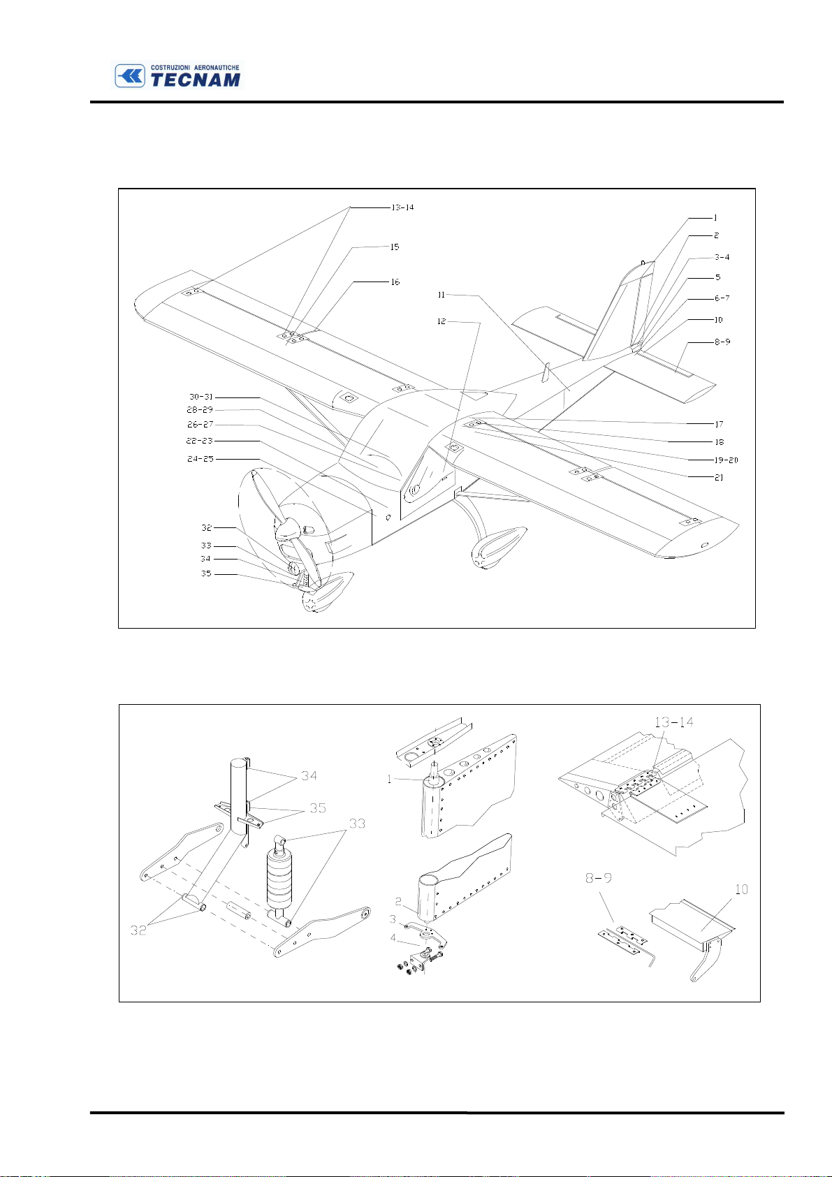
LUBRICATION POINTS (SEE fig. B-5)
1-2 Rudder hinges
3-4 Rudder control cable terminals
5 Stabilator control rod terminals
6-7 Stabilator support bearings
8-9 Trim-tab hinges
10 Tab control push-rod terminals
11 Stabilator pass-through rod
12 Stabilator control rod (inside cabin)
13-14 Aileron hinges
15 Differential ailerons hinges
16 Aileron control pushrods
17 Aileron control rods pass-trough
18 Flaps control pushrods
19-20 Flaps torque-tube support
21 Flap actuator terminals
22-23 Rudder pedals support
24-25 Rudder pushrods and cable terminals
26-27 Brake lever support
28-29 Control stick lever and support
30-31 Aileron control pulleys
32 Nose gear fork attachment hinge
33 Shock absorber attachment hinge
34 Nose gear strut attachment hinge
35 Steering pushrod terminals
Section B
INSPECTIONS
AND SERVICING
Ed.2
Grease door hinges and adjustable seat rails when necessary.
Page B-12 Date: Sept 2004
P92 Echo & P92-S Echo
Maintenance Manual
Section B
INSPECTIONS
AND SERVICING
F
IGURE
F
IGURE
B-5 L
UBRICATION POINTS
B-6 E
VERY
100
HOURS
Ed.2
Page B-13 Date: Sept 2004

P92 Echo & P92-S Echo
Maintenance Manual
Section B
INSPECTIONS
AND SERVICING
Ed.2
IGURE
F
B-7 E
VERY
100
HOURS
Page B-14 Date: Sept 2004

P92 Echo & P92-S Echo
Maintenance Manual
Section B
INSPECTIONS
AND SERVICING
13. INSPECTION’S POINT
Inspection points that are not in plain view may be accessed through specific portholes
and/or removal of panels or fairings as detailed below:
1.
Portholes on wing underside - access to aileron differential
bellcrank.
2.
Upper strut-wing fairing (if present) - inspection of strut
attachment.
3.
Lower strut-wing fairing (if present) - inspection of strut
attachment.
4.
Tail cone underside portholes - access to stabilator control; vertical stabilizer forward attachment; -inspection of structure and
rudder control cables.
5.
Battery porthole - access to battery compartment.
6.
Tail cone end fairing - access to stabilator torque tube and
attachments to control lever; attachment of vertical stabilizer aft
spar; rudder bellcrank; trim actuator and pushrods.
7.
Aft cabin bulkhead and luggage compartment floor - inspection
of aft fuselage section and attachments; inspection of stabilator
control system and of cable pulleys for rudder control; access to flap
actuator; access to aileron control cable turnbuckles.
8.
Forward cabin side panels - access to half-wings’ forward
attachment; access to fuel line tank outflow.
9.
Cabin overhead panel (if present) - access to connection between
cabin’s cable circuit and wing’s pushrod system for aileron control;
10.
Dashboard panel (if present) - access to instrumentation.
11.
Engine cowling - access to engine and related systems; access to
main components of electrical; access to nose gear strut and steering
assembly.
12.
Propeller spinner - access to propeller hub.
Ed.2
Page B-15 Date: Sept 2004

P92 Echo & P92-S Echo
Maintenance Manual
Section B
INSPECTIONS
AND SERVICING
14. INSPECTIONS
FOREWORD
TECNAM deems inspection schedule outlined below compulsory for the aircraft’s
operational safety over an extended period of time. Described servicing requirements
pertain to operation in non-extreme climatic conditions.
For the Rotax 912 engine, it is compulsory to adhere to maintenance requirements as
reported in the engine’s Operator’s Manual.
Inspections are to be carried out as follows:
A. Inspections for airworthiness before first flight of day as specified in
Flight Manual.
B. Periodic Inspection 100 hours as specified in the previous sections.
C. Special inspections, added to normal periodic.
D. Singular inspection, when aircraft has been exposed to fortuitous events
that may have damaged one or more of its components.
If aircraft is rarely used, inspection at 100 hours must be performed yearly.
Inspections and checks, unless specifically indicated, apply to the following
S
TRUCTURES IN GENERAL
- Condition of panel covers, ribs, frames, stringers
etc., absence of cracks, deformation, rivet slackening, corrosion and any
other apparent sign of damage.
M
OVING PARTS
absence of
- Lubrication, security of attachment, safetying of bolts,
EXCESSIVE
tolerance, proper adjustment, proper travel, condition
of attachments and hinges, absence of corrosion, deformation, rivet
slackening, cleanliness.
F
LUID LINES AND HOSES
- Absence of leaks, cracks, dents, chafing, proper
radius, deterioration.
B
OLTS AND ATTACHMENTS
- Proper tightening and safetying, absence of cracks
or nicks, damage to thread, wear and excessive tolerance.
Ed.2
Page B-16 Date: Sept 2004

P92 Echo & P92-S Echo
Maintenance Manual
Section B
INSPECTIONS
AND SERVICING
PERIODIC INSPECTIONS
Every porthole, fairing, panel etc. shall be removed to allow for inspection.
Procedures listed in SERVICING are included in the inspections.
Instructions for actions following inspection are detailed in specific sections pertaining to
the aircraft group or system.
N
ATURE OF INSPECTION
ENGINE COMPARTMENT
Remove cowling and check for fuel, oil and coolant leaks; clean
1
engine compartment
Check density of battery electrolyte
2
Visually inspect electric pump connections
3
Visually inspect engine mount and silent-blocks attachments
4
Visually inspect exhaust manifold, muffler and heat exchanger
5
Visually inspect air intake and carburetor feed circuit
6
Visually inspect coolant reservoir, radiator and circuit line
7
Visually inspect oil reservoir, radiator and circuit line
8
INSPECTION
I
NTERVALS
(
HRS
)
Special
100
(a)
Page B-17 Date: Sept 2004
Ed.2
Check wires and electrical connections (low and high tension)
9
Check carburetor control and throttle movement
10
Check idle and carburetor sync. 600
11
Clean electric fuel pump filter
12
(a) Every 100h or more frequently in warm climate.

P92 Echo & P92-S Echo
Maintenance Manual
Section B
INSPECTIONS
AND SERVICING
N
ATURE OF INSPECTIONS
FUEL SYSTEM
Check rigid circuit lines for integrity and wetness
1
Check shutoff valves
2
Rinse tanks and clean exit filters 1200
3
Check vent floats 600
4
Check electric fuel pump
5
FLIGHT CONTROLS
Check cables, terminals, pulleys and turnbuckles for integrity and
1
proper condition of aileron and rudder control
Check pushrod terminals, lever hinge bushings, stabilator control
2
pass-through
INSPECTION
INTERVALS
100
(
HRS
Special
)
Check pushrod terminals and aileron control pass-through
3
Check flaps pushrod terminals
4
Check flaps actuator for integrity and play, attachment of
5
terminals and electrical connections
Check torque tube, levers and attachments for flaps control
6
Check resin control lever for trim actuator 600
7
Check trim control levers and pushrods for integrity and play
8
Check rudder pedals for integrity and play
9
Check control stick group for integrity and play
10
General check for proper tension level for control cables 600
11
600
Ed.2
Page B-18 Date: Sept 2004

P92 Echo & P92-S Echo
Maintenance Manual
Section B
INSPECTIONS
AND SERVICING
N
ATURE OF INSPECTIONS
MOVING SURFACES
Visually inspect integrity of dacron wrap-around for ailerons and
1
stabilator; watch for cracks, chinks, etc.
Visually inspect and check integrity of wrap-around paneling for
2
rudder and flaps.
Check integrity and play of flaps and aileron hinges
3
Check integrity and play of stabilator attachments
4
Check integrity and play of trim-tab hinges
5
Check play and proper fastening of stabilator tubular spar
6
Check integrity of balance weight support
7
ISPEZIONE
INTERVALS
(HR)
Special
100
Check integrity and play of rudder lever and hinges
8
WING
Visually check general condition of wrap-around skin and rivets
1
Disconnect wings from fuselage and check condition of
2
attachments and for possible play
Check condition of spar and wing structure through dedicated
3
openings
1200
600
Ed.2
Page B-19 Date: Sept 2004

5
P92 Echo & P92-S Echo
Maintenance Manual
Section B
INSPECTIONS
AND SERVICING
N
ATURE OF INSPECTIONS
FUSELAGE and EMPENNAGE
Visually check general condition of wrap-around skin and rivets
1
Inspect cabin truss for deformations and corrosion 600
2
Check seat rails and stops and safety belt attachments
3
Check internal condition of tailcone structure 600
4
Check attachment between vertical stabilizer and tail beam 600
5
Check integrity and fastening of stabilizer support assy 600
6
Check integrity and general condition of transparent surfaces and
7
doors
Check electric circuit wiring and antennae attachments from
8
inside of tailcone
100
ISPEZIONE
INTERVALS
(HR)
Special
600
MAIN LANDING GEAR
Check brake system (reservoir, master cylinder, lines and
1
calipers)
Replace brake pads 600(a)
2
Visually check steel spring struts, connection clamp and
3
fastening of bolts
Remove legs and check for proper curvature and integrity 1200
4
Inspect main wheels for condition and fastening
Remove wheels, clean and grease wheel bearings 600(b)
6
Check fairing integrity and attachments
7
(a) when brake pad thickness is below 2.4 mm
(b) initially at 100 hours
Ed.2
Page B-20 Date: Sept 2004

P92 Echo & P92-S Echo
Maintenance Manual
Section B
INSPECTIONS
AND SERVICING
N
ATURE OF INSPECTIONS
NOSE GEAR
I
Inspect support truss for gear strut and attachment hinges
1
Check proper movement of steering levers and pushrods
2
Check integrity and play of strut-to-fork hinge attachment 600
3
Check shock hinge attachments 600
4
Check shock for general condition and state of rubber disks
5
Inspect wheel for condition and fastening
6
Remove wheel, clean and grease wheel bearings 600(c)
7
Remove nose gear assy for general safety check and inspection 1200
8
INSPECTION
INTERVALS
100
(HR)
Special
Check integrity of fairing and fairing attachments
9
INSTRUMENT PANEL
L
General inspection of operation of flight and engine instruments
1
Check generator charge
2
Check compass alignment 48
3
Check calibration of airspeed indicator and altimeter 1200
4
Check operation of avionic instrumentation (if installed)
5
Check operation of switches and breakers
6
(c) initially at 100 hours.
months
Ed.2
Page B-21 Date: Sept 2004

P92 Echo & P92-S Echo
Maintenance Manual
SUMMARY OF REFERENCE VALUES
T
ORQUE SETTINGS FOR CONNECTION BOLTS AS A FUNCTION OF THEIR LEG DIAMETER
Bolts resistance category 8.8
= 3.1 Nm
∅ 4
= 10.4 Nm
∅ 6
= 24.6 Nm
∅ 8
Section B
INSPECTIONS
AND SERVICING
Warning: propeller attachment bolts must be
fastened to 18 Nm value even though they have a ∅ 8
diameter.
C
ONTROL CABLE TENSION (FOR BOTH AILERON AND RUDDER )
T
IRE PRESSURE
VALUE : 20 dN ± 2 dN
:
NOSE 15 PSI
MAIN 23 PSI
(1.0
BAR
(1.6
BAR
)
)
C
ONTROL SURFACES TRAVEL RANGE
Ailerons
Stabilator
Trim
Up 20° down 15° ±2°
Up 18° down 3° ±1°
2°, 12° ±1°
Rudder
Flaps
RH 25° LH 25° ±2°
0° -35° ±2°
Ed.2
Page B-22 Date: Sept 2004

P92 Echo & P92-S Echo
Maintenance Manual
Section C
AIRFRAME
SECTION C
AIRFRAME
TABLE OF CONTENTS
1 - INTRODUCTION ......................................................................................................................1
2 - WING........................................................................................................................................... 2
3 - REMOVAL AND RE-INSTALLATION OF A WINGS.........................................................3
2.1 - F
LAP CONTROL (SEE FIG.
4 - HORIZONTAL TAIL................................................................................................................6
5 - VERTICAL TAIL....................................................................................................................... 9
6 - FUSELAGE...............................................................................................................................11
7 - LANDING GEAR.....................................................................................................................13
7.1 M
AIN GEAR WHEEL REMOVAL (SEE FIG.
7.2 R
EMOVAL OF MAIN GEAR WHEEL BEARING (SEE FIG
7.3 N
OSE GEAR
7.4 R
EMOVAL OF THE NOSE GEAR FAIRING (IF INSTALLED) AND WHEEL (SEE FIG
.................................................................................................................................17
C-3)..................................................................................................... 3
C14)..............................................................................15
.C15)...........................................................16
.C-17).....................17
Ed.2
Page C-1 Date: Sept. 2004

P92 Echo & P92-S Echo
Maintenance Manual
1 - INTRODUCTION
The airframe consists of the following main components as shown in figure C-1:
1) Wings
2) Fuselage
3) Empennage
4) Landing gear
5) Powerplant
Section C
AIRFRAME
F
IGURE
C-1 M
AIN AIRFRAME COMPONENTS
In case it becomes necessary to disassemble the aircraft for transport or other reason, it is
necessary to read section C carefully.
Ed.2
Page C-1 Date: Sept. 2004

P92 Echo & P92-S Echo
Maintenance Manual
Section C
AIRFRAME
2 - WING
Each wing is connected to the fuselage by means of two pin attachments and a single strut
brace per side.
Wings are constructed of a central light alloy torsion box; leading edge is attached to front
spar where metal fuel tank (10) and wing-fuselage plastic union (9) find collocation. Flap
(1) and aileron (2) are attached by two hinges each to rear spar.
The torsion box, as shown in figure C-2 and with reference to numbers in parenthesis,
consists of a main spar (4) and a secondary spar (5) that make up its front and rear walls
respectively and of a series of ribs (6); metal panels cover the entire structure. Front and
aft spars are equipped with wing-to-fuselage attach fittings (7). Wing-to-strut attach fitting is located approximately at the middle of main spar (8). Both aileron and flap hinges
are made of “piano-hinges" type MS 20001-4 for direct attachment to spar of moving surfaces.
F
IGURE
Ed.2
C-2 W
ING STRUCTURE
Page C-2 Date: Sept. 2004

P92 Echo & P92-S Echo
Maintenance Manual
Section C
AIRFRAME
Aileron is constructed of a single light alloy spar to which are joined box type leading
edge and ribs; entire structure is covered with “Dacron” synthetic cloth. Flap has the same
aileron structure and is covered aluminum panels.
Wing tips (3) are molded epoxy resin, fiberglass reinforced.
3 - REMOVAL AND RE-INSTALLATION OF A WINGS
Procedure for removal of a wing and strut is as follows.
A.
Drain fuel tank using drain tank and closing opposite side tank fuel circuit;
B.
Remove access panel located under the wing allowing access to fuel line and disconnect, plug pipe ends on both wings;
C.
Disconnect transparent scavenge small pipe only LH wing;
D.
Disconnect wires for navigation lights (if present);
E.
Disconnect flap control (see fig. C-3) by removing roller bearings (7) linking pushpull rods (6) with flap control plate;
F.
Remove aileron control (see fig. C-4) by disconnecting pins (4) linking small bar (3)
with rods (5).
G.
While supporting the wing’s end, release strut’s upper pin, then release lower pin and
remove strut.
H.
While supporting the wing from below the root area, release the two wing-to-fuselage
attachment pins. To expedite release of aft pin, keep flap lifted, then remove wing.
I.
Replace pins.
Reverse above procedure for reinstallation paying close attention to tighten strut’s bolts to
recommended value (M8 bolt torque 24.6 Nm).
2.1 - Flap control (see fig. C-3)
Flap control system is push-rod type. The torque tube (1), connects the two moving surfaces and hinges to supports (2) rigidly attached to fuselage structure. Rotation is transmitted through a push-rod (3) whose position is controlled by an electric linear actuator
(4) governed by a switch on dashboard. Jack stops are adjusted by moving the switches
locate inside the flap actuator body (4).
Two push-pull rods (6) are connected to the ends of the torque tube (see fig. C-3) (1) allowing quick inspection owing to favorable location between wing and fuselage.
The two push-pull rods controlling flap movement feature an extendible linkage just before the roller bearings allowing trailing edge line-up.
Ed.2
Page C-3 Date: Sept. 2004

P92 Echo & P92-S Echo
Maintenance Manual
Section C
AIRFRAME
F
IGURE
C-3 F
LAP CONTROL
2.2 - Aileron control (see fig. C-4)
Aileron control system uses rigid rods inside wing and steel cables inside cabin.
Flight control system inside cabin includes three pairs of pulleys which transmit movement from the two control sticks (1) linked by a rod (2), to a small bar (3) located cabin
overhead in correspondence to the main rods from the wings. The main rods ends are
joined using two pins (4) to the small bar ends. The two main rods (5), are routed through
the ribs and are attached at bellcrank lever system (6) push-pull rod (7). The push-pull rod
crosses the wing’s secondary spar and features roller bearings and extendible linkage to
regulate length.
Ed.2
Page C-4 Date: Sept. 2004

P92 Echo & P92-S Echo
Maintenance Manual
Section C
AIRFRAME
F
IGURE
C-4 A
ILERON CONTROL
To remove aileron, disconnect one end of push-pull rod and remove pins from hinges.
Reverse above procedure to reinstall aileron insuring that, with stick vertical, the aileron’s
trailing edge is aligned with wing’s trailing edge.
Through access panels located on wing’s bottom, check that the bellcrank lever is in neu-
tral position, i.e. the inside arm at right angle with spar axis. To remove wings, disconnected release short bar (3) that close steel cable system, to main rods (5) by pins (4). The
steel cable system is designed to insure proper cable tension without the need to check
each time the half-wings are removed. It is however recommended that periodic checks
be carried out and proper tension applied by acting on the two turnbuckles (8) located behind the cabin’s rear panel.
Also check periodically that pulleys rotate freely and pins tolerance for entire transmission is within standards (ref. Section B).
Ed.2
Page C-5 Date: Sept. 2004

P92 Echo & P92-S Echo
Maintenance Manual
Section C
AIRFRAME
If control stick should feel unusually hard, reduce cable tension as this may be the primary cause for malfunction (ref. Section B); also check that parts of the link system positioned under seats are properly greased.
If control stiffness persists, check integrity of bellcranks or pulleys and insure that cable
has not come off pulleys.
Alignment of moving surfaces with half-wing must be done using outboard trailing edge
as reference. Further lateral corrections (aircraft leans to one side) may be carried out adjusting trim tab located on left aileron trailing edge.
4 - HORIZONTAL TAIL
Horizontal tail is an all moving type, that is, the stabilizer and elevator form a single, uniform plane called stabilator which rotates about an axis normal to fuselage centre line at
the desired pitch setting.
The stabilator structure (see fig. C-5) is constructed of a light alloy tubular spar (1) to
which a series of ribs (2) and an light alloy leading edge (3) are riveted. Entire structure is
Dacron covered.
A trim tab (4) provides stick force adjustment and longitudinal compensation through an
electric actuator controlled by pilot. Tab is split in two halves interconnected at the support brackets (5) and attached to the stabilator through four external hinges (6) that allow
immediate inspection.
Figure C-5 S
TABILATOR
Ed.2
Page C-6 Date: Sept. 2004

P92 Echo & P92-S Echo
Maintenance Manual
Section C
AIRFRAME
Each half plane engage on steel tubular hub that escape to fuselage, locked in place by
means of pins (7). Taking up possible tolerance make by means of two riveted grains (8).
To remove each stabilator, disconnect the two halves of the tab from each other and from
the control rod, remove pins (7), then remove half-planes. To avoid cover damage during
operation, handle parts by their rigid components.
Reverse operation for reinstallation slightly greasing the inside of the torque tube (1) to
facilitate insertion and gently tapping parts into position being careful not to deform outward ribs.
The stabilator control system is push-rod type (see fig. C-6) and is controlled from the
cabin via the control sticks. Control is transmitted through a push-pull rod (1) linked to a
bellcrank (2) and a shaft (3) that runs through (4) the tail cone, transmit movement to
stabilator’s hub lever (5).
All significant transmission element such as bellcranks, pushrods, supports and hinges
can be easily accessed and inspected.
F
IGURE
C-6 S
TABILATOR CONTROL
If unusual tolerance is found along transmission, replace parts presenting excessive wear.
The stabilator hub (see fig. C-7) consists of, a steel tube (1) with welded horn assembly
(2) and attachment for stabilator control shaft (3). Counterweight (4) is at the end of an
arm joined control lever by means of two bolts. Arm entering tail stock through lightening hole of the last tail cone ordinate.
Longitudinal trim is controlled by a switch located on cabin tunnel or (optional) by two
push-buttons mounted on the stick handle; position is, in any case, monitored via an indicator located on dashboard. Control activates the linear actuator (5) connected to supports
Ed.2
Page C-7 Date: Sept. 2004

P92 Echo & P92-S Echo
Maintenance Manual
Section C
AIRFRAME
(6) and plates (7). Actuator’s motion is transmitted to an adjustable push-pull rod (8)
through a bellcrank (9).
To remove stabilator’s hub disconnect electric actuator frame assembly (7), from support
(6), release aft bellcrank assembly (3) then release plates (2) from brackets(6).
Ed.2
F
IGURE
C-7 H
ORIZONTAL TAIL CONTROL SYSTEM
Page C-8 Date: Sept. 2004

P92 Echo & P92-S Echo
Maintenance Manual
Section C
AIRFRAME
5 - VERTICAL TAIL
The vertical tail is an all-metal light alloy structure (fig. C-8). Rudder tip is fiberglass
with cut-outs for navigation and strobe light.
The vertical stabilizer consists of a twin spar with wrap-around load bearing skin paneling. An attachment plate to the fuselage tail cone (1) secures the stabilizer’s front spar to
the lower tip while the rear spar is extended to attach directly onto the last tail cone ordinate (2).
The rudder consists of an aluminum alloy torque tube (3), formed sheet metal ribs (4) and
sheet metal panel cover (5) held in place by rivets.
F
IGURE
C-8 V
ERTICAL STABILIZER, RUDDER AND SUPPORTS
The hubs (6) and (7) are to the ends of rudder provide by means of bushings (8) hinged
rudder with vertical stabilizer. The lower hinge assembly is attached to a bellcrank controlled by cables from rudder pedals.
Ed.2
Page C-9 Date: Sept. 2004

P92 Echo & P92-S Echo
Maintenance Manual
Section C
AIRFRAME
To the upper ends rudder torque tube is joined steel arm with, to the end, counterweight
and rotate freely onto vertical stabilizer tip. In case tip isn’t profile two plastic fairing
(one of this removable) counterweight fitting in slot.
To remove rudder, after disconnected little stern and flying tail (see § 4), disconnect cables from bellcrank, remove lower bearing and release rudder with downward motion.
Control system layout (fig. C-9) is steel cable join rudder control lever with rudder pedals lever.
Rudder pedals (1) direct two transmission connection rod (3) close circuit rudder control
and pass on the movement to the nose wheel leg via two threaded stem ball and socket
joint adjustable push rods connections.
Cable tension must be checked periodically and adjusted to proper value (Tension = 20
daN ± 2) using the turnbuckles (4); condition and smooth operation of pulleys (5) must
also be checked. To access levers and rudder pedals support, remove cabin’s central tunnel; for speedier operation remove seats from railings.
F
IGURE
C-9 R
UDDER CONTROL
Ed.2
Page C-10 Date: Sept. 2004

P92 Echo & P92-S Echo
Maintenance Manual
Section C
AIRFRAME
6 - FUSELAGE
The forward fuselage consist of a steel truss survival cell (fig. C-10) and of a light alloy
semi-monocoque structure attached to the cabin’s aft section.
Rear (fig. C-11) consist in a light alloy semi-monocoque structure. Four longitudinal
structural elements trestlework connection allow. Tail beam rear end are two strut brackets of tail horizontal plane (2) and attachments vertical plane longeron on ordinate.
Framework shown in figure C-10 below, details location of attachment points for halfwing (1), aft structure (2), brace-strut (3), main gear (4), engine mount (5), flap torque
tube (6), stabilator bellcrank (7), throttle (8) and pulleys for cable driven aileron control
(9). Seat supports and safety harness attachment points are also shown.
Ed.2
F
IGURE
C-10 C
ABIN FRAMEWORK
Engine mount is constructed of steel tubing and secured to fuselage with four-point attachment. Bolts travel through bushings welded on mount, cross firewall and exit through
other bushings welded to fuselage framework. Nose wheel truss is integral part of engine
mount.
Page C-11 Date: Sept. 2004

P92 Echo & P92-S Echo
Maintenance Manual
Section C
AIRFRAME
Figure C-11 Fuselage aft section
Cabin access is through two doors constructed of light alloy square tubing. A fiberglass
structure, external, shaped for better comfort is riveted. Both doors feature spring lock
door handles with inside safety latch.
Seats are make up in metal tubing framework with fabric covered padding. Seats can be
adjusted along railings attached to fuselage using release lever positioned just below seat.
Floor matting is light alloy covered by a thin layer of carpeting.
Entire fuselage, wing and other exposed surfaces are finished with a highly resistant
weatherproofing synthetic coating.
Wash using only soapy water and chamois.
NOTE
A
LL PARTS IN PERSPEX MATERIAL MUST NEVER BE DUSTED DRY, BUT WASHED WITH LUKEWARM SOAPY
WATER. IN ANY CASE, NEVER USE, ON THIS KIND OF SURFACE, PRODUCTS SUCH AS GASOLINE, ALCOHOL
OR ANY KIND OF SOLVENT
.
Ed.2
Page C-12 Date: Sept. 2004

P92 Echo & P92-S Echo
Maintenance Manual
Section C
AIRFRAME
7 - LANDING GEAR
The main landing gear (see fig. C-12) consists of two special steel leaf-spring struts (1)
for elastic cushioning of landing loads.
Gear struts are attached to fuselage underside at main framework girder.
Two shims (2,3) are positioned between gear struts and fuselage; struts are held in place
by light alloy tie brackets (4) by means of bolts (5) and bolt (6) to the end.
F
IGURE
C-12 M
AIN GEAR
Wheels are cantilevered on gear struts and feature hydraulically actuated disk brakes (see
fig. C-13) controlled by a lever (1) located on cabin tunnel between seats. Main gear
wheels adopt Air Trac A-A1D4, 5.00-5 tires inflated at 23 psi (1.6 bar). Hydraulic circuit
shut-off valve (2) is positioned between seats and, when off, activates parking brake function obtained pulling lever.
Braking is simultaneous on both wheels. Control lever (1) activates pump (3) that features
built-in brake fluid reservoir (4); check valve (5) secure brake function when activated,
unintentionally, parking brake.
Ed.2
Page C-13 Date: Sept. 2004

P92 Echo & P92-S Echo
Maintenance Manual
Section C
AIRFRAME
F
IGURE
C-13 H
YDRAULIC BRAKE CIRCUIT
Removal of single gear strut is as follows:
A.
Remove cabin seats by pushing them forward and off the railings;
B.
Raise aircraft onto supports;
C.
Close the shut-off valve (ref.2 in fig. C-13) without pull the brake lever (1); Do not
activate brake lever (1) during the operation
D.
Disconnect hydraulic brake circuit by unscrewing upper latch of external line on fuselage underside. Cap lines temporarily to prevent fluid spill;
E.
Loosen bolts (part 5 fig. C-12) holding aluminum bracket (part 4 fig. C-12) at leaf
springs lateral attachment;
F.
Release inboard leaf-spring pin (part 6 fig. C-12) by unscrewing locknut on cabin
girder;
G.
Remove spring-steel strut pulling horizontally.
Reinstall using reverse procedure. It is however necessary to eliminate any trapped air:
once the circuit is closed and fluid in reservoir is at normal level, bleed air through small
valve provided. For best results pump hydraulic fluid through small valve allowing
trapped air to escape through open reservoir.
If verify brake function decrease, provide check and substitution, eventually, main gear
pads.
For this procedure refer to Periodic Inspection Table in Section B pertaining to main
landing gear.
Ed.2
Page C-14 Date: Sept. 2004

P92 Echo & P92-S Echo
Maintenance Manual
7.1 Main gear wheel removal (see fig. C14)
Removal of a single wheel is carried out as follows:
• Landing gear
A.
Lift aircraft (see sect. B).
B.
Disengage parking brake.
C.
Remove fairing (1, if installed) by loosening three rear screws (2) and the frontal
screw (3).
D.
Remove the small screw (4) located on the aluminum support
E.
Remove hub ring nut (5)
F.
Grab tire with both hands and pull.
Section C
AIRFRAME
6
1
2
5
4
3
F
IGURE
C-14 R
EMOVAL OF MAIN GEAR WHEEL
Ed.2
Page C-15 Date: Sept. 2004

7.2 Removal of main gear wheel bearing (see fig.C15)
Removal of a wheel bearing (taper roller bearing) becomes necessary when eccessive resistance occurs during wheel motion. Procedure is as follows:
A.
Remove the fairing (1)
B.
Unscrewing (4), remove the aluminum support use to fix the fairing.
C.
Unscrew the hub ring nut (5).
D.
By the use of a screwdriver, remove the hub washer and the dust-shield ring.
E.
Grab tire (6) with both hands and pull.
F.
Extracting the wheel the taper-roller bearing will be also removed.
Clean bearing accurately using an appropriate solution and wipe wheel rim side. Grease
using FIAT ZETA2. Reverse procedure for mounting. Insert washers and felt by sliding
them perpendicular to hole.
P92 Echo & P92-S Echo
Maintenance Manual
Section C
AIRFRAME
3
5
1
6
6
5
4
2
F
IGURE
Ed.2
C-15 R
EMOVAL OF MAIN WHEEL BEARING
Page C-16 Date: Sept. 2004

P92 Echo & P92-S Echo
Maintenance Manual
Section C
AIRFRAME
7.3 Nose gear
The nose gear (fig. C-16) is attached to the engine mount with two hinges (1) and is
equipped with a Sava 4.00-6 type tire.
Steering motion is transmitted from the pedals through two steering tubes that are attached to the nose gear strut by means of two brackets (2) welded to the strut.
Gear fork is made up of light alloy plates (4) & (5) and a spacer (6); it hinges on the strut
leg and is braced by a rubber-disc shock absorber (3).
F
IGURE
C-16 N
OSE GEAR ASSY
7.4 Removal of the nose gear fairing (if installed) and wheel (see fig.C-17)
To remove the nose gear fairings (if installed) proceed as follows:
A.
To remove front portions of fairing (5 & 6) loosen the screws (2) and (3)
B.
Remove the two fairings (6) and (5).
C.
To remove the rear upper fairing (4) loosen the screws (1)
D.
Unscrew nuts (7) and remove washer from wheel axle
E.
Unscrew bolt (8) in gear lever housing.
F.
Remove the rear fairing (9)
Reverse procedure to reinstall. Avoid damage to fiberglass fairing by not tightening
screws excessively.
Ed.2
Page C-17 Date: Sept. 2004

P92 Echo & P92-S Echo
Maintenance Manual
To remove nose wheel proceed as follows:
A.
Remove the fairings (5) (6) and (9)
B.
Loosen bolts (10), (11) and (13)
C.
Detach the two wheel forks (12) from each other.
D.
Remove wheel axle
E.
Remove the wheel (13)
Section C
AIRFRAME
F
IGURE C - 17 REMOVAL OF NOSEGEAR FAIRING
S
UMMARY OF TIRE INFLATION PRESSURE
Nose tire
Main tire
15 psi 1.0 bar
23 psi 1.6 bar
Ed.2
Page C-18 Date: Sept. 2004

P92 Echo & P92-S Echo
Maintenance Manual
Section D
POWERPLANT and
PROPELLER
SECTION D
POWERPLANT and PROPELLER
TABLE OF CONTENTS
1 - POWERPLANT..........................................................................................................................2
1.1 C
OWLING
1.2 P
OWERPLANT MAIN FEATURES
2 - GENERAL SERVICING PROCEDURES...............................................................................4
2.1 I
DLE SPEED SYNCHRONIZATION
2.2 O
RDINARY SERVICING
3 - PROPELLER..............................................................................................................................4
3.1 P
ROPELLER REMOVAL
3.2 P
ROPELLER INSTALLATION
3.3 P
ERIODIC INSPECTION
......................................................................................................................................2
......................................................................................................3
.....................................................................................................4
...................................................................................................................4
...................................................................................................................4
............................................................................................................4
...................................................................................................................5
Ed.2
Page D-1 Date: Sept. 2004

P92 Echo & P92-S Echo
Maintenance Manual
Section D
POWERPLANT and
PROPELLER
1 - POWERPLANT
1.1 Cowling
Powerplant cowling consists of two parts: fiberglass nose section and light alloy panel on
top and all fiberglass bottom.
Top cowling is easily removed by releasing four latches, two on each side.
Removal of lower portion is just as easy by quick release of two side pins and two latches
located on bottom. Figure D-1 below shows cowling version featuring ram intake and
landing light.
Before removing cowling, disconnect landing light wiring and ram intake air hose from
heat exchanger (optional).
If any cracks are detected, immediately drill stop holes at crack ends. Air circulation is
provided by front openings in nose section and by an outflow area on the underside by the
firewall.
Ed.2
IGURE
F
D-1 E
NGINE COWLING
Page D-2 Date: Sept. 2004

P92 Echo & P92-S Echo
Maintenance Manual
Section D
POWERPLANT and
PROPELLER
1.2 Powerplant main features
The installed powerplant is a Bombardier-Rotax type 912 horizontally-opposed fourcylinder, one central camshaft with pushrods and OHV. Other features include liquid
cooled cylinder heads and ram air-cooled cylinders. Prop drive is via reduction gear.
Electric starter, integrated AC generator and mechanical fuel pump are standard.
Technical data:
912UL 912ULS
- Maximum power 81 hp (59.6 kW) 98.6 hp (73.5 kW)
- rpm @ maximum power 5800 rpm 5800 rpm
- Bore 79.5 mm 84 mm
- Stroke 61 mm 61 mm
- Displacement 1211 cm3 1352 cm3
- Compression ratio 9.0 : 1 10.5 : 1
- Firing order 1-4-2-3 1-4-2-3
- Direction of rotation of
cw from pilot’s perspective cw from pilot’s perspective
propeller’s shaft
- Fuel
Please refer to:
Rotax Operator’s Manual
Please refer to:
Rotax Operator’s Manual
- Reduction ratio 1 : 2.273 1 : 2.4286
F
IGURE
D-2 I
NSTALLED ENGINE WITH CARB HEAT SYSTEM
1st revision, October 25th 2004
Ed.2
Page D-3 Date: Sept. 2004

P92 Echo & P92-S Echo
Maintenance Manual
Section D
POWERPLANT and
PROPELLER
2 - GENERAL SERVICING PROCEDURES
2.1 Idle speed synchronization
With the exception of idle speed synchronization, no other carburetor regulations are
required. Fuel mixture is controlled and set by manufacturer and requires no further
adjustment.
2.2 Ordinary servicing
For all servicing operations refer to the Engine Operator’s Manual furnished by the
engine’s manufacturer and furnished along with the present manual.
3 - PROPELLER
The GT propeller is manufactured by “Fratelli Tonini” and is all-wood, with composite
reinforced leading edge and blade protective finished with special lacquer coating.
3.1 Propeller removal
To remove propeller use the following procedure:
A.
Remove screws holding spinner dome to spinner bulkhead.
B.
Remove safetying.
C.
Remove bolts that secure prop to hub.
After removal, do not lay propeller down on its tip but always lay flat and away from
sources of humidity, heat or, in any case, away from areas subject to excessive
temperature change.
3.2 Propeller installation
To install propeller, follow procedure below insuring propeller is correctly aligned with
hub before tightening bolts:
A.
Carefully clean hub area insuring no oil traces are present;
B.
Check bolts for cracks, rust, proper thread and cleanliness;
C.
Check spinner bulkhead for cracks or deformations;
D.
Check spinner for cracks and deformations;
E.
Install spinner bulkhead and prop;
F.
Insert washers and fasten locknuts (bolt torque = 18 Nm);
G.
Safety all bolts;
H.
Install spinner.
Ed.2
Page D-4 Date: Sept. 2004

P92 Echo & P92-S Echo
Maintenance Manual
Section D
POWERPLANT and
PROPELLER
After correct installation of propeller, let the engine run for a few minutes and, after
turning it off, carry out a further inspection (tightness, overall state, etc.).
F
IGURE
D-3 P
ROPELLER INSTALLATION
3.3 Periodic inspection
Refer to specific subsection in the Periodic Inspection Schedule of Section B.
For further information refer to the “Operator’s and Servicing Manual for GT
Propellers” furnished by the propeller’s manufacturer.
Ed.2
Page D-5 Date: Sept. 2004

SYSTEMS
P92 Echo & P92-S Echo
Maintenance Manual
Section E
SECTION E
SYSTEMS
TABLE OF CONTENTS
1 - FUEL SYSTEM ..........................................................................................................................4
2 - INSTRUMENTATION ..............................................................................................................5
2.1 - E
NGINE INSTRUMENTATION
3 - PITOT AND STATIC SYSTEM ...............................................................................................8
4 - EXHAUST MANIFOLDS..........................................................................................................9
5 - CARBURETOR HEAT AND CABIN HEAT (optional) .........................................................9
6 - BRAKE SYSTEM.....................................................................................................................11
6.1 - D
RAINING AND REPLACING BRAKE FLUID
6.2 - R
EPLACING BRAKE PADS
........................................................................................................7
..................................................................................11
...........................................................................................................12
Ed.2
7 - ELECTRICAL SYSTEM.........................................................................................................13
8 - EMERGENCY PARACHUTE SYSTEM (optional)..............................................................15
Page E-3 Date: Sept. 2004

SYSTEMS
P92 Echo & P92-S Echo
Maintenance Manual
Section E
1 - FUEL SYSTEM
The fuel system (see Fig. E-1) consists of two metallic fuel tanks (1) located in the wing’s
leading edge after wing-fuselage union. Each fuel tank has 35 liters capacity (optional 45
liters). On the upper external is refueling’s cap (2), bay (3) for float (4) chamber and fuel
tank bleed (5). Metal cover plate (6) may be removed for inspection of tank interior that
assembly riveted and puttied with dope gasoline resistant. Return line discharged flange
(7) of fuel system on the left fuel tank rear wall placed. At each fuel tank outlets are present (and serviceable by specific port holes) fuel mesh filters (8).
Ed.2
F
IGURE
E-1 F
UEL SYSTEM
Diaphragm mechanical pump (13), engine connected, stoking provide by means flexible
pipelines come to the fuel tank and across cabin vertical rods, easily accessible, after disassembled plastic structural. On the same cabin vertical rods are circuit on-off valve (9),
one for each fuel tank, easily accessible to the pilot. Circuit link with union tee in correspondence of the firewall, and then to drainage bowl (10), located left upper side in the
engine bay, visible through an upper cowling port.
Page E-4 Date: Sept. 2004

SYSTEMS
P92 Echo & P92-S Echo
Maintenance Manual
Section E
Downstream respect to the gascolator is located a fuel filter (11) built in an electric fuel
pump (12) and then the mechanical (13). Mechanical pump feeds the fuel manifold (14);
its left branch feeds the left carburetor. In derivation a tee connector (16) with restrictor
feed the fuel pressure gauge (15). The rear branch of the ”X” manifold (14) is connected
to the fuel return line (17). In case of mechanical pump failure, electrical pump feed is
available.
Return tube (17) engage in pipe fitting (18) located
on the fire-wall and then by means a thin transparent
tube return at the LH fuel tank.
Disassembled wing is necessary disconnect return
tube by means pipe fitting (19). For release of pipe
fitting’s little tube push in direction to the base
knurled flange. For coupling to the tube insert in
your seat.
Periodically check the fuel tank vent (5) to ensure
that their openings are unobstructed; repeat inspection more frequently if operating in dusty conditions.
It is recommended, for inspection purposes, to use a
small rubber tube to blow through the vent clearing
possible obstructions.
F
IGURE
E-2 G
ASCOLATOR
Drain gascolator daily (see Fig. E-2) using the spring tap (2). Unscrew ring nut (1) for
disconnect bowl and accede at wire mesh filter (4), use particular care at don’t damage
seal (3) and spring (1).
2 - INSTRUMENTATION
The instrument panel, realized in light alloy (see Fig. E-3), is imaginatively divided in
three sections. The left section holds flight control instruments, the right section holds
engine controls and the central section holds eventual communication and navigation instruments.
Ed.2
On lower part of instrument panel are the following:
• Magneto switches and switches for navigation lights, landing light and strobe light if
installed;
Page E-5 Date: Sept. 2004

SYSTEMS
P92 Echo & P92-S Echo
Maintenance Manual
Section E
• flap switch and circuit protection breakers;
• throttle knobs.
Individual instruments may be removed using particular care in disconnecting wiring,
tubing or other linkage as the case applies.
When installing instruments, follow recommendations below:
A.
Do not over-tighten bolts as plastic instrument casing may break.
B.
Insure hoses are free of any foreign matter and that no tight radius turns are present as
this may choke hose or cause malfunction.
C.
Insure proper grounding and tightening of all electrical instruments.
Ed.2
F
IGURE
E-3 I
NSTRUMENT PANEL
Repair, calibration or overhaul of instruments must be carried out only by specialized stations.
Page E-6 Date: Sept. 2004

SYSTEMS
P92 Echo & P92-S Echo
Maintenance Manual
Section E
2.1 - Engine instrumentation
- An electric tachometer is installed;
- An electric oil temperature indicator is installed. The sensor is located on the oil pump
tube and is marked with “TO” on the pump flange.
F
IGURE
E-4 S
ENSORS FOR PRESSURE AND OIL TEMPERATURE
- An oil pressure instrument is installed. See fig. E-4 for sensor location.
- Cylinder head temperature sensors are located on cylinders 2 or 3 and are linked with
relative instrumentation.
- LH and RH fuel level sensors.
Ed.2
Page E-7 Date: Sept. 2004

SYSTEMS
P92 Echo & P92-S Echo
Maintenance Manual
Section E
3 - PITOT AND STATIC SYSTEM
Referring to figure E-5, system consists of a pitot tube (1) mounted on left wing strut and
two static ports (2) connected in parallel (3) and located on left and right side of fuselage
just ahead of door frames. Flexible plastic tubing connect pitot and static ports to pressure
instruments.
Servicing the system is easy and is carried out in accordance with Section B; simply remove tubes from instruments and blow air in tube in port direction and never viceversa,
clearing possible obstructions and checking line condition.
Check visually and more frequently pitot tube on left strut (1) and static ports (2) clearing
possible obstructions.
Ed.2
F
IGURE
E-5 P
ITOT AND STATIC SYSTEM
For safety reasons and to ensure correct airspeed readings, it is important to check the pitot system for leaks adopting the following procedure:
Fasten a piece of rubber hose approximately 30 centimeters long to the pitot tube, close
off the opposite end of the hose and slowly roll it up until the airspeed indicator shows
cruise speed. Constant reading is an indication of no leak in system.
CAUTION
Avoid blowing air through pitot or static ports, as this causes
immediate damage to the airspeed indicator.
Page E-8 Date: Sept. 2004

SYSTEMS
P92 Echo & P92-S Echo
Maintenance Manual
Section E
4 - EXHAUST MANIFOLDS
With reference to figure E-6, exhaust manifolds (1) are flanged to the engine and join the
muffler (2) separately. The muffler also works as a heat exchanger (3) for carb and cabin
heat (optional).
The exhaust system must always be checked for possible cracks. Close attention must be
given to the heat exchanger system which should be totally disassembled for inspection as
cracks would allow noxious fumes to be mixed with cabin air.
F
IGURE
E-6 E
XHAUST MANIFOLDS
5 - CARBURETOR HEAT AND CABIN HEAT (optional)
Two different systems are available:
• C
ABIN HEAT ONLY
This heat system (see Fig. E-7) consists of the above mentioned heat exchanger (3), of
an intercept valve (4) and of an outflow hatch (1) located in rudder bar proximity, and
(optional) two defogging otuflow openings (2).
The intercept valve, located externally on lower part of firewall is controlled by a
round knob located on lower left side of dashboard.
• C
ARBURETOR HEAT AND CABIN HEAT
Carburetor heat is controlled by a valve located in the airbox that switch This system is
designed to direct carb air intake from scoop and manifold located on top portion of
Ed.2
Page E-9 Date: Sept. 2004

SYSTEMS
P92 Echo & P92-S Echo
Maintenance Manual
Section E
firewall. Using a central valve (air valve in fig. E-7) hot air from heat exchanger may
be deviated towards carburetors.
The valve, is controlled by a round knob located centrally on dashboard.
The heating system does not require particular servicing except for periodic check of heat
exchanger and of intercept valve whose faulty closure may cause unwanted heat to enter
cabin.
Ed.2
Figure E-7 C
ARBURETOR HEAT AND CABIN HEAT SYSTEMS
Page E-10 Date: Sept. 2004

SYSTEMS
P92 Echo & P92-S Echo
Maintenance Manual
Section E
6 - BRAKE SYSTEM
The brake system (see fig. E-8) consists of a brake fluid reservoir (4), a master cylinder
(3) and two disc brakes; an intercept valve activates parking brake (2).
Braking action is through a lever (1) located on cabin tunnel between seats. Hydraulic circuit intercept valve is also located between seats and, when closed with lever pulled,
keeps circuit under pressure and aircraft’s parking brake on. It is also installed a checkvalve (5) that provides braking action even if the parking brake valve (2) is shut.
Ed.2
Figure E-8 B
6.1 - Draining and replacing brake fluid
Service one side first, then other;
A.
Remove reservoir cap;
B.
Unscrew line nipple from disk caliper;
RAKE SYSTEM
Page E-11 Date: Sept. 2004

SYSTEMS
C.
Using a manually operated pump, add brake fluid UNIVIS J43 until level reaches
P92 Echo & P92-S Echo
Maintenance Manual
Section E
bottom of reservoir, reattach line to caliper avoiding fluid spill.
D.
Repeat operations A, B, C on opposite side of aircraft.
E.
Add fluid to reservoir up to 3/4 level and close cap.
To drain system proceed as follows:
F.
Pull brake lever (1) to pressurize circuit;
G.
Loosen small escape valve and release oil spurt;
H.
Close small valve and release brake lever.
I.
Repeat operations F, G and H until oil comes out clean and no longer in spurts proving
absence of air bubbles.
J.
Add oil used for drainage to reservoir;
K.
Close reservoir and repeat operation for other brake.
Hydraulic fluid may also be replaced using gravity after disconnecting
the circuit. This method is however more laborious and less safe.
6.2 - Replacing brake pads
When thickness of lining is less than 2.4 mm, brake pads should be replaced using the following procedure:
A.
Release parking brake;
B.
Remove (optional) fairings to expedite operation
C.
Loosen bolts (2) from caliper (1);
D.
Remove brake pads (3);
E.
Replace brake pads.
Ed.2
F.
Reassemble.
F
IGURE
E-9 B
RAKE CALIPER
Page E-12 Date: Sept. 2004

SYSTEMS
P92 Echo & P92-S Echo
Maintenance Manual
7 - ELECTRICAL SYSTEM
Electrical energy is supplied by a 12-volt direct-current system. Energy is supplied by an engine-driven generator and by a buffer battery.
The 18 Ah capacity battery, is located in a distinct compartment on the right side
of the tail cone. The compartment is suitably drained and vented, and access is
through a small hatch secured by a screw.
Every 50 hours, or more often during summer, add distilled water to keep electrolyte at correct level. Battery elements must be completely submerged.
Before installing battery, accurately clean support removing any trace of electrolyte and insure that drain tube is free from obstructions. Use sodium bicarbonate
solution for cleaning purposes.
Section E
Make sure battery terminals are in proper condition and apply Vaseline. Insure
Master switch is OFF before connecting cables. Also insure that no sulfuric acid
comes into contact with the aircraft’s structure. In case this should occur, rinse
accurately using soap and water.
Generator is permanent magnet type. DC conversion is via an electronic regulator with integrated rectifier. Generator servicing and repair must be carried out
by specialized personnel.
Circuit protection is through fuses located on right lower side of dashboard. The
drawing below shows position and capacity of fuses used.
Figure E-10 Fuses
Ed.2
In case of failure of one or more utility, load is automatically interrupted by circuit protection: proceed as follows:
A.
Exclude all loads relative to burnt fuse.
B.
Close circuit by substituting the burnt fuse.
Page E-13 Date: Sept. 2004

SYSTEMS
C.
Restore one by one all loads relative to the burnt fuse until circuit protection shuts
P92 Echo & P92-S Echo
Maintenance Manual
Section E
down again.
This new interruption will indicate faulty utility
Ed.2
F
IGURE
E-11 E
LECTRIC CIRCUIT LAYOUT
Page E-14 Date: Sept. 2004

SYSTEMS
P92 Echo & P92-S Echo
Maintenance Manual
Section E
8 - EMERGENCY PARACHUTE SYSTEM (optional)
The system's main components (shown in figure E-12 below) include a capsule located
inside the launch tube and set-off by pyrotechnic charges and a nylon container that
houses the parachute rigged, in turn, to a cable attached to the cabin's metal framework.
A flexible command cable is attached to bottom of launch tube, crosses the aft cabin
bulkhead, passes below floor matting and reappears on dashboard connected to trigger
control.
Ed.2
F
IGURE
E-12 P
ARACHUTE INSTALLATION
Remove safety pins from trigger control before each flight and reposition immediately
after landing. Check flexible command cable periodically insuring cable is not bent excessively along route. With reference to parachute Operator's Manual (furnished to client), check periodically proper condition of pyrotechnic charges, integrity of main support
cable and proper attachment to cabin framework. Check periodically parachute exit hatch
and, if found unglued (because of accidental hits or other ) reattach using two-face adhesive tape as that used for upholstery; do not use silicone or other strong adhesive.
Page E-15 Date: Sept. 2004
 Loading...