

Page 1
Powered Air
Purifying Respirator
Read all instructions and warnings before use. Users must understand this booklet prior to
use. Keep these User Instructions for future reference. If you have questions regarding
these products, just feel free to let Tecmen know.
Produced by
Freflow V3
Page 2

WARNING
USE FOR
This product with respiratory purifies certain airborne contaminants, including dust, pollutants,
fine particles as well as other contaminants, welding dust and metal dust. Gas filter option
suits welders with specific working conditions. Supplying clean air to the user's facial.
DO NOT USE FOR
• Oxygen deficient atmospheres.
• Contaminant generated in workplace and concentrations that are unknown or immediately
dangerous to life or health (IDLH).
• Oxygen concentration of the air in workplace is 19.5% or lower.
• Without complete assembling of the whole product, never use, which may cause danger for
human life.
• Do not use in sealed place, in place with danger as fire, explosion.
• Do not use the product with its power turned off since carbon dioxide concentration may
increase and oxygen level inside the face guard may decrease.
• Do not use if the product does not supply enough air.(MIN - 165 lpm)
• Do not use at workplace with strong wind. (as negative pressure generated inside the hood,
outside-air comes into the hood)
NOTICE
If bleeping alarmed, immediately get away from the contaminated area and check the
device. The hose may get blocked; Battery low power; Filter is dirty and need get changed
with new one.
Please EXIT that contaminated place in any cases below:
• IF some problem is shown in any part of the product, for example, the air supply is
stopped or its amount is decreased.
• IF it gets hard to breathe, feeling dizzy or headache, feeling the smell or taste of the
contaminants and its stimulus occurred.
• Never use in place with too high level of contamination.
• Make sure the connecting hosepipe smooth and is not entangled or is in the way of other
items in the area.
• Don’t remove the respirator until you are in a safe area.
• Operating temperature range between -5°C and +55°C.
• The TECMEN Freflow PAPR system is not intrinsically safe. Keep away from flammable,
or explosive atmosphere.
• At very high work rates the pressure in the device may become negative at peak inhalation
flow.
• Do not confuse the European standard EN12941 with other standards.
MARKINGS ON THE EQUIPMENT
Read the instruction before use.
Shall be disposed of as electronic waste.
Recycle
Expiry date year/month
1
Page 3
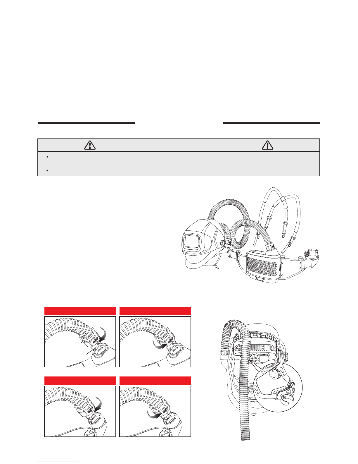
A complete Tecmen PAPR System includes a blower, filtration unit, breathing tube assembly,
battery, and a welding helmet with auto darkening filter.
The blower assembly draws surrounding air through its filter and supplies purified air to the
facial via a breathing tube. There are two levels airflow rate choice: Low speed—170+lpm;
High speed—210+lpm. Switch the airflow by short press Button. Warning lights allow you to
check the filter status. More warning lights turn on, more dirty it means. When warning lights
flash, please replace the filter.
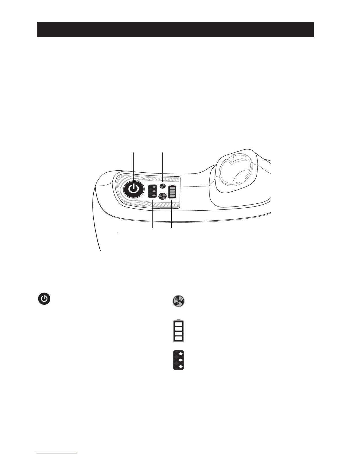
DESCRIPTION & SPECIFICATION
BUTTON
FILTER
WARNING
BATTERY
INDICATOR
AIRFLOW
Indicator light refers to the airflow state. Two
different levels: Low Speed—170+lpm, High
Speed—210+lpm
Warning lights help to check the filter status.
More light spots turn on,more dirty it means.
When warning lights flash, pls. replace the
filter.
Display screen indicates the battery capacity.
Only Button controlling both Power
On/Off and Airflow switch
1.Power On/Off
On—Press and hold for 3 seconds.
Off—Press and hold for few seconds until
bleeping sounds finish.
2.Airflow switch
Press the Button to switch between
170+lpm and 210+lpm
2
Page 4

RESPIRATOR SPECIFICATIONS
Manufacturer’s minimum design flow rate: 165+lpm (5.8+cfm)
Low speed: 170+lpm (6+cfm)
High speed: 210+lpm(7.4+cfm)
Battery type: Rechargeable Li-ion Battery
Battery duration: 9h-low speed(170+lpm); 5h-high speed(210+lpm)
Battery charge time: 3 hours
Battery life: 550 charges
Filter efficiency: 99.97%
Alarms: Visible, Audible and Vibrate
Operating temperature: 23°F to 131°F (-5°C to 55°C)
Storage temperature: 14°F to 131°F (-10°C to 55°C)
Operating R.H.: < 90%
Storage R.H.: < 85%
1027g (Blower Unit + Standard Battery)
EN12941 TH3 —— Highest level of respirator protection
Airflow Rate
Standard Battery
Filter
Temperature
Relative Humidity (R.H.)
Weight
Respirator Approval
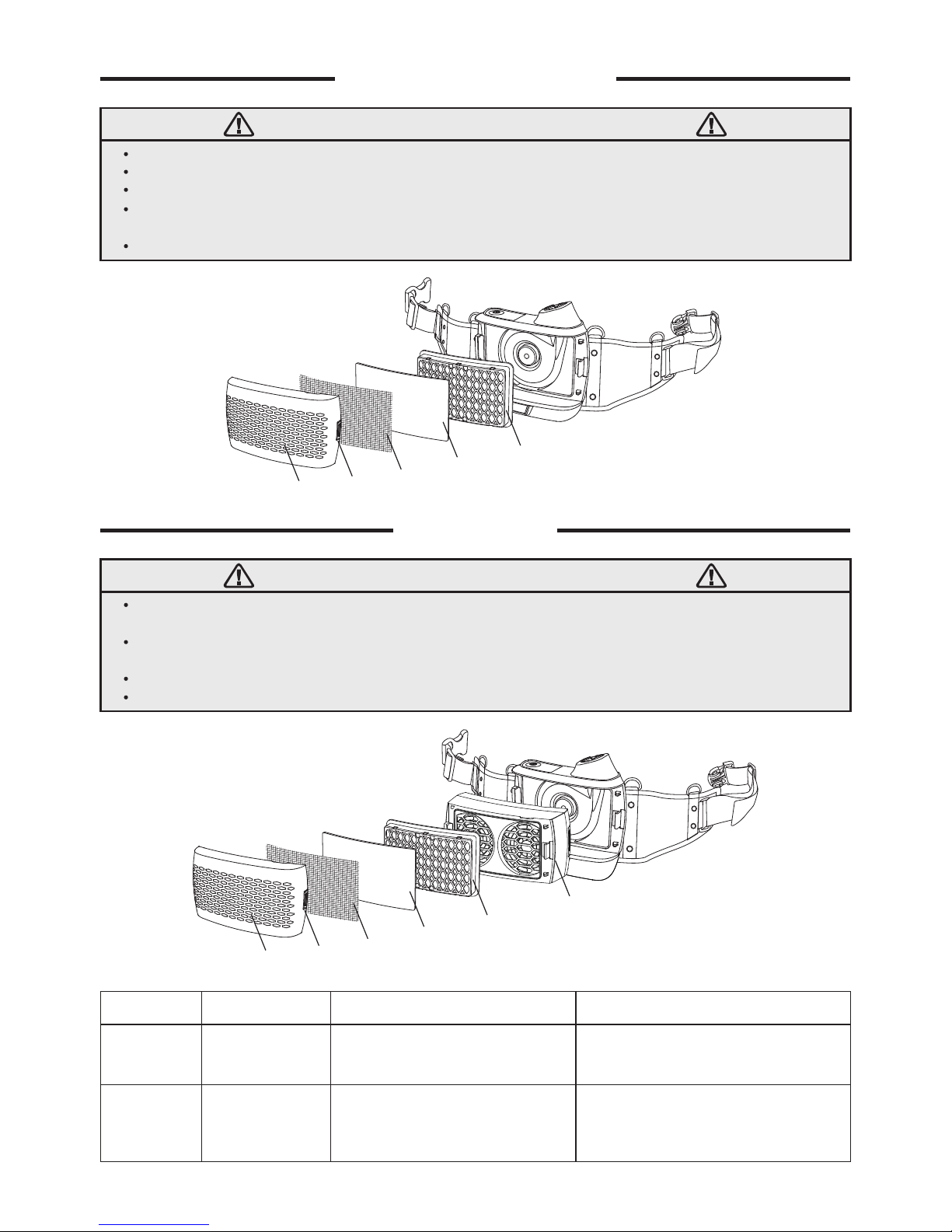
The power must be turned off when replacing the filters. Install the spark screen, pre-filter,
and particulate filter (gas filter if any) in filter cover.
Before installed, always make sure filter material is intact and dry with no tears or other
damages. Install the filter cover assembly to the blower unit by engaging tabs on filter cover
into bracket on blower unit and rotate assembly to close. Push filter cover assembly down
until latch clicks into position securing filter cover assembly. Inspect both sides of cover to
see that the filter cover is properly installed. To replace filter, push latch into release filter
cover and replace filter as fig.1 shown.
When to replace the filter: If the filter gets blocked by contaminants, all the three points of
warning lights will flash, accompanied with vibrate and bleeping sound. Please immediately
exit contaminated environment and check the status.
ASSEMBLING & SPARE PARTS
fig.1
3
Page 5
WARNING
PARTICULATE FILTER
Never use the respirator without the spark screen, pre-filter, and the HE particulate filter (HEPA) installed.
Always replace filter when damaged or blocked. Do not try to wash, clean or reuse dirty ones.
Stored at a temperature between 14°F to 131°F (-10°C to 55°C),in a clean environment without direct light.
Remember not confuse the markings on a filter relating to any standard other than EN 12941 with the classification
of this device when used with this filter.
Please install the particle filter according to fig.2a.
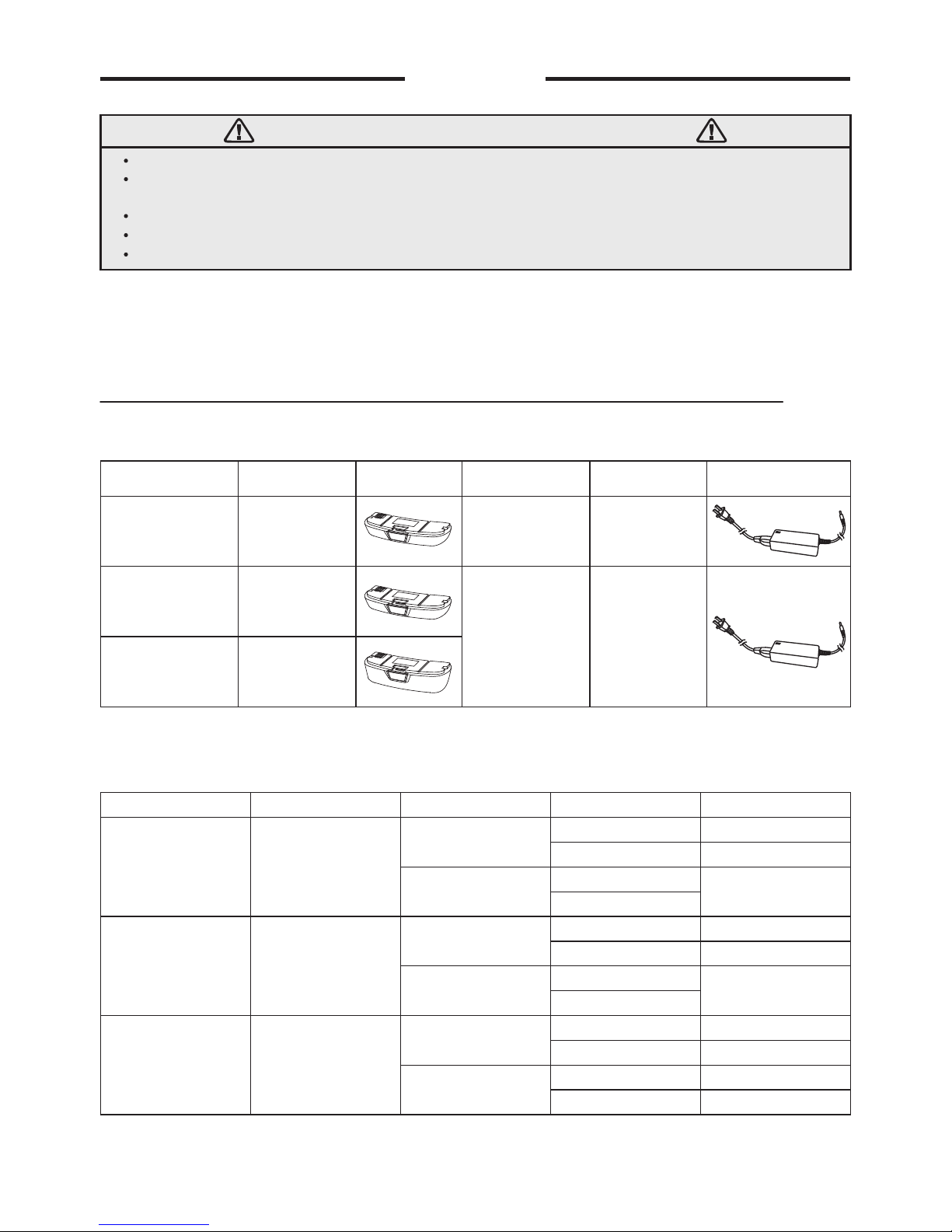
GAS FILTER
fig.2a
fig.2b
WARNING
This gas filter must be always used together with FreFlow particle filter. The gas filter give additional protection
against certain gaseous environment. (See the table below)
The particle filter and gas filter cannot be cleaned. Stop using it immediately when smelling peculiar smell and
replace it until you are in a safe area.
Stored at a temperature between 14°F to 131°F (-10°C to 55°C),in a clean environment without direct light.
Please install the particle filter and gas filter according to fig.2b.
Filter
Cover
Spark
Screen
Pre-Filter
Particulate
Filter
Latch
Filter
Cover
Spark
Screen
Pre-Filter
Particulate
Filter
Gas Filter
Latch
Marking Part No. Color Code Protection Against
P (R SL)
A1B1E1K1
V1P3 TM3 00
V1GF TM3 00
White
Brown / Grey / Yellow / Green
Particulates (R=replaceable,
SL=test against sodium chloride
and paraffin oil)
Organic gases / Inorganic gases /
Sulfur dioxide, acidic gases /
Ammonia and organic ammonia
derivatives
4
Page 6
BATTERY
WARNING
The battery should be charged in a place that is electrically safe.
The charging time of different types of battery is different. Actual charging time depends on the remaining
battery capacity.
Please check out the voltage of the charger (AC 110V~220V).
Please separate the battery from the body before charging.
Upon using-condition, the battery’s life may be slightly different.
Battery is divided into standard battery, fast-charging standard battery and fast-charging
extended battery. When these three types of battery are used with different filter
components, the battery duration is different. Please choose the appropriate battery
according to actual situation.
It is recommended to choose fast-charging extended battery to match the gas filter.
Standard Battery
Fast-charging
extended battery
Fast-charging
standard battery
Standard Battery
Fast-charging
extended battery
Fast-charging
standard battery
Battery charger
Fast-charging
battery charger
V1BA TM3 00
V1FBA TM3 00
V1FEB TM3 00
V1BC TM3 00
V1FBC TM3 00
Type Part No. Picture Picture Type Part No.
5
Battery type Filter type Airflow rate Battery duration
Particle
Particle + Gas
Particle
Particle + Gas
Particle
Particle + Gas
3 h
1 h
2 h
9 h
5 h
9 h
5 - 6 h
15 h
9 h
11 h
7.5 h
Battery performance for different combinations of filter assembly
Battery charge time
170+lpm
210+lpm
170+lpm
210+lpm
170+lpm
210+lpm
170+lpm
210+lpm
170+lpm
210+lpm
170+lpm
210+lpm
Not recommended
Not recommended
Page 7
Indicator Light
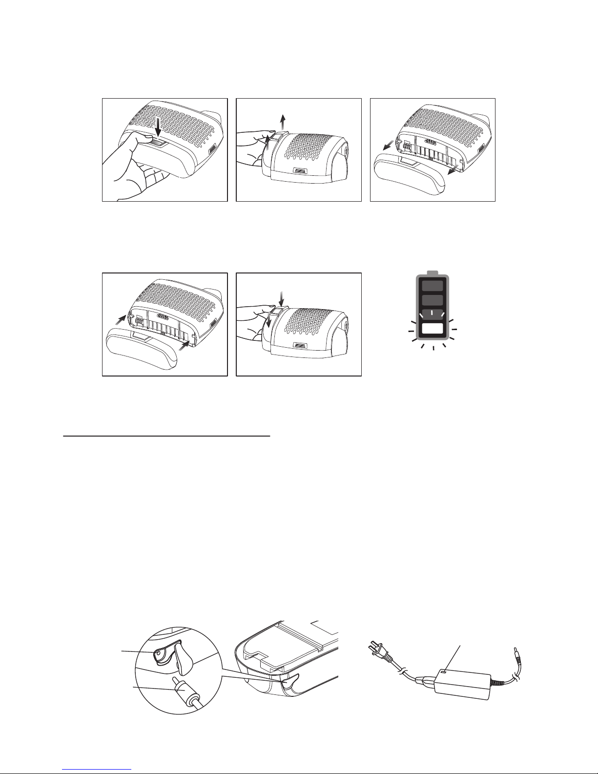
Disassembling the Battery
Push the button, take the battery out as fig.3a / 3b / 3c shown direction. Separate it from the
body.
fig.5a
Push
Pull
fig.3a fig.3b fig.3c
Push
Push
fig.4a fig.4b
Battery-charging
This indicator show the battery capacity.
When four sections show up, the battery is fully charged.
When just one section left (See fig.5a), bleeping sounds on, accompanied by vibration to
remind users to stop work and get battery charged. The frequency is bleeping sounds occur
every 30 seconds and vibration occurs every 2 minutes. After the warnings occur around 15
minutes, the battery indicator gets flashing, which shows there should be at most 15 minutes
left before the blower off (Airflow low speed 170+lpm).
Remove battery pack from blower assembly. Connect charger cord to battery terminal (See
fig.5b).
When the indicator light on charger turns from red to green (See fig.5c) , never stop it
immediately and please keep charging for another 0.5h.
Battery
Charging
Terminal
Charger
Cord
Battery
fig.5b fig.5c
Assembling the Battery
Fitting the battery to the blower body, push until hearing ‘Click’ sound. (see fig.4a / 4b)
6
Page 8
Notice of battery use
• Do not put PAPR unit with power-on in the package. It’s better to remove the battery from
the body when put in the package.
• Do not keep PAPR unit inside the car in hot summer season.
• Do not throw or give the high impact to PAPR unit.
• Do not put PAPR unit on the electric heat generating equipment.
• Do not use any other battery charger.
• Standard battery operation time:
9 hours at low speed (170+lpm), 5 hours at high speed (210+lpm).
• Battery storage temperature: 14°F to 115°F (-10°C - 45°C), R.H.< 85%
Breathing tube
O-ring
fig.7a fig.7b
fig.7dfig.7c
BREATHING TUBE
Assembling
Insert the two prongs on the breathing tube
into the blower unit and helmet air duct (See
fig.6), twist 1/4 to the anti- “open” direction
(See fig.7a / 7c), then clip the breathing tube
into holder on the back cover of the headgear
to lock into place (See fig.8).
Disassembling
Twist 1/4 to the “open” direction and then take
the prongs out from the blower unit and
helmet air duct (See fig.7b / 7d).
WARNING
Always inspect the PAPR end of the breathing tube to confirm the rubber O-ring is in place, see fig.7a. Replace if
missing or damaged.
Be sure tube is properly installed and non-filtered air cannot enter the facial.
fig.6
fig.8
7
Assembling from blower Disassembling from blower
Assembling from helmet Disassembling from helmet
Page 9

1. Blower Assembly
Make sure the spark screen, pre-filter and particulate filter (gas filter if any) are properly
installed and securely latched.
2. Breathing Tube
Make sure tube is not damaged and connected locked to the blower unit and helmet.
3. Battery
Check connection to blower unit is secure and battery is fully charged.
4. Airflow rate test / Alarm sound check
It’s necessary to do both airflow rate test and alarm sound check before use. Testing
method refers to page 9.
5. Face seal
Inspect face seal for damage and replace if necessary. Make sure the air is supplied to
helmet.
ENTER AND EXIT CONTAMINATED AREA
Before using Respirator - Check the following items.
AIR FLOW CONTROL
SHOULDER STRAP & BELT CUSHION
Two indicator lights on display (See fig.10a). Low Speed-170+lpm; High Speed-210+lpm.
When turn on the PAPR, default setting is low speed airflow; Switch the airflow by short
press the Button (See fig.10b).
Hook
fig.9a fig.9b
Low Speed — 170+lpm
High Speed — 210+lpm
fig.10a fig.10b
Connect hooks to belt (See fig.9a).
Connect with the blower by screw locking (See fig.9b).
8
Page 10

After turning on the product, check the alarm sound warning function by blocking the air
outlet as fig.11 shown in the picture above. The warning signal on the panel should flash with
a sound and blower vibrate (approximately 15 to 30 seconds after the outlet is blocked). The
product is working correctly if the warning functions follow the process above.
(Please make sure the filter is equipped and the battery is fully charged before doing this
test.)
SELF CHECK BEFORE EACH TIME USE
ALL THE TESTS MUST ALWAYS BE DONE IN A SAFE ENVIRONMENT.
Alarm sound check
fig.11
BLOCK AIR FLOW
WITH HAND
Steps
• Take off helmet and disconnect tube from helmet.
• Turn off the blower by long press button.
• Release belt. Remove straps from shoulders and remove blower off of your lower back.
• IF some problem is shown in any part of the product, for example, the air supply is stopped
or its amount is decreased;
• IF it gets hard to breathe, feeling dizzy or headache, feeling the smell or taste of the
contaminants and its stimulus occurred;
• NEVER use in place with too high level of contamination. If you suspect the levels reach a
level which this respirator may no longer provide enough protection.
WARNING
Never remove the respirator in areas where the air is contaminated.
Always take off the PAPR after you step out of the workplace.
Respirator removal
Always exit the contaminated area immediately if any of the following
conditions occur:
9
Page 11

Airflow rate test
Take airflow test always before using this product.
Make sure all the components are fully assembled before testing.
Connect the end of hose to the bottom of airflow indicator and then start the Button. Keep
the Flow Indicator vertical.(see fig.12)
If the ball inside the pipe floating above the limited line in low speed mode, it proves normal
function.
If the ball cannot float up to limited line, please refer to Trouble-shooting Guide on page11.
MAINTENANCE
The respirator components must be cleaned, inspected and prepared for next use
after each use. Use soft cloth dipped in mild soap water for wiping. Be careful for the
water NOT to get inside the body.
CLEANING
The face seal can be used to facilitate cleaning after disassembling from the shell, but it must
be replaced if it is damaged.
Blower unit and battery pack: Clean the outer surfaces of the PAPR and battery pack
with a soft cloth dampened in a solution of water and mild, pH neutral detergent. Be
careful for the water NOT to get inside the body. Do not use solvents or abrasive
cleaners. Ensure the electrical contacts of the motor/blower and battery pack are dry
before assembling well.
Breathing tube: Wiping the exterior is insufficient. Clean the outer hose and connection
on the breathing tube with the soft cloth dipped in water and detergent solution.
Optional breathing tube covers can also be used to facilitate cleaning. Ensure the
breathing tube is completely dry before using or storing. They cannot be immersed in
liquids for cleaning and must be replaced if wet.
Filter: Open the filter cover and inspect all the filters and spark screens. The Particle,
gas and pre-filters cannot be cleaned. The spark screen can be cleaned using a clean,
soft cloth dipped in a solution of water and a mild pH neutral detergent. Completely dry
the spark screen with a clean cloth. Replace the pre-filter and Particle filter if
excessively dirty, wet or damaged. Do not attempt to remove contamination using a
compressed air line as this will automatically invalidate the warranty. If the spark screen
cannot be cleaned or is damaged, replace with a new spark screen.
1.
2.
3.
Limited Line
Keep Vertical
fig.12
10
Page 12

TROUBLE-SHOOTING GUIDE
Blower not ON
No airflow from blower
Problems Trouble-shootingCauses
Airflow test failed
Battery time is too short
even fully charged
Increased sound level
Warning indicator ON,
blower vibrate and alarm
sound bleeping
Feeling smell of incoming air
Long press ON button.
Charge the battery.
Check and reassemble the
battery.
Check and clear the
obstruction.
Check the tube status.
Replace new filter.
Replace new battery.
Fully charge battery.
Replace filter.
Replace a new charger.
Replace filter and pre-filter
as required.
Check if tube/anywhere gets
blocked before use.
Check if the package is
removed.
Check the filter status and
replace new one if needed.
Check how the tube
assemble as well as status.
Check and equip both filters.
Battery no power
Battery not installed properly
Tube blocked/air leakage
Dirty filter needs replacement
Battery faulty
Incorrect charging
Blocked filter
Damaged charger
Filter is getting clogged
Damaged Filter
Hose with leakage problem
Filter component not
complete
Tube gets blocked/air
leakage
Filter assembled without
removing the package
The hose may get blocked/
air leakage
STORAGE
The TECMEN Freflow PAPR system is not intrinsically safe. Keep away from flammable, or
explosive atmosphere. Storage should be in a clean, dry, cool place with filter.
Blower storage
Stored at a temperature between 14°F to 131°F (-10°C to 55°C),in a clean environment
without direct light.
Battery storage
To help maximize battery service life:
• Disconnect the charger after a full charge has been received.
• Battery should be removed from blower if long time storage.
• Store the battery at 14°F to 115°F (-10°C to 45°C), R.H. <85%, to get maximize battery
service life.
11
Page 13

WELDING HELMET OPERATING INSTRUCTION
WARNING
Auto-Darkening welding helmets are designed to protect the eye and face from sparks,
spatter and harmful radiation under normal welding conditions. This auto darkening filter will
automatically turn on when pick it up. The filter automatically changes from a light state to a
dark state when an arc is struck, and it returns to the light state when welding stops.
The Auto-Darkening welding helmet comes assembled. But before it can be used, it
must be adjusted to fit the user properly. Check battery surfaces and contacts and
clean it if necessary. Verify if the battery is in good condition and installed properly.
Set up for delay time, sensitivity and shade number for your application.
The helmet should be stored in dry, cool and dark area and remove the battery, when
not using it for a long time.
WARNING
The user must stop using the auto-darkening welding helmet immediately
if the above-mentioned problems cannot be corrected. Contact the dealer.
• Irregular Darkening Dimming
Headband has been set unevenly and there is an uneven distance from the eyes to the filter
lens. (Reset the headband to reduce the difference to the filter).
• Auto-Darkening filter does not darken or flickers
① Front cover lens is soiled or damaged (Change the cover lens).
② Sensors are soiled (Clean the sensors surface).
③ Welding current is too low (Adjust the sensitivity level to higher).
④ Check battery and verify they are in good condition and installed properly. Also, check
battery surfaces and contacts and clean if necessary.
• Slow response
Operating temperature is too low (Do not use at temperatures below -5°C or 23°F).
• Poor vision
① Front/inside cover lens and/or the filter is soiled (Change lens).
② There is insufficient ambient light.
③ Shade number is incorrectly set (Reset the shade number).
④ Check if removing the film on the front cover lens.
• Welding helmet slips
Headband is not properly adjusted (Readjust the headband).
COMMON PROBLEMS AND REMEDIES
12
Page 14

CARTRIDGE OPERATION
• BATTERY INSTALLATION
Slide the battery holder out of the auto darkening filter,
(remove the used battery when replacing battery), put
new CR2450 batteries inside the battery holder, and put
the battery holder back into the auto darkening filter.
Please make sure the anode and cathode of the battery
are installed correctly (See fig.13).
• POWER ON / OFF
This auto darkening filter will automatically turn on when
pick it up.
Sensitivity level setting 0 - 9: The welding helmet will be
automatically off after 15 minutes not being used.
Sensitivity level setting =10: The filter will be darkening all
the time to meet some specially welding application under
both WELD MODE and CUTTING MODE. With this
setting, the welding helmet will not automatically turn off after 15 minutes of not being used.
To save power, remember to set the sensitivity value between 0 - 9 and keep the filter
in dark place when not being used.
• DIGITAL SCREEN ACTIVATION
Press any of four button to activate the digital screen (See fig.14a). After 6 seconds, digital
screen will automatically turn to standby mode. Short press the button again will active the
screen once more and previous settings will remain.
• MODE CONTROL
Short Press “ON / MODE” button to select the mode appropriate for the work activity
(See fig.14a):
Weld Mode − used for most welding applications. Push “FUNC” button to adjust shade
number, sensitivity, and delay settings properly before welding. In this mode the lens turns to
dark immediately when you start welding.
Cutting Mode − used for cutting applications. Push “FUNC” button to adjust shade number,
sensitivity, and delay settings properly before cutting. In this mode the lens turns to dark
immediately when you start cutting.
Grind Mode − used for grinding applications. In this mode the lens shade is fixed shade No.
4. Can not adjust shade number, sensitivity, and delay settings.
• BATTERY INDICATOR
The symbol “ ” show the current state of the battery (See fig.14b). The volume of batteries
has four levels symbol to appear (See fig.14c). The symbol “ ” appears on the display
screen before 1−2 days of battery life remains, the CR2450 lithium batteries should be
replaced in time. The symbol of the Battery Indicator is not real-time, should be updated
after pressing “ON / MODE” button shortly.
Be sure Positive (+) side of
battery faces up.
fig.14a fig.14b fig.14c
fig.13
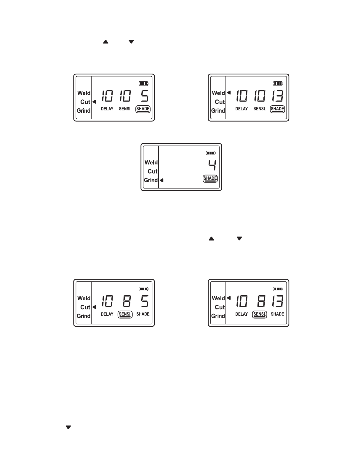
• VARIABLE SHADE CONTROL
After turn on the lens, short press “FUNC” button to choose “SHADE”, and adjust the lens
shade number. Use “ ” and “ ” buttons to select the lens shade in the dark state. The shade
range for each mode are as follows:
Cutting Mode − Shade 5 ~ 8 (See fig.15a) Weld Mode − Shade 9 ~ 13 (See fig.15b)
Grind Mode − No. 4 only (See fig.15c)
Select the proper shade number for your welding / cutting process, by referring to the “Shade
Guide Table” on page 19.
• SENSITIVITY CONTROL
Press “FUNC” button to choose “SENSITIVITY”. Use “ ” and “ ” buttons to make the lens
more or less sensitive to arc light of different welding processes. Sensitivity setting 5-10 is
the normal setting for everyday use. The sensitivity ranges for each mode are as follows:
Cutting Mode (Shade 5 ~ 8) / Weld Mode (Shade 9 ~ 13) − Sensitivity 0 ~ 10 (See fig.16a /
16b)
Grind Mode − No sensitivity adjustment
As a simple rule for optimum performance, it is recommended to set sensitivity to the
maximum at the beginning and then gradually reduce it, until the filter reacts only to the
welding light flash and without annoying spurious triggering due to ambient light conditions
(direct sun, intensive artificial light, neighbouring welder's arcs etc.).
It may be necessary to adjust helmet sensitivity to accommodate different lighting conditions
or if lens is flashing On and Off. Adjust helmet sensitivity as follows: Adjust helmet sensitivity
in lighting conditions helmet will be used in.
• Press “ ” button to lower setting to 0.
13
Page 15
• VARIABLE SHADE CONTROL
After turn on the lens, short press “FUNC” button to choose “SHADE”, and adjust the lens
shade number. Use “ ” and “ ” buttons to select the lens shade in the dark state. The shade
range for each mode are as follows:
Cutting Mode − Shade 5 ~ 8 (See fig.15a) Weld Mode − Shade 9 ~ 13 (See fig.15b)
Grind Mode − No. 4 only (See fig.15c)
Select the proper shade number for your welding / cutting process, by referring to the “Shade
Guide Table” on page 19.
• SENSITIVITY CONTROL
Press “FUNC” button to choose “SENSITIVITY”. Use “ ” and “ ” buttons to make the lens
more or less sensitive to arc light of different welding processes. Sensitivity setting 5-10 is
the normal setting for everyday use. The sensitivity ranges for each mode are as follows:
Cutting Mode (Shade 5 ~ 8) / Weld Mode (Shade 9 ~ 13) − Sensitivity 0 ~ 10 (See fig.16a /
16b)
Grind Mode − No sensitivity adjustment
As a simple rule for optimum performance, it is recommended to set sensitivity to the
maximum at the beginning and then gradually reduce it, until the filter reacts only to the
welding light flash and without annoying spurious triggering due to ambient light conditions
(direct sun, intensive artificial light, neighbouring welder's arcs etc.).
It may be necessary to adjust helmet sensitivity to accommodate different lighting conditions
or if lens is flashing On and Off. Adjust helmet sensitivity as follows: Adjust helmet sensitivity
in lighting conditions helmet will be used in.
• Press “ ” button to lower setting to 0.
fig.15bfig.15a
fig.15c
fig.16a fig.16b
14
Page 16

• Face the helmet in the direction of use, exposing it to the surrounding light conditions.
• Press “ ” button repeatedly until the lens darkens, then press “ ” button until lens clears.
Helmet is ready for use. Slight readjustment may be necessary for certain applications or if
lens is flashing on and off.
• DELAY CONTROL
Press “FUNC” button to choose “DELAY”, begin lens delay adjustments. Use the Lens Delay
Control “ ” and “ ” buttons to adjust the time for the lens to switch to the clear state after
welding or cutting.
Cutting Mode (Shade 5 ~ 8) / Weld Mode (Shade 9 ~ 13) − Delay 0 ~ 10 (See fig.17a / 17b)
Grind Mode − No sensitivity adjustment
The delay is particularly useful in eliminating bright after-rays present in higher amperage
applications where the molten puddle remains bright momentarily after welding. Use the
Lens Delay Control buttons to adjust delay from 0 to 10 (0.1 to 1.0 second). When welding
stopped, the viewing window automatically changes from dark back to light but with a
pre-set delay to compensate for any bright afterglow on the workpiece. The delay time /
response can be set from Level 0 to level 10. It is recommended to use a shorter delay
with spot welding applications and a longer delay with applications using higher currents.
Longer delays can also be used for low current TIG welding, and TIG / MIG / MAG pulse.
• ADJUSTING THE FIT OF THE HELMET
The overall circumference of the headband can be made larger or smaller by rotating the
knob on the back of the headband (See adjustment “Y” in fig.18). This can be done while
wearing the helmet and allows just the right tension to be set to keep the helmet firmly on
the head without it being too tight.
• If the headband is riding too high or too low on your head, adjust the strap which passes
over the top of your head. To do this release the end of the band by pushing the locking pin
out of the hole in the band. Slide the two portions of the band to a greater or lesser width
as required and push the locking pin through the nearest hole (See adjustment “W” in
fig.18).
• Front and back bands will automatically self-adjust according to headform, and soft pads
suit forehead and back of head perfectly, which will bring more comfort (See fig.19a). Test
the fit of the headband by lifting up and closing down the helmet a few times while wearing
it. If the headband moves while tilting, re-adjust it until it is stable.
• ADJUSTING THE DISTANCE BETWEEN THE HELMET AND THE FACE
Step 1: Press down and hold the “LOCK” latch on both sides (See fig.19b) and it can be
slide back and forth.
Step 2: Loosen the “LOCK” latch and keep it snap into slots. Please make sure the
distance between the lens to both eyes are equal, to avoid uneven darkness.
• ADJUSTING VIEW ANGLE POSITION
Tilt adjustment is located on right side of helmet. Loosen the right headgear tension knob
and adjust the lever forward or back to the proper position. Re-tighten the right headgear
tension knob (See fig.19c).
fig.17bfig.17a
15
Page 17

MAINTENANCE
• ADJUSTING VIEW ANGLE POSITION
Tilt adjustment is located on right side of helmet. Loosen the right headgear tension knob
and adjust the lever forward or back to the proper position. Re-tighten the right headgear
tension knob (See fig.19c).
fig.19b
fig.19a
fig.19c
‘W’
‘Y’
‘T’ ‘T’
TOP
fig.18
fig.20a fig.20b fig.20c
fig.21a fig.21b fig.21c
REPLACING THE SHELL COVER
Place fingertips into the gap around the shell cover and flex the shell cover upwards until it
releases from the helmet (See fig.20a / 20b). When installing the new shell cover, put the
side of lug boss of shell cover into the slot and then lock the other side into the helmet. When
hearing “click”,the shell cover is completely fixed (See fig.20c).
REPLACING THE AUTO DARKENING FILTER
Press the thumb on the bottom sides of the auto darkening filter and push it upward (See
fig.21a), remove the auto darkening filter from the shell (See fig.21b). When installing the
new auto darkening filter, clip the lower part of the filter into the bottom of helmet window first,
and then insert the whole filter into the helmet window (See fig.21c).
16
Page 18

fig.22a fig.22b
fig.23a fig.23b fig.23c
REPLACING THE OUTSIDE COVER LENS
Replace the outside cover lens if it is damaged. Place your fingernail in recess above filter
view window and flex lens upwards until it releases from edges of filter view window (See
fig.22a). When installing new outside cover lens, align one side of lens into the slot, and then
insert into the other side.
REPLACING THE INSIDE COVER LENS
Replace the inside cover lens if it is damaged. Place your fingernail in recess above filter
view window and flex lens upwards until it releases from edges of filter view window (See
fig.22b).
REPLACING THE GRINDING LENS AND GRINDING LENS COVER
Place fingertips into the gap around the grinding lens cover (See fig.23a), and flex the cover
upwards until it releases from helmet (See fig.23b). Press the grinding lens lightly and push
inward, remove the lens from slot and take it out carefully (See fig.23c). When installing new
grinding lens, put one side of lens into slot, and then insert into the other side. When
installing new grinding lens cover, put the side of lug boss of lens cover into the slot and then
lock the other side into the helmet. When hearing “click”, the lens cover is completely fixed.
REPLACING THE FACE SEAL
Press the “LOCK” key on cantilevered components and push the headgear in the direction
of arrow to separate headgear from the helmet (See fig.24a). In accordance with the order
of 1-4 in the figure, aligh the face seal with the velcro inside the helmet shell and make sure
the face seal is closely attached to helmet shell (See fig.24b). Then press the “LOCK” key on
cantilevered components to install the headgear to the helmet (See fig.24c), buckle up the
face seal according to 1-5 points (See fig.24d).
17
Page 19

fig.24a fig.24b
fig.24c
fig.24d
CLEANING
Clean helmet by wiping with a soft cloth. Clean the filter surfaces regularly. Do not use strong
cleaning solutions. Clean sensors and solar cells with methylated spirit and a clean cloth and
wipe dry with a lint-free cloth.
18
Page 20

SHADE GUIDE TABLE
(1)
As a rule of thumb, start with a shade that is too dark, then go to a lighter shade which gives sufficient view of the weld zone without going below
the minimum. In oxyfuel gas welding or cutting where the torch produces a high yellow light, it is desirable to use a filter lens that absorbs the yellow
or sodium line the visible light of the (spectrum) operation
(2)
These values apply where the actual arc is clearly seen. Experience has shown that lighter filters may be used when the arc is hidden by the workp
iece.
Data from ANSI Z49.1-2005
Shielded metal arc
welding
Gas metal arc
welding and flux
cored arc welding
Gas tungsten arc
welding
Air carbon
Arc cutting
Plasma arc welding
Plasma arc cutting
Torch brazing
Torch soldering
Carbon arc welding
Gas welding
Light
Medium
Heavy
Oxygen cutting
Light
Medium
Heavy
Less than 3 (2.5)
3-5 (2.5–4)
5-8 (4–6.4)
More than 8 (6.4)
(Light)
(Heavy)
(Light)
(2)
(Medium)
(2)
(Heavy)
(2)
Under 1/8
1/8 to 1/2
Over 1/2
Under 1
1 to 6
Over 6
Less than 60
60-160
160-250
250-550
Less than 60
60-160
160-250
250-500
Less than 50
50-150
150-500
Less than 500
500-1000
Less than 20
20-100
100-400
400-800
Less than 300
300-400
400-800
–
–
–
Under 3.2
3.2 to 12.7
Over 12.7
Under 25
25 to 150
Over 150
—
10
12
14
—
11
12
14
10
12
14
12
14
6 to 8
10
12
14
8
12
14
3 to 4
2
14
4 or 5
5 or 6
6 or 8
3 or 4
4 or 5
5 or 6
7
8
10
11
7
10
10
10
8
8
10
10
11
6
8
10
11
8
9
10
–
–
–
GUIDE FOR SHADE NUMBERS
OPERATION ELECTRODE SIZE ARC MINIMUM SUGGESTED
(1)
1/32 in. (mm) CURRENT (A) PROTECTIVE SHADE NO.
SHADE (COMFORT)
PLATE THICKNESS
in. mm
19
Page 21

TECHNICAL SPECIFICATIONS
Optical Class:
Viewing Area:
Cartridge Size:
Arc Sensor:
Light State:
Grind State:
Cutting Shade:
Welding Shade:
Shade Control:
Power On / Off:
Sensitivity Control:
UV / IR Protection:
Power Supply:
Switching Time:
Grinding:
Delay (Dark to Light):
Low Amperage TIG Rated:
Operating Temp.:
Storing Temp.:
Helmet Material:
ADF Weight:
Application Range:
Approved:
1 / 1 / 1 / 1
107 x 75 mm (4.21" x 2.95")
156 x 123 x 33 mm (6.14" x 4.84" x 1.30")
4
DIN 3.5
DIN 4
Shade No. from 5 to 8
Shade No. from 9 to 13
Internal, Digital Display Control
Automatic On / Off
Low ~ High, Digital Display Control
Up to Shade DIN16 at all times
Solar cell. Battery replaceable,
2 × CR2450 lithium battery
1/25,000 s. from Light to Dark
Yes
0.1 ~ 1.0 s, Digital Display Control
≥ 2 amps (DC); ≥ 2 amps (AC)
-10 °C ~ +55 °C (14 °F ~ 131 °F)
-20 °C ~ +70 °C (- 4 °F ~ 158 °F)
High Impact Resistance Nylon
160 g
Stick Welding (SMAW); TIG DC&AC; TIG Pulse DC;
TIG Pulse AC; MIG/MAG/CO2; MIG/MAG Pulse;
Plasma Arc Cutting (PAC); Plasma Arc Welding (PAW);
Air Carbon Arc Cutting (CAC-A); Oxyfuel Gas Welding
(OFW); Oxygen Cutting (OC); Grinding
DINplus, CE, ANSI Z87.1, CSA Z94.3, AS/NZS 1338.1
20
Page 22

PART LIST
1
1
1
2
3
5
6
7
8
9
10
11
12
4
2
2
2
3
1
2
3
4
5
6
7
9
8
21
The part with * means it is not included in the product, which need to be
purchased seperately.
Page 23

PART LIST
22
Shell cover
Outside cover lens
Auto darkening filter
Inside cover lens
Grinding lens cover
Grinding lens
Helmet shell
Side window
Side window cover
Face seal
Air duct
Headgear (Including Sweatband)
Body
Standard battery
Particle filter (P3 Filter)
Pre-filter
Spark screen
Filter cover
Gas filter
Fast-charging standard battery
Fast-charging extended battery
Shoulder strap
Belt cushion (Include Screws & Washers)
Hose cover
O-ring
Hose
Standard battery charger
Fast-charging battery charger
Airflow indicator
V3SC TM26 00
FC TM26 00
ADF950S IEXP
IC TM950S 00
V3LC TM26 00
V3GL TM26 00
V3PH TM26 00
V3SW TM26 00
V3SWC TM26 00
V3FS TM26 00
V3AD TM26 00
V3HG TM26 00
V1BM TM3 00
V1BA TM3 00
V1P3 TM3 00
V1PF TM3 00
V1SS TM3 00
V1FC TM3 03
V1GF TM3 00
V1FBA TM3 00
V1FEB TM3 00
V1SH TM3 00
V1BE TM3 00
V1HC TM3 00
V1OR TM3 00
V1HO TM3 00
V1BC TM3 00
V1FBC TM3 00
V1AI TM3 00
A.Tecmen PAPR Helmet Assembly
A-1
A-2
A-3
A-4
A-5
A-6
A-7
A-8
A-9
A-10
A-11
A-12
B. Blower Unit
B-1
B-2
B-3
B-4
B-5
B-6
B-7*
B-8*
B-9*
C. Wears
C-1
C-2
D. Hose
D-1
D-2
D-3
E.Battery Charger
E-1
E-2*
F.Airflow Indicator
F
ITEM PART NO. DESCRIPTION
The part with * means it is not included in the product, which need to be
purchased seperately.
Page 24

Tecmen’s only obligation shall be repair, replace or refund the purchase price of such parts
or products material and fabrication defects free of charge within the warranty period.
This warranty does not cover to cause by improper handling abuse or application other than
recommended in the user instruction.
If you come across any problem during warranty period, contact your distributor, send the
defective parts together with the completed defect problem if necessary.
Thank you very much for choosing a TECMEN product!
For future reference, please complete the owner’s record below:
Serial Number:
Purchase Date:
WARRANTY
R
 Loading...