


Graph ventilator
Technical manual
(review 04)
MAY 2006

CONTENT
CHAPTER I
GENERAL AND OPERATION FEATURES
TECHNICAL DATA AND SPECIFICATIONS
CONTROL PANEL
SAFETY MECHANISMS
CHAPTER II
MAINTENANCE INSTRUCTIONS
CHAPTER III
TROUBLE SHOOTING
CHAPTER IV
SENSOR VERIFICATION
CHAPTER V
EQUIPMENT OPENING AND CLOSURE
CHAPTER VI
DETAIL OF ASSEMBLIES
CHAPTER VII
ELECTRONIC BOARDS: DETAIL
CHAPTER VIII
CALIBRATION
CHAPTER IX
FINAL CONTROL

CHAPTER I
GENERAL AND OPERATION
FEATURES

TECHNICAL AND MAINTENANCE MANUAL
Graph VENTILATOR
Review : 04
Date:
09/05/06
1
Characteristics and Principles of Operation
Generic definition
It is a device for continuous use foreseen to control mechanically or to help the
patient’s ventilation, giving a predetermined oxygen concentration in the breathing gas
with an adjustable volume or pressure.
Intended use
Purpose and function of the NEUMOVENT Graph Ventilator:
§ Lung ventilator for mechanical ventilation of medical application, electric and
pneumatically driven and microprocessor-controlled.
§ The intended use is to provide continuous ventilation to patients requiring
ventilatory support. This product is intended to be used in a wide range of
patient from infants until adults and to cover a variety of clinical conditions, and
to be used in short or long terms.
§ The device is intended for used in hospitals and hospital-type facilities that
provide respiratory care for patients requiring respiratory support.
Classification
Class: llb (Rule 9). Active therapeutic devices intended to administer or exchange
energy to or from the human body in a potentially hazardous way.
Type: Active medical Device.
Operative Mode: Continuous.
Life Cycle: 5 years if maintenance schedule is followed.
WARNING: Do not use the ventilator in the presence of flammable anesthetics.
An explosion or fire may result.
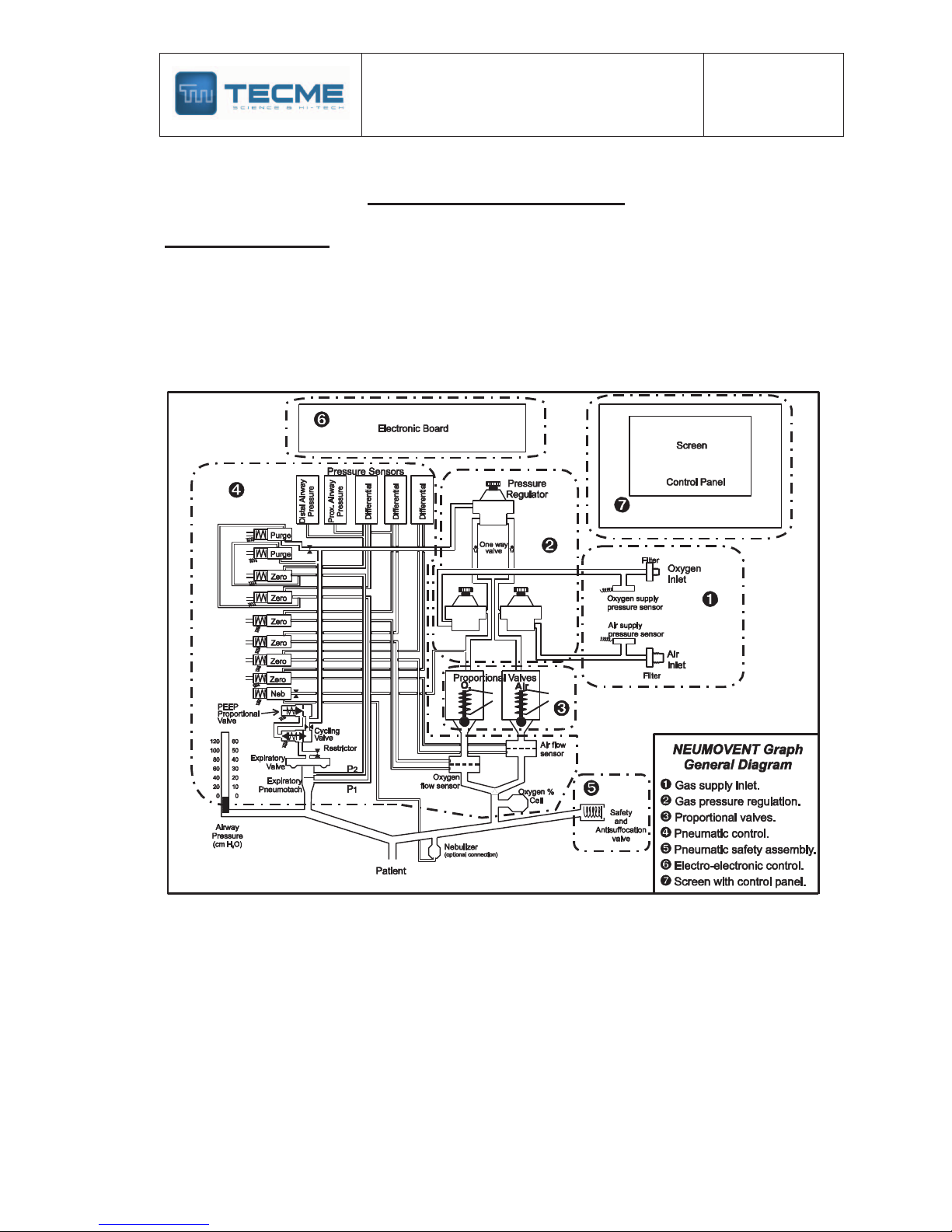
Description
The NEUMOVENT Graph Ventilator comprises a system of related elements and
designated to alter, transmit and apply energy directly, and in a predetermined mode,
replacing or contributing with the patient's muscular capacity in the execution of the
work of breathing with the intention of achieving an efficient gas exchange.
This function of increase the mechanical support to the patient can be explained for
the following:
1. Control Mechanism. It explains how the machine can work to increase or
supplement the patient's breathing effort.
2. Control Circuit. It defines what types of devices are used to complete this task.
3. Control Variables. It defines which are the dynamic elements that control any
stage in the course of the breathing cycle.
4. Breathing Phases Variables. It explains how the ventilator responds to changes
that produce the beginning, the support and the end of the breathing cycle.
1. Control Mechanism
To understand how the machine can control the substitution or the supplementation
of the natural function of breathing, before, it is required to explain something on the
mechanics of breathing. Specifically on the pressure that is necessary to exercise to
make a flow enters to the airway and increase the volume of the lungs.
TECHNICAL AND MAINTENANCE MANUAL
Graph VENTILATOR
Review : 04
Date:
09/05/06
2
In the course of an inspiration and expiration, there is a change of pressure, volume
and flow. A mathematical model called Equation of the Motion of the breathing
system describes this change.
Equation of Motion
Muscle Pressure + Ventilator Pressure = Volume
+ Resistance x Flow
Compliance
Muscle pressure: Forces generated by the breathing muscles during the inspiration.
Ventilator Pressure: Transrespiratory Pressure generated by the ventilator during the
inspiration (e.g.: pressure of the airway less pressure of the surface of the body).
The combined muscle and ventilator pressure cause volume and flow to be delivered to the
patient. Pressure, volume and flow change with time and hence are variables. The
compliance and the resistance are the constants maintained by the respiratory system.
If the patient’s ventilatory muscles are not functioning, the ventilator must generate all the
pressure required to deliver the tidal volume and the inspiratory flow rate. In this case, it will
control the ventilation.
The NEUMOVENT Graph Ventilator is able to control the pressure waveforms like the flow
waveforms. This control also can be doing in a single inspiration.
2. Control Circuit
The NEUMOVENT Graph Ventilator uses an electronic circuit to perform, control and monitor
the ventilation. The critical components of this system include a microprocessor, pressure
sensors and servo proportional valves.
3. Control Variables
As it was mentioned, the control variables of the NEUMOVENT Graph Ventilator are the
Pressure and the Flow.
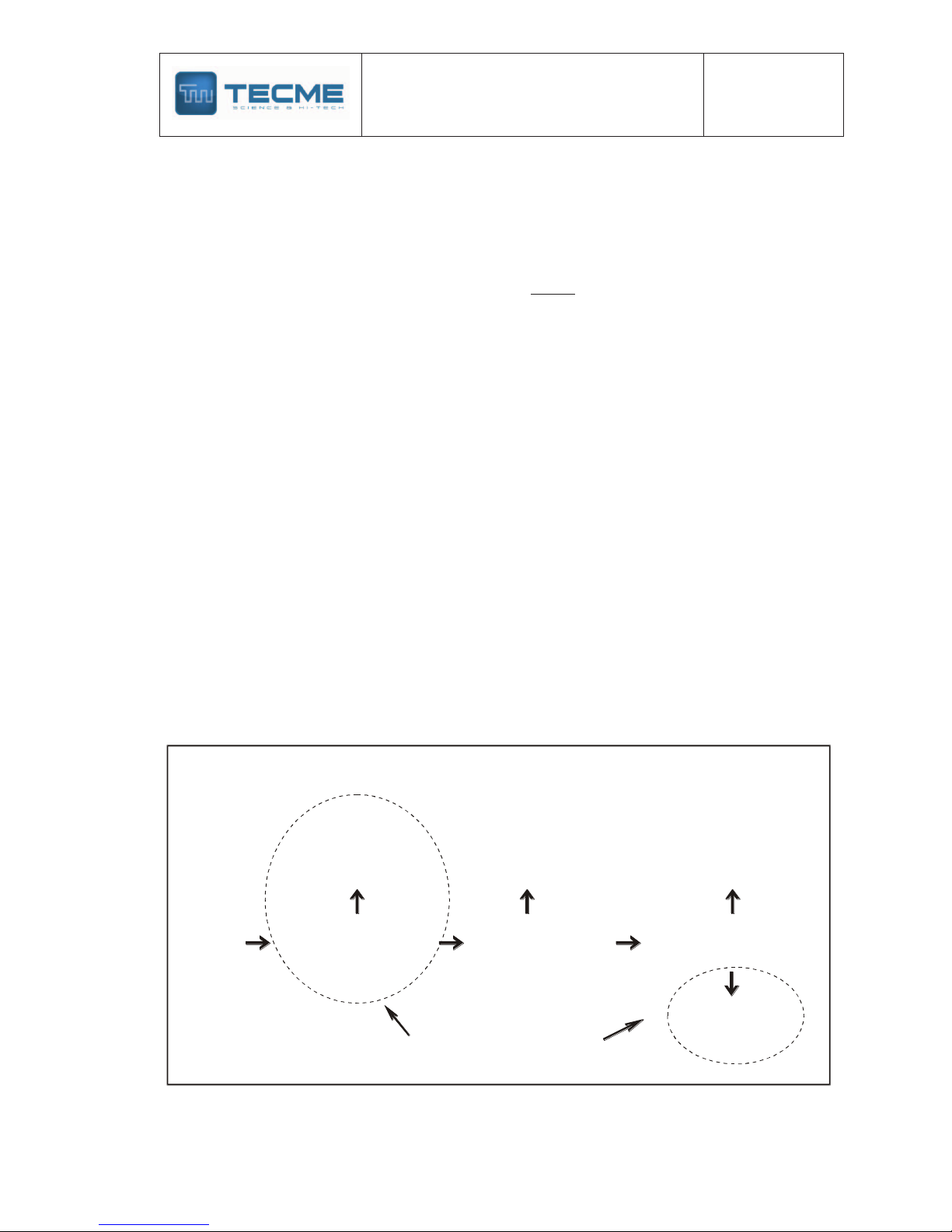
The equation of motion establishes that if the Pressure is selected as the control variable,
then the ventilator is a pressure controller. Therefore, the left side of the equation will be
Criteria for determining the control variable
The ventilator is a
Time
Controller
NEUMOVENT Graph
The ventilator is a
Volume
Controller
The ventilator is a
Fow
Controller
Observation
and
previous
knowledge
The ventilator is a
Pressure
Controller
Does pressure waveform
change when patient
resistance and compliance
change?
Does volume waveform
change when patient
resistance and compliance
change?
Is volume measured directly
(by volumetric displacement
rather than by flow
transducer)?
no yes yes
yes
no
no
(modify from. Chatburn )
(9)

TECHNICAL AND MAINTENANCE MANUAL
Graph VENTILATOR
Review : 04
Date:
09/05/06
3
determined by the selections made in the ventilator and they won't be affected by the
changes of the right side (compliance and resistance). As it will be seen, the Pressure
Controlled (PCV) and Pressure Support (PSV) modes use the pressure as the control
variable.
If the change of volume (VT) is maintained stable when the compliance or the resistance
change and simultaneously the flow are measured directly (pneumotachograph), then the
ventilator is classified as a flow controller.
The Volume mode of the NEUMOVENT Graph Ventilator uses the flow as the control
variable. The Pressure Support mode with Volume Assured is able to change, in oneself
inspiratory phase, from pressure controller to flow controller.
4. Breathing phases variables
In each one of the ventilation phases (inspiration and expiration), a particular variable is
measured and used to begin, sustain and conclude the phase. In this context, pressure,
volume, flow and time are referred as the phase variables.
TECHNICAL AND MAINTENANCE MANUAL
Graph VENTILATOR
Review : 04
Date:
09/05/06
4
Principles of Operation
Operative definition
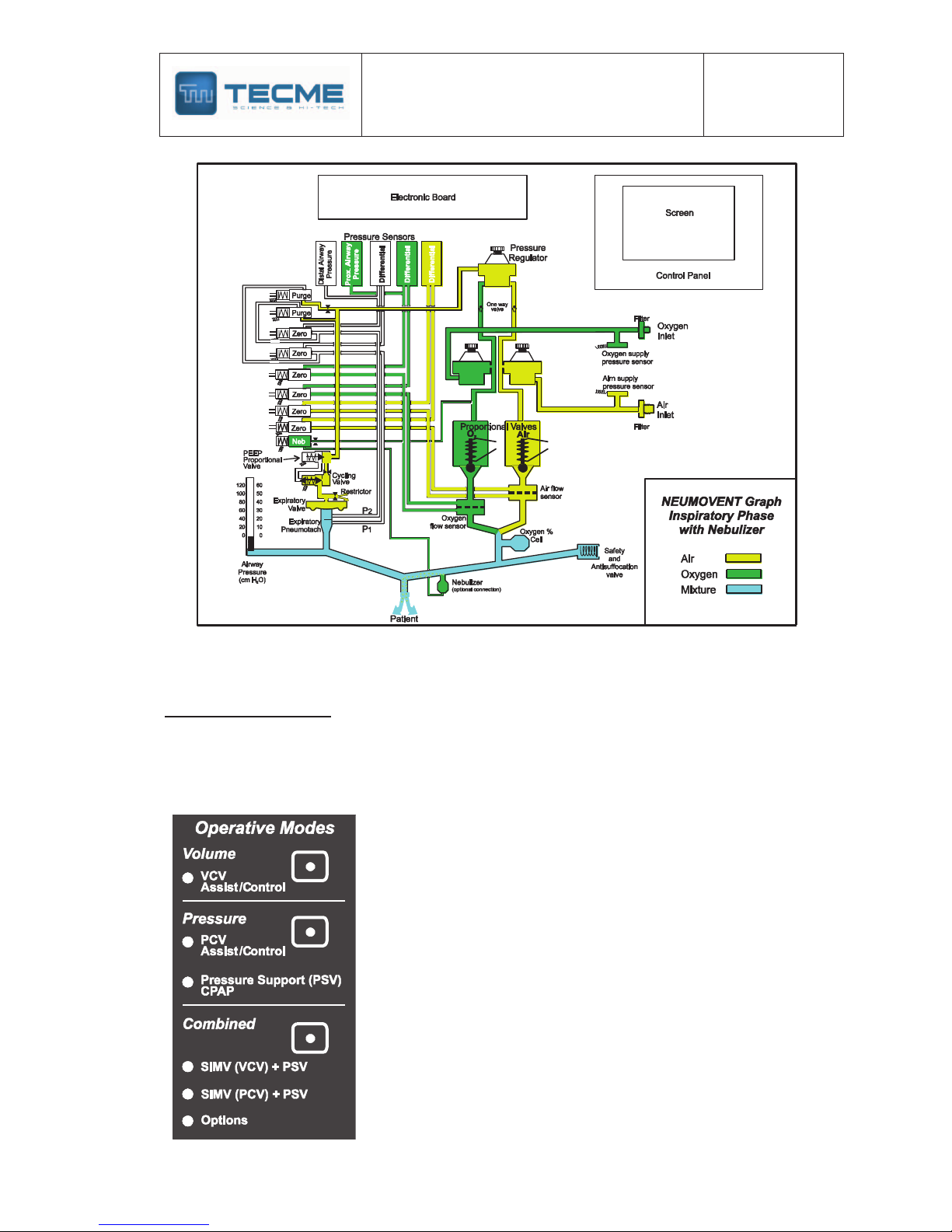
The NEUMOVENT Graph Ventilator is a pressure or flow controller. The inspiration is
triggered by pressure, flow, time or manually. It is pressure, volume or flow limited and
pressure, volume, flow or time cycled.
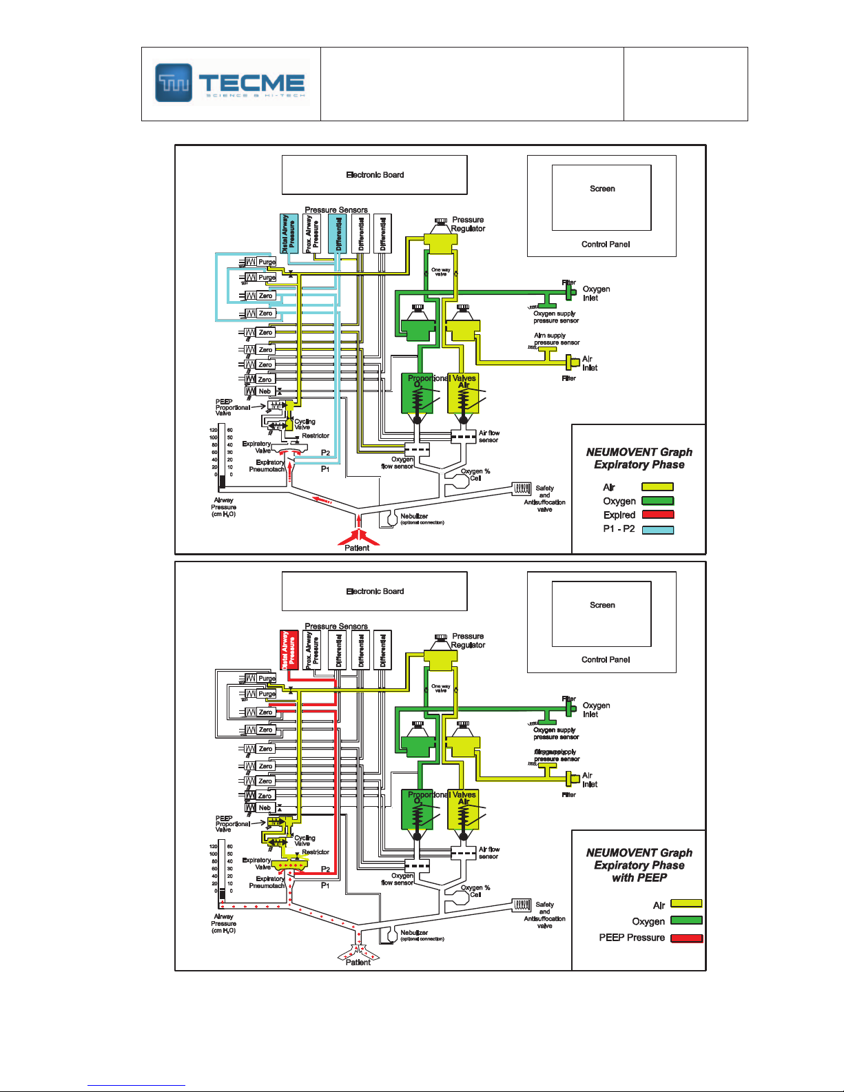
Two proportional valves, one for air and another for oxygen regulate the flow of gas to the
patient. The valves work simultaneously during each respiratory phase mixing the gases to
get the set FIO2.
The microprocessor receives the airway pressure and the inspiratory flow signals, and it
controls the orders for the adjusted variables and the output signals. The airway pressure
sensor is connected at the beginning of the patient's circuit. This sensor also manages the
feedback signals that are used for pressure triggering, alarms levels, and to control the
pressure waves in the pressure controlled, pressure support and mandatory minute
ventilation modes. Two differential pressure transducers related with the internal and external
pneumotachographs obtain the information of the delivered and exhaled flow. The two output
pneumotachographs are screen type; the expiratory is of variable orifice. Also, the signals of
the first are used to control the flow waveform and the tidal volume regulated as reference.
TECHNICAL AND MAINTENANCE MANUAL
Graph VENTILATOR
Review : 04
Date:
09/05/06
5
Control valves
The mentioned proportional valves regulate the gas flow to the patient. The flow control is
able to send flows up to 180 L/min when the gases are from a central-supply system, and of
120 L/min when a portable compressor provides the air.
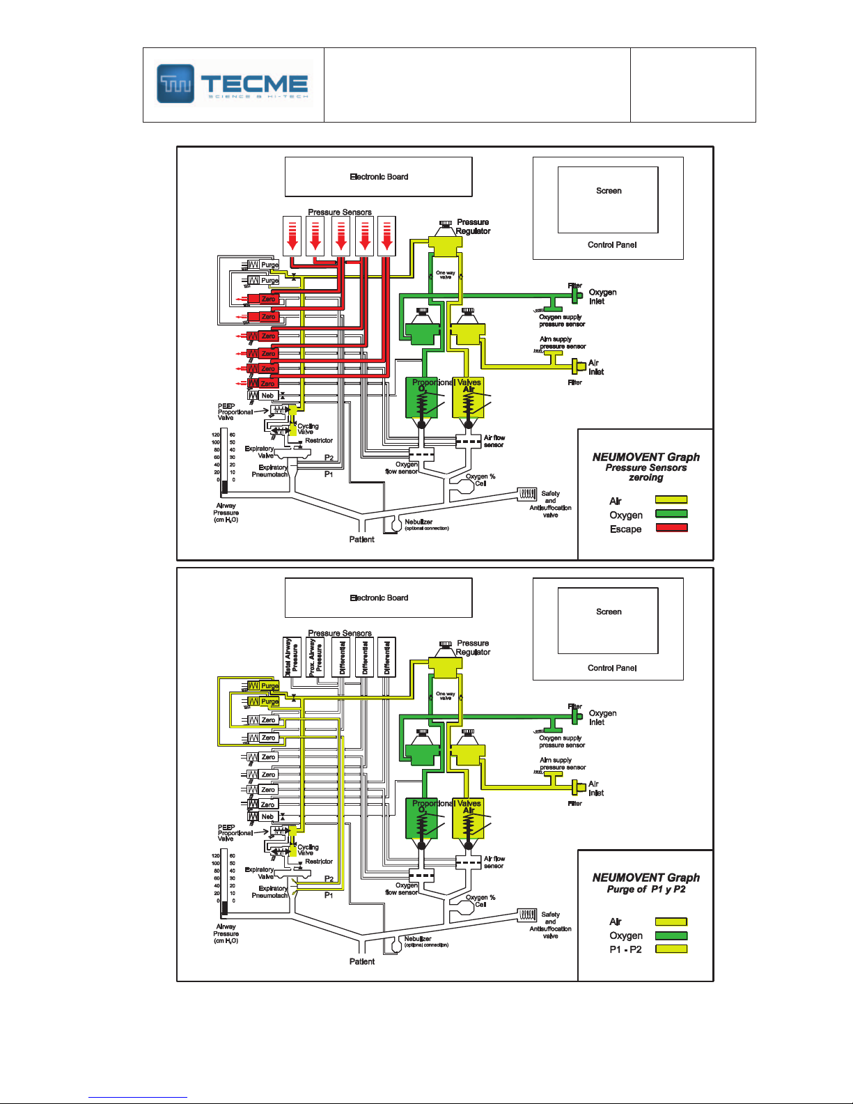
Two solenoids valves govern the expiratory valve, one for the closing and opening
(beginning and end of the inspiratory phase). The other one is a low flow proportional valve
that regulates the partial closing of the expiratory valve to produce positive pressure at the
end of the expiration (PEEP). The activity of these valves is coordinated by the
microprocessor, synchronizing its actions.
The system of valves has, also, four solenoids valves that act synchronously every 15
minutes to make a system zeroing (atmospheric pressure) of all sensors. At the same time,
another solenoid valve allows to pass a calibrated compressed air flow to purge the lines of
the expiratory pneumotachograph to avoid the entrance of water and humidity to the sensors.
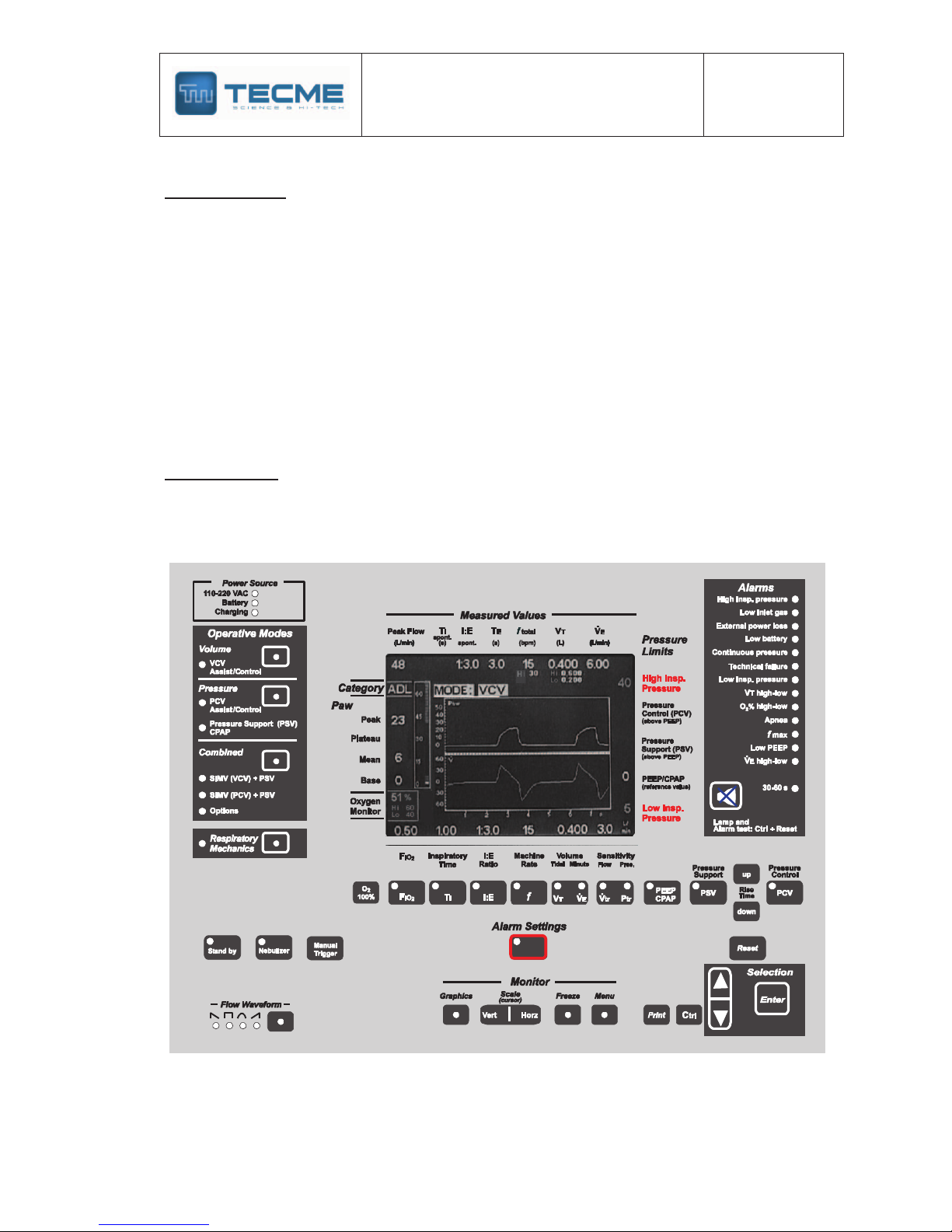
Control panel
The control panel comprises the keys to select the different modes and functions. In the
center there is a LCD screen where the results appear, so much in numeric data as graphic
representations and messages.
Some keys have lamps to indicate activation of the required function. The graphics in real
time of pressure, flow, volume, pressure/volume and flow/volume loops appear in successive
TECHNICAL AND MAINTENANCE MANUAL
Graph VENTILATOR
Review : 04
Date:
09/05/06
6
form pressing a key. The airway pressure is represented dynamically by an analogical bar
graph.
The numeric values exhibited below and to the right of the screen are those programmed by
the operator. Those of the superior and left part are resulting values.
Some values have small characters, as the indication of high and low alarm limit of VT.
Others are remarkable as the high and low-pressure limit.
The mode in use is shown with highlighted video inverse characters. Above the mode in use
appears, when it is programmed, the sigh and/or pauses indication.
Likewise, the screen shows messages indicating an alarm state or to execute some action.
Respiratory cycle
The process of insulation of gas to the lungs by means of the mechanic ventilation with the
NEUMOVENT Graph Ventilator comprises four steps:
1) Start of inspiratory phase
2) Progression of inspiration
3) End of inspiration
4) Expiratory phase
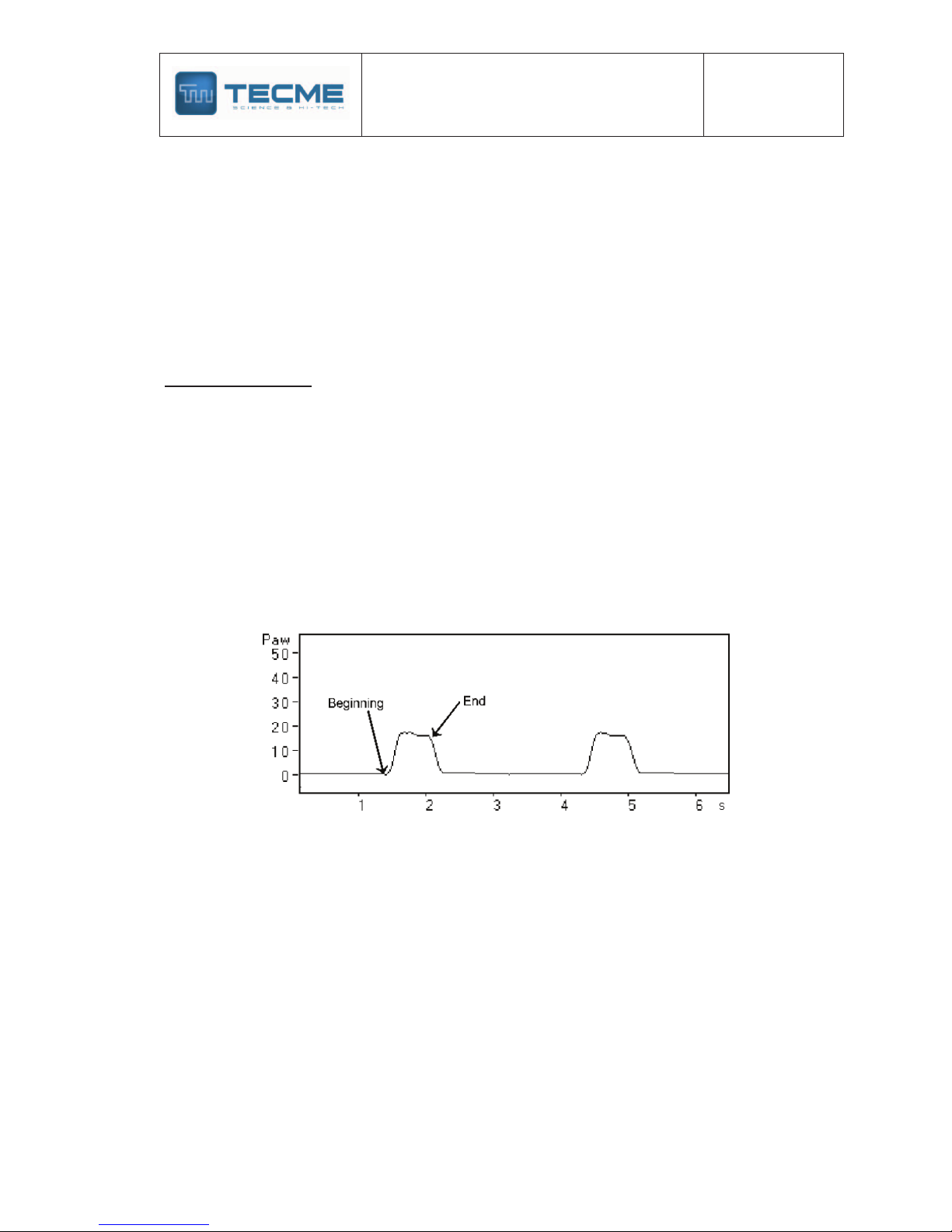
Start of inspiratory phase
The beginning of the inspiration can be automatic (for action of the respiratory frequency
control) or for the patient's initial inspiratory effort. In the first case the ventilation will be of
controlled type and in second assisted type.
Pressure breathing curves where is pointed out the beginning and the end of
the inspiratory phase.
For selection of assist/control ventilation the Volume (VCV) or Pressure (PCV) modes are
used. The spontaneous ventilation includes, in this ventilator, the Pressure Support (PSV)
mode and its combinations, where the patient begins and ends the inspiration according to
he/she demand.
The inspiratory effort that triggers the inspiratory phase modifies the pressure of the
breathing circuit or it produces variation of a continuous flow in the same circuit. In both
cases the system is regulated by means of the Inspiratory Sensitivity control.
From the mechanical point of view, the closing of the expiratory valve and the opening of the
flow of gas mixture toward the breathing circuit and the patient characterize this stage.
Progression of inspiration
The duration of this stage depends on the time during which comes out flow of the ventilator
toward the breathing circuit and the patient, while the expiratory valve remains closed.
TECHNICAL AND MAINTENANCE MANUAL
Graph VENTILATOR
Review : 04
Date:
09/05/06
7
The form in the flow administration depends on the ventilatory mode and of the selected flow
waveform.
In the VCV mode the flow waveforms, which can be selected, are: descending ramp (decelerating),
rectangular (continuous flow), sinusoidal, ascending ramp (accelerating). In the pressure modes
(PCV and PSV) the flow waveform is decelerating, except in PSV with volume assured where it
could be combined decelerating with continuous flow in the same inspiratory phase.
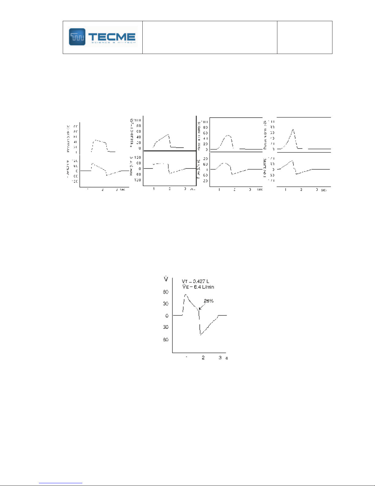
Layouts of pressure (up) and flow (below) curves. From left to right: Flow in
descending ramp, rectangular, sinusoidal, ascending ramp. Notice the
modifications of the curves of pressure according to the used flow.
End of inspiration
The suspension of the ventilator inspiratory flow depends on the time selected in the VCV
and PCV modes.
In the PSV mode depends on the fall of the inspired flow until a derivative percentage of the
initial flow of that same inspiration is reached. The regulation of this Expiratory Sensitivity can
be made from 5% up to 40% of the initial flow. The default percentage is 25%.
Flow curve during Pressure Support (PSV). In this case the inspiration finishes
when the flow has diminished to 25% of the initial flow (default value).
Expiratory phase
It begins when the expiratory valve opens up allowing escaping the flow exhaled by the
patient. This action is passive and it carries out by the elastic recoil of the lung and the
thoracic cage. Generally, the expiratory flow waveform shows an inverted peak which returns
with variable retard to the zero flow line. The delay in reaching the zero can be due to
expiratory retard of an obstructive lung disease or for breathing circuit defects.
TECHNICAL AND MAINTENANCE MANUAL
Graph VENTILATOR
Review : 04
Date:
09/05/06
8
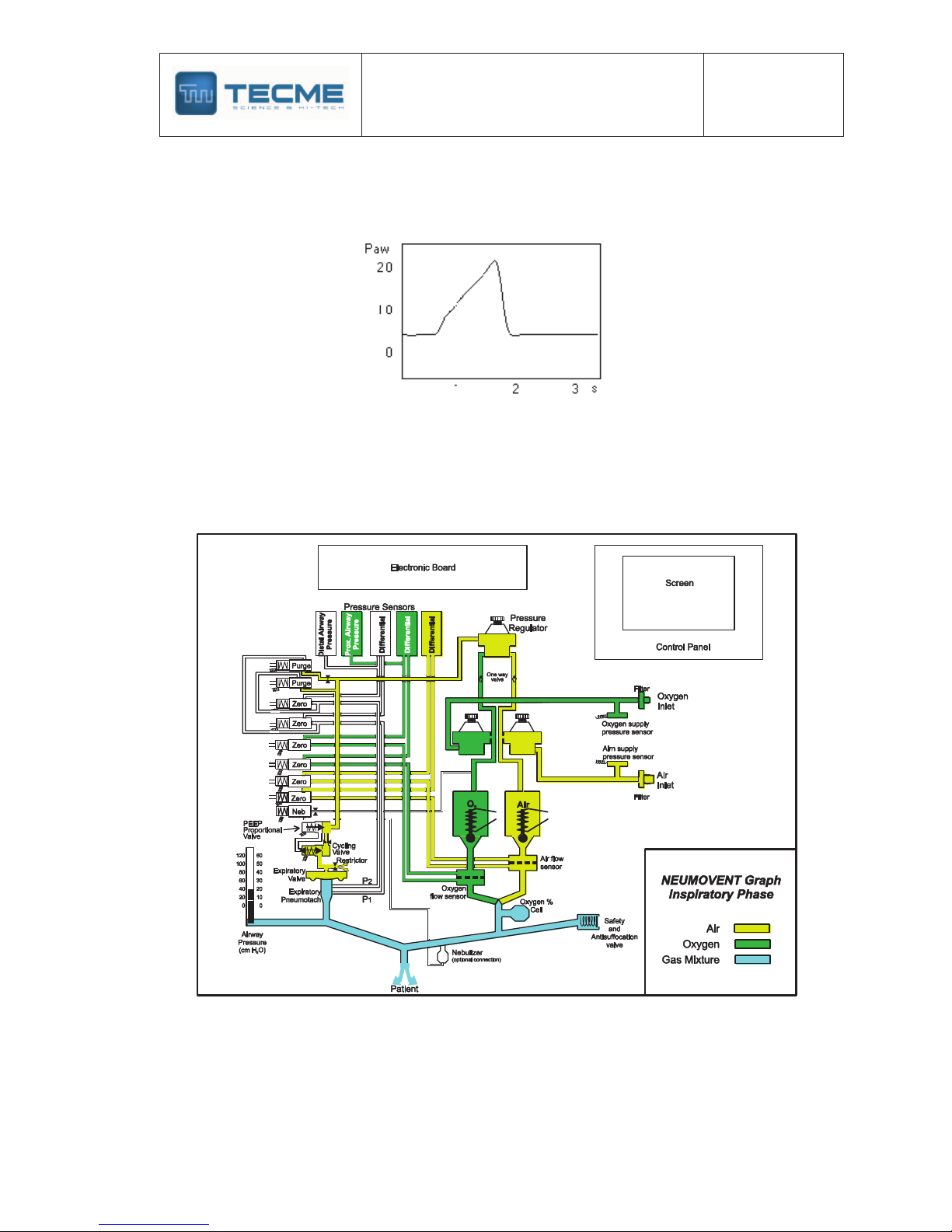
The expiratory phase can be modifying adding Positive Pressure at the End of Expiration
(PEEP). The NEUMOVENT Graph Ventilator produces this positive pressure by means of a
digital regulation of the closing force of the expiratory valve diaphragm.
Pressure curves during ventilation with
5 cm H2O of PEEP.
TECHNICAL AND MAINTENANCE MANUAL
Graph VENTILATOR
Review : 04
Date:
09/05/06
9
TECHNICAL AND MAINTENANCE MANUAL
Graph VENTILATOR
Review : 04
Date:
09/05/06
10
TECHNICAL AND MAINTENANCE MANUAL
Graph VENTILATOR
Review : 04
Date:
09/05/06
11
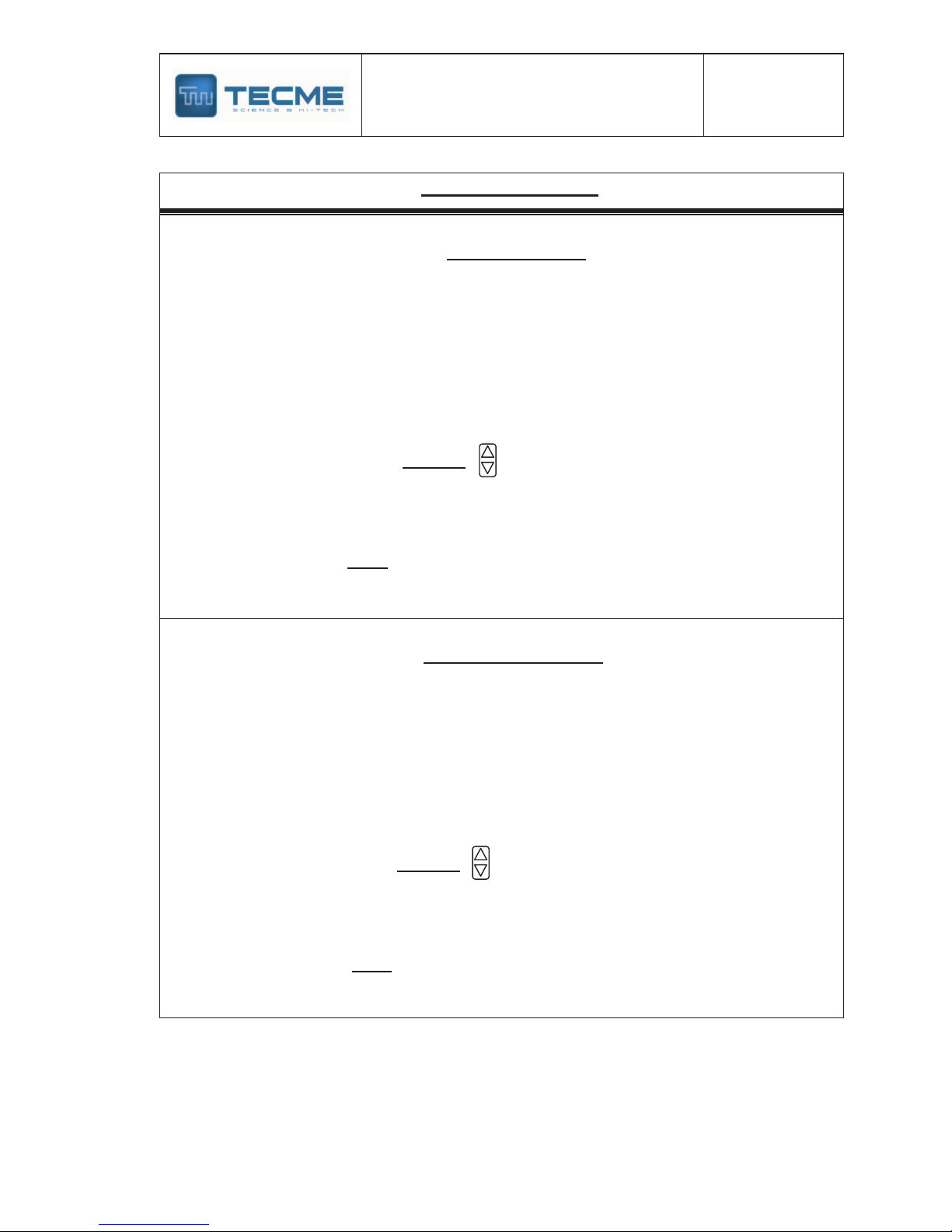
Operative modes
According to the described functional characteristics, as well as the controls and limits
assigned to this device, the following operative modes have been included. These modes
agree with the descriptions of the classic world literature, which is mentioned partly in
"Bibliography."
The division in three parts has for object to separate the groups
according to the predominant variable, volume, pressure, or
combined modes. The combined modes include modes with
participation of the two modalities and other where objectives of
tidal volume or minute volume that should be get.
Following is defined and describe the form of action for each
operative mode.

TECHNICAL AND MAINTENANCE MANUAL
Graph VENTILATOR
Review : 04
Date:
09/05/06
12
Volume
VCV Assist/Control
Definition and Operative Proceeding: It is a ventilatory mode with specific
regulation of the tidal volume. The inspiratory pressure is variable, and it depends on
the respiratory impedance to regulated volume.
During this mode, the ventilator works as a flow-controller where the selected flow
waveform is sustained during any lung compliance/resistance variation.
In this mode, the ventilator is time cycled, and the inspiratory flow is automatically
calculated and regulated. This means that for a given volume, the variations of the
inspiratory flow are obtained by means of the regulation of the inspiratory time. It also
explains why a rapid pressure drop without an inspiratory plateau marks the end of
inspiration, unless it is specifically regulated.
In the volume mode, the inspiratory flow can be changed by means of the flow
waveform control key.
The different flows are: descending ramp, constant, sine and ascending ramp. Each
of these flow waveforms also produces characteristic pressure and volume
waveforms.
This mode works with the Assist/Control characteristic, changing from a manner to
other according to the patient's demand (inspiratory effort).
If the patient’s inspiratory effort is reduced or an apnea episode is present, then, the
inspiration will be triggered by time (set machine frequency).
On the other hand, the patient's inspiratory effort could be enough to trigger the
ventilator and begin the inspiratory phase with he/she own breathing frequency and
according with the set trigger sensitivity.
Specific Controls for the VCV mode:
VT: Regulation of gas volume propelled by the ventilator in each inspiration.
Flow Waveform: To change the flow waveform.
Sigh: With selection of sigh Vt; number (1,2 or 3 successively); events per hours (5,
10, 15, 20); insp. pressure limit.
Insp. Pause: With time selection from 0.25 to 2.0 seconds.
Pressure
It comprises modes with specific regulation of the inspiratory pressure. It has two sub modes:
1) Pressure Controlled (PCV) Assist/Control
2) Pressure Support (PSV) and/or CPAP.
In both sub modes the ascending slope of the pressure can be varied with the Rise Time
control.
PCV Assisted/controlled
Definition and Operative Proceeding: In the Pressure-Controlled Ventilation mode
(PCV), the ventilator works as a positive pressure controller because the pressure
waveform remains the same when the patient’s compliance or resistance changes.
The switching from inspiration to expiration is normally regulated by time (inspiratory
cycling by time) or by pressure if the maximum safety pressure limit is reached. As in
all pressure-controlled modes, the ventilatory volume is variable and depends on the

TECHNICAL AND MAINTENANCE MANUAL
Graph VENTILATOR
Review : 04
Date:
09/05/06
13
lung size, the existent pressure gradient at the beginning of inspiration between the
upper airway and the alveoli, the respiratory system compliance and the available
inspiratory time.
The pressure waveform developed during inspiration is rectangular, being the flow of
the descending ramp type (decelerating flow). The typical pressure plotting shows a
rapid lineal increase until the set pressure limit is reached. Pressure is maintained
constant during the set inspiratory time. It cannot be changed.
This mode works with the Assist/Control characteristic, changing from a manner to
other according to the patient's demand (inspiratory effort).
If the patient’s inspiratory effort is reduced or an apnea episode is present, then, the
inspiration will be triggered by time (set machine frequency).
On the other hand, the patient's inspiratory effort could be enough to trigger the
ventilator and begin the inspiratory phase with he/she own breathing frequency and
according with the set trigger sensitivity.
In PCV it is possible to regulate the pressurization, that is to say, the rising speed of
the pressure until reaching the selected pressure limit. The pressurization is regulated
by means of the Rise Time keys, one to increase and another to diminish the speed.
Specific Controls for the PCV mode:
PCV: It regulates the pressure level.
Rise Time: Two keys to increase or to lower the pressurization time.
Pressure Support
Definition and Operative Proceeding: Pressure support ventilation is a
spontaneous ventilation mode where the patient begins and ends the inspiratory
phase; this means that he keeps control of the frequency, the duration of the
inspiration and of the tidal volume. As in all modes limited by pressure, the tidal
volume (VT) is variable, depending on the regulated pressure in relation to the
respiratory system impedance, as well as to the patient’s demand.
In this ventilator, the pressure support is programmed directly, alone or in
combination with other modes.
The patient begins the inspiratory phase according to him/her inspiratory effort and set
Inspiratory Sensitivity (pressure or flow). The inspiration end depends on the set Expiratory
Sensitivity (40. 33, 25, 15, 10 or 5% of the initial peak flow). As a safety measure, the end of
inspiration can be for pressure (3 cm H2O above the adjusted one) or time (3 seconds
maximum).
Specific Controls for the PSV mode:
PSV: It regulates the pressure level.
Rise Time: Two keys to increase or to lower the pressurization time.
Continuous Positive pressure (CPAP)
Definition and Operative Proceeding: In this mode the ventilator should generate,
by means of a partial closing of the expiratory valve, a continuous positive pressure in
the breathing circuit. When the patient inspires, the proportional solenoid valves will
open providing a flow according to the patient's demand. In this mode, the flow varies

TECHNICAL AND MAINTENANCE MANUAL
Graph VENTILATOR
Review : 04
Date:
09/05/06
14
to maintain the adjusted value of positive pressure. It can be programmed with or
without pressure support.
During the inspiratory phase, there is a decrease of the airway pressure proportional
to the demand. During the expiratory phase the airway pressure tend to increase and
becomes higher than the regulated base pressure.
Specific Controls for the CPAP mode:
PEEP/CPAP: It regulates the airway level of positive pressure.
Combined modes
Group of modes in which the patient has spontaneous ventilation with mandatory inspirations
inserted in synchronized form. Also it comprises modes with spontaneous ventilation and
minimum objectives of tidal volume or minute volume.
The combined modes that may be programmed are:
§ SIMV (VCV) + PSV
Synchronized intermittent ventilation with volume-controlled mandatory inspiration
and spontaneous inspirations with pressure support.
§ SIMV (PCV) + PSV
Synchronized intermittent ventilation with pressure-controlled mandatory inspiration
and spontaneous inspirations with pressure support.
§ MMV + PSV
Mandatory minute ventilation with pressure support. The ventilator has an automatic
control of the pressure support level in order to guarantee minimum minute ventilation
during an eventual decrease of the spontaneous breathing.
§ PSV + VT Assured
Pressure support ventilation with assured tidal volume in case of an eventual
reduction of the breathing effort. In this mode the objective is to guarantee a minimum
tidal volume from a pressure regulated inspiration.
§
Airway Pressure Release Ventilation (APRV)
It is a mode which ventilates applying periodic switching between two adjustable
levels (P-high and P-lower) of continuous positive airway pressure (CPAP) during
preset periods of time.
Synchronized intermittent ventilation with volume-controlled mandatory
inspiration and spontaneous inspirations with pressure support.
(SIMV [VCV] +
PSV)
Definition and Operative Proceeding: This mode is a combination of spontaneous
breathing with mechanical ventilation placed synchronically according the patient's
demand. In this synchronized ventilation form, the patient receives during the
mandatory breaths (forced) a preset volume sent with a preset frequency and
inspiratory time. During the spontaneous breathings the patient ventilates with
pressure support.
As in the Volume (VCV) mode, the flow waveform of the mandatory inspiration can be
changed in the course of the ventilation.
Specific Controls for the SIMV [VCV] + PSV mode:

TECHNICAL AND MAINTENANCE MANUAL
Graph VENTILATOR
Review : 04
Date:
09/05/06
15
VT: Regulation of the propelled volume by the ventilator in the mandatory inspiration.
Flow Waveform: To change the flow waveform.
PSV: Regulates the level of pressure support.
Rise Time: To vary the PSV pressurization.
Synchronized intermittent ventilation with pressure-controlled mandatory
inspiration and spontaneous inspirations with pressure support.
(SIMV [PCV] +
PSV)
Definition and Operative Proceeding: Similar to the previous mode, in this
synchronized ventilation form the patient receives, during the mandatory inspiration, a
pressure controlled inspiration with decelerating flow which is sent to the patient in a
synchronized form. During the spontaneous breathings the patient ventilates with
pressure support.
Specific Controls for the SIMV [VCV] + PSV mode:
PCV: Regulation of the pressure of the mandatory inspiration.
PSV: Regulates the level of pressure support.
Rise Time: To vary the PCV and PSV pressurization.
Mandatory Minute Ventilation with Pressure Support.
(MMV + PSV)
Definition and Operative Proceeding: It is a spontaneous ventilatory mode where
the patient breathes with pressure support at a preset initial value, and there is
regulation of a minimum minute volume. During every minute, if the volume is not
reached, the pressure support level increases progressively until that volume is
attained.
Specific Controls for the SIMV [VCV] + PSV mode:
Minute Volume: Regulation of the minimum minute volume.
PSV: Regulates the initial level of pressure support.
Rise Time: To vary the PSV pressurization.
Pressure Support Ventilation with Tidal Volume Assured. (PSV + VT Assured)
Definition and Operative Proceeding: It is a spontaneous ventilatory mode where
the patient breathes with pressure support at a given value combined with the
regulation of a target tidal volume. If during some breath, the set volume is not
reached, the descending ramp flow changes to continuous flow. This effect produces
a rise in the inspired volume until the target volume is reached with a concomitant rise
in the airway pressure.
Specific Controls for the SIMV [VCV] + PSV mode:
VT: Regulation of the minimum tidal volume.
PSV: Regulates the level of pressure support.
Rise Time: To vary the PSV pressurization.

TECHNICAL AND MAINTENANCE MANUAL
Graph VENTILATOR
Review : 04
Date:
09/05/06
16
Airway Pressure Release Ventilation (APRV)
It is a mode which ventilates applying periodic switching between two adjustable
levels (P-high and P-lower) of continuous positive airway pressure (CPAP) during
preset periods of time.
Spontaneous breathing is possible without restriction at both levels. The two levels of
positive pressure, alternating to intervals of time selected by the operator, produce
intermittent distension and passive decompression of the lungs. At the same time, and
so much during the upper or lower level, the patient can breathe spontaneously with or
without pressure support. It can by apply in ADL and PED category.
Specific Controls for the APRV mode:
PEEP/CPAP: The default values are of 5 and 0 cm H2O for P-high and P-
lower CPAP, respectively. In the screen, the first value appears in the normal
place of PEEP/CPAP. The second appears under the previous one.
To change the CPAP values the [PEEP/CPAP] key it is pressed once to
modify the high value or twice for the lower, with change of the number to
inverse video. With the key [×] of Selection sector it can be increased or
decreased the value, accepting with [Enter]. The low value can be same but
not bigger that the high.
Ti: This key completes a double function by means of which it can be adjusted
the time value of the high and lower CPAP pressure period. The values for
default are 5 and 1.5 seconds respectively. In the screen, the values appear
one above the other one in the place that corresponds at the Inspiratory Time.
To change the time values the [Ti] key should be pressed one or twice,
enabling the number of the high or low time respectively. With the key [×] of
Selection sector it can be increase or decrease the value, accepting with
[Enter].
PSV - Rise Time: During the period of high and low CPAP, the patient can
have spontaneous ventilation with or without pressure support. As default
there is 5 cm H2O of pressure support but it can be changed from 0 to 50 cm
H2O.
Sensitivity: Key to regulate the trigger sensitivity during the spontaneous
breathings. For default, the sensitivity is for flow of 3 L/min.
Backup Ventilation
Backup ventilation is a mode intended to guarantee ventilation in patients when there
is a decrease in the breathing effort or episodes of apnea during spontaneous
ventilation modes.
The warning signal, when the apnea alarm is activated, is audible and visual, and
repeats every ten seconds during five seconds. This signal is accompanied with a
message in the screen and activation of the light of apnea alarm.
This mode is of obligatory programming when some spontaneous ventilation form is
selected, as being Pressure Support, SIMV in its two forms, MMV and PSV with VT
Assured. In this way, the backup programming will offer security to the patient in case
the ventilator does not detect signal of pressure or flow to begin an inspiratory phase.
However, in SIMV it is possible to opt for the deactivation of the backup function.

TECHNICAL AND MAINTENANCE MANUAL
Graph VENTILATOR
Review : 04
Date:
09/05/06
17
As the device does not recognize difference between effort reduction and apnea,
generically this last term is used. For default the apnea time is established in 15
seconds, but it can be modified at 5, 10, 30 or 60 seconds (Menu key). The backup
ventilation for ADULT and PEDIATRIC category is made by volume or pressure
mode. In NEONATOLOGY it is made with pressure (PCV).
Common Controls to all Modes
f: Regulation of the ventilator frequency. Disabled in PSV, CPAP, MMV and PSV+VT
Assured.
Vtr: Regulation of the inspiratory flow sensitivity.
Ptr: Regulation of the inspiratory pressure sensitivity.
FIO2: Regulation of the fraction of inspired oxygen in the gas mixture.
PEEP/CPAP: To regulate a continuous positive pressure in the breathing circuit.
Manual inspiration: To start an inspiration.
Stand by: To suspend the operation of the ventilator without suppressing the set data.
Nebulization: To begin a period of flow to the nebulizer.
Alarm limits and related keys
-High Inspiratory Pressure
-Low Inspiratory Pressure
-VT high/low
-f max: High breathing frequency
-Loss of PEEP: 2, 4, 6 cm H2O.
-Apnea Time: 5, 10, 15, 30, 60 seconds.
-Silence: To suppress the alarm sound up to 60 seconds.
-Selection and Enter: Keys to increase or to lower a
parameter and to accept a selected value.
-Reset: To return some action in course.
-Ctrl: To combine functions with other key.

TECHNICAL AND MAINTENANCE MANUAL
Graph VENTILATOR
Review : 04
Date:
09/05/06
18
Alarms and Safety Mechanisms
The device has an alarm system with simultaneous messages to alert conditions that, if they
persist, they put or they can put in danger the patient's state and could require immediate
attention.
The safety mechanisms are referred to intrinsic functions of the device and comprise to
assigned program limits of each ventilatory parameter and some automatic operative actions.
Alarms
All the alarms have visual and audible signals, and are accompanied by a message on the
screen indicating the name of the alarm activated, and the possible cause and some
suggested solution. The alarms have activation priority and follow an order in accordance
with that priority. This means that if there are two or more events taking place
simultaneously, all the LED’s corresponding to those alarms is lit, but the message on the
screen is that of the alarm with a higher hierarchy. In all cases, the High Inspiratory Pressure
Alarm is considered the one with highest priority.
Some alarms have programmable values (high and/or low limits of pressures, volumes, rate),
other are automatically activated after an elapsed time. While the device remains functioning,
all the alarm events are recorded in memory and they appear in the screen of Activated
Alarms with date and hour in a maximum sequence of 50 lines.
The signals of alarm are grouped in three categories:
1) High Priority
2) Medium Priority
3) Low Priority
High Priority Signals (urgency)
They are those that require of an immediate action. They are characterized to be
activated in instantaneous form.
The alarms that are activated with signals of High Priority are the following ones:
High inspiratory pressure (Adjustable by the user)
Definition: Maximum allowed airway pressure limit.
Selection: In all the ventilatory modes.
Ventilator action:
1) Immediately activated when the inspiratory pressure reaches the set limit.
2) Immediate opening of the expiratory valve with breathing circuit decompression
to PEEP level.
Signal type: Audible, visual and warn in the screen.
Silence: It can be silenced temporarily.
Setting limits: From 10 to 120 cm H2O
Default value: According to patient category:
ADL: 40 cm H2O
PED: 30 cm H2O
NEO: 25 cm H2O

TECHNICAL AND MAINTENANCE MANUAL
Graph VENTILATOR
Review : 04
Date:
09/05/06
19
Value change: With the [Alarm Settings] key
Screen message
The audible alarm signal recovers automatically if the pressure returns to an inferior
value to the limit. The panel light signal does not disappear until the [Reset] key is
pressed.
Low inlet gas (Nonadjustable by the user)
Definition: Warns an inappropriate pressure lowering of one or both feeding gases
(oxygen or air).
Ventilator action: It is activated immediately when the air or oxygen supply
pressure is reduced below 2.7 bars. Simultaneously the gas with more pressure
passes to replace the lacking gas.
Signal type: Audible, visual and warn in the screen.
Silence: It cannot be silenced.
Screen message
Automatic reposition if the pressure returns above the limit. The light signal does not
disappear until the [Reset] key is pressed.
External power loss (Nonadjustable by the user)
Definition: Failure in the electric power of the main line. It is activated when the
current key of the device is in the ON position and the following events happen:
1) Power loss of the main line.
2) Unplugged of connection cable from mains, and
3) Burned entrance fuse.
Ventilator action: Instantaneous commutation to internal battery source of energy.
The indicative LED of the panel lights.
Signal type: Audible, light and warn on the screen.
Silence: It cannot be silenced.
Screen message
Automatic reposition if the electric power recovers. The light signal does not
disappear until the power returns.
Low battery (Nonadjustable by the user)
Definition: It is an indication that the utility time of operation with battery could be
very brief or null.
Ventilator action: There is not direct action.
Signal type: 1) Light and warn in the screen.
2) Icon indicating charge level.
Silence: It cannot be silenced.
Screen message
Continuous pressure (Nonadjustable by the user)
Definition: Maintenance of 5 cm H2O of pressure above PEEP/CPAP in the
ventilatory breathing circuit for more than 15 seconds.
Ventilator action: Decompression of the breathing circuit to the set baseline.
Signal type: Light and warn in the screen.
Silence: It cannot be silenced.
Screen message

TECHNICAL AND MAINTENANCE MANUAL
Graph VENTILATOR
Review : 04
Date:
09/05/06
20
Technical failure (Nonadjustable by the user)
Definition: Important alteration (electronic circuit or software) or burnt fuse of the
annex board.
Ventilator action: The ventilator stops to work. The screen fades. Continuous light
and audible signal is activated.
Signal type: Audible and light.
The left Technical Failure LED lit when the alteration comprises the electronic circuit
or the software.
The right LED lit when the annex board fuse burnt. No screen message.
Silence: It cannot be silenced.
Consequences: The alarm indicates to possible causes: 1) A serious alteration of
the hardware or software; 2) Burnt fuse of the annex board. The device should not
be used. Attention of specialized Service should be requested.
WARNING
When the Technical Failure alarm is activated, do not intent to use the ventilator
again. It should be sent to an authorized service.
Medium Priority Signals (caution)
They are activated with a time delay. In some the time is operator’s adjustable, in
other the time is fixed. The alarms that are activated with signals of Medium Priority
are the following ones:
Low inspiratory pressure (Adjustable by the user)
Definition: Minimum allowed airway pressure limit.
Selection: In all the modes.
Ventilator action: It is activated when the ventilator inspiratory phase pressure
stays more than 10 seconds below the set limit. If, after 30 seconds, no action is
taken by the operator, the alarm status is changed to as a High Priority Signal.
Signal type: Audible, light and warn in the screen.
Silence: It can be temporarily silenced.
Setting limits: From 3 to 99 cm H2O (from 0 in PCV).
Default value: 5 cm H2O for all patient categories.
Value change: With the [Alarm Settings] key.
Screen message
The audible alarm signal recovers automatically if the pressure returns to a superior
value of the set limit. The light signal does not disappear until the [Reset] key is
pressed.
VT high (Adjustable by the user)
Definition: Maximum allowed limit of the tidal volume impelled by the ventilator.
Selection: In all the modes.
Ventilator action: It is activated when the tidal volume of successive breathings
stays more than 10 seconds above the set limit.
Signal type: Audible, light and warn in the screen.
Silence: It can be silenced temporarily.
Setting limits: From 0.010 L up to 3.0 L.
Default value: According to the patient category:
ADL: 0.600 L; PED: 0.300 L; NEO: 0.050 L

TECHNICAL AND MAINTENANCE MANUAL
Graph VENTILATOR
Review : 04
Date:
09/05/06
21
Value Change: With the [Alarm Settings] key. The audible signal is suspended
when the pressure recovers accepted limits. The light signal does not disappear
until the [Reset] key is pressed.
Screen message
The audible signal of the alarm is suspended if the pressure returns to an inferior
value to the limit. The light signal of the alarms sector does not disappear until the
[Reset] key is pressed.
VT low (Adjustable by the user)
Definition: Minimum allowed limit of the tidal volume impelled by the ventilator.
Selection: In all the modes.
Ventilator action: It is activated when the tidal volume of successive breathings
stays more than 10 seconds below the set limit. If, after 30 seconds, no action is
taken by the operator, the alarm status is changed to as a High Priority Signal.
Signal type: Audible, light and warn in the screen.
Silence: It can be silenced temporarily.
Setting limits: From 0.001 L up to the low value of the VT high.
Default value: According to the patient category:
ADL: 0.200 L; PED: 0.100 L; NEO: 0.005 L
Value change: With the [Alarm Settings] key.
Screen message
The audible signal of the alarm is suspended if the pressure returns to a superior
value to the limit. The light signal does not disappear until the [Reset] key is
pressed.
O2 concentration high (Adjustable by the user)
Definition: Maximum allowed limit of the oxygen concentration supply by the
ventilator.
Selection: In all the modes.
Ventilator Action: It is activated when the oxygen concentration of successive
breathings stays more than 30 seconds above the set limit.
Signal type: Audible and warn in the screen.
Silence: It can be silenced temporarily.
Setting limits: 25 a 110%. Lower: 18 a 95%.
Default value: 60%
Value change: With the [Alarm Settings] key.
Screen message
O2 concentration low (Adjustable by the user)
Definition: Minimum allowed limit of the oxygen concentration supply by the
ventilator.
Ventilator Action: It is activated when the oxygen concentration of successive
breathings stays more than 30 seconds below the set limit.
Signal type: Audible and warn in the screen.
Silence: It can be silenced temporarily.
Setting limits: 18 a 95%.
Default value: 40%
Value change: With the [Alarm Settings] key.
Screen message

TECHNICAL AND MAINTENANCE MANUAL
Graph VENTILATOR
Review : 04
Date:
09/05/06
22
Apnea (Adjustable by the user)
Definition: It is a condition where the ventilator considers a breathing stop during
spontaneous ventilation modes after an adjustable period of time.
Selection: In Pressure Support, Continuous Positive Airway Pressure and
Combined Modes (optional in SIMV).
Ventilator action: Change to the selected backup mode at 5, 10, 15, 30, 60
seconds according to the set time.
Signal type: Audible, light and warn in the screen.
Silence: It can be silenced temporarily.
Default value: 15 seconds in all the categories.
Value change: Pressing the [Menu] key.
Screen message
The alarm resets automatically if the patient returns to spontaneous ventilation. The
light signal does not disappear until the [Reset] key is pressed.
Fan Failure (Nonadjustable by the user)
Definition: Detention of the fan’s operation with possibilities of electronic circuit
overheating.
Signal type: Audible, and warn in the screen.
Silence: It cannot be silenced temporarily.
Screen message
Operator Action: Check the fan correct functioning looking for foreign materials
obstructing the blades. If the failure persists, the ventilator should be replaced.
Low Priority Signals (warn)
They are activated with a time delay, in some the time is adjustable for the operator,
and in other the time is fixed. The alarms that are activated with Low Priority
Signals are the following ones:
f max (Adjustable by the user)
Definition: It regulates the spontaneous maximum breathing frequency limit. It is
also activated if the breathing frequency is adjusted with a bigger value that the limit
of the alarm.
Selection: In all the modes.
Ventilator action: The alarm is activated with light and audible signal after 20
seconds of having been surpassed the set limit. If, after one minute, no action is
taken by the operator, the alarm status is changed to as a Medium Priority Signal.
Signal type: Audible, light and I warn in the screen.
Silence: It can be silenced temporarily.
Default value: 30 bpm for all categories.
Value change: With the [Alarm Settings] key.
Screen message
The alarm resets automatically if the frequency returns to an inferior value to the
limit. The light signal does not disappear until the [Reset] key is pressed.
Low PEEP (Adjustable by the user)
Definition: Descent of the base pressure below the set value during ventilation with
expiratory positive pressure or continuous positive pressure.
Selection: In all the modes.
Ventilator action: Light and audible signal and message in the screen after 15

TECHNICAL AND MAINTENANCE MANUAL
Graph VENTILATOR
Review : 04
Date:
09/05/06
23
seconds of persisting the alteration. If, after one minute, no action is taken by the
operator, the alarm status is changed to as a Medium Priority Signal.
Signal type: Audible, and warn in the screen.
Silence: It can be silenced temporarily.
Limits: 2, 4, 6 cm H2O below the PEEP limit. In OFF it is disabled.
Default value: 4 cm H2O.
Value change: With the [Alarm Settings] key or pressing Ctrl + PEEP keys.
Screen message
Automatic reset if the pressure returns above the limit. The light signal does not
disappear until the [Reset] key is pressed.
V
E high (Adjustable by the user)
Definition: Exhaled minute volume bigger that the selected in Mandatory Minute
Ventilation mode (MMV).
Ventilator action: Warn with light and audible signal with message in the screen
after 10 seconds if the alteration persists. It generally indicates loss for the breathing
circuit or disconnection.
If, after one minute, no action is taken by the operator, the alarm status is changed
to as a Medium Priority Signal.
Signal type: Audible, light and warn in the screen.
Silence: It can be silenced temporarily.
Set limits: From 1 to 50 L/min.
Value change: With the [Alarm Settings] key.
Screen message
V
E low (Adjustable by the user)
Definition: Exhaled minute volume smaller that the one selected in Mandatory
Minute Ventilation mode (MMV).
Ventilator action: Warns after 10 seconds. It generally indicates loss for the
breathing circuit or disconnection.
If, after one minute, no action is taken by the operator, the alarm status is changed
to as a Medium Priority Signal.
Signal type: Audible, light and warn in the screen.
Silence: It can be silenced temporarily.
Regulation limits: From 1.0 L/min.
Value change: With the [Alarm Settings] key.
Screen message

TECHNICAL AND MAINTENANCE MANUAL
Graph VENTILATOR
Review : 04
Date:
09/05/06
24
Alarm Complements
§ Silence 30/60 seconds
It suspends the audible signal of some alarms. It does not suspend the sound of the
power loss and technical alarms.
§ Reset
It is a key with multiple functions, used alone or in combination with other keys. It
reestablishes or aborts changes of not accepted values.
Safety Mechanisms
The ventilator’s safety mechanisms comprise the devices that constitute it and the operative
system that governs the microprocessor. Their function is to preserve the integrity of the
procedure, making it safe and reliable.
Ventilator Components
Safety valve: It is located at the beginning of the breathing circuit. It is factory preset.
It is opened when the pressure within the patient’s circuit reaches, for any reason,
120 cm H2O. The gas enters into an internal gas collector and is expelled to the
outside.
Electronic circuit: When the microprocessors detect any failure in the electronic
circuit, not only are the alarm for technical failure activated but also the ventilator
enters into inoperative mode and all solenoid valves are deactivated.
Inspiratory relief valve (antiasphyxia): Located at the beginning of the breathing
circuit. It is opened when there is a power failure or an inoperative state, thus
enabling the aspiration of ambient air.
Operation gases exhaust: The operation gases that normally escape from some of
the internal mechanisms are directed to a common collector from where they are
expelled to the outside.
Low supply pressure of the compressed air: The lack of pressure of the
compressed air (command gas) is compensated by the compressed oxygen through
a connecting valve. The corresponding alarm is triggered, through another device, by
the lack of pressure.
Low supply pressure of the compressed oxygen: The lack of pressure of the
oxygen is compensated by the compressed air. The corresponding alarm is triggered,
through another device, by the lack of pressure.
Monitoring of the airway pressure: There are two pressure transducers located one
at the beginning (proximal pressure) and the other at the end of the patient’s service
circuit (distal pressure).
The proximal transducer commands the pressure in the Pressure-Controlled (PCV)
and Pressure Support (PSV) Modes, the limits of the maximum and minimum airway
pressure, and the positive end expiratory pressure (PEEP). It also originates the
values for the Peak, Plateau, Mean and Baseline Airway Pressure. The distal
transducer is involved in the plotting of the pressure waveforms.

TECHNICAL AND MAINTENANCE MANUAL
Graph VENTILATOR
Review : 04
Date:
09/05/06
25
Universal Voltage: The power source is self-regulated for alternate current from 100
to 240 volts.
Automatic Zero Reset: The pressure transducers are zeroed every 15 minutes or
when the operator activates this function ([Ctrl] + [Ptr-Vtr]).
Line Purge: In order to avoid any obstruction of and/or humidity in the internal
transducers, air is injected through the tubes connecting the expiratory
pneumotachograph at reset.
Operative System
The operative system, which regulates the functions of the microprocessor, is designed with
algorithms that prevent or avoid the execution of any maneuver that may have unfavorable
effects.
Memory test: Every time the equipment is turned on, a test of the RAM and EPROM
memories is run, thus ensuring the integrity of the operative system.
PEEP and Flow Calibration: Every time the equipment is turned on, the expiratory
valve is electronically calibrated to regulate the positive end expiratory pressure.
There is also a calibration of the flows that go through the expiratory
pneumotachograph.
Parameter limits: Every parameter involved in the ventilation has minimum and
maximum limits that cannot be exceeded.
Values acceptance: All selected or changed values need to be accepted by pressing
[Enter], within a maximum time of 5 seconds.
Alarm limits: Each alarm has preset or programmed limits. When they are exceeded,
in some cases the action is instantaneously suppressed (e.g.: maximum pressure
limit) or in other cases, there is activation delay time (e.g. PEEP loss), depending on
the alarm hierarchy.
Alarm activation indicators: When an alarm is activated, there is not only a light and
auditory signal but also the screen shows a message indicating the name of the
activated alarm, the possible cause and suggestions for the solution of the problem.
Watchdog: The watchdog is an independent system of surveillance of the function of
the electronic circuit.

TECHNICAL AND MAINTENANCE MANUAL
Graph VENTILATOR
Review : 04
Date:
09/05/06
26
References
1. Abraham E, Yoshihara G. Cardio-respiratory effects of pressure control ventilation in
severe respiratory failure. Chest 1989; 96:1356.
2. Amato MB, Barbas CS, Bonaza J. Volume- Assured Pressure Support Ventilation: a new
approach for reducing muscle work load during acute respiratory failure. Chest 1992;
102:1225.
3. Ashbaugh DG, Petty TL. Positive end-expiratory pressure: Physiology, indications and
contraindications. J Torac Cardiovasc Surg 1973; 65:165.
4. Branson R.D., Hess D.R., Chatbrum R.L.: Respiratory care equipment. Philadelphia: J.B.
Lippincot; 1995.
5. Brochard F; Rua F; et all. Inspiratory pressure support compensates for additional work
of breathing caused by the endotracheal tube. Anesthesiology 1991; 75:739.
6. Brochard L, Pluskawa F, Lemaire F. Improved efficacy of sponteneous breathing with
inspiratory pressure support. Am Rev respir Dis 1987; 136:411.
7. Cairo J.M., Pilbeam S.P.: Respiratory care equipment. St. Lous: Mosby; 1999.
8. Chatburn RL. A new system for understanding mechanical ventilators.Resp Care
1991;36:1123.
9. Chatburn RL. Classification of mechanical ventilators. Resp Care 1992;37:1009.
10. Downs JB, Klein EF, Desaultels E. Intermitent mandatory ventilation: a new approach to
weaning patient from mechanical ventilation. Chest 1973; 64:331.
11. Goldsmith J.P., Karotkin E.H.: Assisted ventilation of the neonate. Philadelphia: W.B.
Sauders; 1996.
12. Hewlett AM, Platt AS, Terry VC. Mandatory minute volume. Anaesthesia 1977; 32:163.
13. MacIntyre N, Nishimura M, Usada Y et al. The Nagoya conference on system designal
and patient interactions during pressure support ventilation. Chest 1990; 97:1463.
14. Murphy DF, Dobb G, Effect of pressure support ventilation on sponteneous breathing
during intermitent mechanical ventilation. Crit care Med 1987; 15:612.
15. Sanborn WG Microprocesor-based mechanical ventilation. Resp Care 1993;38:7.
16. Sassoon C. Mechanical ventilator designal and function: The trigger variable. Resp Care
1992; 37:1056.
17. Tharatt RS, Allen RP,Albertson TE. Pressure controlled inverse ratio ventilation in severe
adult respiratory failure. Chest 1988; 94:755.
18. Thompson JD. Computerized control of mechanical ventilators: closing the loop. Resp
Care 1987;32:440.
19. Tobin M.J.: Principles and practice of intensive care monitoring. New York: McGraw Hill;
1998.
20. Tobin M.J.: Principles and practice of mechanical ventilation. New York: McGraw Hill;
1994.

CHAPTER II
MAINTENANCE INSTRUCTIONS

TECHNICAL AND MAINTENANCE MANUAL
Graph VENTILATOR
Review : 04
Date:
09/05/06
27
Items to be checked during maintenance
every 5000 hours of use:
1-External check-up, clean-up and disinfection of the device.
2-Functional control.
3- Control of alarms sound:
Press “Ctrl
” + “Reset”
4-Functional inspection of keys.
5-Leds inspections:
a-Go to Analog Input in Calibration Menu ( see chapter 4°)
b-Press “Silence” key , and check all leds (except :Technical failure,
battery and charging leds)
6-Check-up the sensors following chapter 4°.
7-Check up for software updates.
8-Removal of back cover and clean-up the fan and area.
9-Inspection and clean-up porous metal filters and water trap.
10-Visual inspection of internal tubing:
Look for water and oil traces
16-Replacement of sealing joint of cabinet.
17-Reemsambl the ventilator.
18-Complete recalibration.
19-Replacement of expiratory valve.
20-Update of records and documentation.
21-Final control.

CHAPTER III
TROUBLE SHOOTING

TECHNICAL AND MAINTENANCE MANUAL
Graph VENTILATOR
Review : 04
Date:
09/05/06
29
TROUBLE SHOUTING
PROBLEM
POTENTIAL CAUSE
CORRECTIVE ACTION
Device does not
pass initial
calibration
1. Leak in the patient’s circuit.
2. Gas supply closed.
3. Occlusion of pneumatic
lines.
4. Expiratory valve control.
5.
Hose of internal circuit is
disconnected or clog
ged.
6. Pressure leak.
7. Internal electrical
connections.
1. Check the patient’s circuit.
2. Open the gas supply valve.
3.
Check inlet filters and supply hoses.
4. Check the diaphragm of the
expiratory valve. Verify if it is
correctly connected.
5. Check the equipment internal
connections.
6. Check the air-tightness of the
pneumatic set with up to 100 cm of
water. In order to do this, connect
the supply gases to the equipment,
and apply a pressure of 100 cm of
water at the outlet of the internal
pneumotachograph. If pressure
dro
ps sharply, then, there is a leak
inside the pneumatic set. Review
Safety Valve and Antisuffocation
Valve.
7.
Check the cable of the proportional
valves, and their connection. Check
voltage in the CPU connectors.
Low flow
1. Defective pressure
regulators.
2. Occlusion of pneumatic
lines or internal pneumatic
leaks.
3.
Leaks in the patient’s circuit.
4. Water in the
Pneumotachograph system.
5. Altered flow sensors.
1. Check and recalibrate pressure of
air and oxygen regulators at 2.8
kg/cm2. Check and recalibrate the
regulator pressure at 10 PCI.
2.
Check for loose or kinked filters or
hoses.
3. Check the patient’s circuit.
4. If there is water in the device,
proceed as indicated below.
5.
Check the operation of flow sensors,
and then calibrate them.
High flow
1. Defective pressure
regulators.
2. Poor flow calibration.
3. Altered
pneumotachographs.
4. Altered flow sensors.
5. Extremely high
electromagnetic interference
(EMI).
1. Check and recalibrate pressure of
air and oxygen regulators at 2.8
kg/cm2.
2.
Check to see if there is no water in
the device and recalibrate the
pneumotachograph and valves.
3. Ensure there is no water in the
device.
Check the operation of flow
sensors, and then calibrate
machine.
4. Check the operation of the flow
sensors.
5. Check for the presence of an
electronic equipment nearby that
may
be emitting electromagnetic
waves, and altering the normal
operation of the equipment.

TECHNICAL AND MAINTENANCE MANUAL
Graph VENTILATOR
Review : 04
Date:
09/05/06
30
TROUBLE SHOUTING
PROBLEM
POTENTIAL CAUSE
CORRECTIVE ACTION
Low Tidal Volume
1. Incorrect initial calibration of
the patient’s circuit.
2.
Damaged expiratory valve
or expiratory
pneumotachograph.
3.
Disconnection of the lower
hose of the expiratory
pneumotachograph.
4. Obstruction of P1.
5. Damaged flow sensors.
1. Redo initial calibration of the circuit.
2. Check expiratory valve and
pneumotachograph.
3.
Check connections of the expiratory
pneumotachograph.
4. Check permeability of P1.
5. Check flow sensors.
High Tidal Volume
1. Incorrect initial calibration.
2. Damaged expiratory
pneumotachograph.
3. Obstruction of P2.
4.
Reversed connection of P1
and P2.
5. Damaged flow sensors.
1. Redo initial calibration.
2. Check pneumotachograph.
3. Check permeability of P2.
4.
Check if P1 and P2 are correctly
connected (check they are not
inverted).
5. Check the operation of the flow
sensors.
High Inspiratory
Pressure
1. Occlusion of the patient’s
circuit.
2. High volume.
3. High rise time.
4. High inspiratory flow.
5.
Decalibrated flow sensor.
1. Check the patient’s circuit.
2. Check the volume.
3.
Regulate Rise Time according to the
patient’s resistance.
4.
Complete calibration of the device.
5.
Check complete calibration of the
device.
Low Inspiratory
Pressure
1. Disconnection of the upper
hose of the expiratory
pneumotachograph.
2.
Internal disconnection of the
flow sensor.
3. Damaged flow sensor.
1. Check connections of the expiratory
pneumotachograph.
2.
Check connections of the internal
pneumatic circuit.
3. Check the flow sensor.
High Minute
Volume
1. Disconnection of the upper
hose of the
pneumotachograph.
2. Obstruction of P2.
3.
Reversed connection of P1
and P2.
4. Damaged flow sensors.
1. Check connections of the expiratory
pneumotachograph.
2. Check permeability of P2.
3. Check if P1 and P
2 are correctly
connected (check they are not
inverted).
4. Check flow sensors.
Low Minute Volume
1. Obstruction of P1 or P2.
2. Damaged flow sensors.
3. Altered
pneumotachographs.
1. Check permeability of P1 and P2.
2. Check flow sensors.
3. Ensure there is no water in the
d
evice, and recalibrate the device
completely.
There is no PEEP
1. Damaged expiratory valve.
2.
Leaks in the patient’s circuit.
3. Defective PEEP
electrovalve.
4. Water in the PEEP
electrovalve.
1. Check expiratory valve.
2. Check the patient’s circuit.
3. Check operation of the PEEP
electrovalves in the sensors board.
4.
Check if water has entered into the
pneumatic box. If water has entered
into the valves, replace the PEEP
electrovalve.

TECHNICAL AND MAINTENANCE MANUAL
Graph VENTILATOR
Review : 04
Date:
09/05/06
31
TROUBLE SHOUTING
PROBLEM
POTENTIAL CAUSE
CORRECTIVE ACTION
High PEEP
1. Diaphragm of the expiratory
valve stuck.
2.
Obstruction of the patient’s
circuit.
3. Defective PEEP
electrovalve.
1. Replace the diaphragm of the
expiratory valve.
2. Check the patient’s circuit.
3. Check the operation of the
electrovalve.
Low PEEP
1. Leaks in the patient’s circuit.
2. Damaged
expiratory valve.
3. Leaks in the internal
pneumatic circuit.
4. Defective PEEP
electrovalve.
1. Check the patient’s circuit.
2. Check expiratory valve.
3.
Check the internal pneumatic circuit.
4. Check the operation of the
electrovalve.
Nebulizer without
flow
1. Inspiratory flow lower than 7
L/min.
2.
Disconnection in the internal
pneumatic circuit.
3. Obstruction in nebulizer.
4. Damaged solenoid valve.
1. Increase the inspiratory flow.
2.
Check the internal pneumatic circuit.
3.
Check permeability of the nebulizer
capillary.
4. Check operation of the solenoid
valve.
FiO2 different from
% FIO2
measurement
1. Decalibrated air or oxygen
proportional valves.
2. Decalibrated pressure
regulators.
3. Decalibrated oxygen
analyzer.
1. Recalibrate proportional valves, and
then recalibrate the measurement
parameters of the device.
2. Check the calibration of the
pressure regulators. Then,
recalibrate the device completely.
3. Calibrate oxygen analyzer.
Blower failure
1. Back fan disconnected or
blocked.
2. Damaged back fan.
1. Check fan and check connections.
2. Replace fan by
one with the same
features.
Low battery charge
1. Low battery charge.
2. Damaged battery.
3. Battery disconnected.
4. Electrical failure.
1. Charge the battery for 12 hours, and
if it does not become charged,
replace with new one.
2.
Replace the battery with a new one.
3. Check the battery connections.
4. Check charge voltage (13 0.5 V).
Screen does not
work
1. Burnt screen.
2. Bad contact in display
connections.
1. Replace the display with a new one.
2.
Check and clean the contacts of the
different jacks of the display.
Emergency
ven
tilation
or technical failure
1. Failure of an electrical
component.
2.
Bad contact of an electronic
component or cable.
3.
Too much dirt inside the
device.
4. Extremely high
electromagnetic interference
(EMI).
1. Check the condition of the electronic
components of the
sensors board,
ancillary board and CPU board.
2. Check soldering of wires and
electronic components.
3.
Clean all the inside of the device,
and clean the jacks.
4.
Check for the presence of electrical
devices nearby.

TECHNICAL AND MAINTENANCE MANUAL
Graph VENTILATOR
Review : 04
Date:
09/05/06
32
TROUBLE SHOUTING
PROBLEM
POTENTIAL CAUSE
CORRECTIVE ACTION
Water in the device
1. Water has entered
through the air or
oxygen supply.
2.
1. Open the device and
clean all pneumatic
components (2.8kg/cm2
pressure regulators,
proportional valves,
nonreturn valves, 10 PSI
regulator,
pneumotachograph,
meshes of
pneumotachograph)
Then, recalibrate the
device completely.
Not all LED’s of the keyboard
are lit.
1. Burnt LED’s.
2.
Disconnected key board
jack.
3.
1. Disassemble the device
and check and replace all
burnt LED’s.
2.
Check the connection of
the key board to the
CPU, and clean contacts.
3.
Autocycling of device
1. Incorrect initial
calibration.
2. Leak in the patient
circuit
3. Extremely high
electromagnetic
interference (EMI).
4.
Inadequate sensitivity.
5.
1. Redo initial calibration.
2.
Check the patient circuit.
3. Check if there i
s a high
emission electromagnetic
equipment nearby that
may be interfering with
the device.
4. Set an adequate
sensitivity.
Irregular baseline flow
1. Decalibrated device.
2. Decalibrated
proportional valves.
3.
1. Recalibrate
pneumotachographs,
proportional valves a
nd
FO2.
2.
Recalibrate proportional
valves and FO2.
Transitory failure in the reading
of pressures, volumes with
autocycling.
1. Extremely high
electromagnetic
interference (EMI).
2.
1. Check if there is a high
emission electromagnetic
device nearby.

CHAPTER IV
SENSOR VERIFICATION

TECHNICAL AND MAINTENANCE MANUAL
Graph VENTILATOR
Review : 04
Date:
09/05/06
33
Sensor Inspection
Access to the Calibration Menu
When the device is off, press the “Reset
” key, and turn it on while keeping the key pressed.
The message “Enter Code” will be displayed on the screen. At that moment, press any key four
times.
A message will then be displayed warning that the code entered is incorrect.
Press any key to continue.
At that moment, the calibration menu is displayed on the screen.
Choose the option “Analog Inputs” with the “selection
” keys
The readings of the sensors are disp
layed in this window, and it is also possible to manually open and
close the air and oxygen proportional valves.
Opening and Closure of Proportional Valves
Select the window “Analog inputs” in the Calibration menu, and then enter into the menu by pres
sing
the “Enter” key.
Analog Inputs Screen:
Air Flow:
0091
Serial No: 0333 31 008
Oxy Flow:
0080
REV:G1-2N-030410-1N
Right press:
0390
Calibrated:10/04/03 By: HA
Left Press:
0441
Exp Flow:
0069
Oxy Source:
0930
Air Source:
Power Source:
0930
0881
Oxy Cell:
0000
Air Val=
0
fan : 0
OxyVal =
0
SuffVal =
600
PeepVal =
0
Load : No
Source : Mains
Fan : OK
61hs
In the lower left corner of the “Analog Inputs” window, there is an4-
line column. Each line is identified.
The numbers shown correspond to the opening value of the respective valve. When it is zero, the
valve is closed.
- With the “selection
” keys a valve may be chosen. A red bar will appear over the chosen
valve on the screen, then press “Enter
” key.

TECHNICAL AND MAINTENANCE MANUAL
Graph VENTILATOR
Review : 04
Date:
09/05/06
34
Sensor Inspection
-
The value for the opening of the chosen valve may be increased or decreased with selection keys
This opening value may range between 0 (Closed Valve) and a maximum of 4095 (Valve completely
opened).
If press “ctrl” +“selection” the values go up or dawn in tens.
-
All valves (Opening value = 0) may be closed with the “Reset” key.
The
“AirVal” line corresponds to the air proportional valve.
The
“OxyVal” line corresponds to the oxygen proportional valve.
The
“SuffVal” line corresponds to the antisofocation valve
The
“PeepVal” line corresponds to the PEEP proportional valve.
Air and Oxygen Valves (AirVal and OxyValv)
When the opening value is increased with a value ranging between 0 and 4095, we will notice that the
valve remains closed while the opening value is lower than 900 units (approximately). When the
opening exceeds this value, the valve begins to be opened progressively (air begins to flow through the
inspiratory outlet
) until the maximum value is reached (greater than 16
0 L/min), i.e., when the opening
value reaches 4095 units.
The valve can then be closed using the
“Reset”.
Sensors Check
In the upper left corner of the window, there is an 8
-line column.
Each lines
shows the digitalized readings of the flow and pressure
. These readings will vary depending
on the flows or pressures being applied on the sensors.
When there are no supply gases connected to the device, the readings given by these sensors are
the ones
shown in the following table:
The second column
shows a value equal to the first one
but multiplied by four (do not take this into account).
Air Flow:
0091 0364
Oxy Flow:
0080 0320
Right press:
0390 1562
Left Press:
0441 1767
Exp Flow:
0069 0278
Oxy Source:
0930 0900
Air Source:
0930
Power Source:
0881 3525
Oxy cell:
0000 0000
Table :1
TECHNICAL AND MAINTENANCE MANUAL
Graph VENTILATOR
Review : 04
Date:
09/05/06
35
Sensor Inspection
Air Flow Sensor:
1) - Disconnect the supply gases from the device.
- Check if the reading of the “Air Flow”
is a stable value in correspondence with that indicated
in Table 1.
2) - Connect the supply gases to the device.
- Select the “AirVal”.
- Open it progressively with “selection
” . When the air starts to flow through the in
spiratory
outlet, the reading of the air flow begins to increase until the opening value of the valve reaches
the maximum value (maximum flow). Check the maximum value reached in the air flow reading;
it is usually greater than 800 units.
3) - Close valves with "Reset
" Key.
Oxygen Flow Sensor:
1) - Disconnect the supply gases from the device.
- Check if the reading of the “Oxi Flow”
(Line 2) is a stable value in correspondence with that
indicated in Table 1.
2) - Connect the supply gases to the device.
- Select the “OxyVal”.
- Open it progressively with “selection
” .
When the air starts to flow through the inspiratory
outlet, the reading of the oxygen flow begins to increase until the opening value of the valve
reaches the maximum value
(maximum flow). Check the maximum value reached in the oxygen
flow reading; it is usually greater than 800 units.
3) - Close valves with "Reset
" key.

TECHNICAL AND MAINTENANCE MANUAL
Graph VENTILATOR
Review : 04
Date:
09/05/06
36
Sensor Inspection
Expiratory Flow Sensor (ExpFlow):
1) - Disconnect the supply gases from the device.
- Check if the reading of the “Exp Flow
” is
a stable value in correspondence with that indicated
in Table 1.
2) -
Cover with a finger exerting pressure in port “P2”of the device and check if the expiratory flow
reading decreases to zero.
3) - Cover with a finger exerting pressure in port “P1”of the device and check if the reading
increases. With a pressure of 6 cmH2O in this port, the expiratory flow reading will be of 900
units approximately.
4) - Close valves with "Reset
" Key.
Power Source:
1) - Press “Neb” key to put the device in battery mode.
2) - Press “Stby” key to put the battery under charge.
3) - Check if the reading off the “Power Source” is not under 750.
4)- Close valves with "Reset" key.
Nebulizer:
1)-Press “Ti
” key.
2)-Check if there is flow in nebulizer outlet.
3)-Close valves with "Reset
" key.
Purging:
1)-Press “I:E
” key.
2)-Check if there is flow in P1 and P2 outlet.
3)-Close valves with "Reset" key.

TECHNICAL AND MAINTENANCE MANUAL
Graph VENTILATOR
Review : 04
Date:
09/05/06
37
Sensor Inspection
Pneumotacograph:
AirVal and OxyVal:
1) -Connect the flow analyzer in the Patient outlet (Fig.:1).
2)-Open the air/Oxy valve until 160 L/min.
3)-Check if the reading of the first column Air Flow is below 1024.
4)- Close valves with "Reset" key.
Peep valve (Peepval):
1)-Connect the pressure analyzer in the inspiratory outlet (Fig.:2) .
2)-Select PeepVal
2)-Open it progressively with “selection
” .
3)-Check the maximum value of the pressure must be between 40 and 70 cmH2O.
4)- Close valves with "Reset" key.
Inspiratory valve:
1)-Connect the pressure analyzer in the inspiratory outlet (Fig.:2).
2)-Open it with “fiO2” key.
3)-Check the maximum value of the pressure must be between 70 and 130 cmH2O.
4)- Close valves with "Reset" key.
Fig.:1
Flow
Analyzer
Ventilator
Patient outlet
Pressure analyzer
Ventilator
Inspiratory outlet
Fig.:2

TECHNICAL AND MAINTENANCE MANUAL
Graph VENTILATOR
Review : 04
Date:
09/05/06
38
Sensor Inspection
Proportional valves:
AirVal:
1)-Press the “Reset” key.
At that moment, the Calibration Menu is displayed on the screen.
2)-Choose the option “Air Val” with the “selection
” keys
3)-Put target value in 5 L/m and press the “fiO
2
” key.
4) - The valve must be open.
5)-Press the “Reset
”
key to finish and press one more time to go back to the calibration menu.
OxyVal:
Idem AirVal

CHAPTER V
EQUIPMENT OPENING AND
CLOSURE

TECHNICAL AND MAINTENANCE MANUAL
Graph VENTILATOR
Review : 04
Date:
09/05/06
39
How to Open and Close the Neumovent Graph Ventilator
Operation
Description
10
Removal of back cover:
Open the ventilator by removing the eight screws located in the positions indicated
in the figure.
Position of the device for the disconnection of the cables:
- Lay the device down with the face downwards, and place it on foam rubber.
- Lay the back cover down as indicated in the figure, and disconnect the cables.
Adjustment screw and
flange - A.C. cable
Device
Foam Rubber
Back Cover

TECHNICAL AND MAINTENANCE MANUAL
Graph VENTILATOR
Review : 04
Date:
09/05/06
40
How to Open and Close the Neumovent Graph Ventilator
Operation
Description
10
Disconnect the following cables:
- Con.6, battery cable of the Ancillary Board.
- Con.12, speaker cable of the CPU Board.
- Con.5, fan cable of the Ancillary Board.
- Con. 8, RS-232 cable of the CPU Board.
Battery Cables
Speaker Cables
Fan
1
Battery
Fan Cable
Speaker
RS-232 Cable

TECHNICAL AND MAINTENANCE MANUAL
Graph VENTILATOR
Review : 04
Date:
09/05/06
41
How to Open and Close the Neumovent Graph Ventilator
Operation
Description
20
Separation Back Cabinet – Front Cabinet:
- Remove the screws indicated with arrows in Fig.:2-A-B.
- Disconnect the cables as indicated under operation 30:
Front View
Rear View
Fig.:2-A
Fig.:2-B
Fig.:2-C
Front Cabinet
Rear Cabinet

TECHNICAL AND MAINTENANCE MANUAL
Graph VENTILATOR
Review : 04
Date:
09/05/06
42
How to Open and Close the Neumovent Graph Ventilator
Operation
Description
30
Separation Front Cabinet – Back Cabinet, electrical part
To Con 7 of Ancil Board
To power source
Ground Cables
PNEUMATIC BOX
CPU
BOARD
Con.14
ANCIL
BOARD
Con.3
Con.7
Con.6
Con.5
ON-OFF Cables
POWER
SOUCE
Proportional Valves
Cables
AC Cable
Front
Gabinet
ON-OFF Cables
Proportional Valves
Cables
AC Cable
Back
Gabinet
To Con14 of CPU Board
Fig.:3-A

TECHNICAL AND MAINTENANCE MANUAL
Graph VENTILATOR
Review : 04
Date:
09/05/06
43
How to Open and Close the Neumovent Graph Ventilator
Operation
Description
40
Separation Front Cabinet – Back Cabinet, pneumatic part
o
2
air
nebulizer
entrada
salida
P2
P1
Neumo inspiratory
(-)
(+)
(+)
(-)
Espiratory V.
0,7 Kg/cm
2
F.scape
Fig.:4-A
Pneumatic Box
Nebulizer
P1 P2
Espiratory V.
aire
o
2
Front Cabinet
10PSI
O2 AIR
Gas
Inlet
Back Gabinet
O2
AIR
Antisofocation
Val.

TECHNICAL AND MAINTENANCE MANUAL
Graph VENTILATOR
Review : 04
Date:
09/05/06
44
How to Open and Close the Neumovent Graph Ventilator
Operation
Description
40
Cabinets Separated
Fig.:4-B
Front Cabinet
Rear Cabinet
Cabinet sealing joint

TECHNICAL AND MAINTENANCE MANUAL
Graph VENTILATOR
Review : 04
Date:
09/05/06
45
How to Open and Close the Neumovent Graph Ventilator
Operation
Description
50
Separation Pneumatic Box - Front Cabinet, pneumatic part:
- Disconnect the tubes indicated in Fig.:5-A
o
2
air
nebulizer
inlet
outlet
P2
P1
Neumo Inspiratory
(-)
(+)
(+)
(-)
Expiratory V.
10 psi Reg.
G.Exh.
Fig.:5-A
Outlet Manifold
Pneumatic Box
Nebulizer
P1 P2
Expiratory V-

TECHNICAL AND MAINTENANCE MANUAL
Graph VENTILATOR
Review : 04
Date:
09/05/06
46
How to Open and Close the Neumovent Graph Ventilator
Operation
Description
50
Separation Outlet Manifold – Box – Front Cabinet:
-Remove the screws indicated in Fig.:5-B
Pneumatic Box
Front Gabinet
Fig.: 5-B

TECHNICAL AND MAINTENANCE MANUAL
Graph VENTILATOR
Review : 04
Date:
09/05/06
47
How to Open and Close the Neumovent Graph Ventilator
Operation
Description
50
Separation Outlet Manifold – Box – Front Cabinet:
-Disconnect tubes 1, 2, 3, and 4, and remove the outlet manifold, Fig.:5-C
1
2
o
2
air
nebulizer
entrada
salida
P2
P1
Neumo inspiratory
(-)
(+)
(+)
(-)
V. Espiratory
Reg.10 psi
F.scane
1
2
3
3
4
4
Outlet Manifold
Pneumatic Box
Front Cabinet

TECHNICAL AND MAINTENANCE MANUAL
Graph VENTILATOR
Review : 04
Date:
09/05/06
48
How to Open and Close the Neumovent Graph Ventilator
Operation
Description
60
Disconnection: Pneumatic Box – Front Cabinet, electrical part:
1- Disconect cables J1 , J2 y S/N
2- Disconect power cable ancillary board – Pneumatic Box
3- Disconnect flat (ribbon) cables, CON 4 and CON 10, box, of the CPU board
Fig. 6-A
CON 14
CON 12
CON 8
CON 9
CON 7
CON 6
CON 5
CON 10
CON 1
CON 2
CON 4
CON 4
J1
J2
CPUBoard
S/N
Ancil Board
Front
Gabinet
CoaxialCables
Pneumatic Box
Power source

TECHNICAL AND MAINTENANCE MANUAL
Graph VENTILATOR
Review : 04
Date:
09/05/06
Operación
How to Open and Close the Neumovent Graph Ventilator
70
1- Desconect Con2 cables
2-
Desconect Con1,Con3 and Con5 flat (ribbon)cables of CPU board 3- Remove the 4 screws indicated
4-Then, move the boards in the direction indicated by the arrows so as to remove them
CON 14
CON 12
CON 8
CON 9
CON 7
CON 6
CON 5
CON 1
CON 2
CON 4
J1
J2
CPU Board
S/N
Ancil Board
Ffront
Gabinet
CON 3
CON 5
Move the boards
In this direction
Position 2
(Side shield
)
Positiion 1
(Box Ground cable)
Power
Source
From Con 3 cable
of
Ancil board
1
2
To
J2 in power source
Con3
Remove the screws
indicated

TECHNICAL AND MAINTENANCE MANUAL
Graph VENTILATOR
Review : 04
Date:
09/05/06
50
How to Open and Close the Neumovent Graph Ventilator
Operation
Description
80
Removal of Shield
1-Remove the 5 screws indicated in Fig.:8-A.
2-Remove the shield, Fig.:8-B.
Fig.:8-B
Fig.:8-A
Shield
Front Cabinet

TECHNICAL AND MAINTENANCE MANUAL
Graph VENTILATOR
Review : 04
Date:
09/05/06
51
How to Open and Close the Neumovent Graph Ventilator
Operation
Designation
90
Removal of Keyboard Board
1- Disconnect the cables indicated in Fig.:9-A.
2- Remove the Keyboard Board, by removing the 20 screws that attach it to the panel.
Source Board – Inverter Board Cables
Inverter Board–DisplayCables
Fig.:9-A
Fig. 9-B :
Nut
Filler
Screw
Keyboard board
Panel
Nut, do not remove

TECHNICAL AND MAINTENANCE MANUAL
Graph VENTILATOR
Review : 04
Date:
09/05/06
52
How to Open and Close the Neumovent Graph Ventilator
Operation
Description
100
Removal of Shield- Front Cabinet
1- Remove the washer screws and foam filler.
2-
Do not remove the hexagonal fillers since they do not hold the panel.
3-
Remove the nuts which hold the flanges, and finally remove the flanges an
d white head
screws.
- The panel can be now removed. Proceed with extreme care since it is attached to the cabinet
with silicone sealer.
Flange
Flange
Fig.:10-A

TECHNICAL AND MAINTENANCE MANUAL
Graph VENTILATOR
Review : 04
Date:
09/05/06
53
How to Open and Close the Neumovent Graph Ventilator
Operation
Description
110
Removal of the gas control set
1- Disconnect cables 1 and 2 from the connector indicated in Fig.:11-A.
2-Remove the screws indicated in Fig.:11-A.
1 2
B
Gas
Control set
A
Screws
Conector
O2
AIR
Back Gabinet
screws
Proportional Valves
Air and Oxigen
Regulator
Security Valve
Pneumotacograf

CHAPTER VI
DETAIL OF ASSEMBLIES

TECHNICAL AND MAINTENANCE MANUAL
Graph VENTILATOR
Review : 04
Date:
09/05/06
54
ASSEMBLY DETAILS
Code:1782 A1V Name: Oxygen inlet
No.
CODE
DESCRIPTION
1
1782 M1V
IMP. GAS INLET, BODY WITH 6 HOLES
2
1781 M1V
IMP. GAS INLET, BODY
3
319 M2V
9/16 CONNECTOR
4
206 C1V
POROUS METAL FILTER
5
207 C0V
2120 O´RING
6
1199 M1T
M4x0.7x8 SCREW
6
1
5
4
5
2

TECHNICAL AND MAINTENANCE MANUAL
Graph VENTILATOR
Review : 04
Date:
09/05/06
55
ASSEMBLY DETAILS
Code:1781 A1V Name: Air inlet
No.
CODE
DESCRIPTION
1
1782 M1V
IMP. GAS INLET, BODY WITH 6 HOLES
2
1781 M1V
IMP. GAS INLET, BODY
3
659 M2V
3/4 CONNECTOR
4
206 C1V
POROUS METAL FILTER
5
207 C0V
2120 O´RING
6
1199 M1T
M4x0.7x8 SCREW
1
5
4 2 3
6

TECHNICAL AND MAINTENANCE MANUAL
Graph VENTILATOR
Review : 04
Date:
09/05/06
56
ASSEMBLY DETAILS
Code: 2200-A1V Name: Expiratory valve
No.
CODE
DESCRIPTION
1
2657 A1V
COMPLETE EXPIRATORY VALVE COVER
2
1111 G0V
PEEP VALVE DIAPHRAGM
3
2658 A1V
COMPLETE EXPIRATORY VALVE BODY
4 M 3x6x120 mm CRYSTAL TUBE
1
2
3
4

TECHNICAL AND MAINTENANCE MANUAL
Graph VENTILATOR
Review : 04
Date:
09/05/06
57
ASSEMBLY DETAILS
Code: 0554-A1V Name: 2.8Kg/cm2 and 0.7 Kg/cm2 Regulator’s
1
2
3
4
5
6
7
8
9
10
11
12
13
14

TECHNICAL AND MAINTENANCE MANUAL
Graph VENTILATOR
Review : 04
Date:
09/05/06
58
ASSEMBLY DETAILS
Code: 0554-A1V Name: 2.8Kg/cm2 and 0.7 Kg/cm2 Regulator’s
No.
CODE
DESCRIPTION
1
0480 M1T
ADJUSTING SCREW
2
0253 C0U
M 4x0,7 HEXAGONAL NUT
3
0560 C0A
WASHER
4
0491 M1V
REGULATOR COVER
5
1326 M1 R
ADJUSTMENT SPRING
6
0511 G0V
REGULATOR DIAPHRAGM
7
1141 M1T
M 4x0.7x7 ROUND HEAD SCREW
8
0477 M1V
REGULATOR 1st STAGE SEAT
9
0217 C0O
2020 O’RING
10
0475 M2V
CHOKE
11
0484 M1R
CELL SPRING AND REGULATOR
12
0562 C0T
M4x0.7x35 ALLEN SCREW
13
0490 M2V
REGULATOR BODY
14
0476 M1V
PIN

TECHNICAL AND MAINTENANCE MANUAL
Graph VENTILATOR
Review : 04
Date:
09/05/06
59
ASSEMBLY DETAILS
Code: 2460-A1V Name: Line nonreturn valve
No.
CODE
DESCRIPTION
1
2138 M1V
BODY
2
2305 G1V
CHOKE
3
2182 M1R
SPRING
4
211 C0V
2009 O’RING
5
2137 M1V
COVER
1
2
3
4
5

TECHNICAL AND MAINTENANCE MANUAL
Graph VENTILATOR
Review : 04
Date:
09/05/06
60
ASSEMBLY DETAILS
Code: 2294-A1V Name: Pneumotacograph
N°
CÓDIGO
DESIGNACIÓN
1
2781-M1V
Left cover
2
2453-A1V
Mesh holder
3
2772-M1V
Pneumotacograph body
4
2773-A1V
Right cover
5
2493-A1V
Safety valve
2
1
3
4
5

TECHNICAL AND MAINTENANCE MANUAL
Graph VENTILATOR
Review : 04
Date:
09/05/06
61
ASSEMBLY DETAILS
Code:2545-A1V Name: Complete NV-Graph proportional valve
No.
CODE
DESCRIPTION
1
2547 A1V
SOLENOID SET
2
2548 A1V
MAIN PROPORTIONAL VALVE
1
2

TECHNICAL AND MAINTENANCE MANUAL
Graph VENTILATOR
Review : 04
Date:
09/05/06
62
ASSEMBLY DETAILS
Code: 2493-A1V Name: Safety valve
No.
CODE
DESCRIPTION
1
2488 M1 V
SAFETY VALVE, PRESS
2
2486 M1 V
SAFETY VALVE, BODY
3
2489 M1 V
SAFETY VALVE, SPRING
4
2487 M1 V
SAFETY VALVE, CHOKE
5
0515-C0O
O-ring 2-013
5
4
3 2 1

CHAPTER VII
ELECTRONIC BOARDS: DETAIL

TECHNICAL AND MAINTENANCE MANUAL
Graph VENTILATOR
Review : 04
Date:
09/05/06
63
ELECTRONICS DETAILS
Code: 2410-A1V Designation: CPU-Board
Without components Q:14,35 put it in the reverse position.
Optional Con3 : flat cable 20 conductors. of 70mm

TECHNICAL AND MAINTENANCE MANUAL
Graph VENTILATOR
Review : 04
Date:
09/05/06
64
ELECTRONICS DETAILS
Code: 2410-A1V Designation: CPU-Board
Qty
Code
Obs.
Placed
1
3V 35mAh LITIO
Batery
BT1
1
BUZZER TYD12
Piezoeléctrico con osc.12V
paso .3” diametro máx .65”
BUZZER
1
STMM-110-02-G-D
CONECTOR
CON3
1
TCSD-10-D-09.00-01-F-N
CABLE
2
Jack:413990-2
Plug:413985-1
J1;J2
1
103309-1
M: CONECTOR 10 P/C
CON1
1
103309-2
M: CONECTOR 14 P/CI
CON4
1
103309-6
M: CONECTOR 26 P/CI
CON10
1
103308-8
M: CONECTOR 40 P/CI
CON5
1
26-61-4020
M: CONECTOR MOLEX 2
P/CI (opc. 26-65-4020)
1
26-61-4100
M: CONECTOR MOLEX 10
P/CI (opc. 26-65-4100)
CON2
2
26-61-4030
M: CONECTOR MOLEX 3
P/C (opc. 26-65-4030)
CON14
8
1µf x 50V
Cap. Multicapa paso .2” (5
mm) radial
C:1;4;100;103;106;107;10
8;109;
36
0,1µf x 50V
Cap. montaje superficial
Encap.1206
C:5;6;7;8;9;10;11;12;14;
15;16;17;18;19;20;22;23;
24;25;26;27;28;37;38;41;
43;44;45;46;47;50;51;52;
54;56;85
6
0,1µf x 50V
Capacitor SCP (5 mm)
radial Siemens
C:2;3;13;21;101;102
14
1nf x 50V
Cap. montaje superficial
Encap.1206
C:36;39;86;87;88;89;90;9
1;92;93;94;95;96;97
2
10nf x 50V
Cap. montaje superficial
Encap. 1206
C:40;58
2
6,8pf
Cap. mica plate
C:42;48
5
4,7µf x 16V
Cap. de tantalio
C:49;53;55;57;110
7
10µf x 16V
Cap. de tantalio
C:59;61;62;68;69;70;71
1
15pf
Cap. mica plate
C:60
1
22pf
Cap. mica plate
C:63
1
220pf
Cap. mica plate
C:64
1
2200µf x 16V
Cap. Electrolítico paso .25”
radial
C:111
3
1N4148
Diodo señal
D:1;6;7
1
LM385-1.2V
Diodo de referencia
D:2
5
1N4003
Diodo usos generales
D:3;4;5,8;10
11
RXE030
Polyswitch
F:6;7;8;9;10;11,13;14;15;
16;17
1
8,2µHy
Choque axial paso .3”
L:1

TECHNICAL AND MAINTENANCE MANUAL
Graph VENTILATOR
Review : 04
Date:
09/05/06
65
ELECTRONICS DETAILS
Code: 2410-A1V Designation: CPU-Board
Qty
Code
Obs.
Placed
4
BC337
Transistor
Q:1;10;15;28
18
BC327
Transistor
Q.3;4;6;7;8;9;11;12;16;17;
18;19;20;24;25;26;27;29
2
MPSA13
Transistor
Q:14;35
1
TIP32C
Transistor
Q:30
4
TIP31C
Transistor
Q:2;5,13; 21
1
10KW
Array de 10 pines
R:3
2
10KW
Array de 8 pines
R:4;110
3
1,5W 2W
Resistencia 1% metalfilm
R:43;47,55
2
10W 1W
Resistencia 1% metalfilm
R:70;79
7
47W 1W
Resistencia 1% metalfilm
R:82;83;84;85;87;88;89
2
910W 1% 1/8W
Resistencia 1% metalfilm
R:15;8
6
1KW 1% 1/8W
Resistencia 1% metalfilm
R:2, 10; 115;116;117;118
1
2,2KW 1% 1/8W
Resistencia 1% metalfilm
R:12
2
33KW 1/8W
Resistencia 1% metalfilm
R: 5;11
1
39KW 1/8W
Resistencia 1% metalfilm
R: 112
2
56KW 1% 1/8W
Resistencia 1% metalfilm
R:9;1
1
470W 1/8W
Resistencia carbón
R:86
1
180W 1/8W
Resistencia carbón
R:119
16
560W 1/8W
Resistencia carbón
R:50;51;52;53;54;56;57;
58;60;65;67;69;74;77;78;
80
1
1KW 1/8W
Resistencia carbón
R:73
2
2,2KW 1/8W
Resistencia carbón
R:36;46
11
4,7KW 1/8W
Resistencia carbón
R:33;44;66;75;81;90;91;9
6;97;98; 109
3
8,2KW 1/8W
Resistencia carbón
R:38;92;94
8
10KW 1/8W
Resistencia carbón
R:32;37;41;48;49;64;72;1
21
2
15KW 1/8W
Resistencia carbón
R:31;39
5
22KW 1/8W
Resistencia carbón
R:22,23,26,27,40
1
33KW 1/8W
Resistencia carbón
R: 113
5
100KW 1/8W
Resistencia carbón
R:6;7;13;14;45
1
220KW 1/8W
Resistencia carbón
R:42
4
470KW 1/8W
Resistencia carbón
R:21;24;25;28
1
2,2MW 1/8W
Resistencia carbón
R:18
1
SN74HC05PWT
Lógica CMOS
U:1
2
TC551001CF-70L
Ram Estatica
U2;U14

TECHNICAL AND MAINTENANCE MANUAL
Graph VENTILATOR
Review : 04
Date:
09/05/06
66
ELECTRONICS DETAILS
Code: 2410-A1V Designation: CPU-Board
Qty
Code
Obs.
Placed
1
AT27C040-12JC
Prom OTP 512Kb x 8
PLCC32
U:3
3
OP400FY
Cuadruple amplificador
DIP14
U:4;7;13
2
25C320/P
Memoria EEPROM
U:6;5
1
S1D13503F00A100
Controlador de pantalla,
montaje superficial
U:8
1
AM188EM-40KC
Microcontrolador
U:9
1
DS1307
Reloj de tiempo real DIP8
U:10
1
MAX1202BCAP
ConversorA/D8 conversor
U:11
1
EPM7128SLC84-15
Lógicaprogramable PLCC84
U:12
1
MAX525BCAP
ConversorD/A4 conversor
U:15
1
74HC154D
Lógica CMOS, montaje
superficial
U:16
1
ADM232LJR
Conversor RS232 a lógica,
montaje
U:17
2
ULN2003A
Buffer, montaje superficial
U:18;19
1
74HC541D
Lógica CMOS, montaje
superficial
U:20
1
74HC574D
Lógica CMOS, montaje
superficial
U:21
1
10MHz
Cristal controlador de
pantalla
Y:1
1
32768Hz
Cristal de reloj de tiempo
real
Y:2
1
24MHz
Cristal microcontrolador
Y:3
1
822473-3
zócalo PLCC32
U:3
1
822473-7
zócalo PLCC84
U:12
1
2621 M1 V
DISIPADOR EN "L"
1
2622 M1 V
DISIPADOR EN "U"
1
PLACA BASE

TECHNICAL AND MAINTENANCE MANUAL
Graph VENTILATOR
Review : 04
Date:
09/05/06
67
ELECTRONICS DETAILS
Code : 2109-A1 V Designation: Ancillary Board

TECHNICAL AND MAINTENANCE MANUAL
Graph VENTILATOR
Review : 04
Date:
09/05/06
68
ELECTRONICS DETAILS
Code:2109-A1V Designation:Ancillary Board
Qty.
Obs.
Placed
2
Resistencia 1% metalfilm
R2,R60
1
Resistencia 1% metalfilm
R3
3
Resistencia carbón
R14,R68
1
Resistencia metalfilm
R5
2
Resistencia carbón
R7,R9
13
Resistencia carbón
R8,R16,R19,R21,R24,
R26,R27,R28,R37,R38,
R41,R65,R67
2
Resistencia carbón
R10,R12
3
Resistencia carbón
R11,R13,R15
3
Resistencia carbón
R6,R22,R31
8
Resistencia carbón
R17,R18,R20,R30,
R33,R36,R40,R66
2
Resistencia carbón
R23,R32
1
Resistencia carbón
R25
1
Resistencia metalfilm
R29
2
Resistencia cerámica
R34,R35
1
Resistencia carbón
R39
3
Resistencia 1% metalfilm
R57,R58,R59
2
Resistencia 1% metalfilm
R61,R69
2
Resistencia carbón
R62,R63
1
Resistencia carbón
R64
1
Regulador 8V 1Amp
U1
1
Switching regulador
U2
1
Regulador
U3
1
Reg. positivo ajustable
U4
1
Reg. positivo
U5
2
Cuadruple amplificador oper.
U6,U7
2
Cab. Cilindrica (1493 C0T)
3
Tornillo M3x0.5x8 c.c.
2
Tornillo M3x0.5x12 c.c.
7
Tuerca M3x0,5
1
Terminal anillo
16cm
Cable plano 10 Cond.
9cm
Cable plano 2 Cond.
1
Con. plast.. HBR MINI AMP 2 vias
2
Term. MCH MINI CILIN. AMP

TECHNICAL AND MAINTENANCE MANUAL
Graph VENTILATOR
Review : 04
Date:
09/05/06
69
ELECTRONICS DETAILS
Code:1799-E2V rev7 Designation: Sensor Board, electric part.
Designation: Sensor Bard,pneumatic part.
TECME S.A.
P/N 1799E2V
Rev 6
Differentials sensors
pressure

CHAPTER VIII
CALIBRATION

TECHNICAL AND MAINTENANCE MANUAL
Graph VENTILATOR
Review : 04
Date:
09/05/06
70
Measurement, Inspection and Test Equipment
1-Flow analyzer (TSI Certifier)
2-Oximeter
3- Medical grade Air
4-Oxigen
5-Reusable adult respiratory circuit
6-O2 cell
7-5 Kg./cm2 Pressure regulator
8-100 cm. H2O Pressure regulator
Remarks:
-
The EMI must be periodically calibrated by an official organization and the calibration
must be recorded and filed.
-The air used must be free of oil, humidity, and particles larger than 0.3 m
Procedure for Initial Calibration and Setup
Neumovent Graph Ventilator
Operación
Descripción
10
Access to the Calibration and Setup Menu:
When the device is off, press the
“Reset”
key, and turn it on while keeping the key pressed.
The next message will be displayed on the screen:
Pasword:
1- If the changes to be made are to be saved in the memory, press the following sequence
of keys:
I : E – FREEZE – VOLUME - VERT
The next message will be displayed on the screen:
Correct Pasword
PRESS ANY KEY
You will get to MENU CALIBRATION by pressing any key
TECHNICAL AND MAINTENANCE MANUAL
Graph VENTILATOR
Review : 04
Date:
09/05/06
71
Procedure for Initial Calibration and Setup
Neumovent Graph Ventilator
Operation
Description
2- If the changes in the calibration are not to be saved, press any key three times.
The next message will be displayed on the screen:
Incorrect Pasword
PRESS ANY KEY
You
will get to MENU CALIBRATION by pressing any key
20
Calibration and Setup Menu:
The calibration and setup menu displays a list in the following order:
Ajuste del reloj
Presión Ambiente
Flujo Aire
Flujo Oxigeno
Válvula Aire
Válvula Oxigeno
Sensores de Presión
Válvula PEEP
Comp. Neumo.
Entradas Analógicas
Opciones Iniciales
Numero de Serie
a-
Select the desired option with the “Selection” key
b-
Press “enter” to enter into the selected calibration screen. Then, press “Reset”
to return
to initial menu.

TECHNICAL AND MAINTENANCE MANUAL
Graph VENTILATOR
Review : 04
Date:
09/05/06
72
Procedure for Initial Calibration and Setup
Neumovent Graph Ventilator
Operation
Description
30
Clock Adjustment:
-To
changes the date and hours values:
a-
Select the desired option with the “Selection” key
b-
Press “enter” to enter and modify the values with “Selection” key
c-
Press “enter” to exit.
-If the changes are ready
Press “Menú” and the next message will be displayed on the screen:
SAVE
EXIT
Select the desired option with the
“Selection” key and press “Enter”.
-If you select
EXIT and the values was modified;
the next message will be displayed on
the screen
:
¿Exit without save changes?
[ Enter ] Accept
[ Reset ] Cancel
Select the desired option
Then, press
“Reset”to return to initial menu.

TECHNICAL AND MAINTENANCE MANUAL
Graph VENTILATOR
Review : 04
Date:
09/05/06
73
Procedure for Initial Calibration and Setup
Neumovent Graph Ventilator
Operation
Description
40
Ambient Pressure
Changes the values with
“Selection” key
Press
“Menú” and the next message will be displayed on the screen:
SAVE
EXIT
Select the desired option with the
“Selection” key and press “Enter”.
-If you select
EXIT and the values was modified;
the next message will be displayed on
the screen
:
¿Exit without save changes?
[ Enter ] Accept
[ Reset ] Cancel
Select the desired option
Then, press
“Reset”to return to initial menu.

TECHNICAL AND MAINTENANCE MANUAL
Graph VENTILATOR
Review : 04
Date:
09/05/06
74
Procedure for Initial Calibration and Setup
Neumovent Graph Ventilator
Operation
Description
50
Air Flow
a-
Connect the device outlet to a standard flowmeter Fig.:1-A (end of chapter ).
b-
Connect the inlets of the gas supply to a compressed air supply source
c-
Select the target value with “Selection” key and press “Enter”
O
pen and close the valve with “Selection” key
Low
Fast
d-
When the target value is taked press “Enter”.
e-
Select a new target and repeat the operations a-b-c.
f-
Press “Menú” and the next message will be displayed on the screen:
SAVE
EXIT
Select the desired option with the
“Selection” key and press “Enter”.
-If you select
EXIT and the values was modified;
the next message will be displayed on
the screen
:
¿Exit without save changes?
[ Enter ] Accept
[ Reset ] Cancel
Select the desired option
Then, press
“Reset”to return to initial menu.
Air Flow
Target
Apertura
0
0
0
0
Memory
Flow
Lectura

TECHNICAL AND MAINTENANCE MANUAL
Graph VENTILATOR
Review : 04
Date:
09/05/06
75
Procedure for Initial Calibration and Setup
Neumovent Graph Ventilator
Operation
Description
60
Air Valve
a-
If the valve don’t have previous calibration the next message will be displayed
on the screen
:
START
SAVE
EXIT
b-
If the valve have previous calibration then press “Menú”.
c-
Select START and press “Enter” to auto calibration begins
d-
Press “Menú” and the next message will be displayed on the screen:
SAVE
EXIT
Select the desired option with the
“Selection” key and press “Enter”.
-If you select
EXIT and the values was modified; the next message will
be displayed on
the screen
:
¿Exit without save changes?
[ Enter ] Accept
[ Reset ] Cancel
Select the desired option
Then, press
“Reset”to return to initial menu.
Air valve
Target
Apertura
0.0
0.1
0
0
Memoria
Flujo

TECHNICAL AND MAINTENANCE MANUAL
Graph VENTILATOR
Review : 04
Date:
09/05/06
76
Procedure for Initial Calibration and Setup
Neumovent Graph Ventilator
Operation
Description
70
Oxigen Valve
Do the same operations than Air va
lve.
80
Pressure Sensors
The screen will display a list of the calibration values saved in the memory which
correspond to the pressures indicated in the following table:
(zero p) (calibration p.)
(Control
Sensor) 0 100 cmH2O
(Graph
Sensor) 0 100 cmH2O
(Air
Sensor) 0 5 kg/cm2 (71 PSI)
(Ox
igen Sensor) 0 5 kg/cm2 (71 PSI)
the values on the left column, which correspond to zero pressure
Select the desired option with the
“Selection” key and press “Enter” to save the
zero
value of the four sensors
a-
Maximum value for the control sensor (right)
1-
Connect the supply pressures
2-
Select the desired option with the “Selection” key
3-
Connect a 100 cmH2O pressure at the outlet to the patient.
4-
Save the value with “Enter”.
Presssure Sensors
Derecho 0 0 0 Cm H
2
O
Izquierdo
0 0 0 Cm H
2
O
Aire
0 0 0 Kg./cm
2
Oxigeno 0 0 0 Kg./cm2

TECHNICAL AND MAINTENANCE MANUAL
Graph VENTILATOR
Review : 04
Date:
09/05/06
77
Procedure for Initial Calibration and Setup
Neumovent Graph Ventilator
Operation
Description
b-Maximum value for the graph sensor (left)
1-
Select the desired option with the “Selection” key
2-
Connect a 100 cmH2O pressure at the at the P1 and P2 inlets. simultaneously with
a Y piece connection
3-
Save the value with “Enter”.
c-
Maximum value for air and oxigen sensor
1-
Select the desired option with the “Selection” key
2-
Connect an oxygen tube with a manometer at the gas inlet. Regulate a 5 kg/cm2
(or 71 PSI) pressure.
3-
Save the value with “Enter”.
d-
Press “Menú” and the next message will be displayed on the screen:
SAVE
EXIT
Select the desired option with the
“Selection” key and press “Enter”.
-If you select
EXIT and the values was modified; the next message will be d
isplayed on
the screen
:
¿Exit without save changes?
[ Enter ] Accept
[ Reset ] Cancel
Select the desired option
Then, press
“Reset”to return to initial menu.

TECHNICAL AND MAINTENANCE MANUAL
Graph VENTILATOR
Review : 04
Date:
09/05/06
78
Procedure for Initial Calibration and Setup
Neumovent Graph Ventilator
Operation
Description
90
PEEP Valve
Press “Volume “ key
Verify sensors reading
Press
“Menú” and the next message will be displayed on the screen:
START
SAVE
EXIT
Select
SAVE option with the “Selection” key and press “Enter”.
Then, press
“Reset”to return to initial menu.
100
Comp. Neumo
a-
Place the expiratory valve and patient’s circuit..
b-
Cap the patient’s circuit.Fig.:2(end of chapter)
c-
Press “Menú” and the next message will be displayed on the screen
START
SAVE
EXIT
Select
INICIAR option with the “Selection” key and press “Enter”.
When the auto
-calibration is conclude :
Press
“Menú” and the next message will be displayed on the screen:
START
SAVE
EXIT
Select
SAVE option with the “Selection” key and press “Enter”.
Then, press
“Reset”to return to initial menu.
110
Analog Inputs
Check up the sensors f
ollowing chapter 4°
Vtr Ptr

TECHNICAL AND MAINTENANCE MANUAL
Graph VENTILATOR
Review : 04
Date:
09/05/06
79
Procedure for Initial Calibration and Setup
Neumovent Graph Ventilator
Operation
Description
120
Initial Options
Category Adult
Idiom Spanish
-Select the desired option with the
“Selection” key and press “Enter”.
-Press
“Enter” to exit.
Press
“Menú” and the next message will be displayed on the screen:
SAVE
EXIT
Select the desired option with the
“Selection” key and press “Enter”.
-If you select
EXIT and the values was modified;
the next message will be displayed on
the scre
en:
¿Exit without save changes?
[ Enter ] Accept
[ Reset ] Cancel
Select the desired option
Then, press
“Reset”to return to initial menu.

TECHNICAL AND MAINTENANCE MANUAL
Graph VENTILATOR
Review : 04
Date:
09/05/06
80
Procedure for Initial Calibration and Setup
Neumovent Graph Ventilator
Connection for the calibration of Flows
Connection for of Comp.Neumo
Fig.:1
Standard
flowmeter
Ventilator
Patient outlet
Cap
Patient´s Circuit
Ventilator
Fig.:2

CHAPTER IX
FINAL CONTROL

TECHNICAL AND MAINTENANCE MANUAL
Graph VENTILATOR
Review : 04
Date:
09/05/06
81
Final Control Neumovent Graph Ventilator
Objective
The purpose of this document is to provide the necessary information for the final control
of the operation of the NEUMOVENT Graph ventilators.
Elements
§ Ventilator.
§ Adult or Pediatric Patient’s Circuit
§ Test Lung with a compliance of 50 and a resistance of 5.
Steps
Operation
Description
10
Turn on the device.
20
Perform initial calibration (instructions in the device)
30
Select the VCV mode (Volume Control Ventilation mode)
40
Program (initial parameters)
Vt= 500 ml.
FiO2=0.50 f= 15 (per minute) Peep=0 Ti= 1 sec.
Sensit.= 3 l/min
Inspirat. Pause: 0.50 sec. Square flow waveform
Confirm the rest with <CTRL> + <ENTER>
50
Volume Control: Reading of Vt expired = 500 ml. +/-85% (4.60 – 5.40)
Reading of Plateau Pressure = 10 cm H2O +/- 2 cm H2O
60
Control of Flow Waveform: control the flow waveform on the screen.
70
Sensitivity Control: operation with initial parameters
Check Flow Trigger
– Program sensitivity at 3 liters/min.
Check:
a) Autocycling.
b) Trigger by manipulation of the test lung.
Check pressure trigger:
Program: 1) Peep = 5 cm H2O 2) Sensitivity 0.5 – 1 – 1.5 cm H2O
Check:
a) Autocycling
b) Trigger by manipulation of the test lung.
Return Sensitivity = 3 liters/min. Flow
Peep = 0
80
Peep Control: Adjust the maximum pressure alarm at 50 cm H2O
Program 5 – 10 – 15 cm H2O.
For each one of these values, check:
Correct reading (+/- 1 cm H2O) in relation to the programmed value.
Return to Peep = 0
Return to maximum pressure alarm = 40 cm H2O

TECHNICAL AND MAINTENANCE MANUAL
Graph VENTILATOR
Review : 04
Date:
09/05/06
82
Final Control Neumovent Graph Ventilator
Operation
Description
90
Fittings:
- Nebulizer: Check operation.
- Manual trigger: Check operation.
- O2 100%: Check operation.
100
Alarms
Maximum Pressure
Lower the alarm limit to the peak pressure level read.
Check alarm activation Reset
Return the alarm limit to 40 cm H2O
Minimum Pressure
Rise the minimum pressure alarm limit to the peak pressure level read.
Check alarm activation Reset
Return the alarm limit to 5 cm H2O
High Vt
With the initial parameters, lower the High Vt limit to 500 ml.
Check alarm activation. Reset.
Return the limit to 750 ml.
Low Vt
Rise the Low Vt alarm limit to 550 ml.
Check alarm activation. Reset.
Return the limit to 250 ml.
Fmax
Lower alarm limit to 15 per minute.
Check alarm activation. Reset.
Return alarm limit to 30 per minute.
Gas supply
Air
Close the main supply valve.
Check alarm activation.
Open the supply valve again. Reset.
Oxygen
Follow the procedure indicated for air supply.

TECHNICAL AND MAINTENANCE MANUAL
Graph VENTILATOR
Review : 04
Date:
09/05/06
83
Final Control Neumovent Graph Ventilator
Operation
Description
110
PCV (Pressure Control) Mode
Select PCV
Programming: PCV = 10 ± 2 cm H2O
Ti= 1.5 sec.
Peep = 0
The rest is programmed with <CTRL> + <ENTER>
Check: Peak Pressure Reading = 10 ± 2 cm H2O
Expired VT reading = 500 ml ± 8%
120
PSV Mode
Select PSV
a) Program Backup (Backup Ventilation).
Apnea = 15 sec.
SIMV = ON
Confirm other backup parameters with <CTRL> + <ENTER>
b) Program PSV.
Pressure = 15 cm. H2O
Peep = 0
ENTER
Trigger the test lung.
Check the mode operation (with the graph generated on the screen).
Check Peak Pressure = 15 cm +/- 2 cm H2O
Apnea Alarm
Do not trigger the test lung.
At 15 sec., the apnea alarm should become activated.
The ventilator turns to backup ventilation.
Trigger the test lung.
Check if it returns to PSV ventilation.
130
SIMV VCV Mode
Programming: f= 6 per minute. Inspiratory time = 1 sec.
PSV 15 cm H2O
The other parameters remain the same as for the initial programming.
ENTER
Trigger the test lung.
Check the operation of the ventilatory mode.
140
SIMV PC Mode
Programming: f= 6 per minute. Inspiratory time = 1 sec.
PCV = 20 cm H2O PSV = 15 cm H2O
<ENTER>.
Trigger the test lung.
Check the operation of the ventilatory mode.

TECHNICAL AND MAINTENANCE MANUAL
Graph VENTILATOR
Review : 04
Date:
09/05/06
84
Final Control Neumovent Graph Ventilator
Operation
Description
150
MMV Mode
Programming: VE = 7 L / min.
Min. VE Alarm = minimum value
PSV = 10 cm H2O
<ENTER>.
Trigger the test lung at a low frequency to obtain a VE lower than that programmed.
Ensure:
a) Peak pressure should increase breath by breath.
b) VT should increase breath by breath.
160
PSV + VT Assured mode
Programming
:
Accept default parameters (CTRL + ENTER).
Trigger the test lung.
Control activation of the continuous flow phase.
Check: VT expected = VT target
170
Check operation of serial output.
180
Control the operation of the device installed with a circuit and test lung for 48 hrs.
 Loading...