

Page 1

VacuumMate Allweather
The complete Intake Vacuum Synchroniser with Dynamic Engine Check & RPM
Read the whole of this manual before starting to use the VacuumMate
1. OVERVIEW
VacuumMate’s 3-in-1 functions are all essential for rapid, precise and reliable intake synchronising.
Use the RPM mode for the essential adjustment of the engine speed to the correct value as stipulated
by the constructor, prior to and after synchronising. (No need for a separate tachometer instrument or
the need to rely on vehicle tachometers, usually imprecise at low-end engine speeds).
Then accurately synchronise in the “AVE” mode to the constructor-specified value(s). If synchronising
seems difficult to achieve, flick the selector switch over to the “DYN” mode for an immediate visual
check that the cylinder seals and valves are functioning correctly. A valve leak or other sealing defect
affecting the manifold pressure will thwart any attempt at a correct synchronisation of the relevant
cylinder’s intake.
More details of these three functions are given in the following sections of this manual.
The purpose of "synchronising" throttle valves is to bring the average vacuum settings in the various
intake channels as close to their specified values as possible. Their specified values are (usually)
equal but for some engines one or more cylinders may need a slightly different value from the others
for specific reasons such as differential heat expansion in control linkages of differing lengths. It is
therefore essential to consult the service manual. Precise adjustments are essential to ensure a
stable engine idle speed and a good engine response.
VacuumMate has four highly visible LED bar-graph displays for monitoring up to 4 channels (or 4
cylinders). These fast, precise & frictionless columnar displays replace outdated toxic mercury columns.
VacuumMate’s compact size & weight allows use anywhere, whether in the workshop or at the track –
the ideal tool for the professional mechanic, for power sports vehicles, 4-stroke outboard motors and
multi-carburettor classic sports cars. The bright protective holder and custom storage and travel case
lend added protection to the robust water- and shock-resistant construction.
The VacuumMate VMR6ME model has an internal rechargeable 7,2V NiMH battery, ideal for outdoor
use, for example on outboard motors on board boats. The battery can be recharged simply by
connecting to an external charged 12V vehicle or storage battery.
In addition to it’s protective holder and custom travel case, the VacuumMate kit includes the external
battery cord-set, a fuel-line Tee-connector and 2 sets (of 4) unique “flexi-rigid” connection adapters
with M5 & M6 threads for easy connections to all types of engines. Additional connection adapters are
readily available to order, (order references M5ADPFR & M6ADPFR respectively).
Legend
flexi-rigid adapters. 4) 4 LED-array displays. 5) 3 graduated “AVE” mode scales. 6) RPM scale.
7) Low battery warning LED. 8) Function switch RPM / VAC. 9) Scale range switch, AVE mode.
10) Function switch AVE / DYN. 11) RPM selector switch for 2-stroke/4-stroke engines. 12) Storage
case. 13) Switch for selection of internal battery & to reset to “ON” (model with internal battery only).
14) Optional StandMate custom mobile stand for VacuumMate, IgnitionMate.
: 1) External battery connection cord-set. 2) Flexible (replaceable) santoprene hoses. 3) 2 sets
1
Page 2
2. UNITS OF MEASUREMENT OF VACUUM & THEIR EQUIVALENTS..
For our purposes, vacuum is negative pressure, or pressure which is below atmospheric pressure at
sea level which is equal to the pressure exerted by a column of mercury (Symbol: Hg) with a height of
about 76 cm. Atmospheric (or “barometric”) pressure can be expressed in various different units :-
1 atmosphere = 76 cm Hg= 1,013 bar = 1013 mb (millibar)= 101,3 kPa (kiloPascals)= 14.7 psi (Ib/in²).
1 psi = 5,17 cm Hg = 68,95 mb = 6,895 kPa. 1 cm Hg = 1,333 kPa = 13,33 mb = 0,193 psi
Examples : 10 cm Hg = 133 mb. 20 cm Hg = 3,86 psi. 200 mb = 15,0 cm Hg. 5 psi = 25,85 cm Hg.
Most service manuals today give the vacuum settings in cm Hg so this is the unit used on the
VacuumMate’s synchronising scale displays. So when the displayed vacuum value is 20 cm Hg, this
means the intake pressure = atmospheric pressure at the place you are working, less 20 cm Hg
.
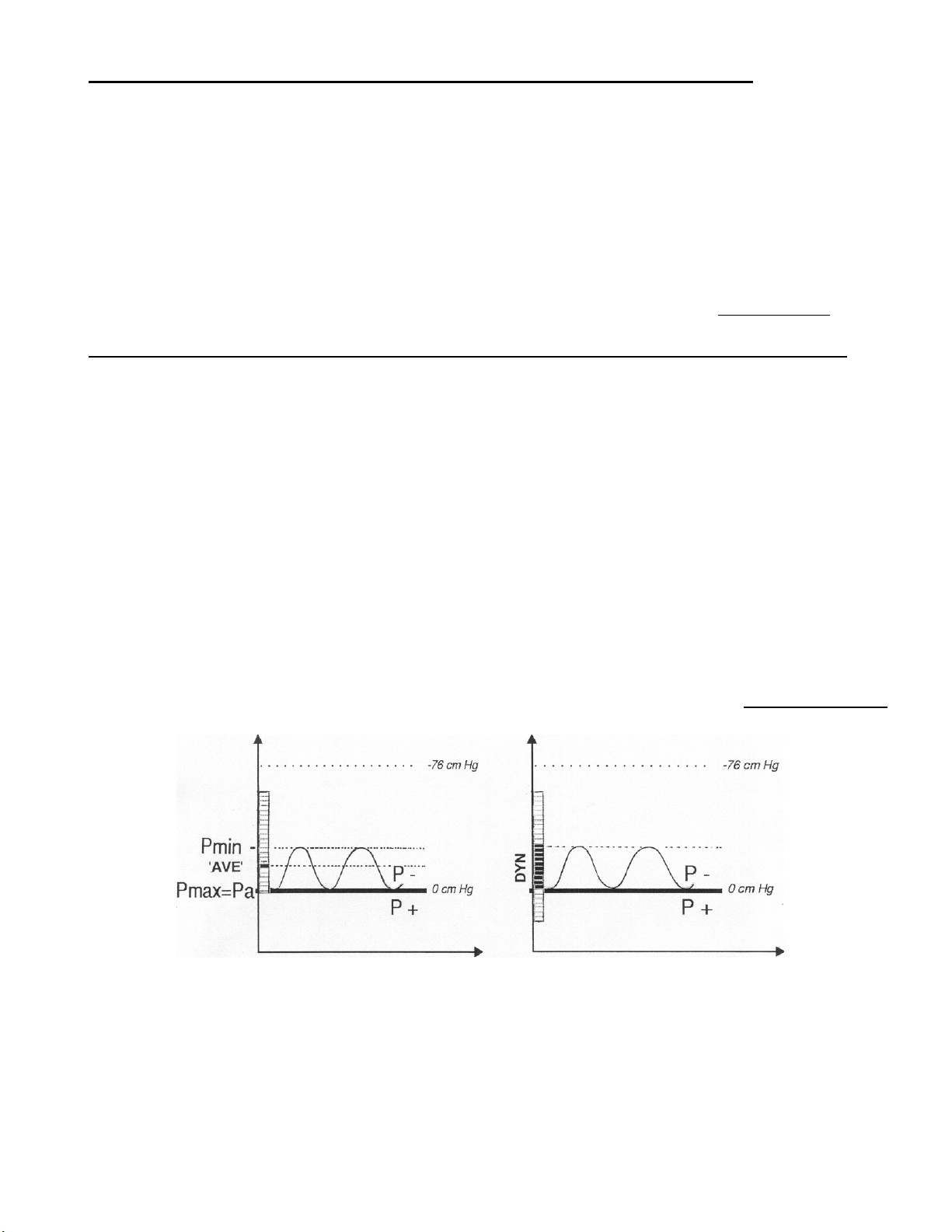
3. AVERAGE (“AVE”) & DYNAMIC (“DYN”) VACUUM MEASUREMENT MODES.
The pressure in the intake system of an engine is not constant, as it is caused by piston movement
which causes the vacuum to oscillate between a minimum and maximum level in the form of a wave,
called the vacuum waveform. Mechanical (& some other electronic) vacuum gauges display only the
AVERAGE value (“AVE”) of the vacuum waveform. This is the parameter used for the synchronisation
of throttle valves on carburettors or injection systems. However such instruments lack the speed &
precision needed to follow DYNAMICALLY the very fast fluctuations of the vacuum waveforms
themselves so as to monitor the heights and relative positions of the crests and troughs of the
waveforms of each cylinder. And it is only by monitoring and displaying these DYNAMIC
characteristics that one can reveal the existence and nature of engine seal defects which will distort &
thwart attempts at synchronisation.
The VacuumMate’s electronics & LED bar-graph displays react extremely fast, fast enough to show in
DYNAMIC (“DYN”) mode the vacuum waveform heights and relative positions for each connected
channel. This is displayed as a column of light on each LED display channel, extending between the
crests and troughs of the waveforms. By comparing the relative heights and positions of the columns
of light for each channel one can detect various problems which would normally require disassembly
and detailed investigation of engine components such as valves & pistons. See § 8. DIAGNOSTICS
below.
AVERAGE (“AVE”) & DYNAMIC (“DYN”) VACUUM DISPLAY MODES COMPARED
Use the AVE / DYN selector switch (#10, illustration, inside front cover) to select AVE or DYN mode as
required. In AVE mode the VacuumMate measures average vacuum in 3 ranges : 5-25 / 20-40 / 3555 cm Hg, selected by the 3-position selector switch (#9, illustration, inside front cover). The
overlapping scale ranges help to avoid “losing sight” of the display on one or other channel if the
measured values are somewhat out of synchronisation and close to the end of the scale range.
Resolution is a precise 0,5 cm Hg on all scales.
2
Page 3
Use the DYN mode to check for and analyse defective engine seals in case of apparent difficulty in
terna
W
V
arriving at a satisfactory synchronisation, even after several attempts and probably associated with an
irregular engine rhythm. The function of the DYN mode is to compare the waveform heights
connected channel (cylinder) and the relative positions of their crests & troughs
similar for each channel. The precise values themselves
details on using the “DYN” mode, refer to page 7, section §8. DIAGNOSTICS.
are not relevant to this purpose. For more
, which should be
of each
4. ENGINE SPEED, RPM (Revolutions Per Minute)
In RPM mode the VacuumMate monitors the waveform pulses from the pneumatic engine
connections, so no other pick-up or probe is required. As the waveform pulses are not subject to
interference or other HT parasitic stray signals they provide a much easier and more reliable signal
input than other methods. The RPM function receives it’s signal input from the waveform pulses from
the #1 channel hose connection, so it is important to connect this hose in cases where not all four hose
connections are made.
The RPM function is selected by the RPM/VAC selector switch (#8, illustration, inside front cover).
For many Japanese motorcycles and some other engines, adjustment of the engine speed to within
about 50 RPM of the correct value (as stipulated by the constructor) is essential for precise intake
synchronisation. Vehicle tachometers are usually imprecise at low-end engine speeds and should not
be used for setting or monitoring engine speed for synchronising purposes. This is therefore a vital
feature of the VacuumMate. The engine speed should be re-adjusted accurately to the correct idling
speed on completion of the synchronising task.
The RPM mode displays engine speeds from 500 to 2500 rpm, with 50 rpm resolution. The 2-stroke /
4-stroke selector switch (#11, illustration, inside front cover) allows correctly displayed values for both
types of engine. Incorrect selection will display either double the true RPM (4-stroke selected for 2stroke) or half of it (2-stroke selected for 4-stroke).
5. POWERING THE VACUUMMATE
The VacuumMate (standard model, ref VMR6WS) requires a 12Vdc external power source such as a
charged 12V battery with a capacity of at least 4Ah. To connect to this, a cord-set with alligator clips is
included in the VacuumMate kit. (Replace this immediately in case of damage or wear, see § 9.
SERVICE). Alternatively, use a well-regulated DC power supply with a power rating of at least 20W
and delivering between 11Vdc & 15Vdc. NOTE : Use only a DC power supply which you have
ensured is correctly rectified, filtered and regulated. To do otherwise may damage the VacuumMate
circuitry & invalidate the warranty. If using a 12 Volt vehicle battery make sure it is in good condition. A
battery in poor condition or a bad connection can give rise to unstable power conditions such as
voltage spikes that may damage the VacuumMate.
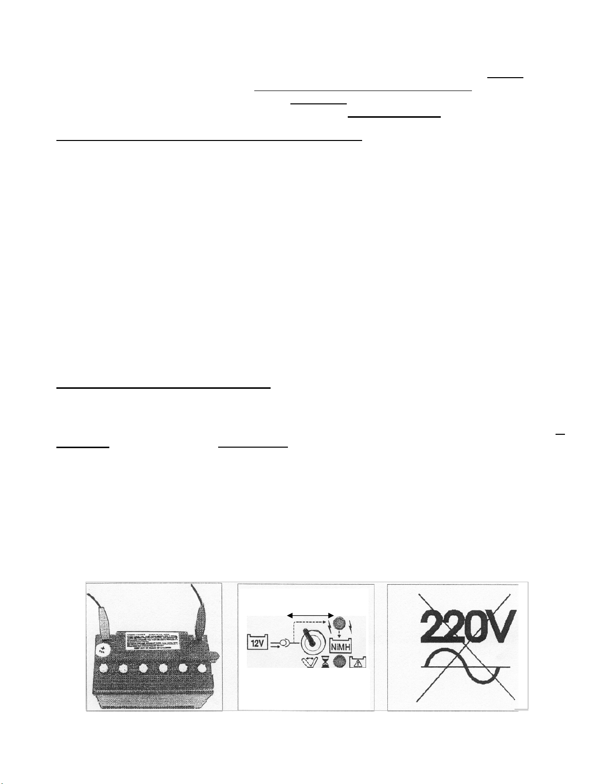
The VMR6ME model has internal rechargeable 7,2V NiMH batteries. These can be recharged when
necessary by connecting an external well charged 12V battery or regulated 12Vdc power supply using
the connection cable set supplied. The external source can also be used to power the VMR6ME, but
NOT, for safety reasons, when used on boats. On shore, whenever an external battery or 12Vdc
power source is to be connected to power the VMR6ME or for recharging the internal batteries, place
.
BATTERY SELECTION
Ex
l 12V Internal NiMH
LO
BATTERY
MR6ME LED
the battery selection switch in the 12V position before connecting and leave it so until the task or
recharging is completed, then disconnect.
3
Page 4
A well charged external 12V battery or power supply can be left connected to the model VMR6ME
when not in use to ensure that the internal batteries are always charged up. To connect the external
battery, (for VMR6ME, first place the battery selection switch in the 12V battery position), connect the
red alligator clip to the positive terminal and then the black clip to the negative terminal of a charged
12V battery. Then plug the cable set into the VacuumMate (between the rubber hoses). If the input
voltage is below 9Vdc or above 15Vdc or if the connections are incorrect (inverted), the VacuumMate
will not function. The Low Battery warning LED (see panel at the bottom of the previous page), will
indicate if the battery or power supply voltage drops below 7V and the LED bars of the display will go
into “dimmed” mode until the voltage level is again satisfactory. Note that when powered up, the LED
bars of the display will go automatically into “dimmed” mode in periods of inactivity to conserve energy,
automatically reverting to “bright mode” immediately on resumption of active measurements. When
working on internal battery power, the model VMR6ME will automatically switch itself off after 5
minutes of inactivity to conserve the battery. To re-start, move the switch to the left, then right again.
CAUTION!
even cause electric shocks! Connect ONLY to a 12V battery or suitable regulated power supply.
6. PNEUMATIC CONNECTIONS
To function correctly and give true readings all of the VacuumMate’s hoses & connections must be
absolutely air-tight
engine. Protect the hoses and connection elements from physical damage & stress and before
synchronising conduct visual & pneumatic checks to ensure there are no defects such as holes or cuts
in the hoses.
For ease of replacement the hoses are fitted to external nipples protruding from the enclosure. The
VacuumMate hoses are oil & fuel resistant and any replacement hoses should be of a similar
specification. You are advised to replace hoses only with original VacuumMate replacement hoses,
available individually, order reference VMHOSE (see § 9. SERVICE
The SERVICE MANUAL of the engine manufacturer should indicate where to make the necessary
hose connections on the engine to measure the intake vacuum. In some cases, the rubber hoses can
be fitted directly onto the vacuum connection ports (or nipples) at the manifold once the clips and
rubber sealing plugs are removed. Most engines, however, have vacuum connections plugged with
screws. Connect a rubber tube directly to each 'male' vacuum port (after removing the rubber plug) or
use the VacuumMate’s threaded adapters in case of a threaded vacuum port, after removing the
sealing screws. Connection of the channel 1 hose is essential for correct functioning of the displays.
Connection to an alternating current (AC) input will damage the VacuumMate and may
, including the connections to the adapters and at the connection points on the
).
The VacuumMate comes with unique and versatile connection adapters. The "flexi-rigid" guide tubes
can be bent slightly. They act as a guide for the plastic tubes within them, which can be rotated for
tightening the thread. This helps to make connections even where the points are hard to reach*.
Reverse thread construction at the junction of the plastic tubes & their threaded metal end pieces allow
the unscrewing of the adapters from hot engines without the risk of the metal pieces sticking in the
threaded ports. There are 4 adapters with M5 thread (Honda & Suzuki) & 4 with M6 thread (Kawasaki
& Yamaha). When the adapters are in place, insert the plastic adapter pipe(s) firmly into the rubber
hose(s) of the VacuumMate. Some silicone oil (not engine oil
• * A useful accessory kit is available, comprising a set of connection aids which are fixed permanently
to the threaded female points on the intake manifold, and terminate in readily accessible metal
nipples sealed off with rubber caps which (on removal) allow the VacuumMate’s rubber hoses to be
pushed directly onto the nipples. These kits are available with M5 & M6 threads with 40 cm of
) may help if this seems difficult.
Page 5

rubber hose (respective order references VMLFIXADP5 & VMLFIXADP6) or in short configuration
without hose, (order reference VMSFIXADP5 or VMSFIXADP6).
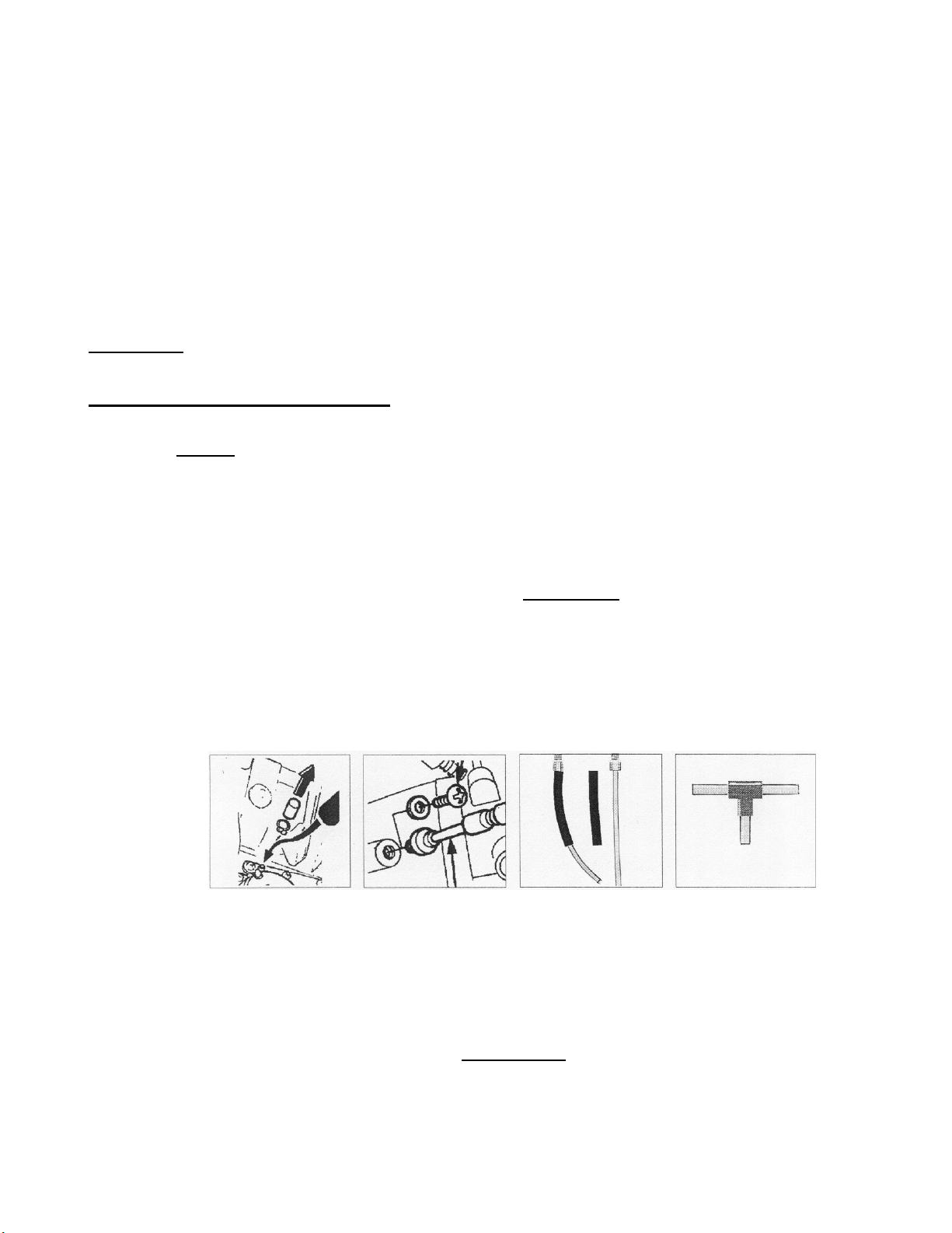
When the fuel is supplied through an automatic fuel valve, it is usually connected to one of the
vacuum ports. By using the Tee-piece (illustrated above) & it’s short piece of hose, included with the
VacuumMate, the fuel valve can remain connected, so that fuel can flow while synchronising.
Another possibility is to use a vacuum hand pump to keep fuel flowing (illustrated above, the MityVac
#4000, available from VacuumMate distributors). The advantage in this case is that there is no
influence of the
fuel valve on the vacuum readings.
7. HOW TO PROCEED
To start
Make the necessary pneumatic connections. It is best to connect the channel 1 hose first. Start the
engine and let it warm up. Connect the VMR6WS to a suitable battery or dc electrical input. If using
the VMR6ME model: move the battery selector switch lever from left to right to reset it to “ON”, as it
has an auto-switch-off feature which switches off the VacuumMate when there has been no “activity”
for 5 minutes to protect it’s rechargeable internal batteries.
5
.
Page 6

Adjust the engine speed
Select AVE mode with the AVE/DYN selector switch. Put the RPM/VAC switch in the RPM position.
RPM selection is indicated by the LED below the RPM scale markings. Position the 2-stroke/4-stroke
selector according to engine type. The left scale ("CHANNEL 1") can now be used to monitor engine
speed from 500-2500 rpm with a scale resolution of 50 rpm per individual LED segment.
Adjust the engine speed to the rpm specified by the engine manufacturer for intake synchronisation.
Re-adjust to maintain the specified rpm if necessary during the synchronisation procedure. When the
synchronising task has been satisfactorily completed, return to the RPM mode to reset the engine
speed if necessary to the correct specified idling speed.
Synchronising
One of the carburettors is called the "base" or "fixed" carburettor, sometimes the reference
carburettor. This is the carb actuated directly by the throttle mechanism (cable or rod). It is best to
connect the rubber hose of channel 1 to this “fixed” carb for convenience in synchronising the others
to it. The other throttle valves are linked to the fixed carb. Study the linkage to understand in which
sequence synchronisation is possible without influencing previously set carburettors. See illustration
below left. There is one adjusting screw for each carburettor to be synchronised. See illustration
below right.
Usually you should start adjusting the carburettor next to the fixed one. The object is to achieve the
same reading on each of the channels during idling unless the values specified for a particular engine
are slightly different for specific cylinder-manifolds. (Some examples of such engines : 4-stroke
Mercury and Yamaha outboard motors, Honda’s VFR800 motorcycle engine). Start with the scale
range switch in the position 5-25 cm Hg. If necessary shift to the 20-40 cm Hg scale. The upper scale
range 35-55 cm Hg is only required for a very few motorcycle models. The scale selection is indicated
by the LED below the respective scale markings.
For some engines synchronisation to within 0,5 cm Hg is required, but for many engines, a
synchronisation to within 1 cm Hg is adequate, so always consult the service manual to check the
required degree of precision of the synchronisation before struggling to achieve a more precise result.
Flick over to the RPM display periodically while synchronising to check that the engine RPM has not
wandered off the setting, in which case readjust to the correct RPM before continuing.
In case of apparent difficulty in arriving at a satisfactory synchronisation even after several attempts,
for example if the LED displays indicate a synchronised engine but the engine sounds irregular,
select the DYN mode to check for and analyse defective engine seals. DYN mode selection is
indicated by the LED next to the “Pa” to the right side of channel 4 display. See § 8. DIAGNOSTICS
below. Refer also to the VacuumMate “3-in-1” wall poster for a quick reminder.
6
Page 7

Finishing the job
Once a satisfactory synchronisation has been achieved, switch over once again to the RPM function
and reset the engine idling speed as required. Switch off the engine, disconnect the VacuumMate’s
electrical input from the source and from the enclosure, and disconnect the pneumatic engine
connections taking care not to burn your fingers ! The connection adapters and other accessories
are best kept for safe-keeping together with the VacuumMate itself either in the custom travel case
or, if you have a StandMate (see page 5), in the compartmentalised steel tray and instrument holder.
8. DIAGNOSTICS : HOW TO USE THE “DYN” DYNAMIC MODE
IMPORTANT: If you have not yet read section 3. “AVE & DYN VACUUM MEASUREMENT
MODES”, please do so before reading the following section.
By monitoring and displaying the DYNAMIC intake vacuum waveform characteristics one can reveal
the existence and nature of engine seal defects which distort & thwart attempts at synchronisation. In
case of difficulty in arriving at a satisfactory synchronisation, even after several attempts, (in which
case you may also have noticed an irregular engine rhythm), select the DYN mode (but only after
trying as best you can to synchronise in AVE mode).
Some engine seal defects quickly diagnosed in DYN mode are Leaking intake or exhaust valves
'False' air entering the intake system
Compression loss….
Background information
The diagrams below show some more realistic examples of pressure waveforms which can occur in
the intake manifold of a 4-stroke engine. Compare with the drawings on page 2.
The pressure scale orientation has been deliberately inverted so as to rather show vacuum scale so
as to correlate with the LED displays of the VacuumMate.
The display appears as a shimmering column of light. In reality a single LED on each connected
display channel follows the wave-form curve (from left to right) at great speed rather like a very fast
roller-coaster car, tracing the vacuum wave-form between troughs and crests. Because the speed of
observation of the human eye cannot match that of the running engine’s vacuum wave-form your eye
sees the resulting display as a column of light of height and position equating to the troughs and
crests.
NORMAL INTAKE
VACUUM WAVE-FORM
– ENGINE SEALS O.K.
The LED-column
display illustrated with
a typical intake
pressure wave-form
During the intake stroke
the intake valve is open
and the piston moves
down, increasing the
vacuum until the crest of
the vacuum wave-form
(inverted pressure waveform) is attained.
When the intake valve closes, suction ceases and the mixture coming through the throttle valve fills
up the vacuum, so that the vacuum is “released” to atmospheric pressure (Pa mark) at the trough of
the vacuum wave-form. The slight apparent “over-shooting” of the Pa mark datum can be thought of
as due to “shock” effect.
7
Page 8

In DYN mode the waveform heights of each connected channel (cylinder) and the relative positions of
their crests & troughs are displayed side by side for direct comparison.
When all carburettors have been correctly synchronized and everything works normally, the bands
should all have the same height and position. (See illustration below left and comment** below).
** Note that this statement is not precisely true of certain engines for example that of the Honda
VFR800 motorcycle and certain Mercury, Mariner & Yamaha 4-stroke outboard motors on which
certain cylinders have slightly different “AVE” intake vacuum setting values by design.
☺
The VacuumMate has an auto-ranging feature in DYN mode. The range is automatically adjusted to
achieve optimal resolution for the comparison of the connected channels. The channel with the
highest waveform crest governs the auto-ranging adjustment. The bases of the displayed columns of
light for engines without defective seals should normally be almost exactly opposite the “Pa” mark (Pa
= Atmospheric pressure) on the right hand side of the LED displays (see above left). Other than the
Pa mark there are no scale markings for the DYN mode as the purpose is not to measure but rather
to compare
the Pa level) means POSITIVE pressure (higher than atmospheric), upwards into the P- zone means
vacuum.
Some abnormal display patterns are shown above, centre and right. The nature of the waveform
anomaly reveals the nature of the engine sealing defect because various different defects give rise to
different patterns of waveform anomaly. The most common anomalous wave-forms are shown on
the next page.
EXAMPLE 1 :
EXHAUST VALVE NOT CLOSING
When one of the exhaust valves is not closing completely, a part of the exhaust gas will be “sucked
back” into the combustion chamber during the intake stroke. This is evident from the “DYN” mode
LED column displayed for that cylinder, whose highest point (crest of the vacuum wave-form) will be
lower than on the other (normal) channels.
FALSE AIR INTAKE
'False air’ is air which is sucked into the cylinder after the throttle valve. For example in case of a leak
in the intake manifold. The display in DYN mode looks very similar to that of a leaking exhaust valve.
The highest point of the LED column displayed for that cylinder will also be lower than on the other
channels.
A typical anomalous wave-form for these defects is illustrated on the next page.
8
100% NORMAL EXHAUST VALVE INTAKE VALVE
the connected channels. A light column extending downwards into the P+ zone (below
Page 9

EXAMPLE 1 : LEAK THROUGH EXHAUST VALVE OR INTAKE
MANIFOLD
The normal wave-form is shown in paler tone for comparison with the darker abnormal wave-form.
EXAMPLE 2.
INTAKE VALVE NOT CLOSING
If one of the intake valves is not closing completely, it means that the combustion chamber is
continuously connected with the intake system. During the combustion cycle, a high pressure wave
will 'blow back' to the carburettor creating positive pressure in the intake manifold. The trough of the
vacuum wave-form (the low point of the displayed dynamic band of that cylinder), will move under the
Pa line towards the P+ side, reflecting this positive pressure.
EXAMPLE 2 : LEAKING INTAKE VALVE
The normal wave-form is shown in paler tone for comparison with the darker abnormal wave-form.
9
Page 10

9. SERVICE
0
Accidental immersion
In case of accidental immersion in water retrieve the VacuumMate immediately and disconnect from
any electrical input. Dry off the VacuumMate and blow out the DC power inlet using a hair dryer.
Carefully remove the soft rubber sealing plug covering the calibration trimmers at the lower end of the
VacuumMate and blow out the
calibration cavity with a hair dryer.
If there is evidence of water inside the unit, shake
out as much water as possible through the calibration aperture,then dry
thoroughly using a hair dryer, then place against a vertical surface with calibration cover at the top
and allow to dry out completely. Replace the calibration cover only when you are sure all humidity
has been removed , taking care that it is well seated as this is essential to minimise damage in case
of a future accidental immersion. Entry of water, especially salt water, will cause damage unless
completely and immediately removed. Connect again to electrical power only once you are
absolutely sure there is no water inside the unit or in or around the DC power inlet.
In case of malfunction following immersion please return to your distributor for checking and repair.
Damage to plug
may impair water
Calibration
This instrument has been carefully checked and calibrated at the factory, and in normal use
calibrates itself automatically against day to day changes in barometric pressure. However, after a
time, gradual “drift” of the pressure sensor calibrations, together with the accumulated effects of
handling knocks, wear and tear and severe temperature changes, will require correction of the
calibration.
WHEN TO CALIBRATE?
Connect the instrument to power and allow it to warm up for at least 5 minutes. Then check the
position of the 4 LEDs in DYN mode with the rubber hoses open to the air (i.e. not connected to the
engine). All the LEDs should be aligned with the Pa line for perfect calibration. However, if the LEDs
are within one graduation up or down from the Pa line and within one graduation of each other,
calibration is not essential. Otherwise, calibration is necessary. Proceed as follows below.
Perfect calibration : do not recalibrate
Examples of display when calibration is not essential
Examples of display when calibration is necessary
10
Pa
Pa
Pa Pa
Pa
1
Page 11

HOW TO CALIBRATE - PREPARATION
The following equipment is required to
successfully recalibrate the
VacuumMate:
• A hand operated vacuum
pump with a built in dial calibrated in kPa,
mBar or cm Hg (e.g. MityVac # 4000), or
a hand operated vacuum pump with
external in-line vacuum guage of
equivalent accuracy.
• A one into four divider
which allows all four channels of the
VacuumMate to be connected to the hand
operated vacuum pump. See page 12, ref.
VM1TO4DIV for this optional accessory.
• A FLAT instrument screw
driver with a shaft diameter of 2,2 - 3mm.
See page 12, ref. “VMCALKIT”.
To reach the calibration trimmers,
carefully remove the soft rubber sealing plug at the lower end of the VacuumMate. You will now see
12 (VMR6ME model) or 11 (VMR6WS model) trimmer- potentiometers.
Adjust ONLY the 8 trimmers grouped in 4 pairs on the right.
Do NOT adjust the other trimmers.
ADJUST ONLY THESE TRIMMERS
The calibration trimmer positions are marked on the lower edge
of the control panel.
Damage to plug
may reduce water
resistance
HOW TO CALIBRATE – PROCEDURE
Select “VAC”, 35-55 cm Hg and AVE with the switches on the control panel. Create a vacuum of
–70kPa / 700mBar / 52,5cmHg with the hand operated vacuum pump. Adjust the SPAN trimmers
until 52,5cmHg of vacuum is displayed on all 4
channels. Release the vacuum completely by
disconnecting at least one tube from the 1 into 4
divider. Select DYN with the AVE/DYN switch
on the VacuumMate control panel. Adjust the
Pa trimmers until all four channels display on the
Pa pressure line exactly opposite the Pa mark.
Pa SPAN
Pa SPAN
Pa SPAN
Pa SPAN
REPEAT THE WHOLE PROCEDURE at least once to recheck your adjustments.
NOTE: In case of calibration or other difficulties, go to www.tecmate-int.com
, click on “VacuumMate”
for more details or on “Contact Us” then “Technical Questions” or “Service & Repairs” for further
assistance.
11
11
Page 12

Replacement spare parts
Some components may need replacing after some time in case of damage, wear and tear or loss.
Do not use the VacuumMate in case of worn or damaged pneumatic connections, hoses or adapters.
Never use a damaged or worn battery cord-set, as this may cause anomalous electrical spikes which
may badly damage the VacuumMate.
Please quote the article order reference as stated below when re-ordering parts or accessories from
your VacuumMate distributor.
ORDER REFERENCE
VMHOSESET Rubber hoses, set of 4.
IMBATCORD External battery connection cord-set with clamps.
VMCALKIT Miniature screwdriver, replacement calibration hatch sealing cover.
VMR6MHOLSTER Rubber holster, yellow, VacuumMate Allweather.
VMR6MBAT NiMH battery pack for VMR6ME model.
VMM5ADPFRSET Set of 4 “flexi-rigid” connection adapters with M5 thread.
VMM6ADPFRSET Set of 4 “flexi-rigid” connection adapters with M6 thread.
VMR6MECASE Travel case with decal , rechargeable model VMR6ME.
VMR6WSCASE Travel case with decal , non-rechargeable model VMR6WS.
VMTEESET Tee-connector and 10 cm length of connection hose.
VMR6POSTER Wall poster “3-in-1”.
VMR6MANGB User manual, English text.
DESCRIPTION
Accessory Items
IMSTAND StandMate in easily assembled complete kit.
IMSTATANK Suspendable auxiliary fuel reservoir for use with StandMate.
MV4000 MityVac #4000 hand vacuum pump kit with adapters & storage case.
VM1TO4DIV One into four divider connection special accessory for calibrating.
VMLFIXADP5 Permanent “E-Z-fix” connection adapter with 40 cm hose, M5 thread.
VMLFIXADP6 Permanent “E-Z-fix” connection adapter with 40 cm hose, M6 thread.
VMSFIXADP5 Permanent “E-Z-fix” connection adapter without hose, M5 thread.
VMSFIXADP6 Permanent “E-Z-fix” connection adapter without hose, M6 thread.
Limited Warranty
VacuumMate is guaranteed against defects in manufacture and component parts for 12 months from
date of sale to the user. The manufacturer reserves the right to require presentation of the original
invoice or bill of sale to the user as proof of a valid warranty. Failure to observe the instructions
contained in this user manual invalidates the warranty. Physical or chemical damage or damage
resulting from corrosion or immersion, to cord-sets, hoses, connection adapters, or to the instrument
itself, are not covered by this limited warranty. The travel case is excluded from the warranty.
In the event of a claim the owner must return the VacuumMate carriage paid to the distributor after
first contacting the distributor to advise him/her. Repairs to or replacement of defective VacuumMates
will be effected at the sole discretion of the manufacturer or his duly authorised distributor.
All consequential damages or liabilities arising from or claimed to arise from the use or misuse of the
VacuumMate or any accessory are expressly excluded from this limited warranty which is the sole
warranty recognised by the manufacturer TecMate (International) S.A. or his authorised distributors.
Service: www.tecmate-int.com
, click on “Contact Us” and go to “Repairs”.
12
 Loading...