

Page 1
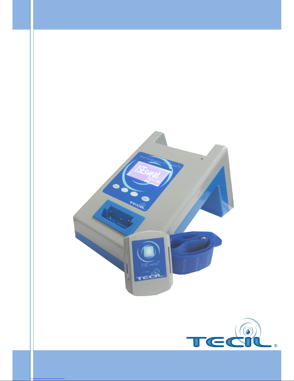
ISEsweat II
®
Sweat Chloride Analyzer
User’s manual
V00EVP012014
Page 2

Page 3

INDEX
1. INTRODUCTION ........................................................................................................................ 5
1.1 ISEsweat intended use............................................................................................ 6
1.2 Operating principles ............................................................................................... 6
1.3 How to use this manual .......................................................................................... 7
2. DEVICE DESCRIPTION ............................................................................................................. 8
2.1 ISEsweat ................................................................................................................ 9
2.2 Terminal or receiver base ..................................................................................... 10
2.3
Remote module ................................................................................................... 11
2.4 SENSOR CARDS ..................................................................................................... 12
3. ISESWEAT INSTALLATION ................................................................................................. 13
3.1 Components ......................................................................................................... 14
3.2 Power source connection ..................................................................................... 14
3.3 Battery ................................................................................................................. 16
4. SWEAT ANALYSIS .................................................................................................................. 19
4.1 Settings ................................................................................................................ 20
4.2 Sweat induction and analysis ................................................................................ 22
4.3 Interpreting of sweat test results .......................................................................... 27
4.4 Calibration and control ......................................................................................... 27
4.5 Quality Control Mode (QC)-ISEtrol N and ISEtrol A ................................................ 28
5. DATA PORT USE..................................................................................................................... 30
5.1 General summary ................................................................................................. 31
5.2 Data port connection............................................................................................ 31
5.3 Print Data ............................................................................................................. 31
5.4 Memory ............................................................................................................... 33
6. MAINTENANCE ....................................................................................................................... 35
6.1 Technical service .................................................................................................. 36
6.2 Periodic security check ......................................................................................... 36
6.3 Cleaning ............................................................................................................... 36
6.4 Waste management ............................................................................................. 37
Page 4

ANNEX A: TROUBLESHOOTING TABLE ................................................................................... 38
ANNEX B PRODUCT SPECIFICATIONS ..................................................................................... 40
ANNEX C POSSIBLE INTERFERENCE ........................................................................................ 43
ANNEX D RECOMMENDATIONS FOR THE RESULTS INTERPRETATION ...................... 45
ANNEX E SYMBOL DEFINITIONS ............................................................................................... 47
ANNEX F REGULATIONS ............................................................................................................... 50
ANNEX G MANUFACTURER DECLARATION ........................................................................... 53
ANNEX H WARRANTY ................................................................................................................... 56
ANNEX I HISTORY SWEAT TEST ................................................................................................ 58
ANNEX J REFERENCE ..................................................................................................................... 60
Page 5

1. INTRODUCTION
Page 6
ISEsweat
- User’s Manual 6
1.1 ISEsweat intended use
ISEsweat is intended for quantitative pilocarpine iontophoresis sweat chloride testing for the
diagnosis of cystic fibrosis.
ISEsweat should only be used by Doctors, nurses and trained laboratory personnel. It is
highly recommended that users gain prior experience before diagnosing Cystic Fibrosis.
The place for testing may be in laboratories, hospitals or clinics
In order to increase the possibility of collecting an adequate sweat sample, it is advisable to
conduct the first chloride sweat determination tests on individuals older than 2 weeks and
weighing above 2kg.
Sweat volumes are dependant on age, sex, corporal weight, race, skin condition and
sampling system.
ISEsweat® is a Sweat Chloride Analyzer intended for Cystic Fibrosis Diagnosis.
CAUTION: ISEsweat® is intended only as a supplement in a patients’ evaluation. It must
be used in conjunction with other signs and symptoms. Don’t take any clinical decision
based only on the sweat test evaluations.
1.2 Operating principles
Cystic fibrosis is a multisystem disorder that causes formation and accumulation of dense
mucus, that affects mainly lungs, intestines, pancreas, and liver. Cystic fibrosis is also
characterized by the presence of a high chloride (Cl-) concentration in sweat, which is the
basisi of this diagnosis: (commonly known as the sweat test). This test QUANTIFIES the
chloride levels excreted while sweating, and is indicative for CF diagnosis.
The ISEsweat® runs the sweat test in two different stages: IONTOPHORESIS or sweat
stimulation and MEASUREMENT of the chloride concentration.
The first phase is called IONTOPHORESIS because sweat stimulation is done using this
technique. Its purpose is to get a sweat stimulating drug, pilocarpine, through the skin, with
the help of an electrical potential difference. Pilocarpine excites the sweat glands and
stimulates sweat on the treated area. Once there is enough sweat, the second phase begins.
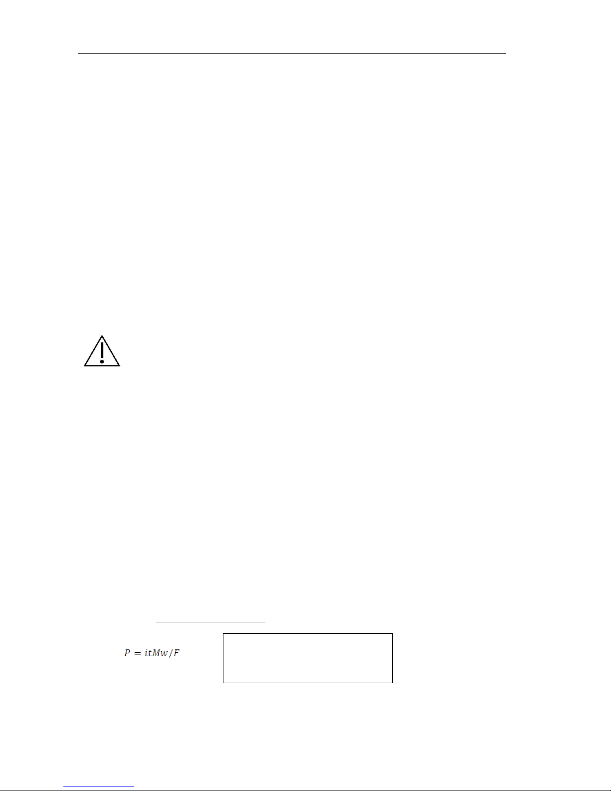
The amount of pilocarpine delivered varies directly in proportion to the current and time
according to the Faraday equation below:
The second phase is called the MEASUREMENT phase. Chloride ion (Cl-) concentration is
measured in the sweat produced by iontophoresis. The analysis is made without any need to
i Intensity in mA
t Iontophoresis time
Mw Pilocarpine molecular weight
F Faraday constant
P mg of released pilocarpine
Page 7
ISEsweat
- User’s Manual 7
manipulate the sample, using the microsensors on the Measurement side of the sensor card.
There is no need to collect the sample, it is analyzed at once, thus avoiding evaporation or
pollution problems.
Results obtained by the sensor card are transmitted by the remote module, and processed at
the ISEsweat® base, to give the chloride ion concentration. ISEsweat® uses the direct
potentiometry method, with a chloride ion selective electrode (commonly called ISE),
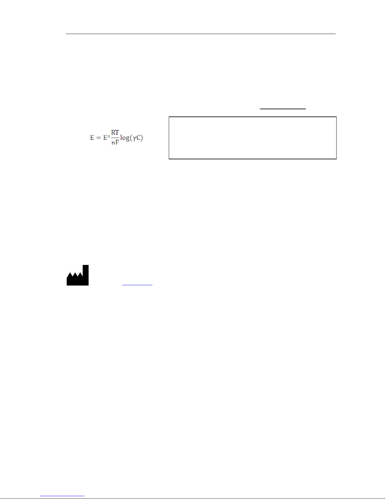
responding only to the Cl ion in the sweat. The relation between the developed voltage and
chloride ion concentration is logarithmic, and it is expressed by the Nernst equation:
The analyzer measures the electrode potentials, and the data is processed by a
microprocessor to calculate the chloride ion concentration.
1.3 How to use this manual
This user manual has been produced by Tecil in order to guarantee the correct use of the
ISEsweat® equipment. Before putting the equipment to work, please read carefully all pages
and, if you have any doubts, contact the relevant department. Only authorized Tecil agents
can translate this manual.
Information in this manual can be changed without prior warning. This product is permanently
being developed and perfected. The manufacturer keeps the right to make any modification
on the design features without prior warning.
E Potential of electrode in contact with sample
E° Potential of reference electrode
RT/nF Temperature constant
N Valency (chloride ion is 1)
Log Logarithm base 10
γ Chloride ion activity coefficient
C Analyzed ion concentration
Tecil, S.A.
Lope de Vega 99-101
08005 Barcelona (Spain)
Web: www.tecil.com
E-mail: [email protected]
Phone: + 34 902995746
Fax: + 34 933084871
Page 8

2. Device description
Page 9
ISEsweat
- User’s Manual 9
2.1 ISEsweat
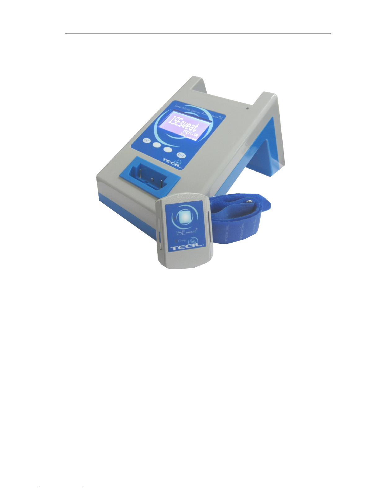
ISEsweat® is intended for use by qualified personnel to measure chloride in sweat. The
resulting concentration value of patient´s sweat is used for diagnosis of cystic fibrosis.
The current for iontophoresis was reduced to 0.4 mA, to minimize the risk of causing irritation
to the patient. After 10 minute of iontophoresis, the stimulated area is washed with distilled
water, and reverse face of sensor card is placed. After 15 minutes the concentration of
chloride directly from the skin of the patient is measured. The data is then transferred to the
base by radiofrequency ( RF) and the value of chloride is displayed in mmol/l.
The analyzer consists of 2 separate parts:
1. Terminal or receiver base, includes: an LCD screen where results of the
analysis are displayed;
2. Remote module, has just one push button on the front. This remote module has
the holder for the innovative disposable sensor card patented by Tecil which are
involved with the stimulation, sweat collection and reading the chloride
concentration obtained from the patient’s sample.
ISEsweat® uses a detachable sensor card to run each sweat test. They consist of two
different sides; each one performs a different process (IONTO side and MEASURE side).
Once the card package is opened, each sides have a different appearance, thus making it
difficult to make a mistake when choosing the appropriate side. In the event of mistake,
ISEsweat will alert you about wrong side placed !!
Page 10

ISEsweat
- User’s Manual 10
2.2 Terminal or receiver base
Receiver unit for the reception of data coming from the remote analyzer module, display and
record in the internal data base memory
Display:
Appears all the information about
the test ( phase, time remaning…)
Base LED:
It turns orange or green at the
same time as the charge led indicator on the
remote. When it’s orange is “charging” and
when is “green” is charged.
Control panel:
This four buttons helps the
user to move around the interphase on the
software’s base. Their function could change,
depending on which screen appears on the
base.
Remote module slot
:
It’s a connector to
charge the remote battery, once the base of
the remote It’s plugged in on this slot.
On/Off switch:
Turns On or Off the base of
the ISEsweat.
AC Power supply connector:
Side where
plug the power supply connector to the base
of ISEsweat.
Printer connector: Port to connect a
printer serial cable, to print the results.
USB port connector: Port to connect an
USB cable to a PC.
Control panel, to access to different
functions
Display
Base LED
Remote module slot
On/Off switch
AC Power supply
connector
Printer connector
USB port connector
Page 11
ISEsweat
- User’s Manual 11
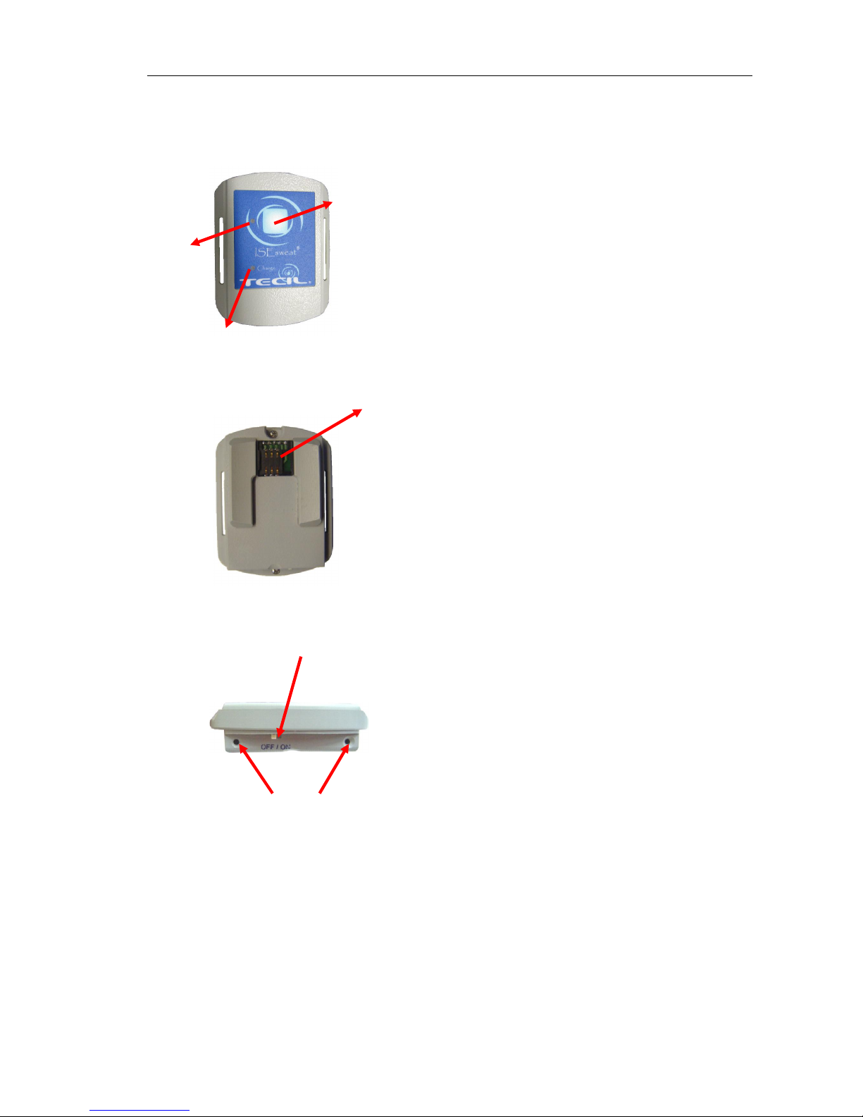
2.3 Remote module
Remote LED indicator: Indicates the
phase of sweat test, and if there’s some
problem, using a two colour LED.
Charge LED indicator: Indicates if it’s
charging (orange) or fully charged
(green).
Remote push button: Pressing this
button: starts, changes the phase and
stop the remote.
Sensor card slot: Slot where the sensor
cards are connected to run the
iontophoresis, and the measurement
phase.
On/Off switch: Turns On/Off the
Remote.
Charge contacts: Contacts where the
remote it’s plugged to the remote module
slot
Remote LED
indicator
Charge LED indicator
Remote push
button
Sensor card
slot
On/Off switch
Charge contacts
Page 12
ISEsweat
- User’s Manual 12
2.4 SENSOR CARDS
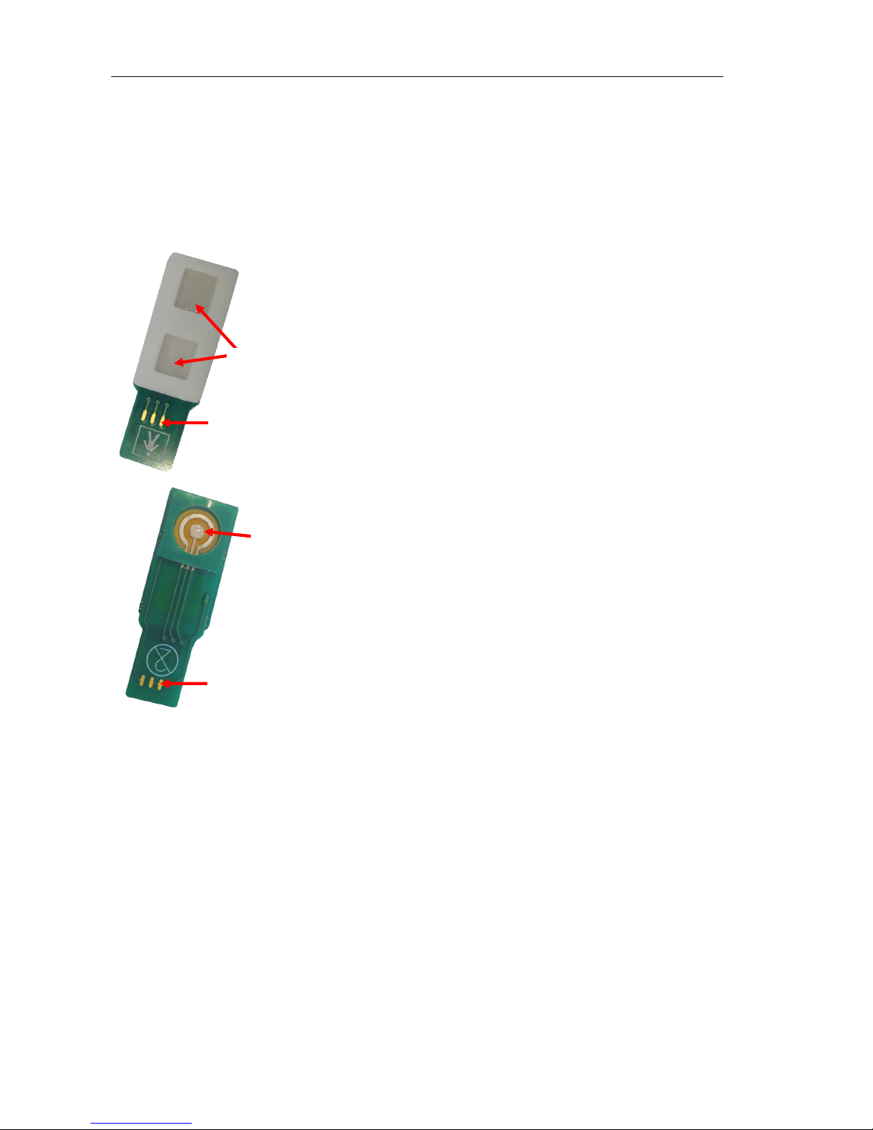
ISEsweat® uses a sensor card to run the analysis or sweat test. It consist of two different
sides; each one performs a different process (IONTO side and MEASURE side). The name
of each side alludes to its function.
Once the card package is opened, you can distinguish these two sides by the appearance,
thus making it difficult to make a mistake when choosing the approriate side.
IONTO SIDE this stimulates sweat on the
patient through two square-shaped hydrogel
iontophoresis pads containing a solution of 0.5%
pilocarpine nitrate.
MEASURE SIDE this measures the chloride
concentration (sample or control) through the ISE
technique. It consists of 2 concentric circular
electrodes, covered by a transit gel that the user
has to remove before using.
Gels
Connector
Connector
Electrodes
Page 13

3. ISEsweat installation
Page 14
ISEsweat
- User’s Manual 14
3.1 Components
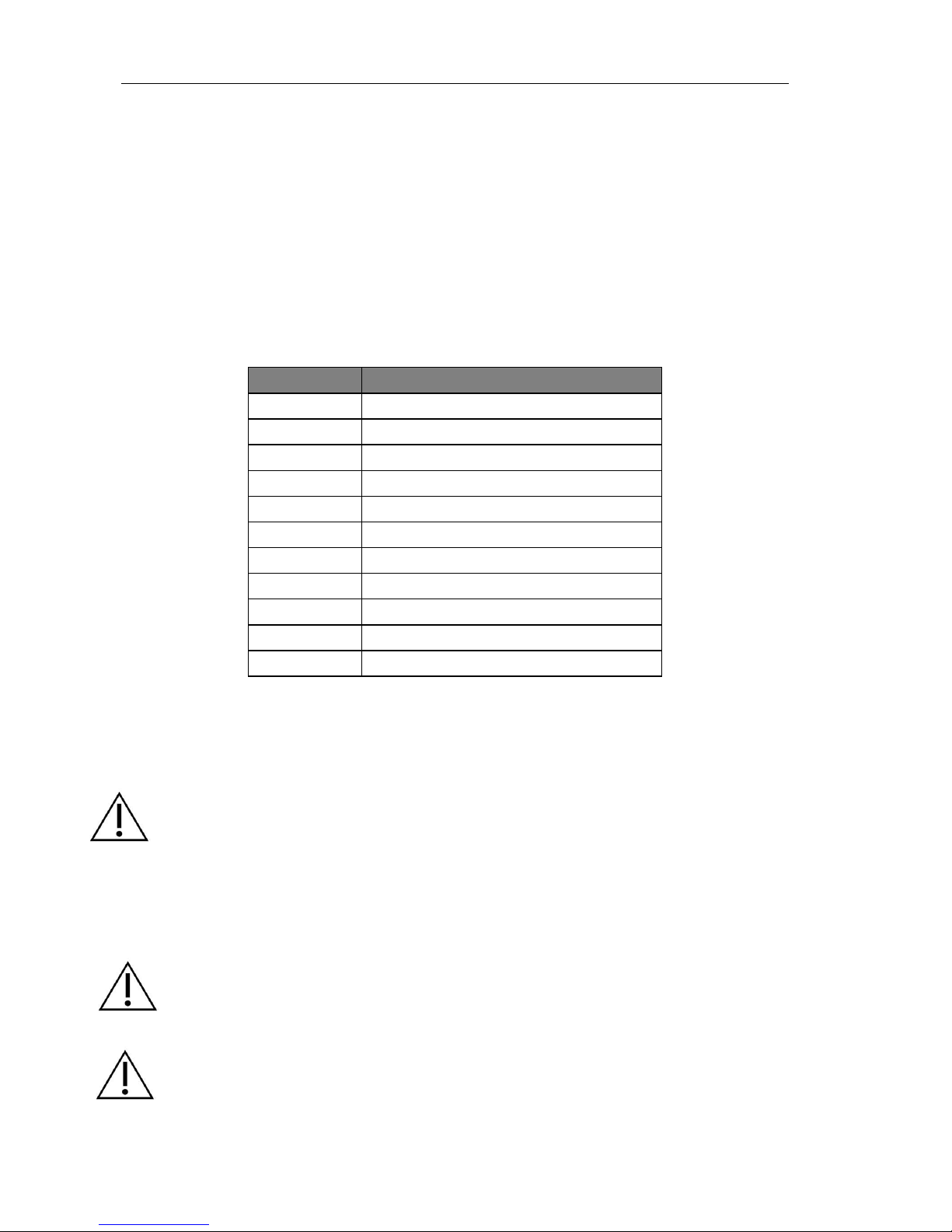
Use the list in the following table to check that you have received all needed components.
If any of the components are missing or damaged, please inform your distributor at once.
TECIL only takes responsibility for notifications received within 72 hours after product
delivery. Once notified, you have 15 days from the receipt date to effect any return.
Use only the recommended accessories. If you have any doubts, please contact your
distributor or the manufacturer.
It is recommended that you keep the packaging material in case it is needed for further
transport.
Packing List
CODE DESCRIPTION
T601
Complete ISEsweat®
T611
Receiver base
T620
Transmitter module (remote)
T700
Sensor cards
T800
Quality Control Kit
T900
DC 12v Power supply unit 1,5 A
T901
Printer Series Dock Cable – OPTIONAL
T902
USB cord - OPTIONAL
T903
Armband
TM-U220DS
Printer Series Dock - OPTIONAL
T908
Power Cord
3.2 Power source connection
WARNING: When you connect the ISEsweat, check that it works correctly before using it for
clinical purposes. The accessories connected to the ISEsweat® data interface must comply with
IEC EN 60950 regulations for data processing equipment certificate or IEC EN 60601-1
regulations for electrical medical equipment certificate. Any person that connects other
equipment to the input/output ports (ISEsweat® data port connector) is configuring medical
equipment, and as such is responsible for guaranteeing that the system follows the IEC EN
60601-1-1 and EN 60601-2 Regulations for electromagnetic compatibility. All accessories
supplied by TECIL comply with all these regulations. Connect the equipment to a power
supply with an earth connection.
WARNING: Use the equipment in dust free, mechanical vibration free and electrical
interference free areas. Avoid the proximity of brush motors (in some centrifuges), heat
sources or blinking fluorescent lights. Readings and signals could be affected.
CAUTION: DO NOT lift the ISEsweat® base by the power supply cable; it could become
disconnected and damage the ISEsweat®.
Page 15
ISEsweat
- User’s Manual 15
CAUTION: DO NOT soak the equipment in water or put it in a very high humidity area.
CAUTION: In order to guarantee patient security and that the equipment remains in good
condition, DO NOT place the ISEsweat® in any place from where it could easily fall.
CAUTION: DO NOT use the ISEsweat® in the presence of anesthetics or flammable gases to
avoid risk of explsion.
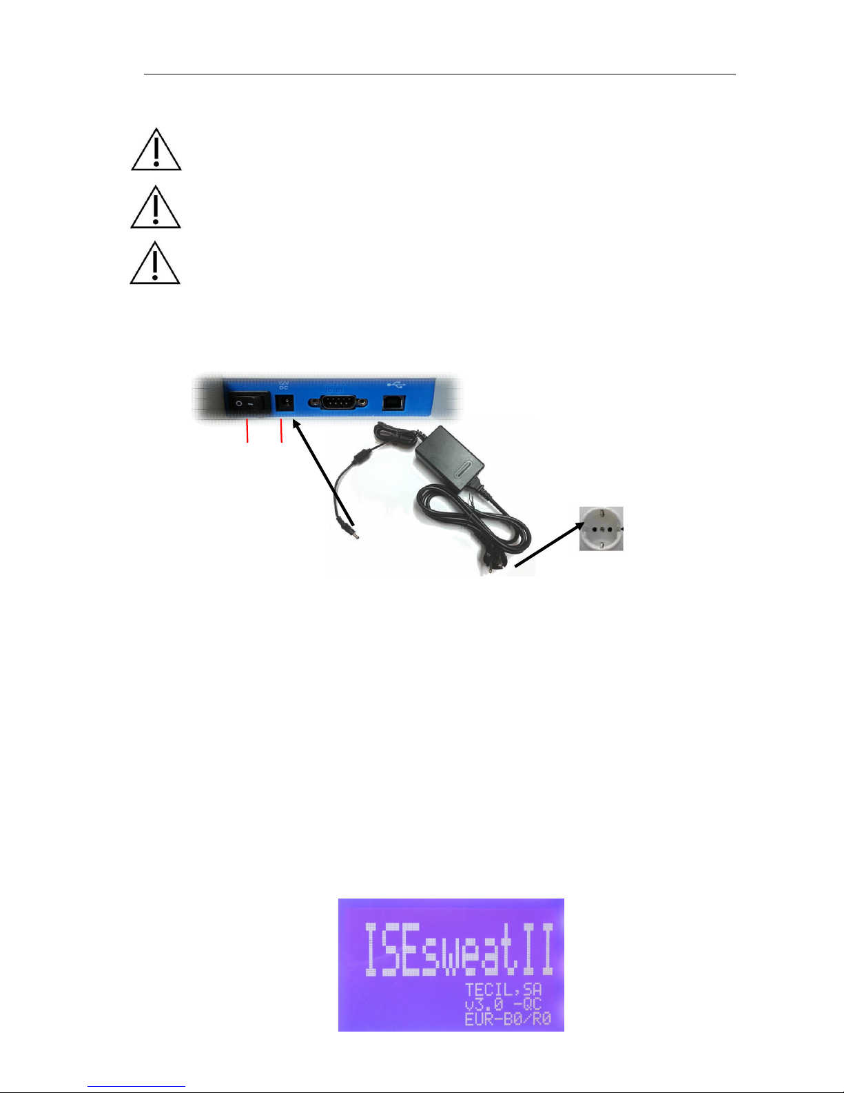
Study the figure below and follow the instructions in order to make the power supply
connection.
2 – Power supply On/Off switch
3 – AC power supply connector CA
1. Plug the power supply cord connector to the power supply connector (3).
2. Plug the power supply cord to a CA power network point with an earth connection
(Shuko type).
3. Press the power On/Off switch (— / O) (2) to the ON position (— symbol) to start up.
When connecting the equipment to the power network, please ensure that it cannot become
easily disconnected. After connecting and installing the ISEsweat®, press the power switch to
the ON position (—), to initiate the program. ISEsweat® makes an acoustic signal (1 beep)
and the base LED indicator will light (orange) and come on for a second. When the left hand
switch is turned on, the following software load screen will appear on the ISEsweat® screen
for 10 seconds.
1. Product brand
2. Company
3. Software version – Work mode
4. Work frequency – Base number / Linked remote number
2
3
1
2
3
4
Page 16

ISEsweat
- User’s Manual 16
3.3 Battery
The ISEsweat® transmitter module or remote includes a Lithium-ion (Li-ion) battery with a
650mAh capacity that allows it to work. When completely charged the battery will last for 6
hours and allow for 10 analyses.
It is highly recommended that the internal battery is replace every 2 or 3 years, depending on
the use. Batteries capacity decreases with use (see Battery replacement section).
If the ISEsweat® is not going to be used for some time, it is recommended that you get in
contact with the technical support service, and disconnect the remote using the switch on the
front side.
Recharge the battery before using if it has been inactive for 3 months or more.
WARNING: ISEsweat® remote will not work if the battery is completely flat. Please, check the
battery state before using the remote (see Battery Indicators).
Battery indicator
During use, you can check the battery charge state by referring to the symbol on the upper
left hand corner of the base screen. The battery indicator appears once the analysis has
begun.
Charged
battery
Battery at
medium/low level
Discharged
battery
WARNING: Starting an analysis with a low battery level can influence the results. It is highly
recommended that you recharge the battery level whenever it is low. Please, check that the
remote has an adequate battery charge level before running the analysis; otherwise, the
battery may discharge during the analysis. After running an analysis, plug the remote module
into the base charger slot until next analysis, to avoid getting a flat battery.
Charging process
The Battery will only recharge if ISEsweat® is connected to a CA power supply ( BASE ON
and REMOTE OFF) . Therefore, it is recommended that the ISEsweat® base is always
connected to the CA power supply, and that the remote is left in the charging slot, so the
battery is fully charged for remote use at anytime.
NOTE: Distinction between connection and operation.
Operation refers to any part of the analysis (sweat test) or quality control phases, where the
remote module is in use.
Page 17
ISEsweat
- User’s Manual 17
However, connection refers to the starting up/shutting down of the remote module
using the switch at the lower side. If the remote is shut down it won’t work; there is no
power.
To start the charging process, please follow the instructions below:
1. Interrupt the equipment operation
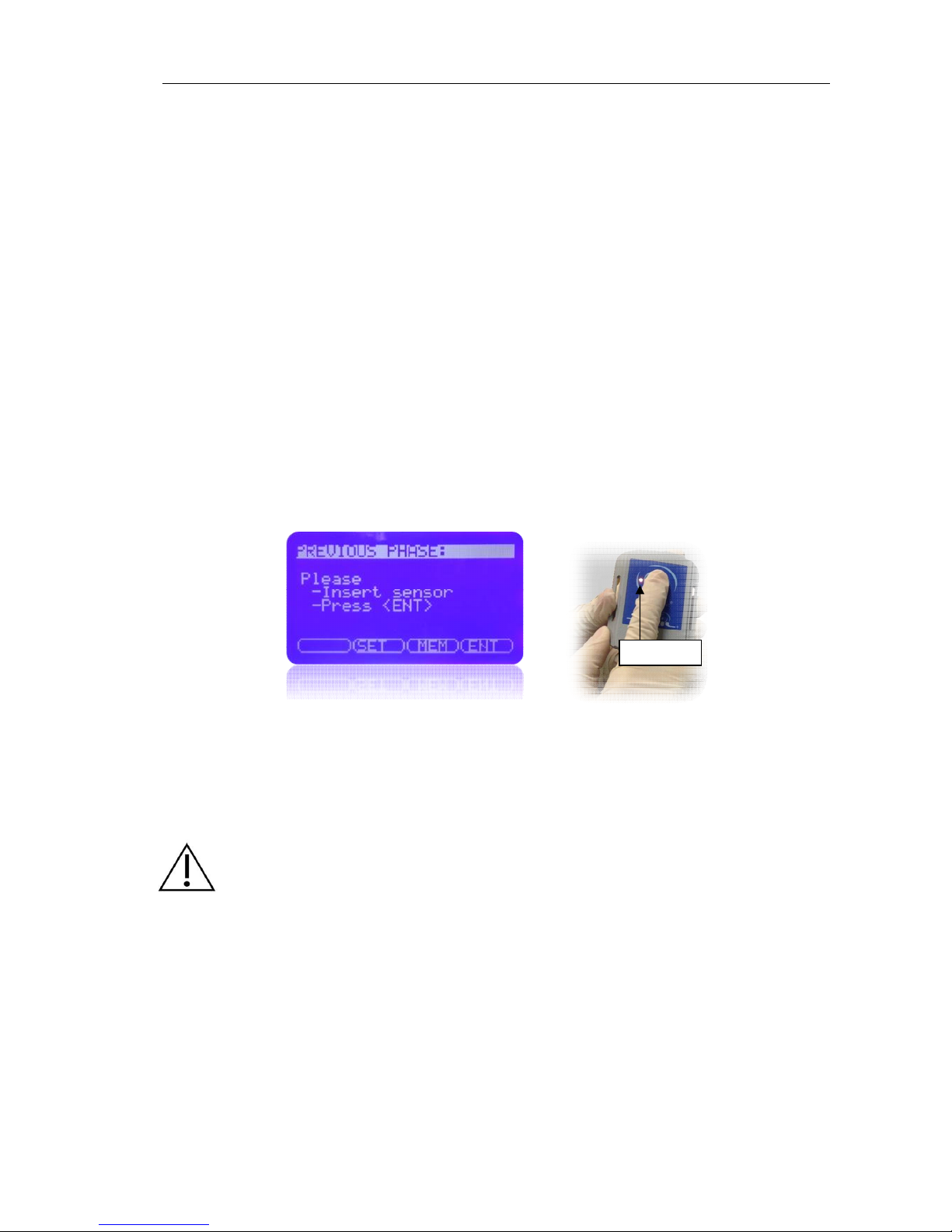
In order to start the charging process, the remote must not be operating. The screen
on the Base Unit should be showing the Start Screen or the Previous Phase, not any
of the running mode screens, (measurement, ionto, wait, etc…)
To make sure the remote is not operating:
1. Press for 4-5 seconds the remote central button, until the remote LED turns
orange.
2. Release the button when the LED color changes. The remote is now switched
off and the remote LED indicator is should be off.
2. Remote disconnection
Once the remote is not operating and before starting the charging, please disconnect the
remote completely by switching the side switch to OFF.
WARNING: During a test session you can continue to charge the equipment without
disconnecting the remote but in this case, you will not be able to check that it is fully charged
(green LED) because of the power the remote is consuming. After ending the test session,
please disconnect the equipment and put the remote in the charging position, as described
above, to achieve a full charge.
3. Charging
To charge the battery, put the remote in the charge slot on the ISEsweat® base unit, as
shown in the following figure.,The estimated time to achieve a full battery charge is around
6 or 7 hours.
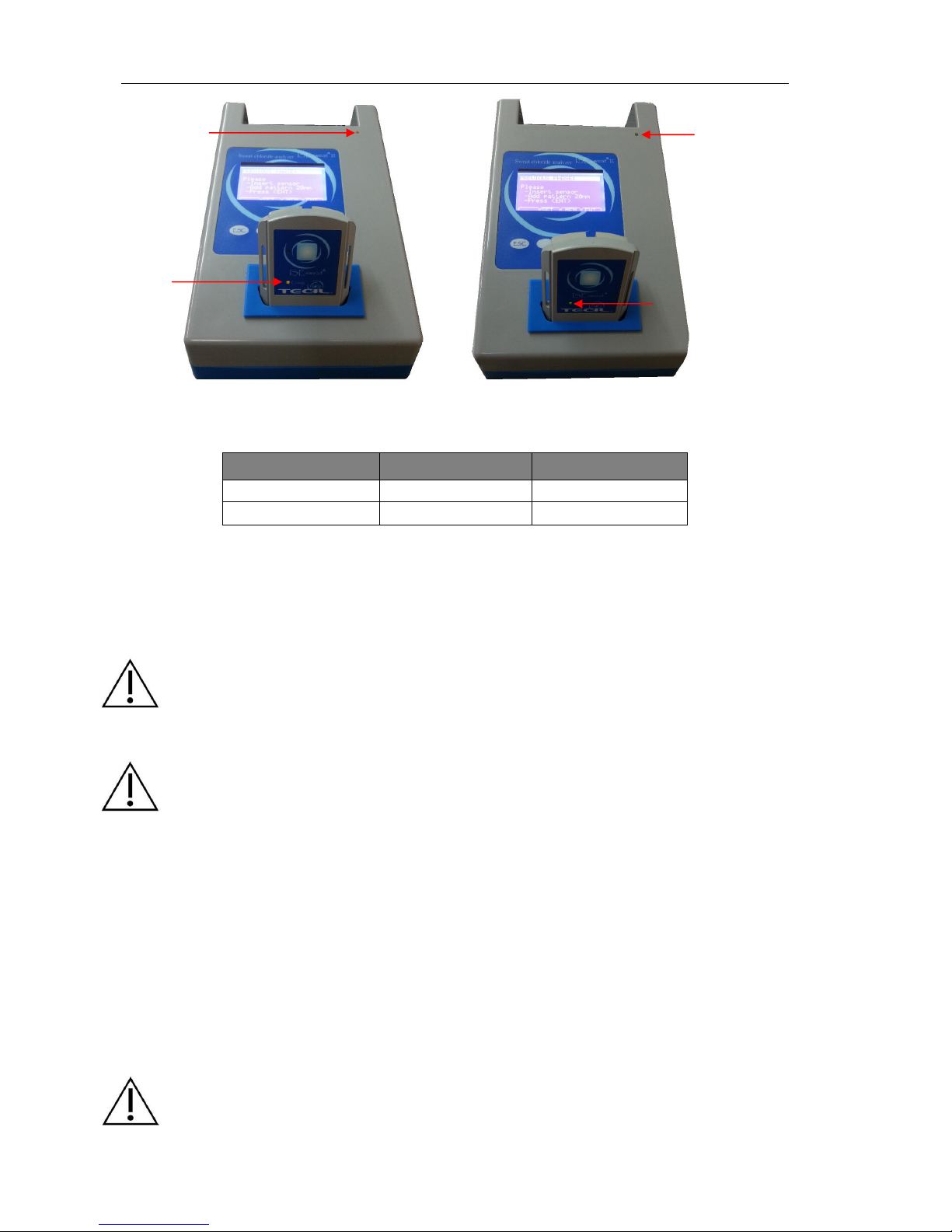
Once the remote is in the charging slot, the base and remote LED indicators (LED) will light
up, and will give information on the charge state, changing from orange/red to green/green
as shown,.
ORANGE
Page 18
ISEsweat
- User’s Manual 18
Charge light signals indicators:
Battery state
Remote LED
Base LED
Discharged Orange* Orange
Charged Green Green
*No more than 7 hours. In any other case, check Problems chapter.
Once the battery is fully charged, base and remote LEDs will glow GREEN, thus indicating
the battery is at full charge.
The remote module can remain connected to the base indefinitely, without any problems for
the equipment. LED indicator will remain GREEN at all times.
WARNING: Make sure when using the remote again, to set the side switch to the ON position.
In fact it won’t connect to the Base Unit or work at all until you do this. If after charging for 7
hours, the remote LED is still showing Orange, there is the possibility that you have
forgotten to disconnect the remote, because the remote’s minimum power consumption
prevents the remote from becoming fully charged (Green LED).
WARNING: If you remove the remote from the charging slot with the green LED showing
(charged battery) and replace the remote back in the slot the LED will glow red for a few
moments even though the battery is fully charged,, because the remote needs some time to
check the battery state.
Battery change
The advantages of the Lithium Ion batteries are, among other things, the lightness of their
components, their high power capacity and their capacity to operate with a high number of
regeneration cycles. However, the battery life will deteriorate over time. The number of
battery charge/discharge cycles will determine its service life; with regular use, its useful life
is estimated at between 2 and 3 years. It is highly recommended that the battery is left in the
charging position when you don’t expect to be using it for a long time. As said before, check
the Problems chapter if you observe any charging anomaly.
Remote indicator LED will emit a RED light if the battery state is not good, thus showing a
problem in the battery.
CAUTION: Battery replacement can only be made by the TECIL Technical Support team or a
TECIL authorized technical expert.
ORANGE
ORANGE
GREEN
GREEN
Page 19

4. Sweat analysis
Page 20
ISEsweat
- User’s Manual 20
4.1 Settings
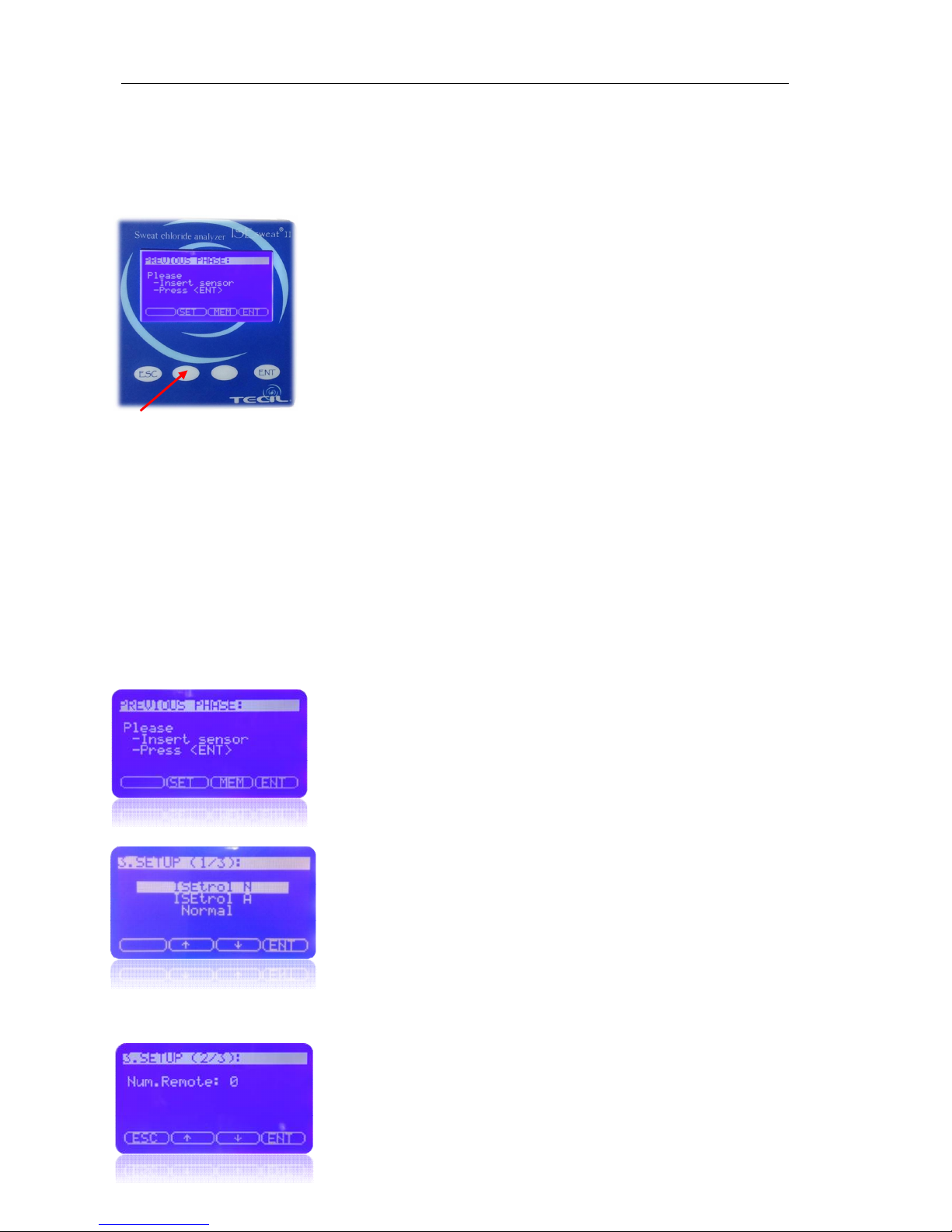
SETUP (SET).
Once the equipment is ON, and after the software has been
loaded (you have to wait 10 seconds for this), the Start screen
will appear. On the lower part of the screen, you will see <SET>
This is the access portal to the Settings Menu (Setup). Using
this menu, you can choose between different Work Modes.
ISEweat® is designed to run the Sweat Test and to establish the chloride concentration in a
sweat sample.
To do so, ISEsweat® has 2 work modes:
Normal Mode, designed to run the analysis or sweat test.
Quality Control Mode ( ISEtrol N or ISEtrol A ), designed to check the equipment. It
is recommended to use TECIL controls or any other approved QC material for this.
Work Mode Selection
Press <SET> at the Start Screen.
A menu will appear that allows you to choose between
different programs or Work Modes:
QC (ISEtrol N or ISEtrol A) or Normal (Sweat Test)
Use the scroll arrows to select a program from the control
panel.
Press <ENT> when you have selected the Work Mode
you want to use.
You will see the Remote Linking menu screen, both in Quality Control and in Sweat Test
modes
The factory setting of the remote number is zero. Skip
through this by pressing <ENT>
Page 21
ISEsweat
- User’s Manual 21
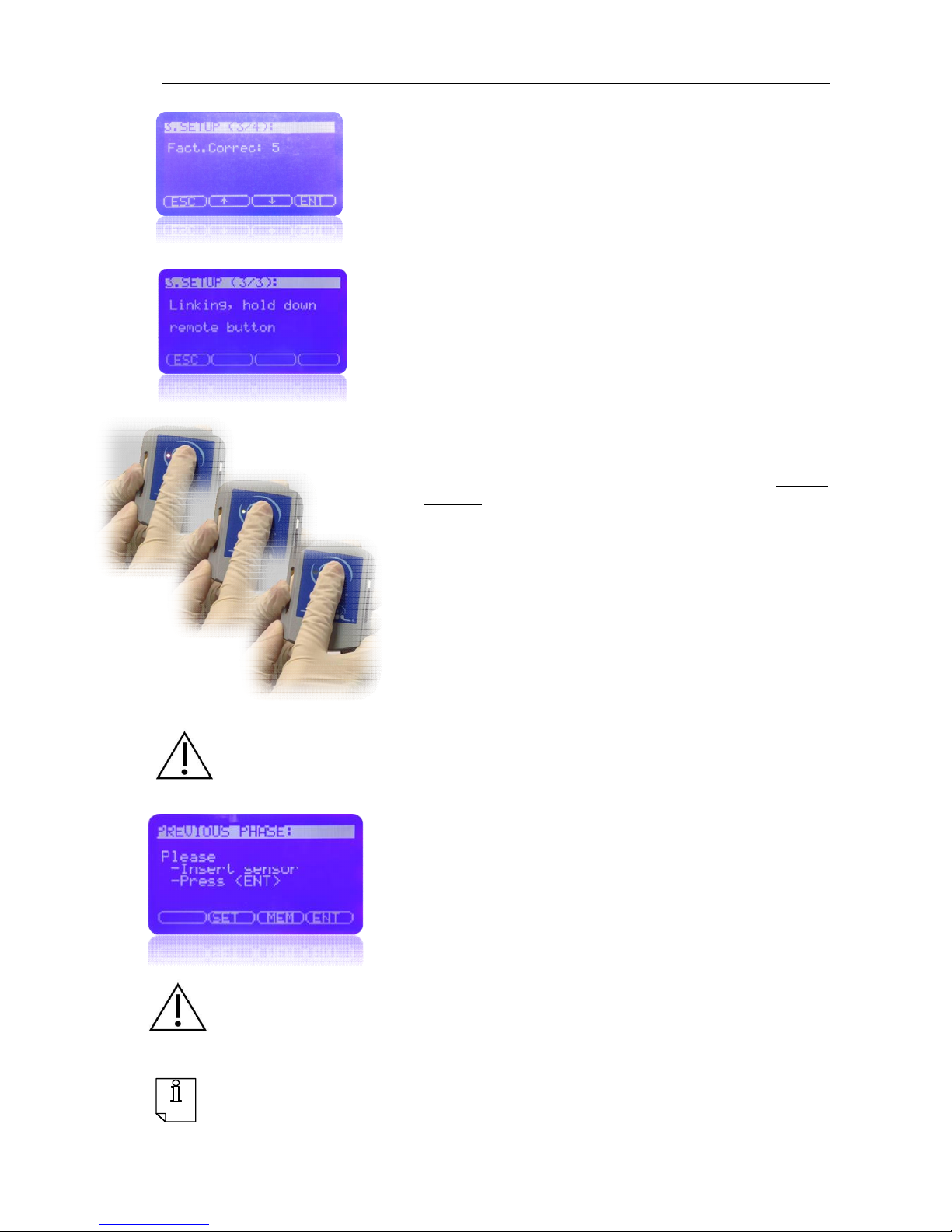
Choose the correction factor that shows in the sensor
card box, if there is not any specified on the box, choose
5. Skip through this by pressing <ENT>
An information screen on the linking between the base and
the remote will appear automatically, and the device will
proceed to the linking. To indicate this process, the base
unit will emit a series of 3 beeps
Press the remote module central button and keep it
pressed during the process. Do not let it go until the
base stops beeping.
During this 10 seconds (approximately) interval, while you
keep .the remote module button pressed, the remote LED
will indicate that the remote is correctly linked by the
following color sequence
WARNING: Keep in mind that it is very important to keep the central button of the remote
pressed all the time until the linking is done, otherwise the process will be interrupted, and you
will have to initiate the process again until linking is successfully completed.
When linking is completed, the menu screen will change to
the start screen menu, thus showing that correct linking
between the base and the remote has occured.
CAUTION: In order to have good communication between the base and the remote, the
distance between the two must not be over 10 meters. If you increase this distance, there is
the possibility that the link between the remote and the base breaks which could lead to some
errors.
NOTE: Interruption of the analysis. You can stop the test at any time by pressing the button
on the remote unit until the LED remains orange (4 seconds) and release. Return to the Home
screen.
Page 22
ISEsweat
- User’s Manual 22
4.2 Sweat induction and analysis
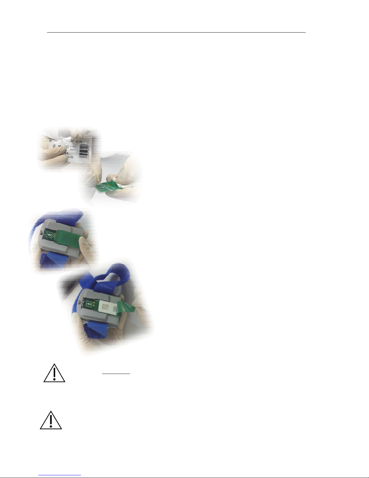
PREVIOUS PHASE
Follow the instructions on the screen:
Insert sensor
1. Select a card and take it out of the package
2. Remove the protective film plastic that protect the
connectors. Dry any excess liquid from the
connections zone with a tissue
3. Before starting the analysis, locate the IONTO side
of the sensor card.
NOTE: The IONTO side of the card is designed for skin
stimulation, in order to obtain a sweat sample prior to
running the sweat test in the Normal Mode.
4. Place the sensor card with the IONTO side facing
outwards in the remote connector slot, as shown in
the image.
5. Remove the protective plastic protector strip on the
IONTO side.
CAUTION: Please, do not touch the hydrogels on the IONTO side; it could affect their
composition. Pilocarpine found in the hydrogels can be toxic if inhaled or ingested. Please,
clean carefully all contact zones after the analysis. In some cases, depending on the patients
sensitivity, the gels can cause an allergic reaction such as red spots on the skin which may
need to be treated with anti-inflammatory treatment. If the patient suffers any distress or pain,
STOP the test immediately and cancel the analysis
CAUTION: In case you introduce the card the wrong way round (opposite side of the one
needed); the remote LED will remain red. Extract the card, turn it round and introduce it again,
correctly. The LED will go out and you can continue the procedure.
Page 23
ISEsweat
- User’s Manual 23
CAUTION: Skin must be healthy, wholesome, with no cuts, eczemas or irritations. Whenever
you clean the skin with alcohol, remember to moisturize it afterwards, to avoid skin dryness
caused by alcohol
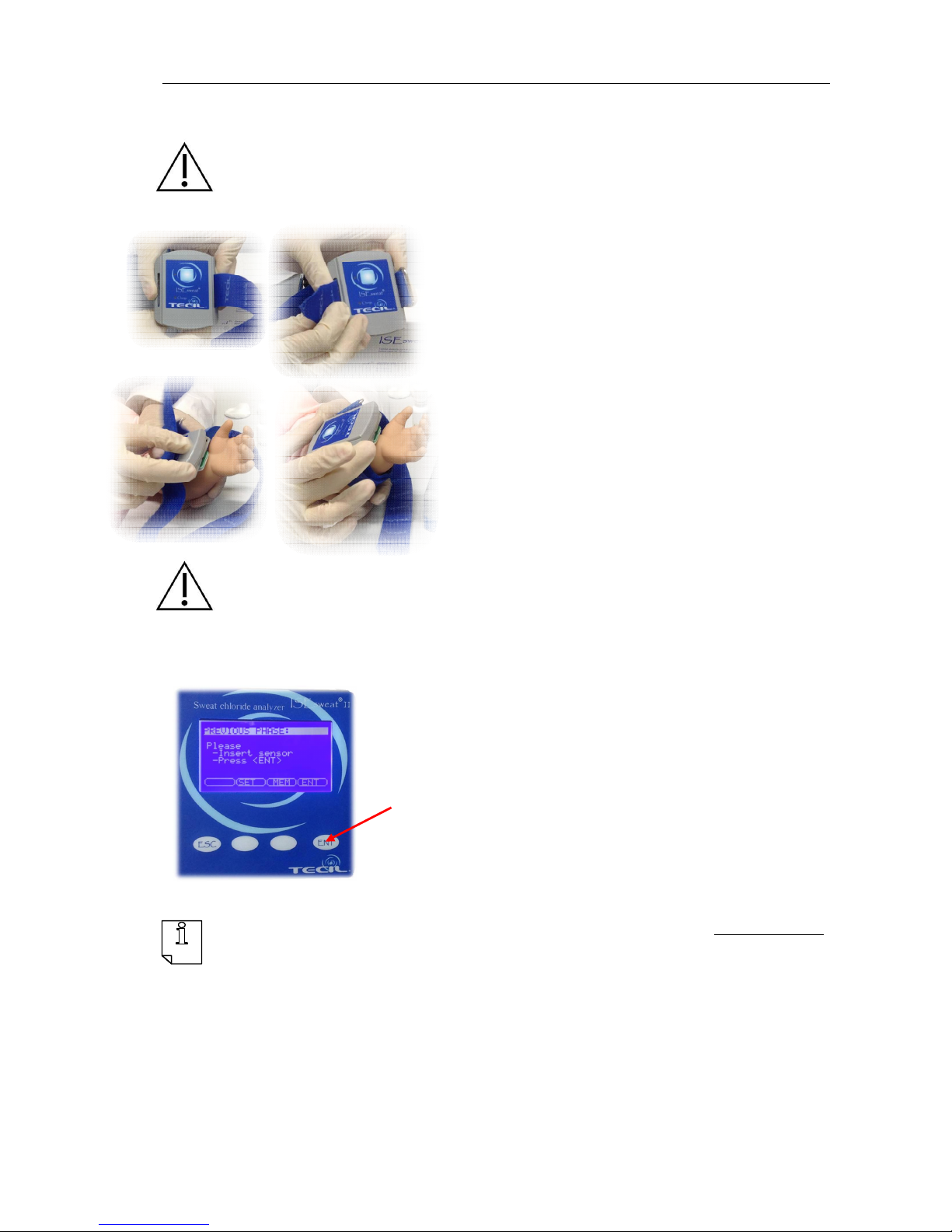
6. Place the card with the hydrogels on the skin
pretreated with alcohol and destilled water, so there
is contact between them and the patient’s inside
forearm.
7. Fix the card and the remote module to the patient’s
forearm using the armband. Adjust the armband as
shown on the image, so the sensor card stays fixed
on the patient’s arm.
a. Enter the rounded end of the armband into the
slot with the cloth part on the inside.
b. Without twisting, insert the end of the armband
into the other slot.
c. Adjust the size of the armband to fit the forearm
so that the hook side attaches to the cloth side.
CAUTION: It is very important that the remote unit is fixed securely in place by the armband, in
order to maintain good contact with the skin and to prevent sample evaporation and
subsequent concentration of sample
Press <ENT>
8. Once the card and the remote unit are fixed on the
patient’s forearm, press <ENT> on the receiver base
unit.
NOTE: To avoid burns, the ISEsweat® is equipped with a current generator limited to 0,4 mA.
Current is generated at the remote unit for 10 minutes, so the distance between remote and
base units will not affect the analysis during this time.
Page 24
ISEsweat
- User’s Manual 24
Sweat Test
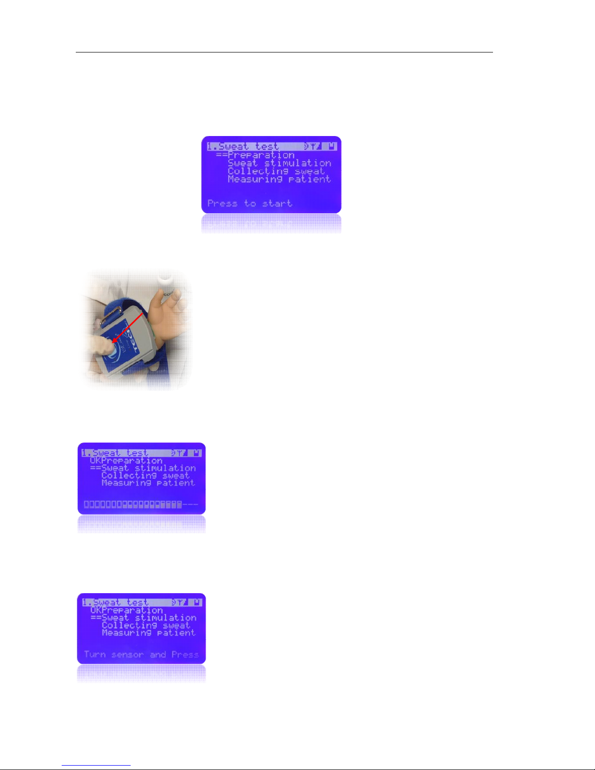
On pressing <ENT>, a new screen appears which allows the analysis to be monitored. The
analysis consists of 4 phases:
Phase 1:
Preparation
The ISEsweat® base unit will emit a repetitive sequence
of 3 fast beeps, waiting for the user’s confirmation.
1. once the device is correctly placed on the patients’s
forearm, press the remote button..
2. The Base unit beeps will stop and an OK will appear
on the screen next to Preparation.
3. The process will continue to the next phase, Sweat
stimulation, in which, sweat is stimulated from the
patient’s skin by means of the IONTO
Phase 2:
Sweat stimulation
A flashing green light signal on the remote module
shows that the sweat stimulation has started.
The screen shows that the sweat stimulation has start
==
The sensor card stimulates sweat generation for 10 minutes through iontophoresis at the
place it is lying on. During this 10 minute period, the remote unit will flash with a green light,
to show the user which phase it is in.
4. Once 10 minutes has elapsed, the remote unit will
stop delivering current and the acoustic signal will
change to 3 consecutive beeps. The screen will
display the words “Turn sensor and Press”.
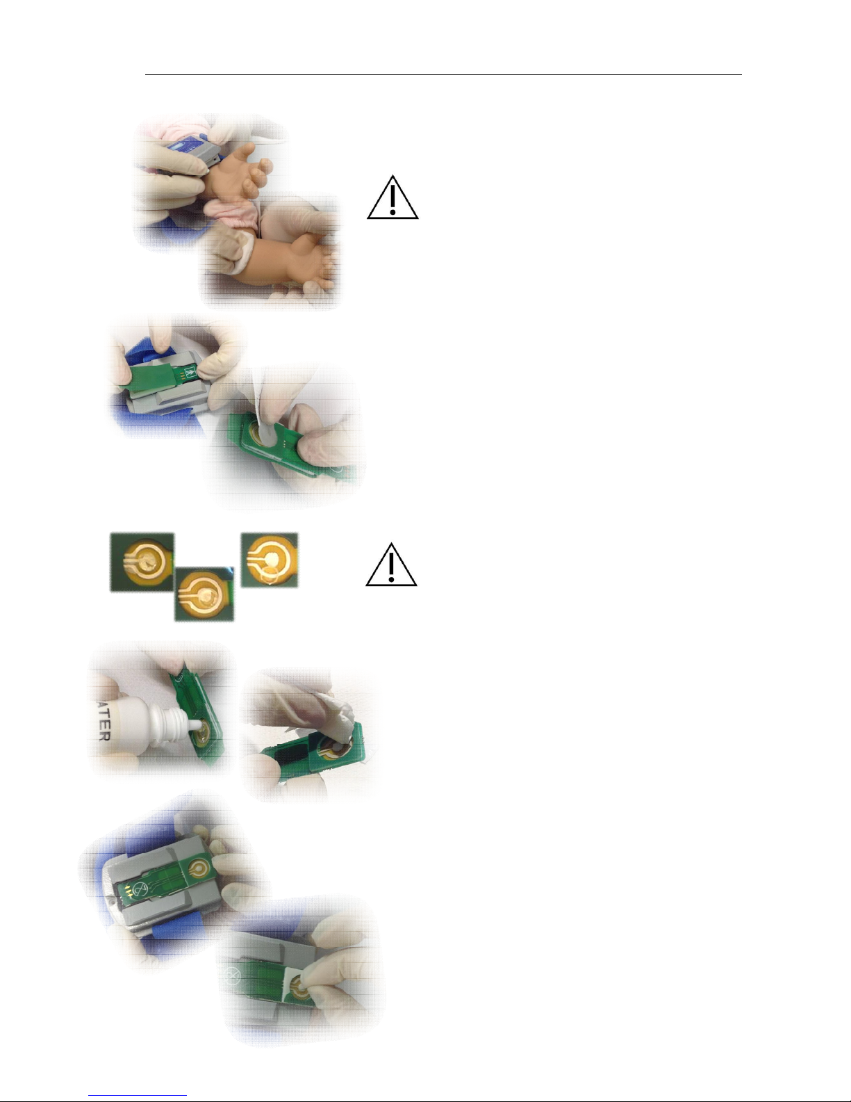
5. Loosen the armband and remove the remote unit
from the patient’s forearm.
Page 25
ISEsweat
- User’s Manual 25
6. Clean the stimulated zone with deionized water and
then dry it.
CAUTION: DO NOT clean the stimulated zone with
physiological saline or any other saline solution, since
it can affect the test results.
7. Replace the protective plastic covering over the
IONTO gels.
8. Then carefully remove the gel that covers the
electrode on the measure side. Be careful you don’t
damage it. You can remove it with bare hands or with
tweezers.
Do not use sensor cards in case that reference
electrode is broken or in disrepair. (see image)
9. Clean the card surface to avoid leaving bits of gel on
the electrode. Clean with plenty of distilled water, and
dry with a gauze or blotting paper. The cleaning
process is finished when the water drops are gone.
10. Fit the sensor card into the remote unit connector
slot, with the MEASURE side upwards as seen at the
image below.
Page 26
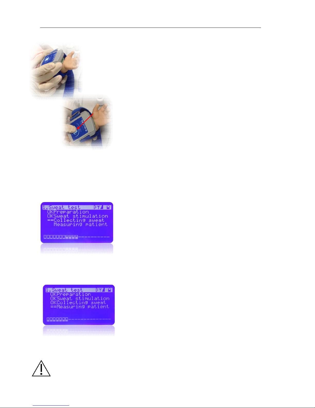
ISEsweat
- User’s Manual 26
11. Place the remote unit onto the patients skin with the
electrodes aligned over the stimulated zone.
IMPORTANT: Keep the remote unit in the same position and
direction as it was before to ensure that the measure area is
placed directly over the previously stimulated area.
12. Fix the remote unit to the forearm with the armband
again.
13. Press the remote unit button.. The “Collecting
sweat” phase will start automatically and the bips
stop.
The electrode position is very important. The measurement electrode must be in contact with
the skin, directly over the previous stimulated zone (reddened zone). If it is anywhere else
the sample of sweat generated may not be enough to give a result or the measurement
electrode may not have a good contact with the sample, so you won’t get a good result.
Phase 3:
Collecting sweat
14. The screen shows:
The remote makes a repeated visual signal of two green
flashes.
This process lasts for 10 minutes. During this phase, the
remote unit needs to receive a sufficiently amount of
sample to be able to analyze it (see Technical
specifications chapter).
Phase 4:
Measuring patient
15. Once 10 minutes of the Collecting sweat phase is
over, the equipment will automatically start the
Measuring patient phase, where it will measure the
chloride concentration of sweat, without further user
involvement.
16. The screen shows:
== “Measuring patient”
17. The Measuring patient process takes 5 minutes; after
this, the equipment sends the result from the remote
unit to the base unit.
CAUTION: During measuring phase, it is important that the distance between the base and
the remote is no greater than 10 meters. If it’s any greater it could lead to a break in the link
and the test would have to be repeated.
Page 27

ISEsweat
- User’s Manual 27
Results
Once the data has been transmitted, the base screen will
show the value Chloride concentration in mmol/l.
The screen message has a reminder that, after ending the analysis, you have to:
1. Remove and discard the sensor card (see Waste Management).
2. Press <ENT> to go back to the Start Screen or Previous Phase screen. From there,
you can run a new analysis.
After obtaining the concentration value in mmol/l, the equipment will automatically send the
results to the printer, if conected.
4.3 Interpreting of sweat test results
Reference Values
Negative value < 40 mmol/l*
Intermediate value 40 ≤ X ≤ 60 mmol/l*
Positive value > 60 mmol/l
* To newborn < 30 mmol/l Negative value
30 ≤ X ≤ 60 mmol/l Intermediate value
4.4 Calibration and control
The ISEsweat is factory-calibrated and does not requiere any calibration by the user.
Together with the device the control solutions with two levels are delivered, 20mmol/l and 80
mmol/l.
All quality control requirements and testing should be performed in conformance with
local, state and/or federal regulations or requirements.
At least, once a month do the measures of both controls levels (See next section), if the
results are out of range, please contact immediately to our technical service and put the
device out of service.
Page 28
ISEsweat
- User’s Manual 28
4.5 Quality Control Mode (QC)-ISEtrol N and ISEtrol A
As has already been said in this manual, the usual working mode for the ISEsweat® is the
NORMAL mode, to run sweat tests, but, to carry out Quality Control you need to change the
Work Mode. To do this, please follow the instructions in the Settings chapter, and select
Quality Control Mode (QC) ISEtrol N or ISEtrol A as the work mode.
To verify the correct operation of ISEsweat® it is recommended that you use ISETROL
controls. The ISETROL controls are suitable for ISE (electrode ion selective) analysis of
chloride, and are within the optimum working range of the device (see Technical
Specifications section).
CAUTION: TECIL not responsible for any problems arising from the use of a control in poor
condition or unsuitable for the technique or device. Therefore, before using a control, you
should consult with TECIL as to its compatibility with the ISEsweat. Each hospital or laboratory
should decide for itself the quality control steps to be taken but TECIL recommended to
perform a quality control each day before the first test of your work list.
REMEMBER: To avoid confusion, please change back to Normal Mode once Quality Control has
finished.
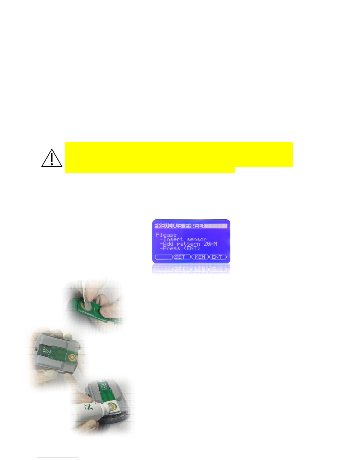
Select QC Work Mode , ISEtrol N or ISEtrol A (see Work Mode chapter 4.1)
The Start screen QC will appear
1. Take a sensor card out of the package
2.
Then carefully remove the gel that covers the
electrode on the measure side. You can remove
it with bare hands or with tweezers Clean the
card surface with plenty of deionized water and
dry with a gauze or blotting paper.
3. Fit the sensor card into the remote unit connector
slot, with the MEASURE side upwards as seen at
the image.
4. Put the remote unit in a horizontal position, on an
even and horizontal surface, with the electrode
facing upwards. Wait 1 min.
Page 29
ISEsweat
- User’s Manual 29
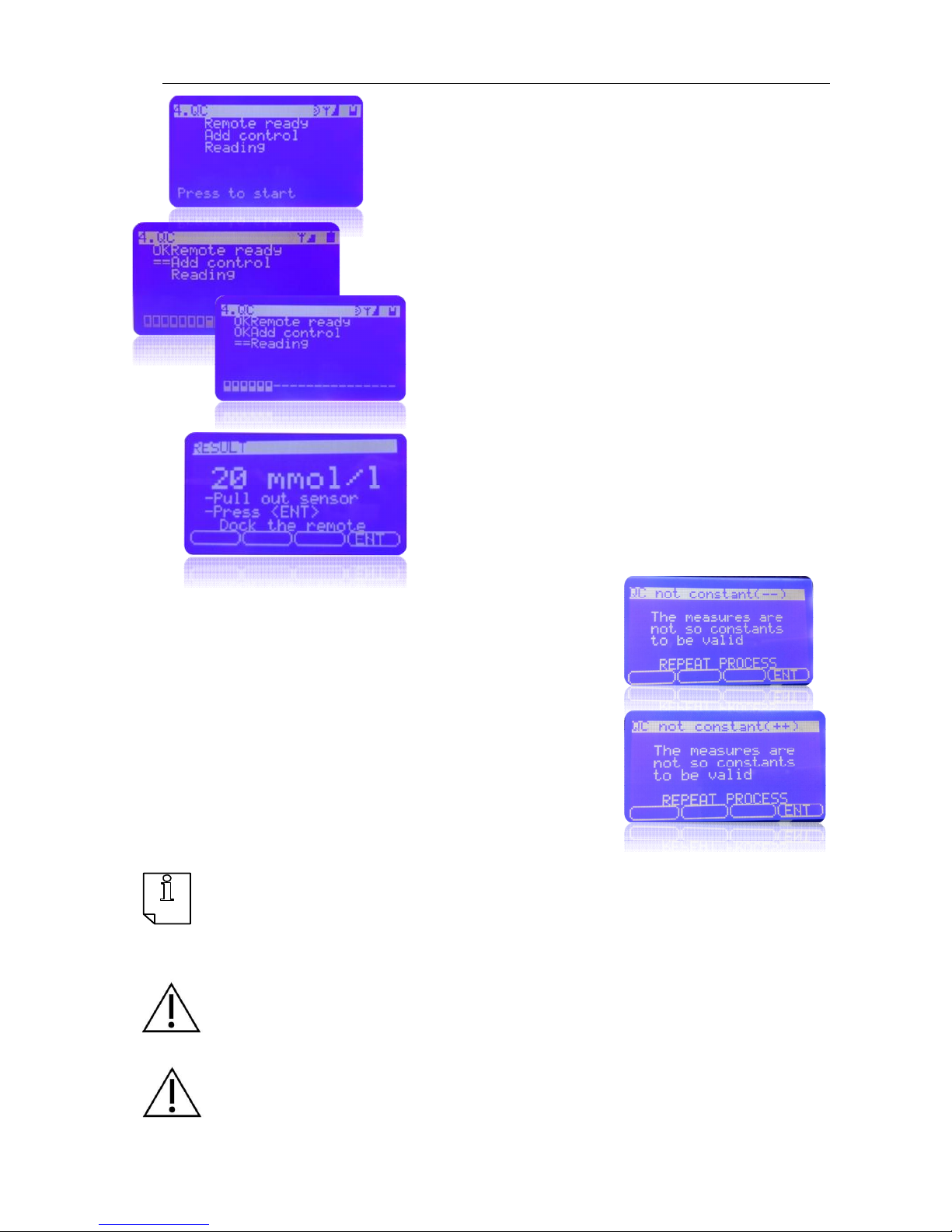
5. Add a control solution drop directly onto the
measurement electrode
6. Press <Ent> on the base to start the QC
process. The base will emit three beeps
repetitive to confirm that the user is ready to
start. And appear the next screen
7. Press the remote unit button.
8. Next to each phase will be appearing OK to
indicate that the phase has been realized
9. 4 minutes later the device will calculate the
chloride value of the control
10. After obtaining the concentration value in
mmol/l, the device will automatically send the
result to the screen and the printer, if fitted.
** If Appears the screen QC not constant ( - - )
Please clean the drop and place it in another position.
Press ENT on to the base.
** If appears the screen QC not constant ( ++ )
Please ENT on to the base until the QC re-start .
NOTE: The Manufacturer should provide an acceptance range as well as the certificate
analysis for the standardized control. Take into account expiry dates.
Each laboratory will need to establish its own quality control procedures, but it is highly
recommended to run a control before the beginning of a series of analysis and each time a
new batch of sensor cards is used.
WARNING: Values that are out of range might indicate some anomalies. If after several tests,
values continue to be out of the range suggested by the manufacturer, you must contact the
manufacturer and stop using the device. Get in touch with TECIL for instructions on possibly
changing the cards, or the control, or the device.
CAUTION: TECIL cannot take responsibility for any problem arising from the use of controls
that are in bad condition, or controls that are not suitable for the device or technique. Thus,
before purchasing a control, it is highly recommended that you check its compatibility with the
device. Check with TECIL if you have any doubts.
Page 30

5. Data port use
Page 31
ISEsweat
- User’s Manual 31
5.1 General summary
You can obtain patient data through the data ports at the back of the ISEsweat® if you
connect it to a PC or to a printer in series such as Epson TM-U220DS M188D.
When you connect the ISEsweat® to the printer or the PC, you must check that it works
correctly before using it in a clinic. Both the ISEsweat® printer or the PC must be connected
to an AC power source with an earth connection.
WARNING: Epson Printer TM-U220DS is certificated according to EN 60601-1-1. The
serial port is designed for this printer. Do not use any other printer. If you have any
doubt, please check with TECIL Technical Support Service.
CAUTION: When connecting any peripheral equipment, either the printer or the PC, to
the ISEsweat® base, all equipment must be disconnected (OFF). Do not connect or
disconnect any cables or wires while the device is working.
Any printer or PC connected to the ISEsweat® data port must be certified under the EN
60950 regulation. All equipment combinations must follow all the requirements of the EN
60601-1-1 regulations. Any person that connects a printer or a PC to the data port is
configuring a medical device, and as such is responsible of guaranteeing that the system
follows the EN 60601-1-1 and 60601-1-2 regulations on electromagnetical compatibility
(EMC).
5.2 Data port connection
ISEsweat® data port can be connected to a printer via a Printer Series Dock Cable (code
T900) or to a PC via a USB cord (code T902).
5.3 Print Data
The printer must be connected before the analysis starts. Data can be lost if it is not
recorded, so it is highly recommended that you check first that the printer is connected and
that it has enough paper.
To print:
1. Connect the printer in
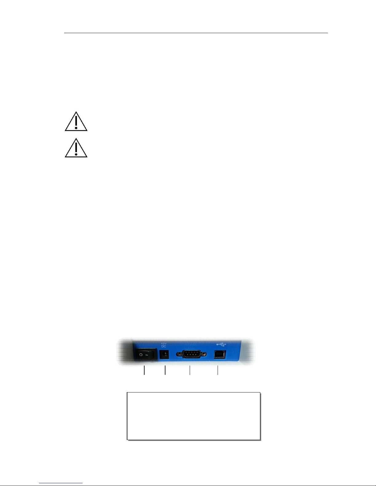
1 Power supply On/Off switch (—/O)
2 AC Power supply connector
3 Data port connector
4 USB port connector
1
2
3
4
Page 32
ISEsweat
- User’s Manual 32
series to the ISEsweat® data port connector (4).
2. Turn on the printer.
At the end of each analysis, data is sent in real time and continuously to the data port at the
back of ISEsweat®.
Each analysis results (both Sweat Test and QC) is seen on screen and is simultaneously
transmitted to the communication outputs at the back of the device
As long as the printer is connected to the device, and working, results of each analysis will
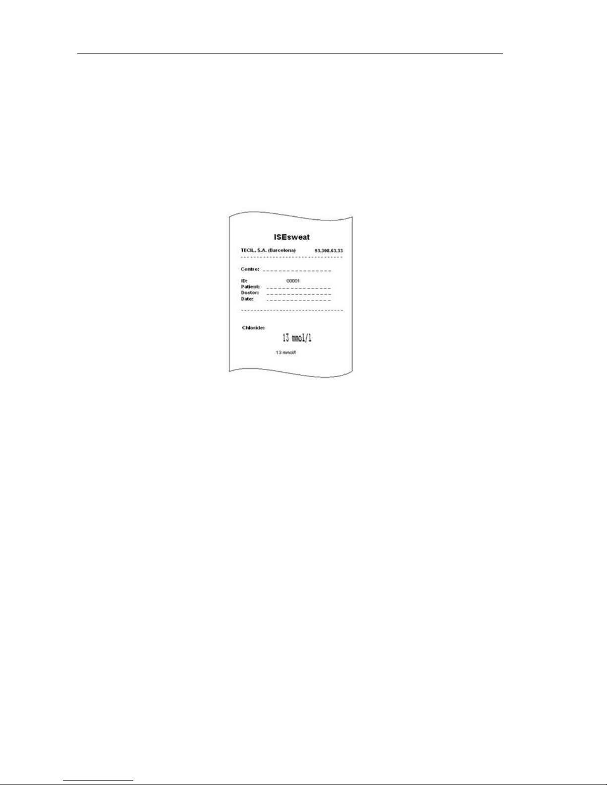
be sent to the printer at the same time that they appear on screen. The printing format is as
shown in the following figure
The printing shows the chloride results expressed in mmol/l, and an identifier (ID)
corresponding to the number of samples recorded on the internal meter.
Once printing is done, the user can write the laboratory identification number, as well as the
patient’s name, age, the analyst’s name, the date and any other observation that may be
needed.
If the printer is not connected when the results appear, this value will be stored in the
equipment memory.
Page 33
ISEsweat
- User’s Manual 33
5.4 Memory
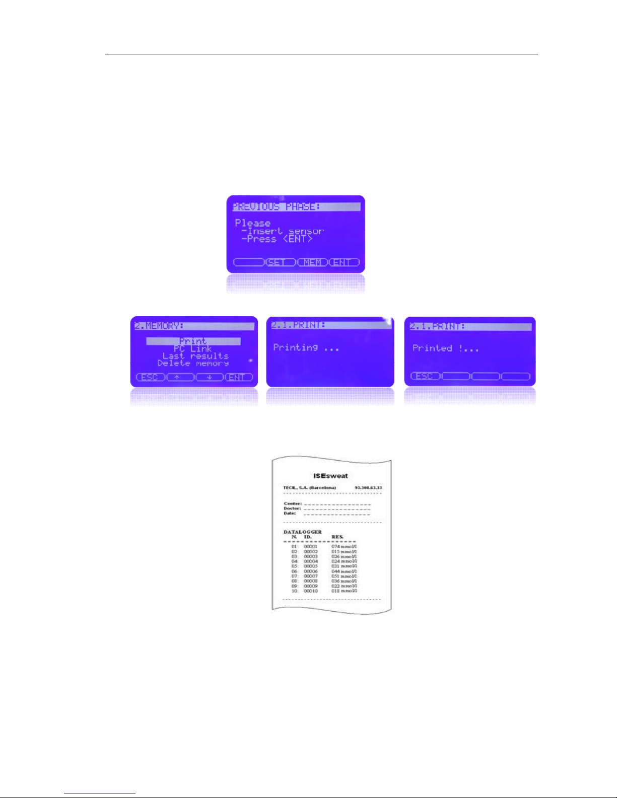
The ISEsweat® memory is capable of storing up to 50 results that can be printed out later or
sent via the USB port to a computer connected to the base.
To open the MEMORY menu, press <MEM> at the buttons below the Start Screen.
Choose Print and press <ENT> in order to print the stored results.
.
The printing format for the memory results is shown in figure. ISEsweat® will print the last
50 results, both QC results and Normal results.
Page 34
ISEsweat
- User’s Manual 34
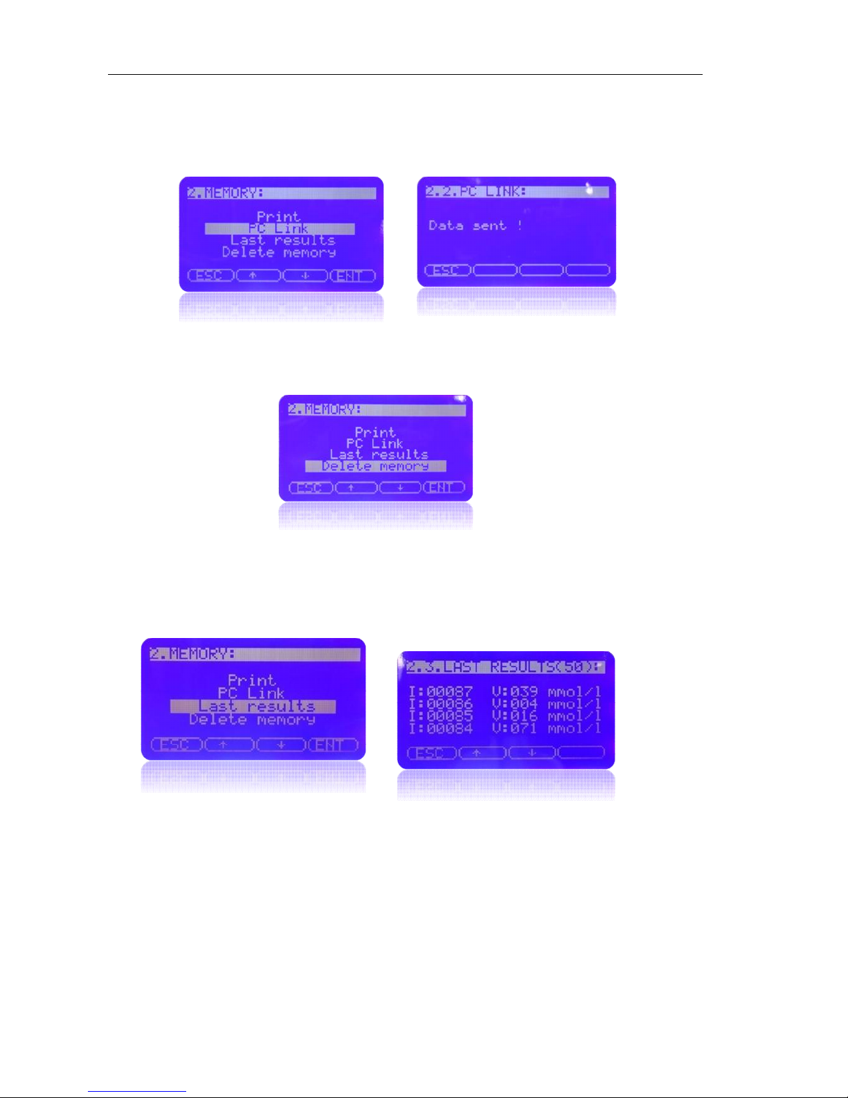
Choose PC Link using scroll arrows (↓↑) and press <ENT> in order to send the
stored results via the USB port to a computer connected to the base.
.
Choose Delete memory using scroll arrows (↓↑) and press <ENT> to delete all
stored results. Once you have erased the memory, the identifier sequence number
will be reset.
Press <ESC> to go back to the start screen
.
Choose Last results using scroll arrows (↓↑) and press <ENT>, the screnn shows the
last 50 results
Press <ESC> to go back to the start screen
Page 35

6. Maintenance
Page 36

ISEsweat
- User’s Manual 36
ISEsweat parts missing
Check the components
Remember:
- If you think any accessory is missing, please check carefully all the package contents.
If you do not find the missing piece, please inform TECIL logistic department at once.
TECIL can only take responsibility for missing items if notified within 15 days of
receipt.
- If you receive any damaged items, please keep the packaging material for later
inspection and inform the TECIL logistics department within 24 hours of receipt.
If you are returning goods to TECIL get in touch with TECIL Technical Support Service to get
shipping instructions. Unless TECIL Technical Support Service says otherwise, you don’t
need to return sensor cards or any other accessories with the ISEsweat®.
Send ISEsweat® with the original package. If you don’t have the original package, please use
an appropriate box and adequate wrapping material to protect the ISEsweat® during
shipment. If you have any doubt, please check with TECIL Technical Support Service before
sending the device.
6.1 Technical service
The ISEsweat® does not need a routine technical service or calibration, but the battery needs
to be changed every 24-36 months. Check the battery change process in the ISEsweat® user
manual (Battery change chapter).
6.2 Periodic security check
It is recommended that you do the following every 24 months:
- Check the equipment for any mechanical or functional damage.
- Check the security and information labels to make sure they are still legible.
6.3 Cleaning
CAUTION: Do not spray, pour or spill any liquids on or near the ISEsweat® or its connectors
and switches.
You can clean the ISEsweat® whenever you think it is appropriate, or in accordance with
procedures laid down at your Hospital or Laboratory. Please bear in mind:
- ISEsweat® surfaces can be cleaned with a cloth slightly moistened with a commercial
non-abrasive cleaning product or alcohol, but don’t rub too hard.
- Make sure the data port connectors on the base unit are dust free with a dry cloth.
Connectors on the remote unit will accumulate grease because they are in contact
with the skin. Clean them with alcohol.
Page 37
ISEsweat
- User’s Manual 37
6.4 Waste management
International concern on environmental pollution, due to improper disposal of products and
materials after use, has increased the legislation control on the methods and procedures of
waste management for electric and electronical devices. Although in some countries the
regulations have increased to the point that they are part of the official laws, in other regions
this process is still ongoing. The result is a tighter control over product waste disposal and
over recycling components once they are out of use. Check WEE Directive (waste of
electrical and electronical equipment) 2002/96/EC for more information.
Regulations on instrument and accessory disposal may change according to where you are,
so TECIL suggests the following guidelines to help determine the available options when
taking the decision to replace or discard items:
• Contact TECIL or any authorized representative to gather information on the national and
local regulations about product disposal and recycling in your area. In some cases, the
provider may be legally obliged to take the product back and arrange for its correct disposal.
Alternatively, the provider should be able to give specific instructions regarding correct
product disposal.
• Contact your local government department responsable for waste collection and disposal.
They can help you determine the current procedures and restrictions which apply, in order to
ensure proper disposal. They can also inform you of suitable places to dispose of items .
• Contact TECIL Support Service:
Technical service
TECIL staff will give you local contact details for product disposal, or instructions to ship the
product back to TECIL.
CAUTION: The ISEsweat® uses single-use sensor cards. Once used, they must
be discarded. Do not throw them in the waste bin. Like any other material
subject to possible biological contamination they should be discarded in a
container designated for biological waste.
Page 38

ANNEX A: Troubleshooting Table
Page 39
ISEsweat
- User’s Manual 39
Error/Action codes
There is a possibility that the remote module cannot link correctly with the receiver base due
to background interferences. The signal symbol blinks when there is a linking error.Make
sure the base and the remote are never more than 10 meters apart.
If the device suffers electronic failure or the remote light signals do not go on after charging
the battery, please contact the technical support service of TECIL or your local distributor.
If there are any of the problems listed in Table 4, follow the instructions given.
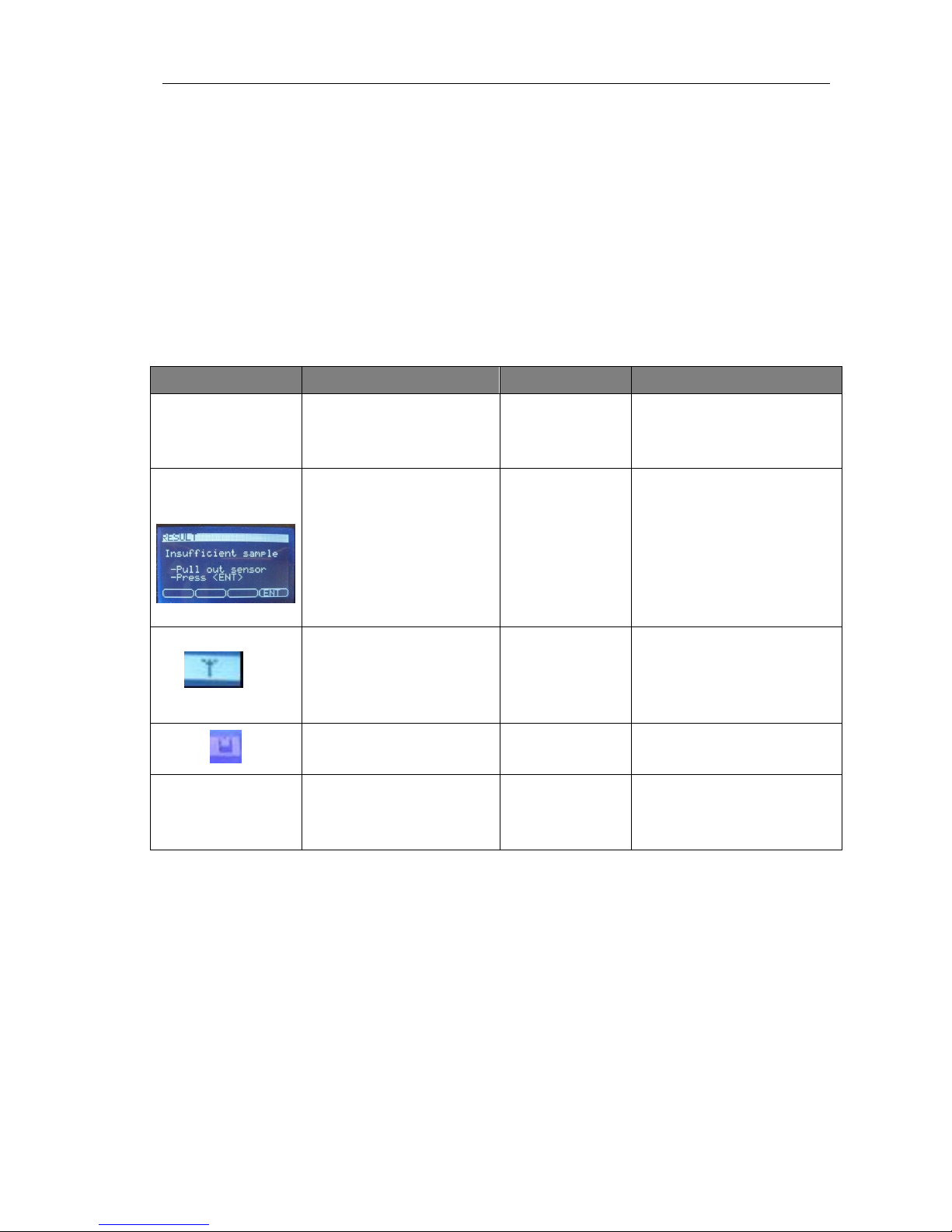
Alarm Problem Cause Solution
Remote link
lost:please bring
the remote closer
to the base
No communication between
remot and base
Interference Repeat the linking
“Insufficient
sample”
There is no sample, the
pattient does not sweat
Patient with
sweating
problems.
Sweating is related to skin
state and other factors that
cannot be completely
controlled.
No signal
Interferences or
distance between
the base and the
remote is greater
than 10 m.
Do not run the analysis in
environments with
electromagnetic emissions or
put the remote closer to the
base.
“ ”
Low battery Lack of charge Charge battery
< 5 mmol/l or >150
mmol/l
Chloride value is over
150mM or under 5mM (out
of scale;)
Sample problems
due to
concentration or
evaporation.
Repeat the test
Page 40

ANNEX B Product Specifications
Page 41
ISEsweat
- User’s Manual 41
Technical specifications
CAUTION: DEVICE ADJUSTMENTS ARE NOT ALLOWED. This device does not require any
kind of internal calibration.
Output
Minimum sample volume 10 microliters
Precision
Limit of Detection
+3 mmol/l
3 mmol/l
Range 5 to 150 mmol/l
Repeatability (CV)
Accuracy (SD)
CV < 7% (10 to 50 mM)
CV < 4% (50 to 130 mM)
SD < 2 for 10 to 50 mM concentrations,
SD < 4 for 51 a 130 mM concentrations
Reference values < 40 mmol/l Negative level.
>40 ≤ X ≤ 60 mmol/l Doubt level
> 60 mmol/l Positive level.
NOTE: The sweat test requires human manipulation and the collection of very small samples of
sweat. This can give rise to measurement errors, however, if results are lower than 10mM or
greater than 150mM they will not be of any diagnostic significance.
Electrical specifications
Reading LCD screen with graphic capability
Power 100V – 240VAC, 50/60Hz, 0.8 A
Base 12 V, 2.5 A, 30 W max
Remote module 24 VDC; 0.4mA; 10mW max.
RF Communication 833 Mhz Europe / 902.15 ~902.25 Mhz USA
Firmware CIIPLUS
Remote battery life 10 samples without recharging battery
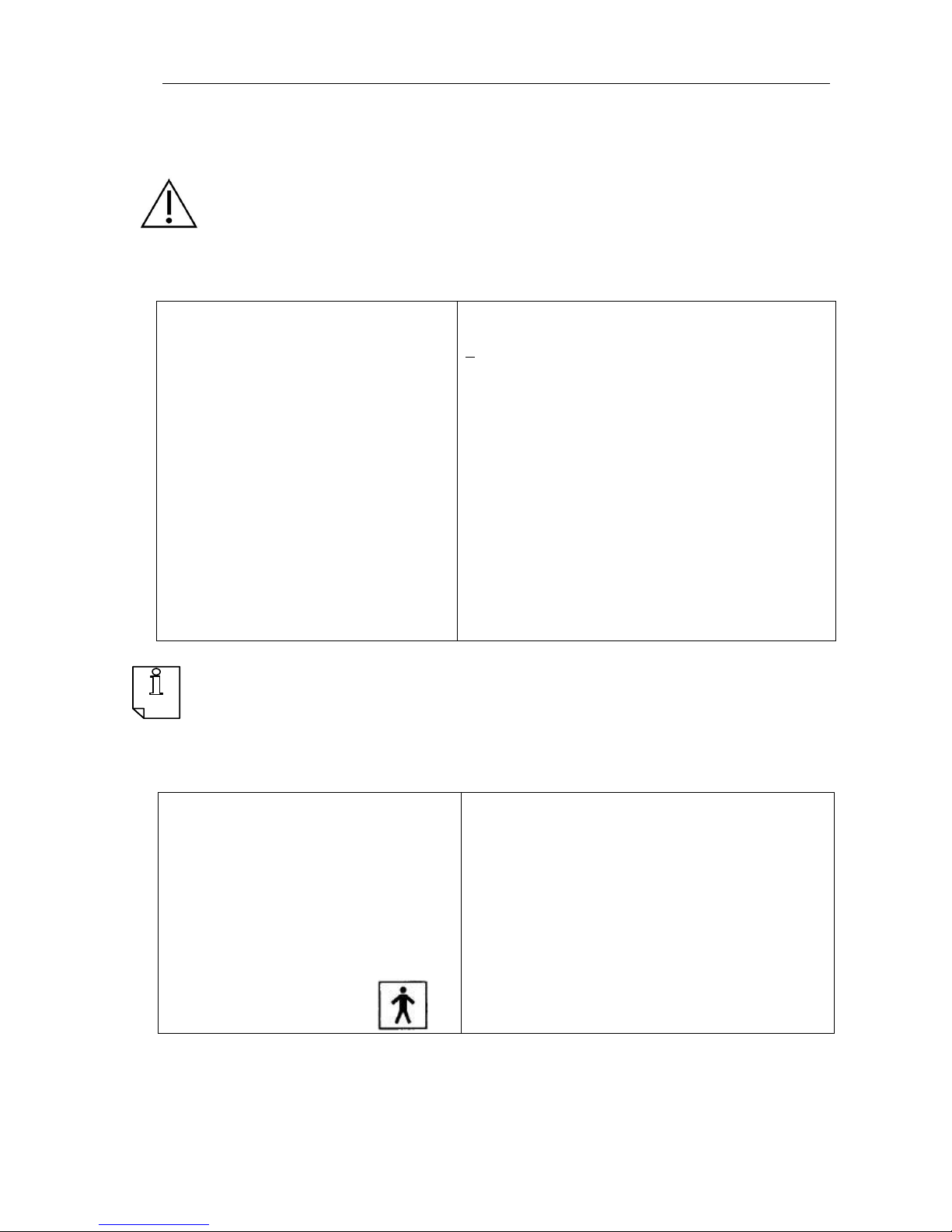
Equipment classification
Protection class: Class I
Applied part type: BF
Work: Continuous
Page 42

ISEsweat
- User’s Manual 42
Background conditions
Storage conditions
Device: keep between 18ºC and 35ºC
Cards: keep between 2ºC and 8ºC
Environmental use conditions 18ºC – 35ºC, Humidity 50 – 80%
Physical features
Dimensions
Base
Width: 150 mm, Long: 195 mm. High: 60 mm
Remote module
Width: 556 mm, Long: 75 mm, High: 22 mm
Receiver base weight
553 gr.
Remote module weight
65 r.
Page 43

ANNEX C Possible interference
Page 44

ISEsweat
- User’s Manual 44
Recommendations to realize the sweat test to a patient:
1. To carry out the sweat test without any problem the patient should not be
having administered intravenous fluids in a shorter period of 24h
2. The patient should not have been treated with any medicines that contain
corticosteroids in a period less of 24h.
3. It must take into account the patient's fluid imbalance because dehydration
problems could give a high result.
The analgesic ointment AMETOP could give positive results in the test, so is
recommended not perform the sweat test in sites where Ametop has been applied
within the previous 24 hours.
Page 45

ANNEX D Recommendations for the
results interpretation
Page 46
ISEsweat
- User’s Manual 46
Causes for repeating the sweat chloride determination (Sweat Test)
All positive results of chloride in sweat must be repeated and confirmed with the mutation
determination. CF diagnosis should not be based in only one positive test.
All doubtful results about the chloride results obtained from the sweat test (with a chloride
concentration between 40 and 60 mmol/L) should be repeated. If results are still in the
intermediate level, some additional tests will be useful.
Collection and determination of chloride in sweat must be repeated in CF confirmed
patients who do not follow the expected clinical pattern. In order to monitor the patient’s
course, clinical, laboratory and thorax X-ray results must be coherent with CF diagnosis.
It is particularly important to evaluate patients again whose initial diagnosis was made
based on the delayed growth or on a positive familiar history; or whose clinical symptoms
prior to the initial sweat test disappear, or there features are in keeping with asthma, with
no suppurative lung illness, or where there is a normal growth pattern, without evidence
of Hippocratic fingers, Pseudomonas colonization or any changes in thorax x-rays.
The sweat collection can be repeated at any time after the first test, but it is advisable to
do it when the patient is clinically stable and hydrated, with no accute intercurrent illness
and is not taking mineralocorticoids.
Illnesses or disorders associated with a high electrolytes sweat concentration, not
related to Cystic Fibrosis:
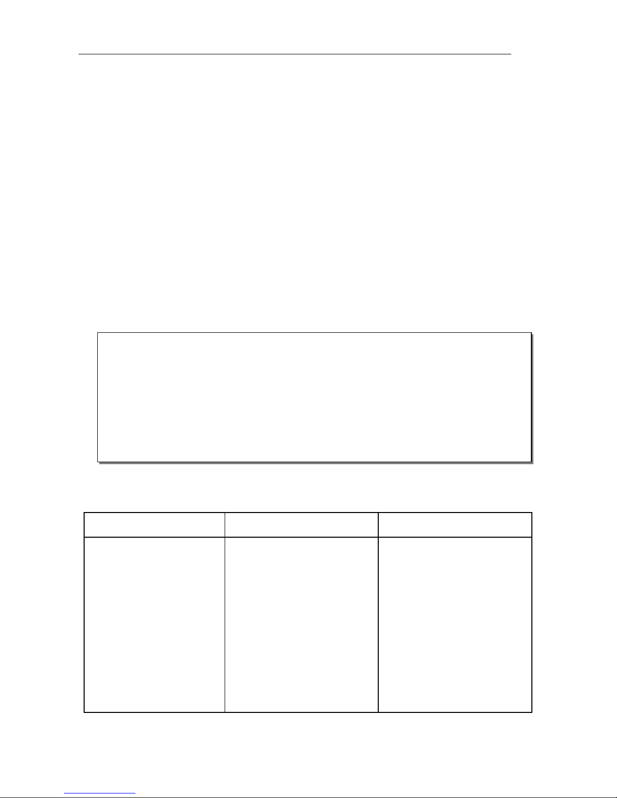
Sweat test indicators: (*)
Pulmonary and upper
respiratory tract
Gastrointestinal Metabolic and others
Chronic cough
Recurring or chronic
pneumonia
Wheezing
Hyperinflation
Tachypnea
Retraction
Atelectasis (particulary at the
right upper lobe)
Bronchiectasis
Hemoptiysis
Mucoid infection by
pseudomonas
Nasal polyps
Pansinusitis
Hippocratic fingers
Meconium ileus
Meconium plug syndrome
Prolonged neonatal jaundice
Steatorrhea
Rectal prolapse
Mucoid impacted appendix
Late intestinal obstructoin
Recurring intussusception
Cirrhosis
Portal hypertension
Recurring pancreatitis
Positive family history
Growing delay
Salted skin taste
Salt crystals on the skin
Salt-depletion syndrome
Metabolic alkalosis
Hypoprothrombinemia
A Vitamin deficiency
(Fontanelle bulging is a key sign)
Azoospermia
Missing vas deferens
Scrotal calcification
Hypoproteinemia
Edema
(*) Taken from CLSI C34-A3 protocol
Anorexia nerviosa Klinefelter’s syndrome
Atopic dermatitis E1 Prostaglandin long term infussion
Autonomic dysfunction Mauriac’s síndrome (malnutrition)
Ectodermal dysplasia Mucopolysaccharidosis type I
Environmental deprivation Nephrogenic diabetes insipidus
Familiar cholestasis (Byler’s disease) Nephrosis
Fucosidosis Protein-calorie malnutrition
Problema de adaptación psicosocial Pseudohypoaldosteronism
Hypogammaglobulinemia Untreatable suprarrenal failure
Glucose-6-phosphate dehydrogenase deficiency Untreatable hypothyroidism
Glycogen type 1 storage disordr
Page 47

ANNEX E Symbol Definitions
Page 48
ISEsweat
- User’s Manual 48
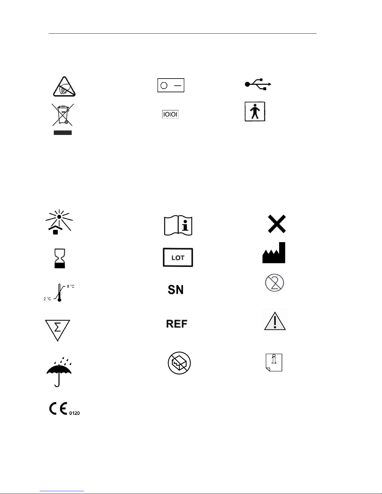
General symbols
Packaging symbols
Do not reuse
Selective refuse collection.
Do not throw to regular
trash.
Electrostatic
discharge
Batch Code
Serial number
Applied part:
Type BF
Temperature limitation
Contents for 10 analysis Catalogue number
Manufacturer
This product complies with European regulations, certified by
a Notified body.
Do not use
if packaging is broken
Avoid water
contact
USB Dock
RS232
Irritant
On/ Off
Read carefully
instructions of use.
10
Keep away from
sunlight
Expiration date
Ex: 2010 – 06
(Year– Month)
Caution/Warning
Note
Page 49
ISEsweat
- User’s Manual 49
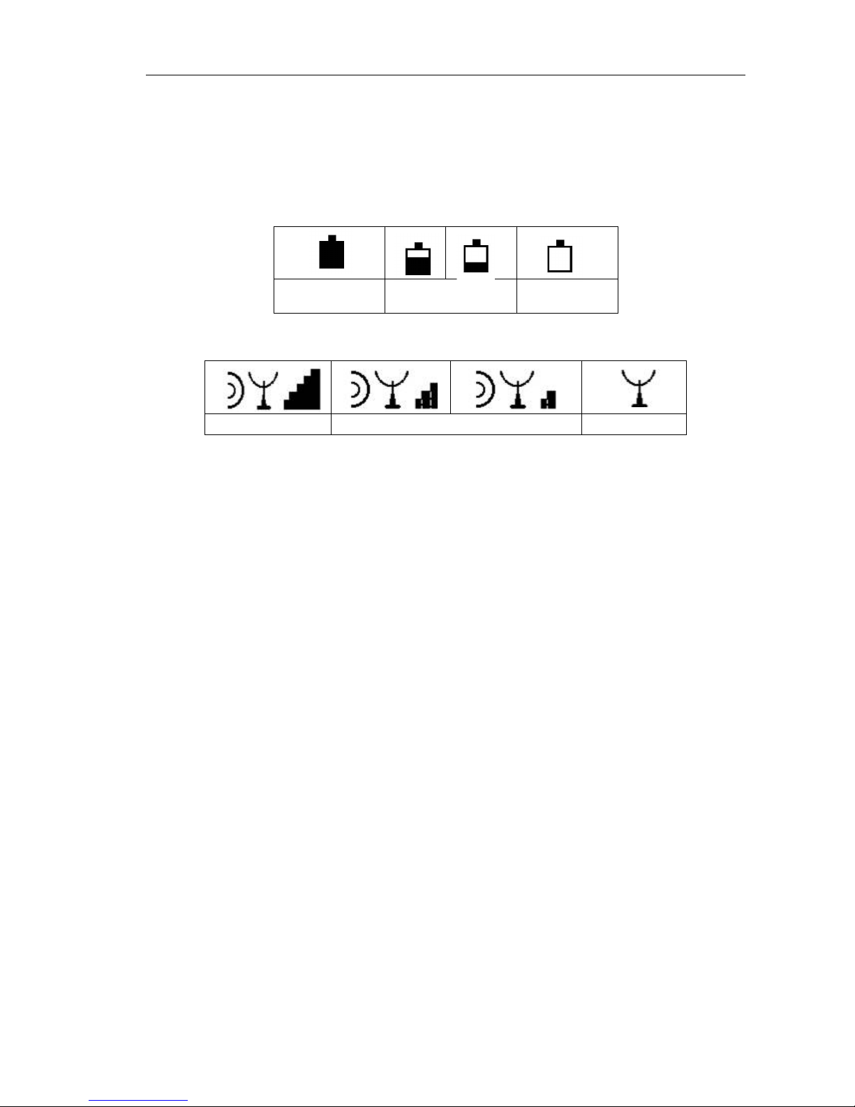
Symbols on the ISEsweat® screen (top right)
Battery:
Charged
battery
Battery at
medium/low level
Flat battery
Radio Coverage:
Correct coverage
Coverage at medium/low level No coverage
Page 50

ISEsweat
- User’s Manual 50
ANNEX F Regulations
Page 51
ISEsweat
- User’s Manual 51
This product has been designed and manufactured in accordance with U.S. and
European regulatory requirements as out-lined below. Modifications made to this
product that are not expressly approved in writing by the manufacturer will void the
user’s authority to operate this product, previously issued factory approvals, and the
user’s rights under the warranty.
All quality control requirements and testing should be performed in conformance with
local, state and/or federal regulations or requirements.
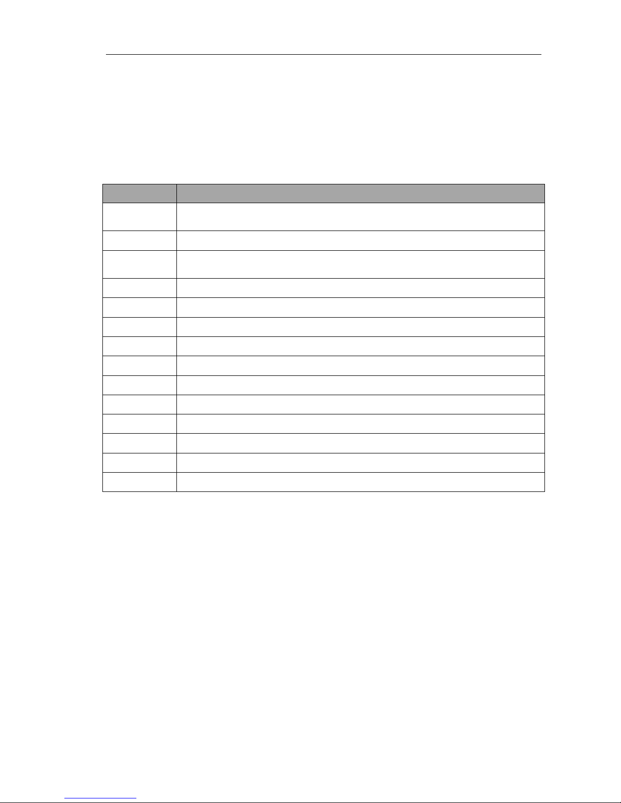
Regulation
Description
EN 60601
General Requirements for electrical medical equipments in relation to
Electromagnetical compatibility and Electrical security.
ISO 7000
Graphic symbols for equipment use.
ISO 1258
Guidelines for electrical medical equipment development and instructions
use.
ISO 1000
Units
EN 980
Symbols + EN 20780
ISO 8601
Date representation
ISO 639-1
Language representation codes
ISO 15225
Nomenclature
ENTR 15133
General terminology
EN 1041
Information supplied by the manufacturer of Medical Devices
EN 2860
Date format
EN 2078
Packages and graphic symbols on manipulation.
21CFR820
Quality system regulation
CLSI C34-A3
CLSI Guideline Sweat Testing
Page 52

ISEsweat
- User’s Manual 52
Federal Communications Commission (FCC) Statement
15.21
You are cautioned that changes or modifications not expressly approved by the part
responsible for compliance could void the user’s authority to operate the equipment.
15.105(b)
This equipment has been tested and found to comply with the limits for a Class B
digital device, pursuant to part 15 of the FCC rules. These limits are designed to
provide reasonable protection against harmful interference in a residential
installation. This equipment generates, uses and can radiate radio frequency energy
and, if not installed and used in accordance with the instructions, may cause harmful
interference to radio communications. However, there is no guarantee that
interference will not occur in a particular installation. If this equipment does cause
harmful interference to radio or television reception, which can be determined by
turning the equipment off and on, the user is encouraged to try to correct the
interference by one or more of the following measures:
-Reorient or relocate the receiving antenna.
-Increase the separation between the equipment and receiver.
-Connect the equipment into an outlet on a circuit different from that to which the
receiver is connected.
-Consult the dealer or an experienced radio/TV technician for help.
This device complies with Part 15 of the FCC Rules. Operation is subject to the
following two conditions:
1) this device may not cause harmful interference and
2) this device must accept any interference received, including interference that may
cause undesired operation of the device.
Page 53

ANNEX G Manufacturer declaration
Page 54
ISEsweat
- User’s Manual 54
This product complies with the EN/IEC 60601-1-2:2008 regulation.
CAUTION: Use of accessories, sensor cards and cables that are not specific for ISEsweat®
can lead to increased electromagnetic emissions and greater susceptiblility to interference.
This can also cause inexact readings.
The Power supply included with the device is medical grade. If the user changes the power
supply, you must make sure that the new one is also of medical grade.
Wires and cords comply with these regulations:
• RF emissions, EN 55011, Class B/Group 1
• EN 60601-1-2; 2008
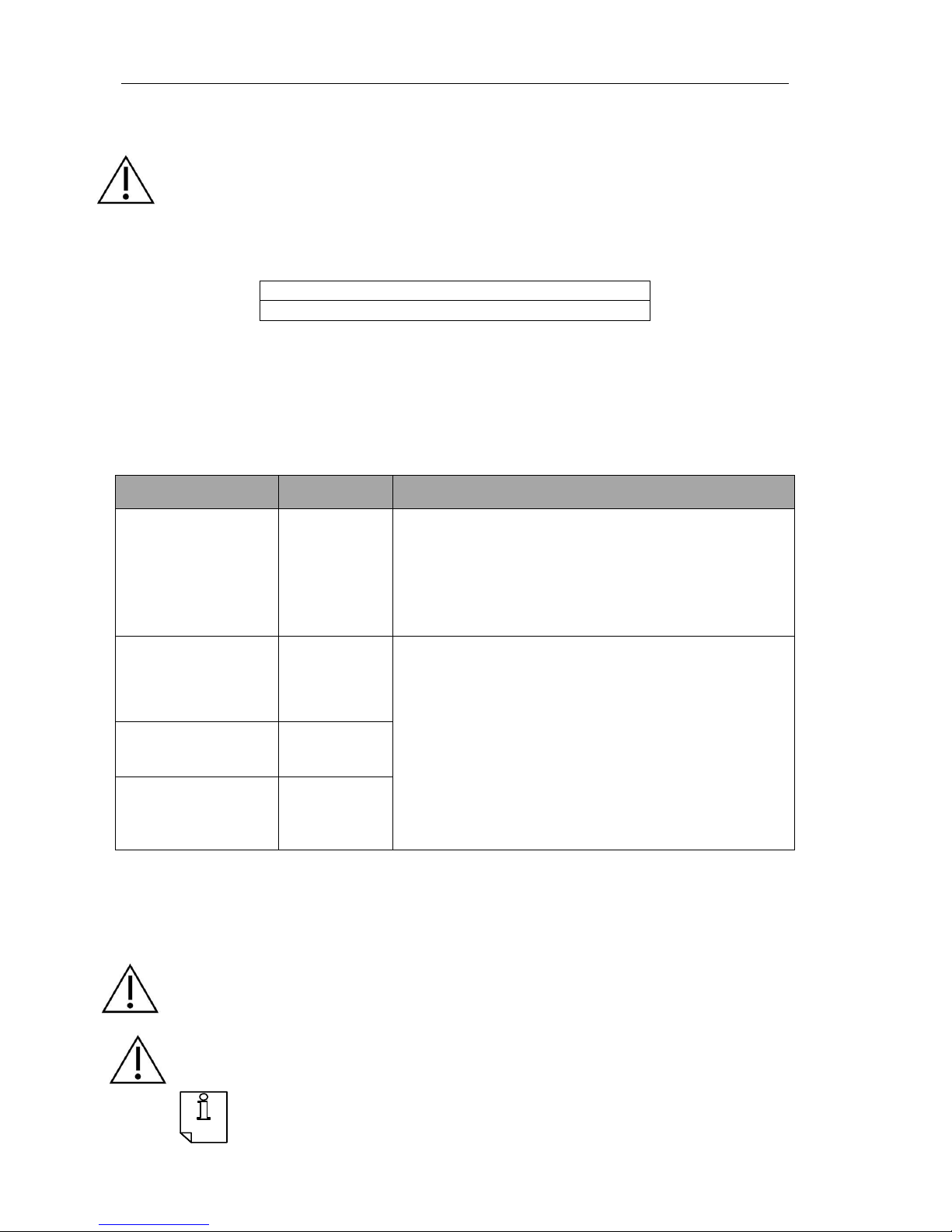
Table 10: Wire and cords regulations
The ISEsweat® is designed for use in the electromagnetic environment described below. The
user must ensure that it is used in such an environment.
Electromagnetical emissions.
Emission test Performance Electromagnetical environment - guideline
RF Emissions
CISPR 11
(IEC 55011 and
IEC 55022)
Group 1
The ISEsweat® only uses radiofrequency power for
communication within a room. Its RF emissions are very
low and there is little probability of them causing
interference with other nearby electronic equipment.
RF Emissions
CISPR 11
(IEC 55011 and
IEC 55022)
B Class
The ISEsweat® can be used in public places, including
diagnostic establishments and places with direct access to
the public and in buildings used for domestic purposes.
Harmonic emissions
IEC 61000-3-2
A Class
Tension fluctuation
/blinking emissions
IEC 61000-3-3
Pass
Table 11: Electromagnetical emissions
Electromagnetical immunity.
WARNING: The back of the equipment base unit, where the connections are
made, must not be touched when the equipment is ON.
WARNING: The remote card connector due its extreme sensitivity could occasionally stop
the measurement or cause a reset while the remote unit is being positioned. If this happens,
reset the base and remote units and start the analysis again.
Page 55
ISEsweat
- User’s Manual 55
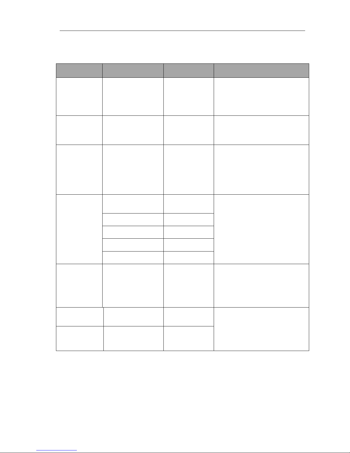
NOTE: U Var % is the network CA tension before applying the test level (230 V /
50 Hz).
Susceptability
test
IEC Test level
60601
Performance
level
Electromagnetical environment
- Guideline
Electrostatic
discharge
(ESD)
IEC 61000-4-2
Direct contact of ±6 kV
Airborne of ±8 kV
Pass
Floor must be made of wood,
concrete or wooden tiles.
If it is covered by any synthetic
material, relative humidity must be
30% minimum.
Transitional
Fast/Burst
IEC 61000-4-4
Power lines of ±2 kV Pass
Power network supply must be the
usual one in a hospital or commercial
environment.
Surge
IEC 61000-4-5
Differential mode
(symmetrical
application)
of ±2 kV
Ordinary mode
(asymmetrical
application)
of ±1 kV
Pass
Power network supply must be the
usual one in a hospital or commercial
environment.
Voltage drops,
micro
interruptions and
inline voltage
variations
IEC 61000-4-11
>95 U Var. % for 10
milliseconds
Pass
Power network supply must be the
usual one in a hospital or commercial
environment. ISEsweat® must run the
program again after interruption
60 U Var. % for 100
milliseconds
Pass
70 U VAr. % for 500
milliseconds
Pass
>95 U Var. % for 5000
milliseconds
Pass
>95 U Var. % for 20
milliseconds
Pass
Magnetic field
associated with
the supply
frequency
(50/60 Hz)
IEC 61000-4-8
3 A/m Pass
Magnetic fields associated with the
supply frequency must have similar
features to a usual hospital or
commercial environment.
Conductive RF
IEC 61000-4-6
3 V rms
150 kHZ to 80 MHz
3 V rms
Portable and radiofrequency
communication equipment must not
be used near the ISE Sweat and its
cables. For the test, the distance
between the RF source and the
instrument being tested must not be
less than 3m.
Radiated RF
IEC 61000-4-3
3 V/m
80 MHz to 2,5 GHz
3 V/m
Table 12: Electromagnetical susceptability
Page 56

ISEsweat
- User’s Manual 56
ANNEX H Warranty
Page 57

TECIL,S.A. guarantees to repair or replace free of charge parts and pieces with working
failures due to manufacturing causes for 24 months after delivery, as well as providing all
labour needed to repair them.
All parts that have been replaced when repairing the unit will automatically become
property of TECIL,S.A.
Damage caused by improper use or by non-compliance with the operating
instructions will result in the invalidation of the warranty.
Interventions from persons other than TECIL,S.A. authorized specialists may lead to
invalidity of warranty.
Page 58

ISEsweat
- User’s Manual 58
ANNEX I History Sweat Test
Page 59

Although several techniques have been created for the collection and measurement of sweat
electrolytes, the most reliable test is based on the pilocarpine iontophoresis technique
described by Gibson & Cooke in 1959, which is still considered to be the gold standard for
CF diagnosis specially in babies.
However, this is a complex combination of techniques that requires weigh sweat using an
analytical scale, elution and undergo biochemical analysis of electrolytes. According to this
method, it is necessary to collect at least 70 mg of sweat.
In order to make the test simpler, many labs have been using alternative methods. One of
these methods includes the use of the device Macroduct® – a sweat collection system,
through which sweat is collected into a plastic coil after stimulation by pilocarpine
iontophoresis. Weighting is thus eliminated. The sweat can be taken from the coil and its
ionic composition can be later analyzed using the usual biochemical techniques, or it may be
immediately placed in the conductivity analyzer – Sweat- Chek – Wescor, which will quickly
provide the equivalent values of sweat sodium chloride (NaCl) in mmol/L.
Because of methodological problems , confirmation or rejection of the diagnosis of CF should
only be based on the results of quantitative pilocarpine iontophoresis sweat chloride
described in the specific guidelines. Those guidelines consider not acceptable for CF
diagnostic the direct reading in situ test using Orion ISE or older electrical conductivity
measurements, or measurements or osmolality or sodium. Conductivity instruments
designed specifically for use with microbore tubing collector was approved by CFF as
screening method but only for use outside accredited Cystic Fibrosis Care Centers.
In 2010 Tecil introduced ISEsweat®, a new method for direct sweat Chloride measurement
who eliminates all intrinsic sources of error associated to collection methods and with
microISE specifically designed for microsamples. ISEsweat gives the concentration of sweat
chloride independently of the sample quantity, that’s why there is no need to measure the
amount of sweat collected.
A multicentrical clinical trial made in 113 subjects and presented at the European Cystic
Fibrosis Society concluded that ISEsweat is a valid and safety new device for sweat chloride
concentration measurement. The results of this first clinical assay are very encouraging and
warrant further research with larger samples of patients, to confirm that the ISEsweat can
become a useful tool for the diagnosis of CF and even prove to be a reliable and more
convenient alternative method compared to the reference sweat test as approved by current
guidelines.
Page 60

ISEsweat
- User’s Manual 60
ANNEX J Reference
Page 61

1. Grosse, Scott D., Ph.D.; Boyle, Coleen A., Ph.D.; Botkin, Jeffrey R., M.D.;
Comeau, Anne Marie, Ph.D.; Rosenfeld, Margaret M.D.; Wilfond, Benjamin S.,
M.D.; Newborn Screening for Cystic Fibrosis. Morbidity and Mortality
Weekly Report (MMWR), October 15,2004 / Vol. 53 / No. RR-13.
2. Wagener, Jeffrey S., M.D.; Sontag, Marci K., M.S.; and Accurso, Frank J.,
M.D.; Newborn Screening for Cystic Fibrosis. Pediatrics 2003 / 15 : 309-
315.
3. Gibson, L.E.; Cooke, R.E.: “A test for concentration of electrolytes in
sweat in cystic fibrosis of the pancreas utilizing pilocarpine by
iontophoresis.” Pediatrics 1959. 23: 545 – 549.
4. National Committee for Clinical Laboratory Standars.: “Sweat testing:
sample collection and quantitative analysis; approved guideline.”
NCCLS document C34-A3 (ISBN I-56238-260-8). NCCLS,771 East Lancaster
Avenue, Villanova, Pennsylvania 19085, December 2009.
5. Augartern, A.; Hacham, S.; Kerem, E.; et al.: “The significance of Sweat
Cl/Na ratio in patients with borderline Sweat test.” Pediatr. Pulmonol.
1995. 20:369-71.
6. Grupo de Trabajo "Fibrosis Quística" SENP Protocolo de diagnóstico y
seguimiento de los enfermos con fibrosis quística. An Esp Pediatr 1999;
50: 625-634.
7. Javier Gonzalo-Ruiz, Roser Mas, Carmen de Haro , Enric Cabruja a ,Rafael
Camero, M. Asuncion Alonso-Lomillo, F. Javier Muñoz “Early determination
of cystic fibrosis by electrochemical chloride quantification in sweat”.
Biosensors and Bioelectronics 24 (2009) 1788–1791
8. R. Camero, S. Gartner, L. Suarez, C. Vázquez, M. Silvestre, Y. Montecino, B.
Matía, R. Passarell, A. Moreno, N. Cobos, Validation of ISEsweat: a new
device for the direct measurement of sweat chloride concentration (SCC)
for the diagnosis of cystic fibrosis, Journal of Cystic Fibrosis, Volume 9,
Supplement 1, June 2010, Page S12, ISSN 1569-1993, 10.1016/S15691993(10)60046-X.
(http://www.sciencedirect.com/science/article/pii/S156919931060046X)
9. K.P. Foote, S. Struthers, H. Barbour
“Report of a new and important cause of falsely positive sweat test”
Journal of Cystic Fibrosis, Volume 7, Supplement 2, June 2008, Page S10
 Loading...