

Page 1
08/16
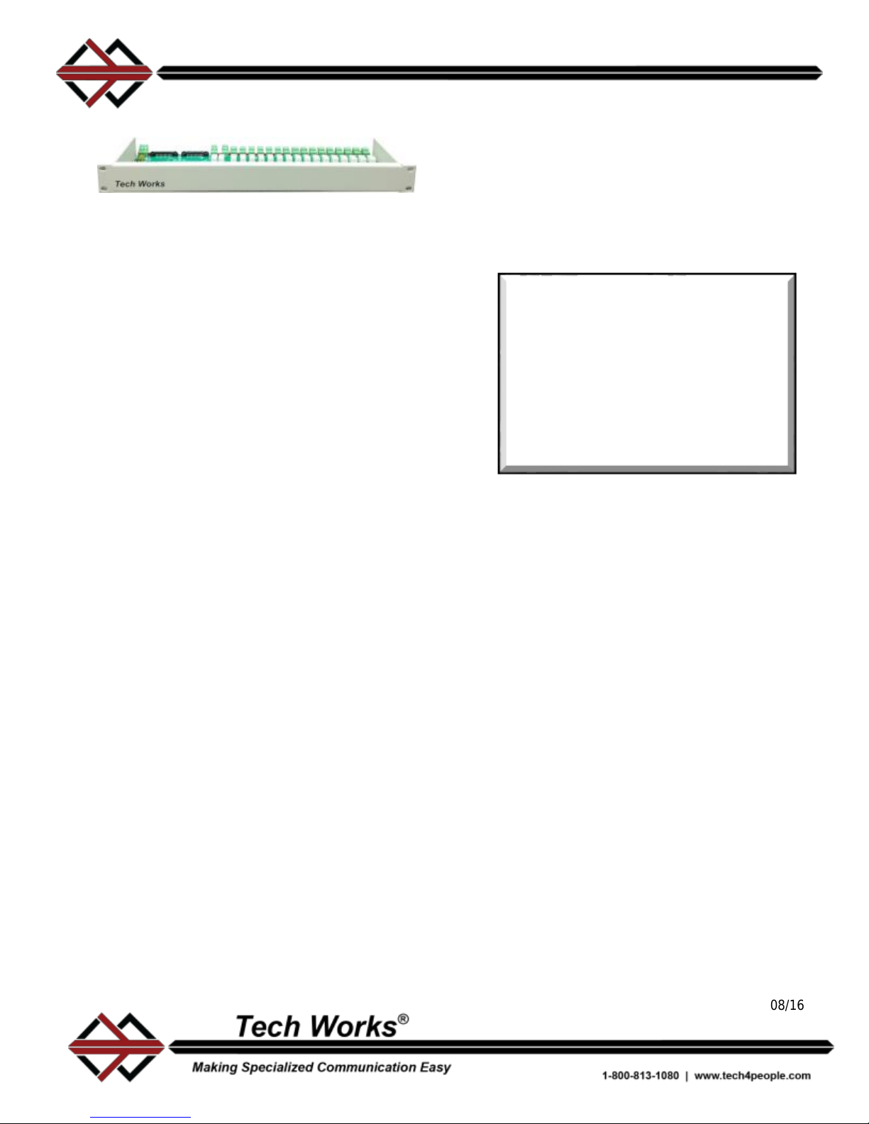
The ICR-116 Intercom Switching Relays are
ruggedized intercom panels for use in harsh
environments, such as correctional facilities.
The ICR-116 provides high quality audio
communication with complete flexible control.
The unit has connections for 16 remote
intercom Stations, each with their own Speaker
and Call-in Switch. The Call-In and Relay
Control connections are each 24-pin ribbon
connectors.
A jumper option supports either Sinking or
Sourcing Relay Drivers. Another Jumper Option
allows the Call-in switches to be referenced to
the Logic or Relay Power Source.
For convenience, all of the ICR-116
connections are connectorized. Remote
Stations connect via 4-pin 0.1” Spring Cage
Euro-Style Barrier Strips. Connections for
Power, Intercom Amplifier, and Paging
Amplifier, are Screw Terminal Euro-Style
Barrier Strips.
Associated with each Station Selection Relay is
a Station Status Indicator. The Station
Indicators show the Technician which relay or
relays are active. The indicators are intuitive,
and easily interpreted. Each Station Indicator is
either Off or On. When an Indicator is Off, there
is no activity with that station. When an
Indicator is On, that Station is selected for
Communication.
Another product, the ICR-116EX, has a multipin connector on the opposite side of the PCB
for access to the normally closed relay
contacts. By using the “Back Contacts”, multiple
masters or priority switching can be achieved.
In applications where a more powerful Paging
Amplifier is required, a Paging Relay(s)
connects Selected Station(s) to a Paging
Amplifier Output, such as the Tech Works PA-
402.
ICR-116
Intercom Relay 16 Channel
Installation Manual
Specifications:
16 Double Pole/Double Throw station
audio relays
2 Double Pole/Double Throw page
audio relays
Relay Current 15MA
Maximum Station Audio Power; 50
Watts @ 25 Volts
Maximum Paging Audio Power; 100
Watts @ 25 Volts
Color:
Grey powder coated metal
chassis
Power:
24VDC, 0.3A, (Power Supply
not included)
Weight:
5 lbs.
Dimensions:
19” W X 1.75” H X 8.6”D
Optional Accessories:
ICA-202D
Dual Channel Intercom Amplifier
DODC
Detention Operator Desk Console
PA-402
Paging Amplifier
ICR-44
Intercom Routing Relays
RC-24-10
Ribbon Cables
RC-BB-24
Screw Terminal Breakout Boards
BENEFITS
Designed Specifically for
Corrections
High Quality Audio
Options Designed for
Corrections Industry
Engineered & Built in U.S.A.
36-month Limited Warranty
Page 2
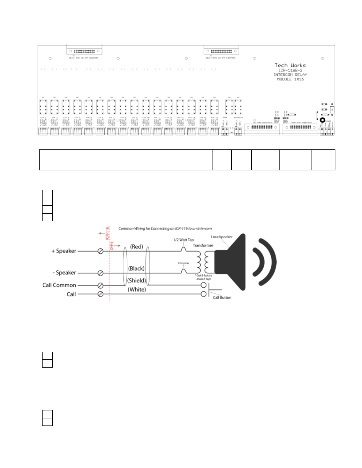
Connectors and Function:
Station Connectors (1-16)
Page
Amp
IC
Amp
Relay
Select
Call
Input
Power
Station Connectors, 1-16, Euro-Style Barrier Strips (Pin 1, Left):
1
SPKR (+)
2
SPKR (-)
3
CALL COMMON / SHIELD
4
CALL SWITCH
SPKR connect to the Wiper of the Station Relays
CALL COMMONs tie together, and go to the CALL SIGNAL CONNECTOR
Page Connector, Euro-Style Barrier Strip, (Pin 1, Left):
1
Amplifier OUT(+)
2
Amplifier OUT (-)
The Paging Amplifier is connected to the selected Stations when the Page Relay is selected
Intercom Amplifier Connector, Euro-Style Barrier Strip, (Pin 1, Left):
1
Remote SPKR (+)
2
Remote SPKR (-)
The Intercom Amplifier is connected to Stations when their Respective Station Relay is Selected
Page 3
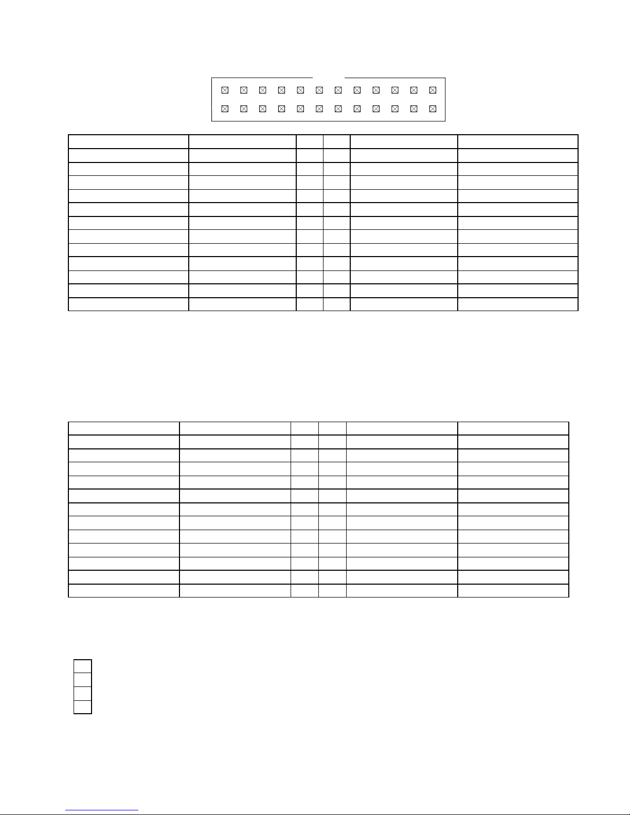
Relay Select Connector, 24 Pin Ribbon Wire Header, (Pin 1, Top-Right):
13579
2
46
8
10
12
14
16
18
20
22
24
11
13
1517192123
Ribbon Cable Color
Ribbon Cable Color
Yellow
SELECT-1
1 2 SELECT-2
Orange
Red
SELECT-3
3 4 SELECT-4
Brown
Black
SELECT-5
5 6 SELECT-6
White
Gray
SELECT-7
7 8 SELECT-8
Violet
Blue
SELECT-9
9
10
SELECT-10
Green
Yellow
SELECT-11
11
12
SELECT-12
Orange
Red
SELECT-13
13
14
SELECT-14
Brown
Black
SELECT-15
15
16
SELECT-16
White
Gray
SELECT-PAGE
17
18
N/C
Violet
Blue
N/C
19
20
N/C
Green
Yellow
(Return) -24 VDC
21
22
-24 VDC (Return)
Orange
Red
(Return) +24 VDC
23
24
+24 VDC (Return)
Brown
*NOTE: For Source Drivers, “-24 VDC” is the circuit Return
For Sink Drivers, “+24 VDC” is the circuit Return
The Intercom Amplifier is connected to Stations when their Respective Station Relay is Selected.
The Paging Amplifier is connected to Unselected Stations when the Call Relay is energized.
Call Signal Connector, 24 Pin Ribbon Wire Header (Pin 1, Top-Right):
Ribbon Cable Color
Ribbon Cable Color
Yellow
CALL-1
1 2 CALL-2
Orange
Red
CALL-3
3 4 CALL-4
Brown
Black
CALL-5
5 6 CALL-6
White
Gray
CALL-7
7 8 CALL-8
Violet
Blue
CALL-9
9
10
CALL-10
Green
Yellow
CALL-11
11
12
CALL-12
Orange
Red
CALL-13
13
14
CALL-14
Brown
Black
CALL-15
15
16
CALL-16
White
Gray
N/C
17
18
N/C
Violet
Blue
N/C
19
20
N/C
Green
Yellow
CALL COMMON
21
22
CALL COMMON
Orange
Red
+24 VDC
23
24
+24 VDC
Brown
The CALL-X signal is connected to CALL COMMON, when its respective switch is closed
Power Connectors, Euro-Style Barrier Strip, (Pin 1, Left):
1
+24 VDC input (Return)
2
-24 VDC input (Return)
3
CALL COMMON
4
CHASSIS
*NOTE: For Source Drivers, “-24 VDC” is the circuit Return
For Sink Drivers, “+24 VDC” is the circuit Return
See “Jumper Options” for Details
Page 4
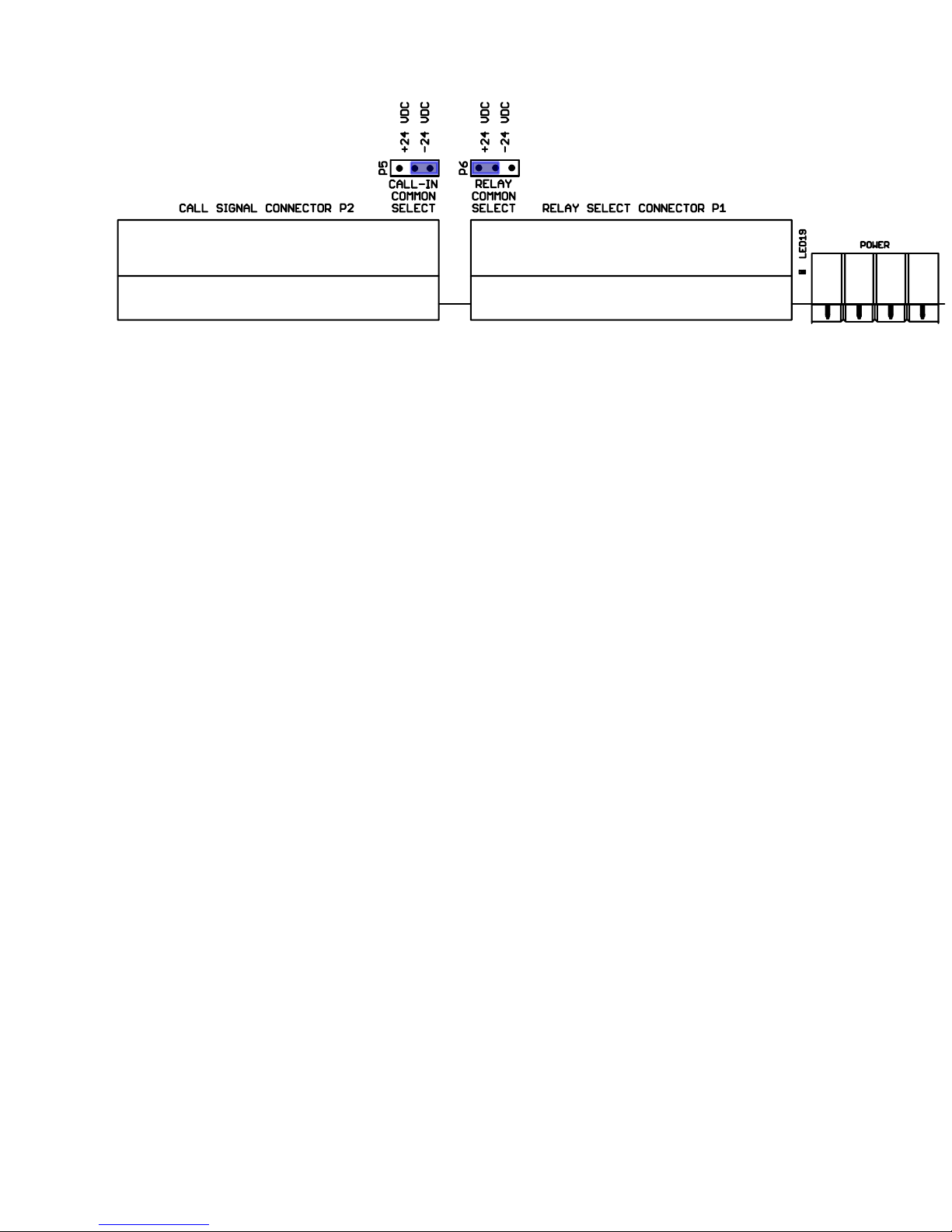
Jumper Options:
The ICR-116 has two sets of Configuration Jumpers to accommodate various PLC Control Options.
Both sides of the Relay Power Supply are connected to the ICR-116. When the Power Supply is
connected properly, the Power Indication should be lighted Green.
CALL COMMON SELECT:
CALL COMMON is connected to all Station Connectors - Pin 4 and Pin 3 of the Power Connector.
The CALL COMMON may be referenced to either Power Supply rail, allowed to float, or referenced to
an external “Common”.
In most Installations, the CALL COMMON is referenced to the Relay Power Supply. For Convenience
the Jumper may be in either Position:
+24 VDC CALL COMMON is connected to the +24 VDC Relay Power Supply Rail
-24 VDC CALL COMMON is connected to the -24 VDC Relay Power Supply Rail
If the CALL COMMON Jumper is removed, the CALL COMMON pin on the POWER Connector floats
and may reference to any source.
RELAY COMMON SELECT:
The Relay SELECT-X lines may be reference to either Rail of the Relay Power Supply
+24 VDC Sinking Drivers, Relay indicators will light Green when a relay is energized
-24 VDC Sourcing Drivers, Relay indicators will light Red when a relay is energized
NOTES:
CALL COMMON is connected to CHASSIS with a 1MEG-Ohm resistor
-24 VDC is connected to CHASSIS with another 1MEG-Ohm resistor
The +24VDC has a 500MA Resettable Fuse for the Relays
The +24VDC has another 500MA Resettable Fuse for the SELECT & CALL Connectors
Page 5

Application Notes:
Please refer to the schematic for a better understanding of this section.
Refer to the ICA-202D Intercom Amplifier installation manual, (For application examples see pages
24 & 25). Refer to the PA-402 Power Amplifier installation manual.
The ICR-116 is suitable for any Intercom System requiring Multiple Station Selection. However, these
examples refer to use with other Tech Works products.
Each Station consists of a Speaker, which is also used as a Microphone (Half-Duplex Operation)
and a Call-In Switch.
Stations are selected by energizing that Stations Relay
Some control systems have Sinking Relay Drivers (Pull to Ground), while other control systems have
Sourcing Relay Drivers (Pull to +24Volts). The ICR-116 accommodates either type driver (See
Jumper Options).
When the Relay is energized, the Intercom Amplifier is connected to that Station’s Speaker.
When a Relay is not energized, the Station Speaker is terminated by two 200-Ohm resistors tied to
COMMON. The Termination serves two purposes; reducing crosstalk, bleeding off static electricity.
When listening normally, only one relay is energized at a time. However, during (Zone) Paging, many
or all relays may be energized simultaneously.
When stations are selected, good design practice sequences the Intercom Amplifier to avoid
listening Pops. The ICA-202 has a Mute input, which simplifies this implementation. The selection
sequence is Mute Intercom, Select Station, wait ~100mS, Un-Mute Intercom. The de-selection
sequence is Mute Intercom, De-Select Station. The new selection sequence is Mute Intercom, Select
new Station, wait ~100mS, Un-Mute Intercom.
Station Call-in Switches have a Common Return
The Call-In Switches are separate circuits from the audio pathways. Some control systems Reference
the Call-In Switched to the Relay Power Supply Negative Rail. Some control systems Reference the
Call-In Switched to the Relay Power Supply Positive Rail. Some control systems Reference the CallIn Switched to a Logic (PLC) reference. The ICR-116B accommodates any type of reference (See
Jumper Options).
The Paging Relay(s) may be used in systems where the Intercom Amplifier has insufficient
Power
When the Paging Relay(s) are energized, selected Stations are connected to the Paging Amplifier
output. This is especially easy to implement using Tech Works Intercom Products. The ICA-202D
“Paging Audio Output” connects to the PA-402 Paging Amplifier “Paging Audio Input”. The ICA-202D
and PA-402 Page Logic control inputs are tied together. The PLC Energizes the Page & Station
Relays, and then pulls the Page Logic inputs to Common.
Page 6
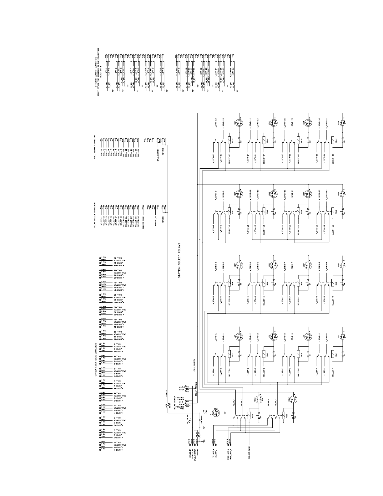
Schematic Diagram:
ICR-116B-1 SCHEMATIC DIAGRAM
Page 7
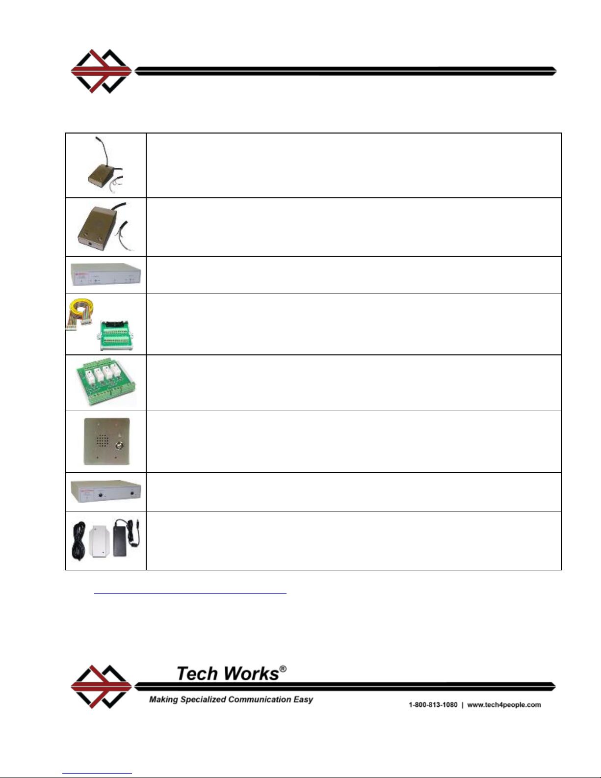
System Accessories
DODC-1 - Operator Desk Console - This all steel console with brushed stainless
steel faceplate and vandal resistant push buttons has an epoxy finished cold rolled
steel base, a permanently attached gooseneck microphone provides clear, high
quality page and intercom talk while a vandal resistant 3 inch speaker provides clear
listening.
DODC-2 - Operator Desk Console - This all steel console with brushed stainless
steel faceplate and vandal resistant push buttons has an epoxy finished cold rolled
steel base, a hidden flush mount microphone provides clear, high quality page and
intercom talk while a vandal resistant 3 inch speaker provides clear listening.
ICA-202D - Intercom Amplifier - 20 watts of clean audio power at 25-Volts it can do
both the Intercom and most Paging functions. Automatic Level Control (ALC)
assures the speaker level remains constant over a wide dynamic input range.
RC-24-* and RC-BB-24 - 24-pin Ribbon Cable and Breakout Board - Designed to
connect our Tech Works Intercom Relay panels with digital control equipment. The
RC-24-* is available in various lengths (10 feet standard). The breakout board has
mounting tabs for screw mounting wherever convenient.
ICR-44 - Intercom Relay Module 4x4 - Tech Works makes a variety of intercom
Relay modules for routing audio and calls in signals. The ICR-44 is a snap track
mount 4 relay assembly designed to allow multiple master audio routing by a PLC.
VPSS - Vandal Proof Speaker Station - a call-in station with integral
speaker/micro- phone and momentary, normally open, push-to-call button. The
faceplate is a 2 gang electric box mount, 12 gage, brushed stainless steel with
security screens mounted between the faceplate and the loudspeaker. Tamper-
resistant hardware is included.
PA-402 Paging Amplifier - designed to add Power to the ICA-202D. It delivers 40
Watts to 25 Volts loads at very low noise and distortion. Perfect for Prisons or
Security applications when covering large areas or All Page.
PS2437A - Power Supply - 24V DC @ 3.7 Amps - is a regulated computer grade
power supply. This unit is UL listed and includes a 6-foot removable power cord with
a North American standard Edison connector. Includes wall mount bracket.
Visit www.tech4people.com/catalog/products for a catalog of all Tech Works products and
accessories. If you don’t see something that you need be sure to contact us, we regularly fill special
request orders.
06/2016
Page 8

This Page Has Been Intentionally Left Blank
 Loading...