

CI-MSI-22
QUICK REFERENCE GUIDE
The MSI-22 is a Microphone and Speaker Interface for our Collaborative Intercom family of products.
The can be two Microphones (One from the Microphone Input; one from the PA-BUSS Input using a PA-MI-1)
Two Speaker outputs (One from the Speaker Output; one from the PA-BUSS output using a AS-1 or PA-402)
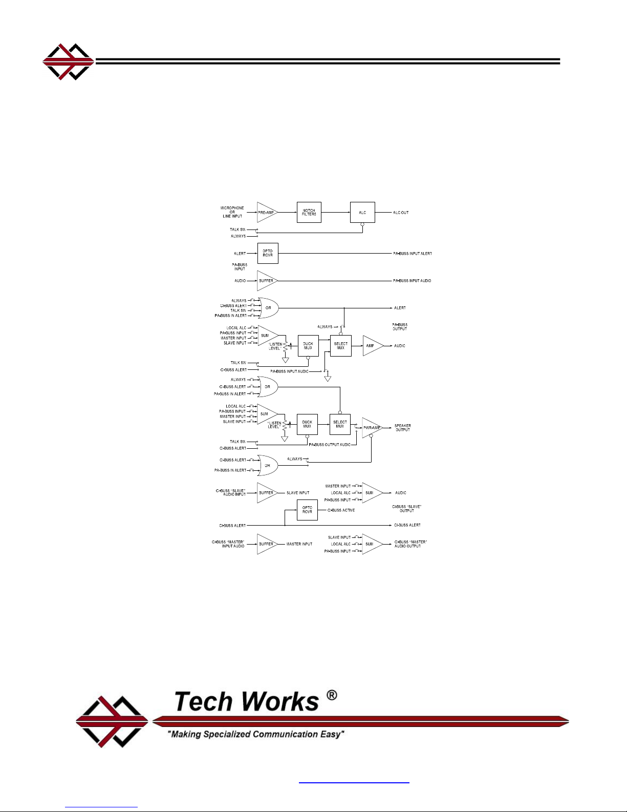
Basic Microphone / Speaker Interface Block Diagram (Transformers not shown for clarity)
Each input can be routed to an output or all outputs by placing routing jumpers inside the unit as desired.
The CI-BUSS interface performs the same function for additional units. The Microphone is processed
with ALC to be of constant level and passed to other Units in both directions as selected.
The ALC has an indicator for the Threshold of Limiting.
This indicator also serves as a setup indicator for adjusting the Microphone level.
Tech Works, Inc., 7430 Eastgate Road, Suite 130, Henderson, NV 89011
Direct Line: 702-846-1080 Toll Free: 1-800-813-1080
Web site www.tech4people.com 6/17

Front Controls and Indicators:
CI-MSI-22
COLLABO RATIVE INTER COM
MICROPH ONE / SPEAK ER
INTERFA CE
POWER
CI-BUSS
PA-BUSS
ALERT
INPUT
ACTIVE
ACTIVE
MICROPHONE
TALK
LEVEL
GAIN
LO HI
PA-BU SS
OUTPU T
LEVEL LEVEL
ON
SPEAKERNOTCH
ON
Power indicator: Green, when operating Normally
CI-BUSS, ALERT Active Indicator: Green, when the Operator Microphone is Active
PA-BUSS Input, ALERT Indicator: Green, when the PA-BUSS Input is Active
Microphone Gain: 16 Position Rotary Switch, factory set to 8, 3dB/Step, 45dB Range
Talk Level Indicator: Green, low input level; Green, flashing to Red, Normal Operation, with Local
Microphone, and ALC is active
Notch Filter: ‘LO’ Band Notch Filter trimpot, 250 to 1000Hz‘; HI’ Band Notch Filter trimpot, 750Hz to 3000Hz
PA-BUSS Output: Level Control trimpot; ON Indicator: Green, when the PA-BUS is ON
Speaker Output: Level Control trimpot; ON Indicator: Green, when the Speaker Amplifier is ON
NOTE: The Microphone Gain control is for setup; once set, it should not be touched by the User
Rear Connections:
CI-BUSS
TALK
COMMON
MIC (-)
SPKR (-)
SPKR (+)
MIC (+)
CALL-SW (+)
MASTER
CALL-SW (-)
CI-BUSS
SLAVE
PA-BUSS
INPUT
PA-BUSS
OUTPUT
CI-MSI-22
24VDC – 1.5 A
Tech W orks * YO RBA LIN DA * CA * 1-800 -813-1080 * WW W.TECH4PEOP LE.COM
Speaker Output: 25-Volts Maximum, 10-Watts Maximum; Two Position Euro-Style Barrier Strip: Speaker (+/-
)
Microphone Input: Four Position Euro-Style Barrier Strip: Universal Microphone/Line Input (+/-);
Shield/Switch Common; Talk Switch (N.O.)
Selectable Equalization - 3 settings optimized for voice communication
Selectable Phantom Power (22 Volts, Short Circuit Protected)
Configured for a Microphone Level Input: 2000 Ohms Balanced, -75dBm or -60dBm (Selectable)
minimum input (Balanced) for full rated output
Configured for a Line Level Input: 2000 Ohms Balanced, 1000 Ohms Unbalanced, Balanced input 35dBm to +5dB or -20dBm to +20dB Accommodation range (Selectable), Un-Balanced Input -30dBm
to +10dB or -10dBm to +20dB Accommodation range (Selectable)
Call Switch: Two Position Euro-Style Barrier Strip: Call Switch (+/-), (N.O.)
Call Switch must Float W.R.T. Common
CI-BUSS, “Master” Connector, RJ-45
CI-BUSS, “Slave” Connector, RJ-45
PA-BUSS, Input Connector, RJ-45, Optionally Powered for a CI-MI-1
PA-BUSS, Output Connector, RJ-45, Always Powered for an AS-1, 23 Volts @ 350MA Maximum
Power Connectors: (Two) - 3.5mm Barrel Connectors
Chassis: Knurled nut, Earth Ground
The Chassis is connected to Circuit Common through a 1-Meg-Ohm resistor
Page 2 of 4

Initial Adjustments:
There are both Input and Output Controls with associated Indicators
When the Indicators are green the associated control is enabled
The Audio may be 'Keyed' depending on the Configuration and system setup
Only attempt adjustments if the associated indicator is lighted green!
The CI-BUSS uses a standard audio level of ~0dBm RMS
The Digital Rotary Switch (3dB/Step) is used to set Microphone Gain
The nominal Microphone gain is ~6dB, or less, into limiting
Microphone Gain is always setup first
Initially, the Output level controls should be set to minimum (No Output)
Limiter Setup with a Microphone:
Always do first
Provide a normal input to the Microphone, or Line input
Insure the Microphone is Keyed, the indicator is Green
Advance the “Microphone Gain”, from “0” until the Talk Level indicator just flashes red
Advance the “Microphone Gain” no more than two clicks (6dB into limiting)
Monitor/Communications and Speaker setup:
Assure there is an audio input
With normal audio input levels, with Inputs and outputs keyed (Output Indicator Green)
Set the Speaker Listening Level
See the PA-BUSS Section for Monitor/Communications Output Adjustments
Notch Filter Setup: Do after initial setup
The factory settings are: LO, fully CCW, HI, Fully CW; the Notch Filters are essentially disabled
Notch Filters can greatly reduce feedback; however they cannot make up for poor acoustic isolation
There are two distinct primary resonance modes in most installations. One is room resonance; one mode is
most prevalent, such as floor to ceiling resonance. This frequency is usually on the order of a few hundred
cycles. The second mode is the distance of the microphone from a near object. This frequency is much higher
near 1000Hz. The MSI-22 incorporates two filters in tandem, one a low Band Filter 250Hz to 1000Hz, and the
other a High band Filter 750Hz to 3000Hz
Adjust the Notch Filters one at a time. Increase the Microphone Gain Control until feedback occurs.
Make a rough determination of the frequency (or measure the frequency with a counter).
If the feedback is below ~800Hz, adjust the ‘Lo Notch’ until feedback ceases. If the feedback is above
~800Hz, adjust the ‘Hi Notch’ until feedback ceases. (This is a 20-turn pot so it is best to start from one
extreme, and slowly turn the pot in the other direction
Increase the Microphone Gain Control until feedback occurs again, if it is at the same frequency; try finely
adjusting the same filter to see if the feedback can be eliminated. If the frequency is different, and in the other
range not already tuned, repeat the steps above
If only one Notch Filter is required, the other filter should be set at the extreme of its range.
Fully CCW (lowest frequency) for the LO filter, and fully CW ( highest frequency) for the HI filter.
After the Notch Filters are adjusted, redo the initial adjustment above
Note:
Before making any adjustments assure there are audio Inputs and Outputs
All the associated indicators must be lighted green
Page 3 of 4
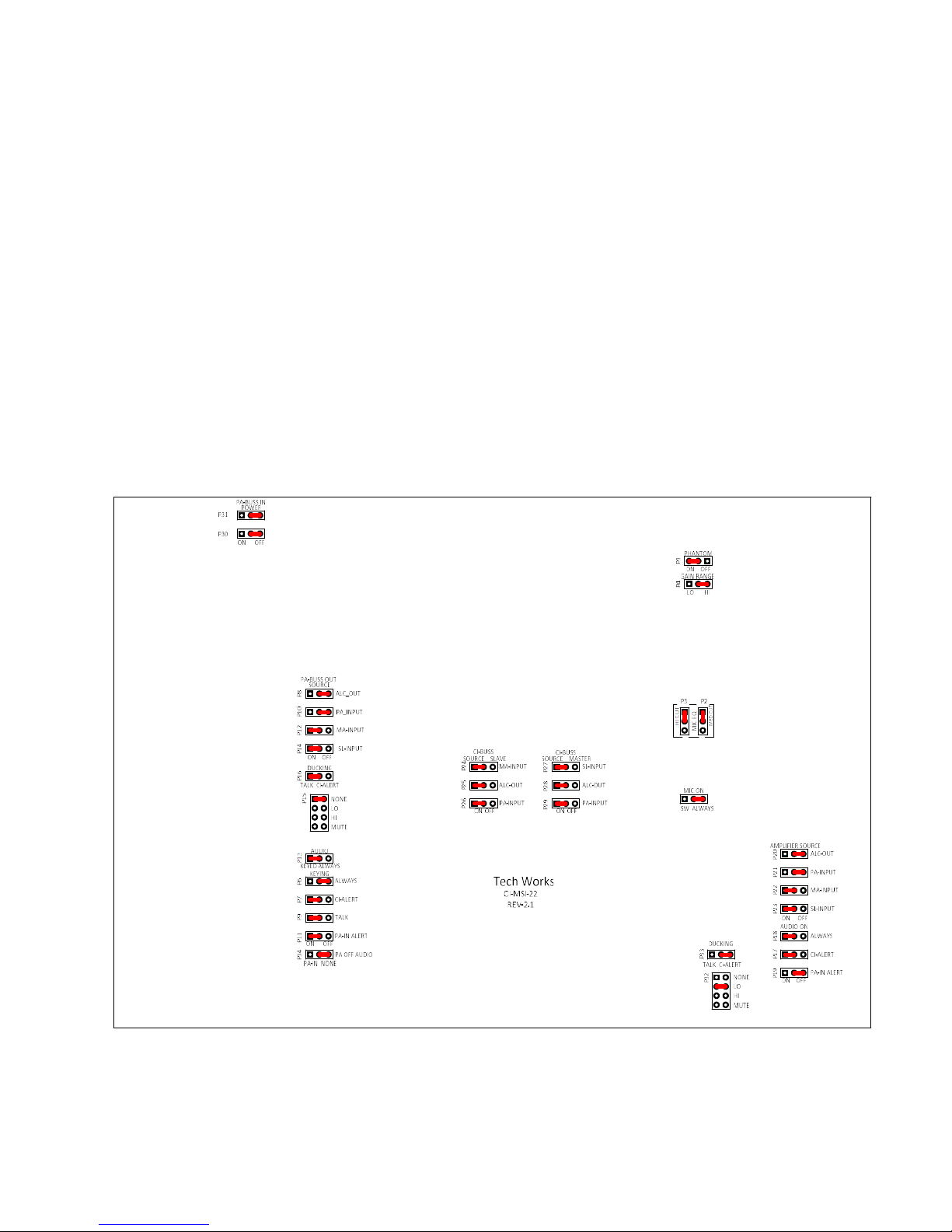
Configuration Options:
The MSI-22 is designed to accommodate many applications. For most applications the factory default
setting is sufficient. For ‘special’ applications a few jumpers may need to be moved. These Jumpers
determine how the MSI-22 interacts with other Components of the System
Before attempting a Configuration you should review the "BUSS Systems Guide" CI & PA, BUSS
sections
The MSI-22 consists of five Functional Modules:
Two Inputs; Local Microphone/Line Input; PA-BUSS Input
Two Outputs; PA-BUSS Monitor/Communications Output; Speaker Amplifier
CI-BUSS Interface
The Jumper Options determine how these Modules interact and function with each other
The "Standard Configuration" is a Remote (Single Location) for use with an Operator Console
This is a Remote (Single Location) for use with an Operator Console, CI-ODC
The Power Amplifier, is used for a Procedure Room Ceiling Speaker
The PA-OUT, is used as Procedure Room Communications
The PA-IN, may or may not be used for another Microphone
The CI-BUSS may be used with other Interfaces, such as a CI-HSI-41
Jumper Options
Page 4 of 4
 Loading...