

QUICK START GUIDE FOR ACCESS
CONTROL BOARDS
D Series One Door TCP/IP Web Server Controller
Model: AB-D1EWN

Table of Contents
3 01- Introduction
4 02 - Overview
4 02.1 - Package Contents
4 02.2 - Installation Requirements
5 02.3 - Network Overview
6 02.4 - Board Overview
7 03 - LED’s
7 03.1 - Main Board LED’s
7 03.2 - LAN LED’s
8 04 - Power
8 04.1 - Powering the Board
8 04.2 - Power Boxes
9 05 - Door Connections
9 05.1 - Connecting a Reader
10 05.2 - Connect a Push-to-Exit
10 05.3 - Connecting Multiple Readers
11 05.4 - Attendance
11 05.5 - Anti-Passback
12 05.6 - Door Example
13 05.7 - Board Example
14 06 - Locks
14 06.1 - Connecting a Lock
15 06.2 - Connecting Multiple Locks
16 06.3 - Connecting Signal Wire
17 06.4 - Powering Locks with Same PWR Sup
18 06.5 - Powering Locks with Seperate PWR
19 06.6 - Nornally Open and Normally Closed
20 06.7 - Fail Safe Vs. Fail Secure
20 06.8 - Types of Locks
21 07 - Lan
21 08.1 - Connecting to the Network
22 08 - Extras
22 08.1 - Connecting a Siren, Buzzer, or Light
23 08.2 - Connecting a Push-to-Enter Button
23 08.3 - Connecting a Request-to-Exit “PIR”
Page# 2
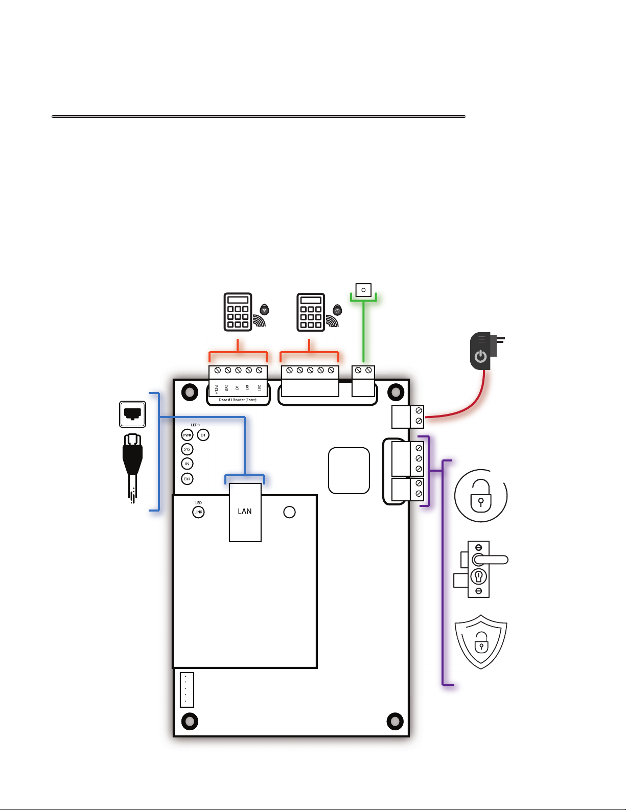
01- Introduction
The world of Access Control can be a challenging yet rewarding solution for the Entry
and Exit of any application. This guide will help you understand the Access Control board
so you can properly connect Readers, MagLocks, Push to Exit buttons, ETC. These boards
have many capabilities and functions they can produce. They oer services, such as, normal
shift and multi-shift time attendance management system; xed ration dining management
system; meeting attendance management system; Online patrol management system and
security alarm management system (features vary by boards). When dealing with Access
Control the possibilities are nearly endless.
Push
Access
Access
to Exit
LED
ACT
+12vDC
Door #1
D1
GRD
Door #1 Reader (Exit)
Push To Exit
D0
LED
Door #1
Relay
P1
GRD
Board PWR
+12vDC
GRD
COM
NO
NC
Door #1 Lock
S1
GRD
Door #1
D1
D0
GRD
+12vDC
Door #1 Reader (Enter)
LED’s
PWR
D1
SYS
IN
ERR
LED
LINK
LED
LAN
1
2
3
4
5
Fire Control Interface
Page# 3
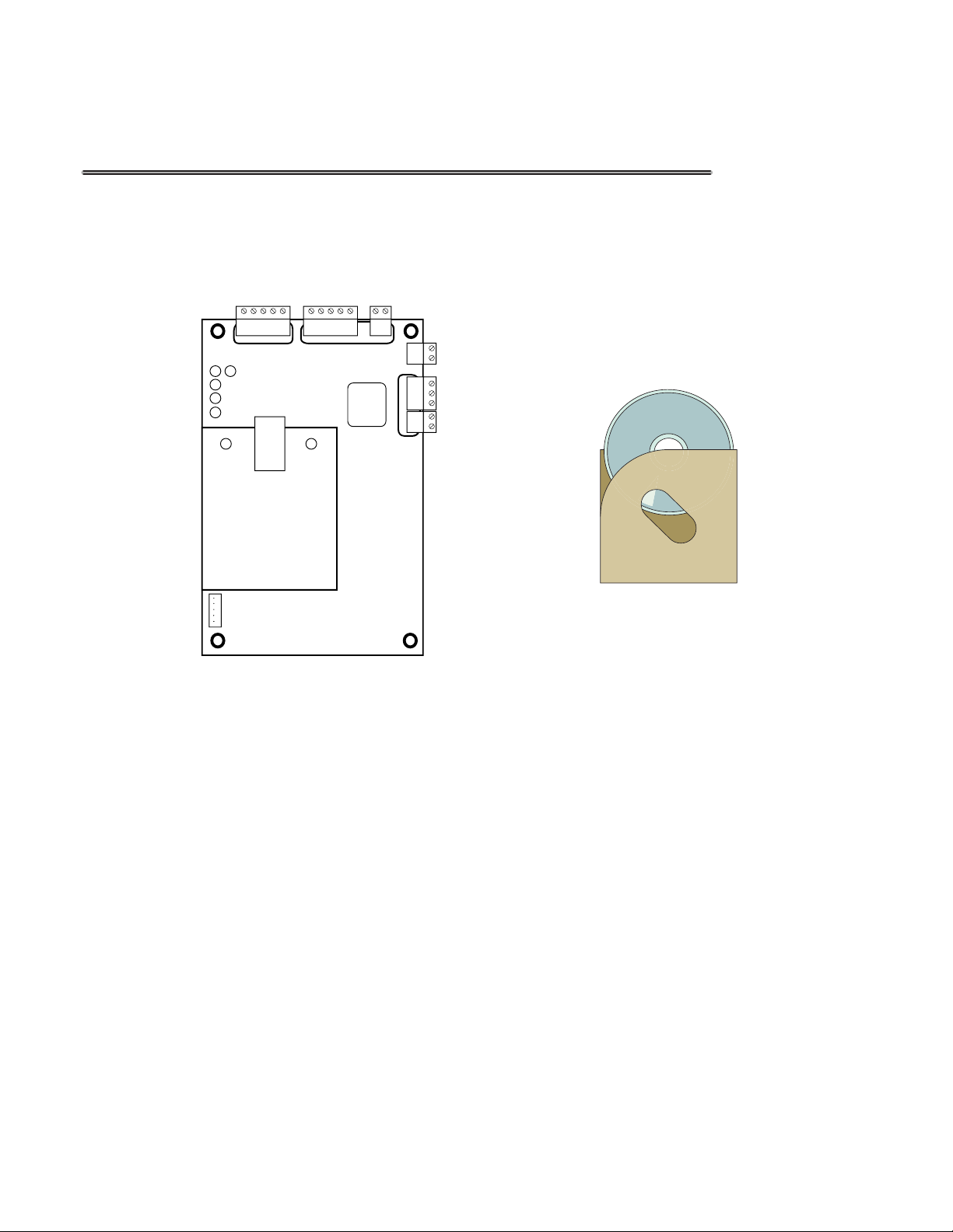
02 - Overview
02.1 - Package Contents
Access Control Software
Access Control Board Access Control Software
02.2 Installation Requirements
• Power Distribution Panel
• Access Control Readers
• Access Control Locks
• Push to Exit buttons
• Cat 5/6 Cable
• Security Wire (22/4 {Shielded} or better)
• Windows XP or Newer PC
Page# 4
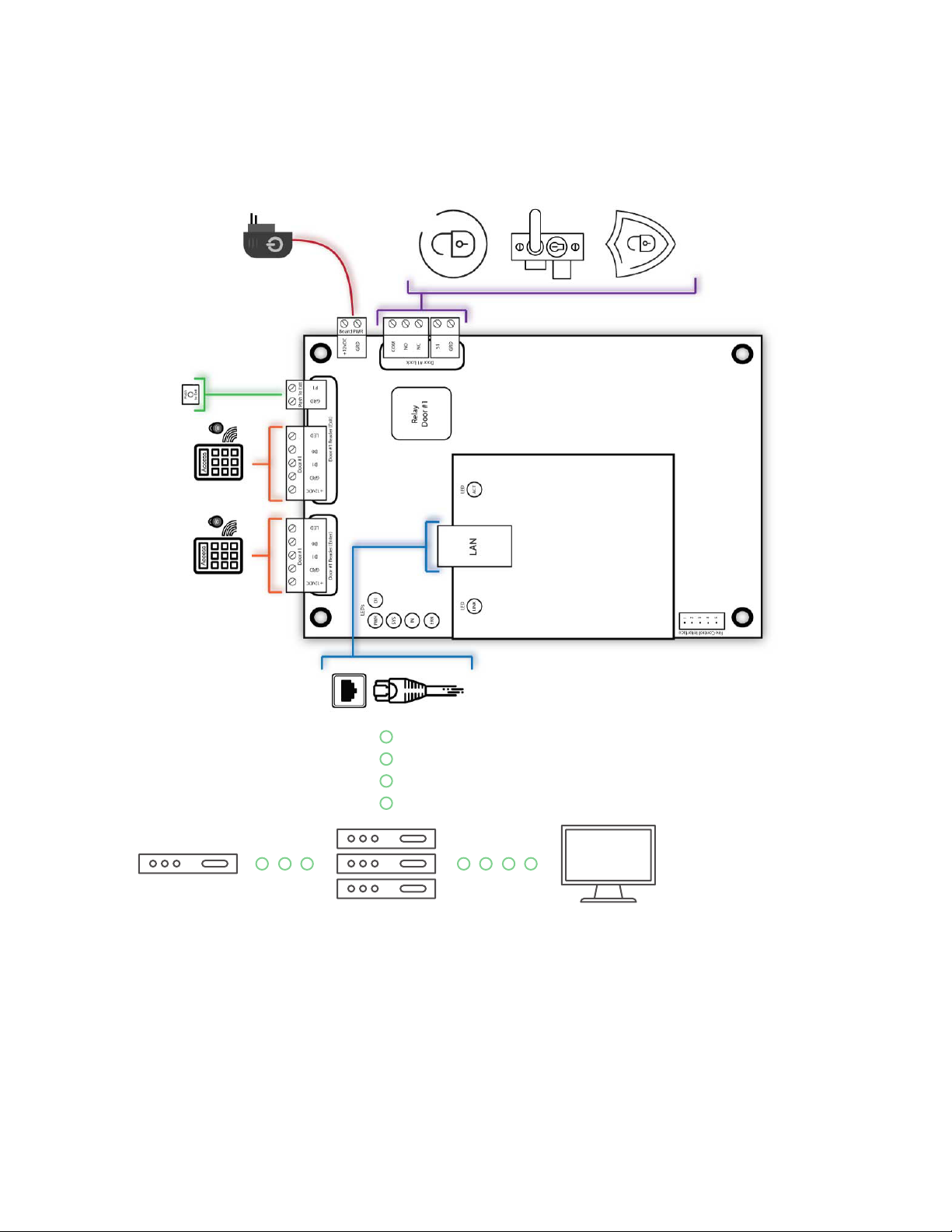
02.3 - Network Overview
Access Control Board
Switch or Hub PC W/ AC SoftwareRouter
Page# 5
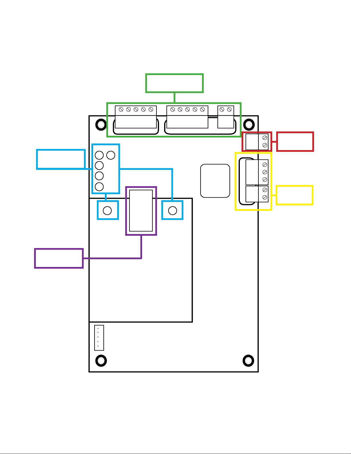
02.4 - Board Overview
Door Connections
Section 05.1-05.7
LED’s Section
03.1-03.2
LAN Section
07.1
PWR
SYS
ERR
LED
ACT
+12vDC
Door #1
D1
GRD
Door #1 Reader (Exit)
Push To Exit
D0
LED
Relay
Door #1
P1
GRD
Board PWR
Door #1 Lock
+12vDC
GRD
COM
NO
NC
S1
GRD
Power
04.1-04.2
Locks
06.1-06.8
Door #1
D1
D0
GRD
+12vDC
Door #1 Reader (Enter)
LED’s
D1
IN
LED
LINK
LED
LAN
Fire Control Interface
1
2
3
4
5
Page# 6
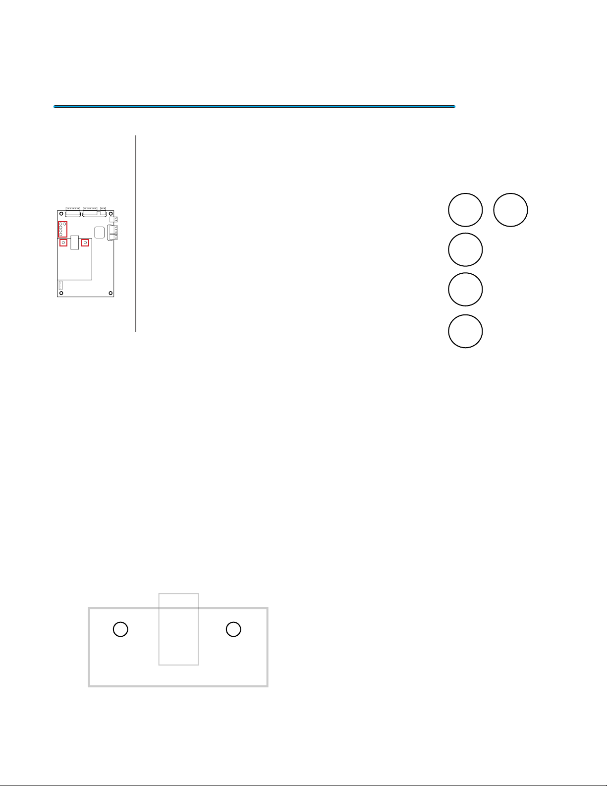
03 - LED’s
03.1 Main Board LED’s
Location On Board
The Access Control board possess a collection
of LED indicator lights to give you visual information of
the activity or errors that occur on the board. This can be
useful if you are having problems with communication or
to verify if it is operating correctly. The gure to the left is
a layout of the main board LED’s. Each one has its own
purpose and with the details laid out below.
• PWR LED: This LED shows the status of the Access
Control Board. This LED will show a Solid Red light
when the board receives power.
• SYS LED: This LED represents the status of the
board. When everything is functioning correctly it will
show a Blinking Green light.
• IN LED: This LED will have a Blinking Yellow light when an Enter reader
request entry to a door.
• ERR LED: This LED illuminates no light if everything is functioning correctly.
When the board receives an Error it will project a Solid Red light.
PWR
SYS
IN
ERR
LED’s
D1
03.2 - LAN LED’s
LED
LINK
LED
ACT
The last 2 LED’s are located on the LAN
card. Below will give you a better explanation of
the purpose.
• LINK LED: This LED will have a Solid Green light
when you have established connection through
the LAN port.
• ACT LED: This LED will blink with a Amber light
when there is network activity.
Page# 7
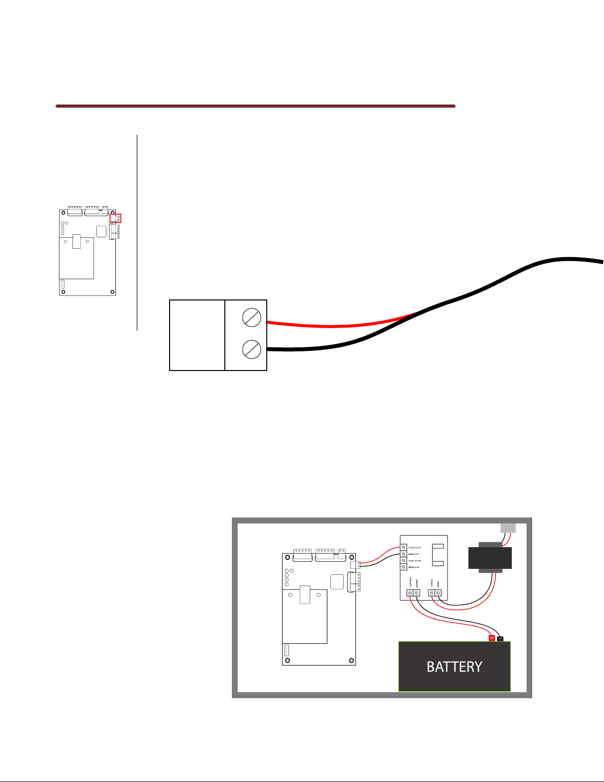
04 - Power
04.1 Powering the Board
This next section is for powering your Access Control board. This
Location On Board
board has minimal power requirements of only 100mA (12vDC) but it will
require extra power when connecting Readers and Push-to-Exit buttons. It is
recomended to use a NEMA box that can house the board and Power Supply.
We recommended using a 3 amp Power Supply to provide enough power for
all the additional equipment (excluding locks). Below is an explanation of how
to connect power to the board.
Board PWR
+12vDC
GRD
• +12vDC: This port is the 12vDC input from the
Power Supply. It is typically a Red Wire.
04.2 - Power Boxes
Choosing the right
power supply can be
tricky because you also
need a Box that can
power and house your
Access Control Board.
You also want to make
sure it includes other
features like Battery
Backup and Fire
Control.
• GRD: This port is the Ground input from the
power supply. It is typically a Black Wire.
Board PWR
+12vDC
GRD
1
2
3
4
5
Page# 8

05 - Door Connections
05.1 Connecting a Reader
Access Control Readers are what allows you to gain access to an entry
Location On Board
door. Connecting them is easy as long as you know what you are doing. Most
of the labels on the board for each port correspond to the reader but below will
explain in more detail how it works.
+12vDC
Tips
The colors used in
this example are only
for example. Please
refer to the reader’s
user manual for an
accurate color chart
to avoid any Connec-
tion issues.
01
GRD
D1
D0
LED
• +12vDC: This port is the 12vDC output to provide power to the reader. It is
typically a Red Wire.
• GRD: This port provides Ground to the reader. It is typically a Black Wire.
• D1: This is a Data port to transmit data from the reader and send it to the
board. It is typically a Gray or White Wire.
• D0: This is a Data port to transmit data from the board and send it to the
Reader. It is typically a Green Wire.
• LED: This is the port where you connect the LED cable from the reader to. It
is only required if the reader needs it. It is typically a Blue Wire. (Optional) you
can also connect your BEEP wire to this port for added features.
Door #1
ID C
ard
00099856485 151,23356
Access Control Readers come in
dierent forms but function all the
same. They use input from either a
Card, Fob, Finger Print, or Numerical
text input as a form of identication.
Page# 9

05.2 - Connect a Push-to-Exit
Push-to-Exit buttons are usually put on the interior part of the door and
allows you to exit once pressed. Connecting them is a breeze and below will
provide the guide.
Push To Exit
GRD
P1
• GRD: This port provides Ground to the Push-to-Exit Button. The wire that is
connected to this port is typically called the Common Wire.
• P1: This port is the signal port to tell the board to open the corresponding
door. When connecting a simple button there is only one combination
involved which is NO (Normally Open). This means that the door in normally
locked until the button is pressed. With more advanced buttons you have 2
options NO and NC (Normally Closed). The NO operates as explained above
but NC will keep the door open until the button is pressed. The default is
NO. The 1 in P1 is the door number the Push-to-Exit Button corresponds to.
For example, P2 is for Door 2.
05.3 - Connecting Multiple Readers
+12vDC
Door #1 Reader (Enter)
GRD
Door #1
D1
D0
LED
+12vDC
GRD
Door #1
D1
Door #1 Reader (Exit)
D0
LED
Push To Exit
GRD
P2
control boards is the option to connect multiple
readers per door. This is used for attendance and
anti-passback. As shown in the gure to the left,
you could connect 2 readers to the board (one
connected to the enter side and the other to the
exit.) You would then proceed to place the Enter
reader on the exterior part of the door and the
exit reader to the interior. This means that instead
of using a Push-to-Exit button to leave you will
have to use the reader instead. Please make
sure you connect the Enter reader to the “Enter”
reader ports and the same with the Exit reader.
You can see an example of this in Section 05.6
labeled “Dual Readers”.
Exclusive to the 1 and 2 door access
Page# 10

05.4 - Attendance
Keeping track of employees attendance can be time consuming and
hard to keep accurate. This access control board can do all this for you. It can
track time arrived, lunch breaks, and time of departure.
In the illustration to the
left you can see how
someone would use
their ID Card to enter the
building and the Access
Control board records
their time. On the right
you can see that same
person leaving the
d
ar
6
5
C
3
3
2
,
1
D
5
I
1
5
8
4
6
5
8
9
9
0
0
0
building and the board
recording the time of
their departure. When
set up you can also
track when a person
leaves and arrives for
lunch.
ID C
0
a
r
d
0
0
9
9
8
5
6
4
8
5
1
5
1
,
2
3
3
5
6
+12vDC
Door #1
D1
GRD
Door #1 Reader (Exit)
Push To Exit
D0
LED
P1
GRD
Door #1
D1
GRD
+12vDC
Door #1 Reader (Enter)
D0
LED
05.5 - Anti-Passback
To be used in conjunction with attendance or, on its own, AntiPassback can be a very useful tool for people entering or exiting a building. It’s
purpose is to make sure a person checks in and checks out. For example, if
a person enters a building with their ID Card and does use their ID Card when
they leave they will not be able to re-enter. In order for the person to re-enter
they will either have to talk to someone to reset their card or clock out from the
exit reader. This feature requires 2 readers per door just like attendance.
Door #1
D1
GRD
+12vDC
Door #1 Reader (Enter)
Door #1
D1
D0
LED
+12vDC
GRD
Door #1 Reader (Exit)
D0
Push To Exit
LED
P1
GRD
Page# 11
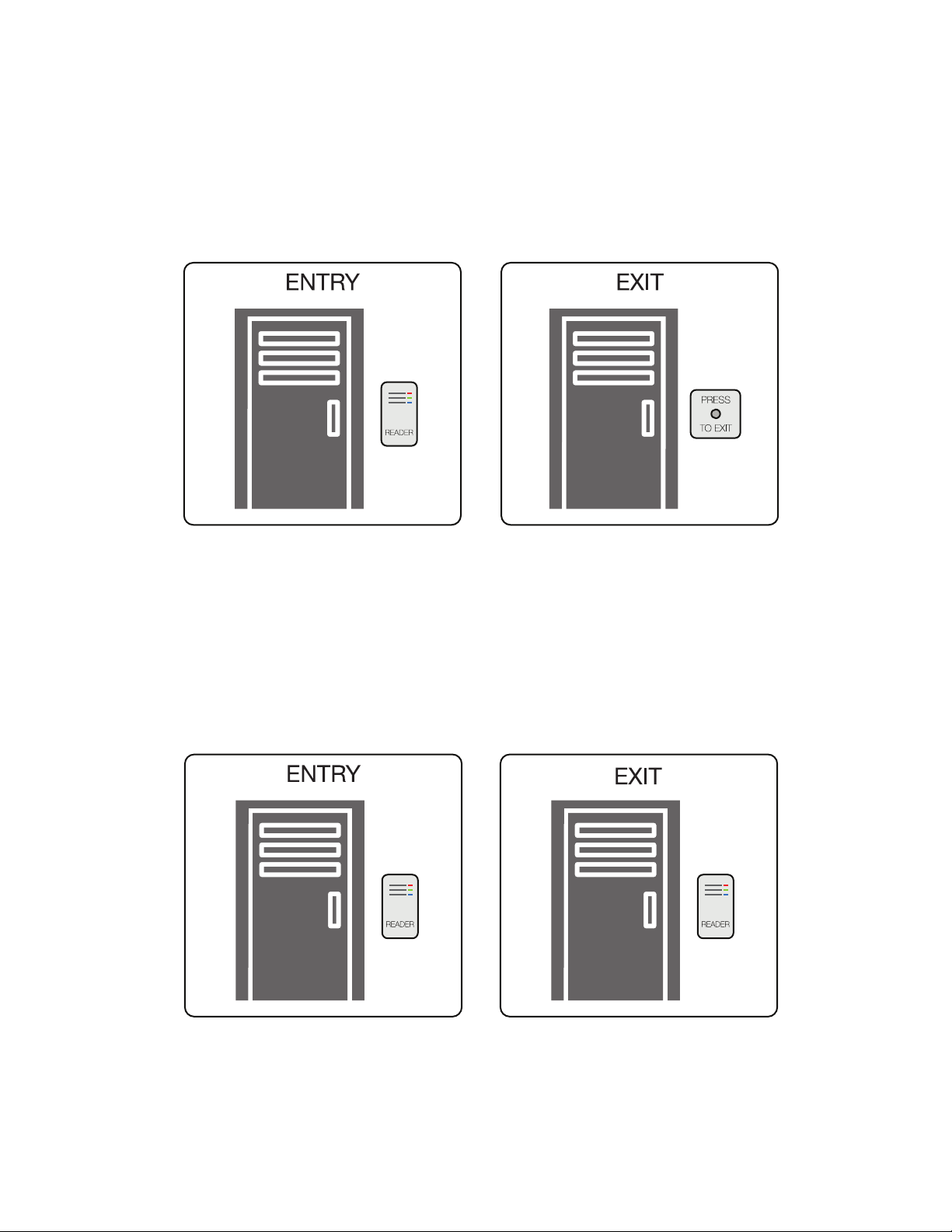
05.6 - Door Example’s
Standard
Above illustrates how you would connect a standard entry and exit for a
single door. The reader would be on the exterior of the door and the Push-toExit button would be placed on the interior.
Dual Readers
Above illustrates how you would connect a dual reader for a single door. On
this board you have the option to connect not only an Enter reader but also an
Exit Reader. This will allow you to perform the attendance and anti-passback
features.
Page# 12
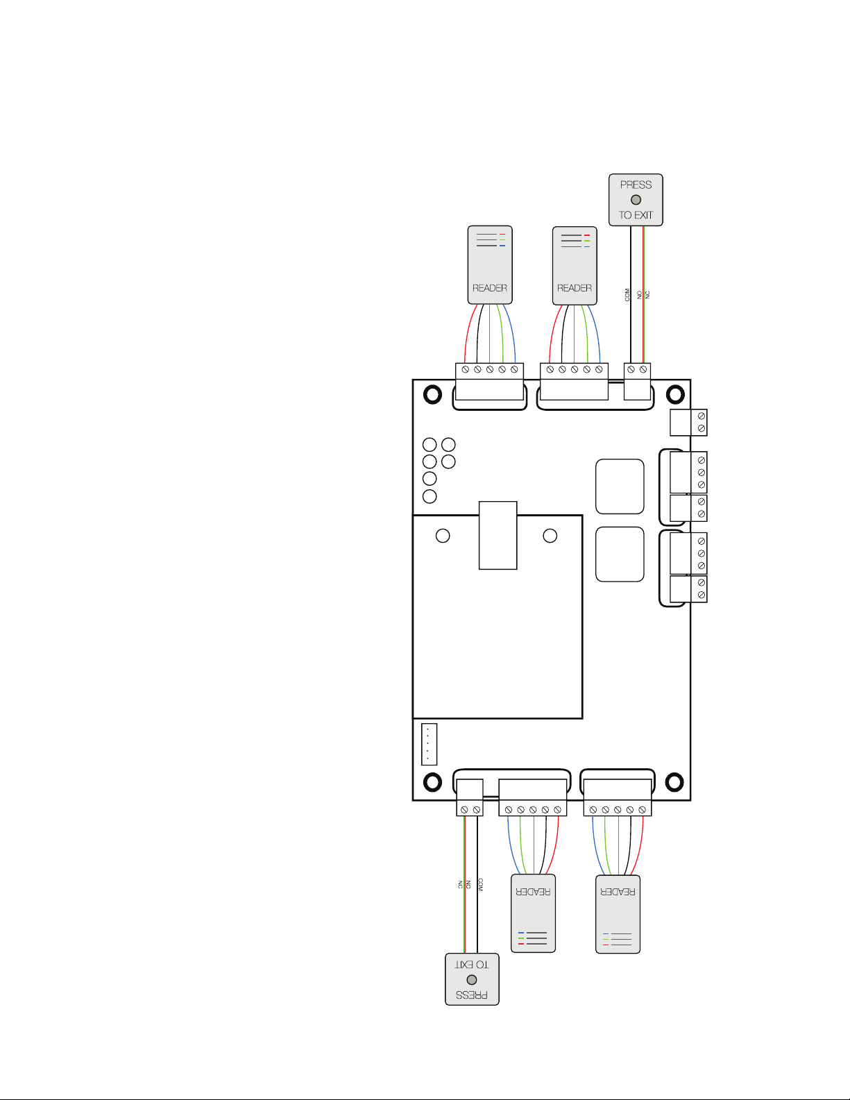
05.7 - Board Example
This example illustrates
how you would connect a Reader
and a Push-to-Exit button, or 2
readers for each door. Because
this is a 1 door board you can
connect 1 reader and 1 Push-toExit button or 2 readers (2 per
Door). For Standard Installations,
the reader functions as a form
of entry and is usually placed on
the exterior. You would then use
a form of identication such as
a ID Card, Fob, Fingerprint, or
Numerical text input. If valid it
will allow you to enter. The Pushto-Exit will provide a convenient
way to exit a locked door. As
explained in the previous page
you can connect an interior
reader to exit and remove the
Push-to-Exit function.
LED
ACT
+12vDC
Door #1
D1
GRD
Door #1 Reader (Exit)
Push To Exit
D0
LED
Relay
Door #1
Relay
Door #2
P1
GRD
Board PWR
+12vDC
GRD
COM
NO
NC
Door #1 Lock
S1
GRD
COM
NO
NC
Door #2 Lock
S2
GRD
Door #1
D1
D0
LED
GRD
+12vDC
Door #1 Reader (Enter)
LED’s
PWR
D1
D2
SYS
IN
ERR
LED
LINK
LAN
Also if you want to use
multiple Push-to-Exit buttons you
can simply input another button.
Please be sure to continue the
same function (NO or NC) as you
can only use one at a time.
1
2
3
4
5
Fire Control Interface
GRD
P2
Push To Exit
LED
Door #2 Reader (Exit)
D1
D0
+12vDC
GRD
Door #2
LED
Door #2 Reader (Enter)
+12vDC
GRD
D1
D0
Door #2
Page# 13

06 - Locks
06.1 Connecting a Lock
The type of lock that you use will depend on the application and door.
Location On Board
NoTice
Please make sure
when connecting a
single lock to only
use one of the 2
choices (NO or NC).
You have a few options to choose from and you can use multiple locks at a
time. Some examples include Strikes, Maglocks, and Deadbolts. Below will
explain how to connect these locks to the board.
COM
NO
NC
S1
GRD
01
• NO: This port stands for Normally Open. This means there is no electrici-
ty owing through this port in its normal state. The type of lock you would
connect to this port would be a Fail Secure lock. This is where you would
connect the + wire from the lock. (Please See Notice 01)
• COM: This port
is your +12vDC
input from your
power supply.
The locks don’t
receive power
from the board
directly and need
to be wired, from
the COM port, to
the power supply
individually. You
can use the same
power supply as
the board or a
separate PWR
Supply depending
on power
consumption of all
the equipment
Tips
To nd out more
information about
Normally Open,
Normally Closed, Fail
Safe, or Fail Secure
please go to sections
06.6 - 06.8
02
• NC: This port stands for Normally Closed. This means there is electricity
owing through this port in its normal state. The type of lock you would connect to this port would be a Fail Safe lock. This is where you would connect
the + wire from the lock. (Please See Notice 01)
• GRD: This port is where you would connect the Ground (-12vDC) wire from
the Lock. You can also run the ground cable to the Power Supply if the port
is getting too congested.
Page# 14

06.2 - Connecting Multiple Locks
The example below shows how you would connect 2 or more locks to
a single door. You would just run separate cables to the locks and depending
on what types of locks you are using you would connect them to either NO
or NC. Please make sure you use ample amount of power for all the locks
connect to the board.
COM
NO
NC
S1
GRD
example
COM
NO
NC
S1
GRD
Page# 15
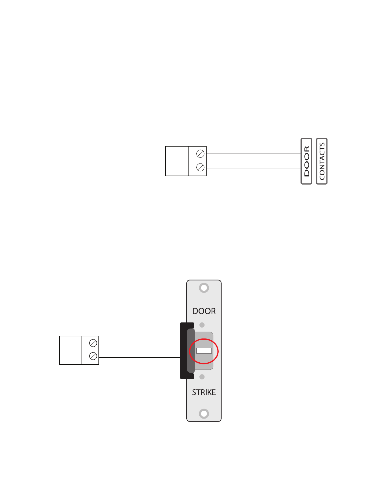
06.3 - Connecting Signal Wire
The Signal port is used to tell the Access Control board if the door
is open or closed. This is important because when you enter or exit a door
the locks will reengage even if the door is still open. If you want to know this
information or have an alarm go o for having the door open for an extended
period of time this port will allow you to do so.
• S1: This port is what
you will connect your
signal wire to. If you
have a choice between
NO and NC, you will
want to choose NC
because the door is
normally closed and
you want to know when
it is open. The example
to the right shows a
simple door contact
you would use on an
alarm system to help
indicate if the door is
open. You will need to
run one for each door
and put them in the
correct “S” port.
• GRD: This port is where you would connect the COM or
S1
GRD
negative side of the contact. With the example above it
does not matter what cable you use because you are just
trying to complete the circuit. You can also connect to the
GRD cable powering the strike as this is the same ground.
This will cut down on the amount of cable needed.
S1
GRD
NC
The example to the left is
using a Strike that has the
door signal built in. This
is seen in more expensive
models and is located
typically in the middle of
the strike plate. There are
usually 3 wires with the rst
being COM. This cable you
will connect to the GRD
port. The other 2 cables will
be NO & NC. As explained
above you will use NC.
Page# 16

06.4 - Powering Locks with Same PWR Supply
This example will illustrate how to power your locks with the same
power source as your board. As you might have noticed your locks do not get
powered from the Access Control board and need to be powered separately. If
your Power Supply for your board is powerful enough for your board, readers,
and locks you can use the same supply. You would simply connect the 12vDC
output from your power supply to each COM port for each lock.
Door #1
Door #1
D1
D0
LED
GRD
+12vDC
Door #1 Reader (Enter)
LED’s
PWR
D1
SYS
IN
ERR
LED
LINK
LAN
1
2
3
4
5
Fire Control Interface
Push To Exit
D1
D0
P1
LED
GRD
GRD
+12vDC
Door #1 Reader (Exit)
LED
ACT
Door #1
Board PWR
+12vDC
GRD
COM
NO
Relay
NC
Door #1 Lock
S1
GRD
If you have a power supply with multiple channels you can connect to
dierent channels on the supply. This will help distribute power. You don’t have
to worry about the GRD because that is something the board does share with
the locks.
Door #1
Door #1
D1
D0
LED
GRD
+12vDC
Door #1 Reader (Enter)
LED’s
PWR
D1
SYS
IN
ERR
LED
LINK
LAN
1
2
3
4
5
Fire Control Interface
Push To Exit
D1
D0
P1
LED
GRD
GRD
+12vDC
Door #1 Reader (Exit)
LED
ACT
Board PWR
+12vDC
GRD
COM
NO
Relay
NC
Door #1
Door #1 Lock
S1
GRD
Page# 17
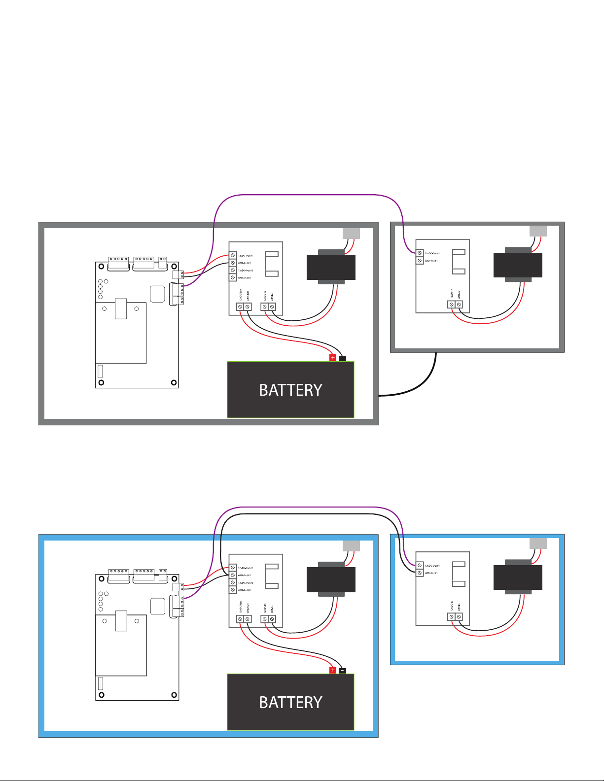
06.5 - Powering Locks with Seperate PWR
This example will illustrate how to power your locks with a separate Power Supply.
Since your locks share the same ground as your Access Control board you have to Bond the
two Power Supplies together. You would simply connect the 12vDC output from your separate
power supply to each COM port for each lock. Below is an example 2 Metal Power Supply
Boxes. The chassis themselves are grounded so connect a 14 gauge wire to both chassis to
bond them together. This will allow them to share the same Ground to complete the circuit.
Door #1
Door #1
D1
D0
LED
GRD
+12vDC
Door #1 Reader (Enter)
LED’s
PWR
D1
SYS
IN
ERR
LED
LINK
LAN
1
2
3
4
5
Fire Control Interface
Push To Exit
D1
D0
P1
LED
GRD
GRD
+12vDC
Door #1 Reader (Exit)
LED
ACT
Board PWR
+12vDC
GRD
COM
NO
Relay
NC
Door #1
Door #1 Lock
S1
GRD
GROUND THE CHASSIS
TO EACH OTHER
For ABS housings, you cannot bond the two Chassis together so instead you will have to connect them dierently.
You will have to run a 14 gauge wire from the Ground output on the separate Power Supply to one of the ground
ports in the Main Power Supply. As for the 12vDC you will copy the same set up as before.
Door #1
Door #1
D1
D0
LED
GRD
+12vDC
Door #1 Reader (Enter)
LED’s
PWR
D1
SYS
IN
ERR
LED
LINK
LAN
1
2
3
4
5
Fire Control Interface
Push To Exit
D1
D0
P1
LED
GRD
GRD
+12vDC
Door #1 Reader (Exit)
LED
ACT
Board PWR
+12vDC
GRD
COM
NO
Relay
NC
Door #1
Door #1 Lock
S1
GRD
ABS CHASSIS
Page# 18

06.6 Normally Open and Normally Closed
What is open and closed? Before we get too far we need to explain what is “open”
and “closed”. With electricity “closed” means the circuit is connected and electricity
is owing. “Open” means the opposite. The electrical current is open and no
electricity is owing.
Normally? The idea that something is “normal” means that it is a constant unless
a force changes it. Relays will need to be energized and switches such as Door
contacts need to be disconnected.
Normally Closed - This is when there
is a constant current of electricity
in its normal state. Energizing or
changing the state will open the
contact and disrupt the current.
Normally Open - This is when there is
no current of electricity in its normal
state. Energizing or changing the
state will close the contact and allow
the current to ow.
Do not over think the concept. It is as easy as it sounds. Now lets see how this is
interpreted on the Access Control Board.
Below is a description of a Normally Closed device connected to the Access Control board. When
power is given through the relay and the relay is not energized it stays in a Normally Closed state. The
Normally Open port stays with no current. When the Access control board energizes the relay (From
a Reader asking to open the door) the relay switches the current to Normally Open and the Normally
Closed port looses current. So it is safe to say that the Access control boards are Normally Closed
devices by default.
COM
NO
NC
S1
GRD
COM
NO
NC
S1
GRD
Page# 19

06.7 Fail Safe Vs. Fail Secure
This section is very easy to understand but should not be overlooked.
When incorporating these protocols in your installation you should
always talk to your local code enforcement to ensure it is correct.
Fail Safe? These products are designed to unlock when power is lost. This ensures
that if there is a problem you can quickly exit. Since this is Normally Open device you
will want to provide power in order for it to be locked.
Fail Secure? These products are designed to stay locked when power is lost. This
ensures your door will stay locked even in the event of a power loss. This might
seem like the best option but you have to remember that if it stay locked everyone
inside is also locked in. Please make sure to have an internal mechanical exit
function to overcome this. Since this is Normally Closed device you will only provide
power when needed to unlock.
06.8 - Types of Locks
Magnetick Lock - These locks work o magnetic
energy to clamp the door shut. They are very
strong ranging from 350lbs to upwards of 1200lbs
of holding force and can easily be released.
MagLocks are Fail Safe devices which makes them
Normally Open. This means you want to connect
the Maglock to the NC port to provide power and
keep the door locked until requested open. You can
place these devices in the frame or door itself.
Dead Bolt - These locks work same way a
mechanical DeadBolt by inserting a metal bolt
into the door to prevent opening. They have a
tremendous holding force upwards of 2200lbs.
DeadBolts are Fail Safe devices which makes them
Normally Open. This means you want to connect
the DeadBolt to the NC port to provide power and
keep the door locked until requested open. You can
place these devices in the frame or door itself.
Door Strike - These locks are located in the door
frame and hold a door back when the strike is
inserted. They also come in two forms, one being
Fail Safe (NO) and the other Fail Secure (NC). Fail
safe works like explained with the DeadBolt and
MagLock. Fail Secure is a Normally Closed device
and keeps the door locked until power is received.
This means you connect the Fail Secure device to
the NO port.
Page# 20

07 - Lan
08.1 Connecting to the Network
Connecting to the network is very easy and only requires one Ethernet Cable.
Location On Board
You will simply connect the Ethernet cable to the Lan Card located on the
board. then you connect the other end of the Ethernet cable to a HUB on your
network the your Computer with the Access Control Software is located. For
an even more secure connection you can plug directly into the computer. This
will ensure no one can intercept connectivity through the network.
IP Address
LED
LINK
LED
ACT
LAN
192.168.0.0
Subnet
255.255.255.0
Gateway
0.0.0.0
All of this information can be changed on the Access Control Software you
install on the PC. You will be able to connect to the board regardless of your
network conguration. The software has a nder tool built in so you can
access a new board easily.
Page# 21

08 - Extras
08.1 Connecting a Siren, Buzzer, or Light
Access Control can allow you to do some impressive things to help indicate
Location On Board
the door is open or closed. Below will explain how to connect these devices.
• COM: This port is your
12vDC input from your
power supply. Since
this is the same section
as where your locks
would go you can refer
to Section 06 for further
information.
COM
NO
NC
S1
GRD
You can use these devices for multiple applications. For example, you can use a light above
the door to indicate that it is unlocked, informing someone trying to enter or exit that they can
do so. This is a good solution for low light situations. Another example, which can be used
in conjunction with a Push-To-Enter button, when the button is pressed a buzzer alerts the
person that the door is now unlocked and can be opened. These ideas and more can be used
separately or together to create customizable experiences for you and your client.
• NO: This is the port
where you will connect
the +12VDC for the
alarm you choose.
Connecting to this port
will start your alarm
and provide indication
of when the door is
unlocked.
• GRD: This port is where
you would connect the
Ground wire from the
alarm. You can also
run the ground cable
to the Power Supply if
the port is getting too
congested.
Just remember, if you connect these devices, when you leave the door unlocked the buzzer
will continue to go o. A simple relay connected to the Push-to-Enter button will work better
for that installation. Please call our tech support for further instruction.
Page# 22

08.2 Connecting a Push-to-Enter Button
Location On Board
Push-to-Enter buttons are the same as Push-to-Exit but placed near a
receptionist to let someone in. They are also connected the same way. Follow
the steps for the Push-to-Exit button found in Section 05.2 but only connect
the NO cable to the (P1 [1-4]) port. You can connect as many Push-to-Enter or
Push-to-Exit buttons as you like but make sure they are all running the same
cable (NO or NC).
Push To Exit
GRD
P1
08.3 Connecting a Request-to-Exit “PIR”
Location On Board
PIR Request-to-Exit devices allow you to use motion to open the door. This
means when you approach the door the sensor will detect your movements
and open the door. A good example is when you walk into a convenience
store, the PIR will detect you are getting close to the door and the automated
doors will open. These are connected to the same ports as the Request-to Exit
& Request-to-Enter buttons.
Push To Exit
GRD
P1
Page# 23

PLEASE MAKE SURE YOU HAVE A TRAINED
ELECTRICIAN INSTALL THIS EQUIPMENT.
Page# 24
 Loading...