

TechVision D Series, AB-D1EWN Quick Start Manual
QUICK START GUIDE FOR ACCESS
CONTROL BOARDS
D Series One Door TCP/IP Web Server Controller
Model: AB-D1EWN

Table of Contents
3 01- Introduction
4 02 - Overview
4 02.1 - Package Contents
4 02.2 - Installation Requirements
5 02.3 - Network Overview
6 02.4 - Board Overview
7 03 - LED’s
7 03.1 - Main Board LED’s
7 03.2 - LAN LED’s
8 04 - Power
8 04.1 - Powering the Board
8 04.2 - Power Boxes
9 05 - Door Connections
9 05.1 - Connecting a Reader
10 05.2 - Connect a Push-to-Exit
10 05.3 - Connecting Multiple Readers
11 05.4 - Attendance
11 05.5 - Anti-Passback
12 05.6 - Door Example
13 05.7 - Board Example
14 06 - Locks
14 06.1 - Connecting a Lock
15 06.2 - Connecting Multiple Locks
16 06.3 - Connecting Signal Wire
17 06.4 - Powering Locks with Same PWR Sup
18 06.5 - Powering Locks with Seperate PWR
19 06.6 - Nornally Open and Normally Closed
20 06.7 - Fail Safe Vs. Fail Secure
20 06.8 - Types of Locks
21 07 - Lan
21 08.1 - Connecting to the Network
22 08 - Extras
22 08.1 - Connecting a Siren, Buzzer, or Light
23 08.2 - Connecting a Push-to-Enter Button
23 08.3 - Connecting a Request-to-Exit “PIR”
Page# 2
01- Introduction
The world of Access Control can be a challenging yet rewarding solution for the Entry
and Exit of any application. This guide will help you understand the Access Control board
so you can properly connect Readers, MagLocks, Push to Exit buttons, ETC. These boards
have many capabilities and functions they can produce. They oer services, such as, normal
shift and multi-shift time attendance management system; xed ration dining management
system; meeting attendance management system; Online patrol management system and
security alarm management system (features vary by boards). When dealing with Access
Control the possibilities are nearly endless.
Push
Access
Access
to Exit
LED
ACT
+12vDC
Door #1
D1
GRD
Door #1 Reader (Exit)
Push To Exit
D0
LED
Door #1
Relay
P1
GRD
Board PWR
+12vDC
GRD
COM
NO
NC
Door #1 Lock
S1
GRD
Door #1
D1
D0
GRD
+12vDC
Door #1 Reader (Enter)
LED’s
PWR
D1
SYS
IN
ERR
LED
LINK
LED
LAN
1
2
3
4
5
Fire Control Interface
Page# 3
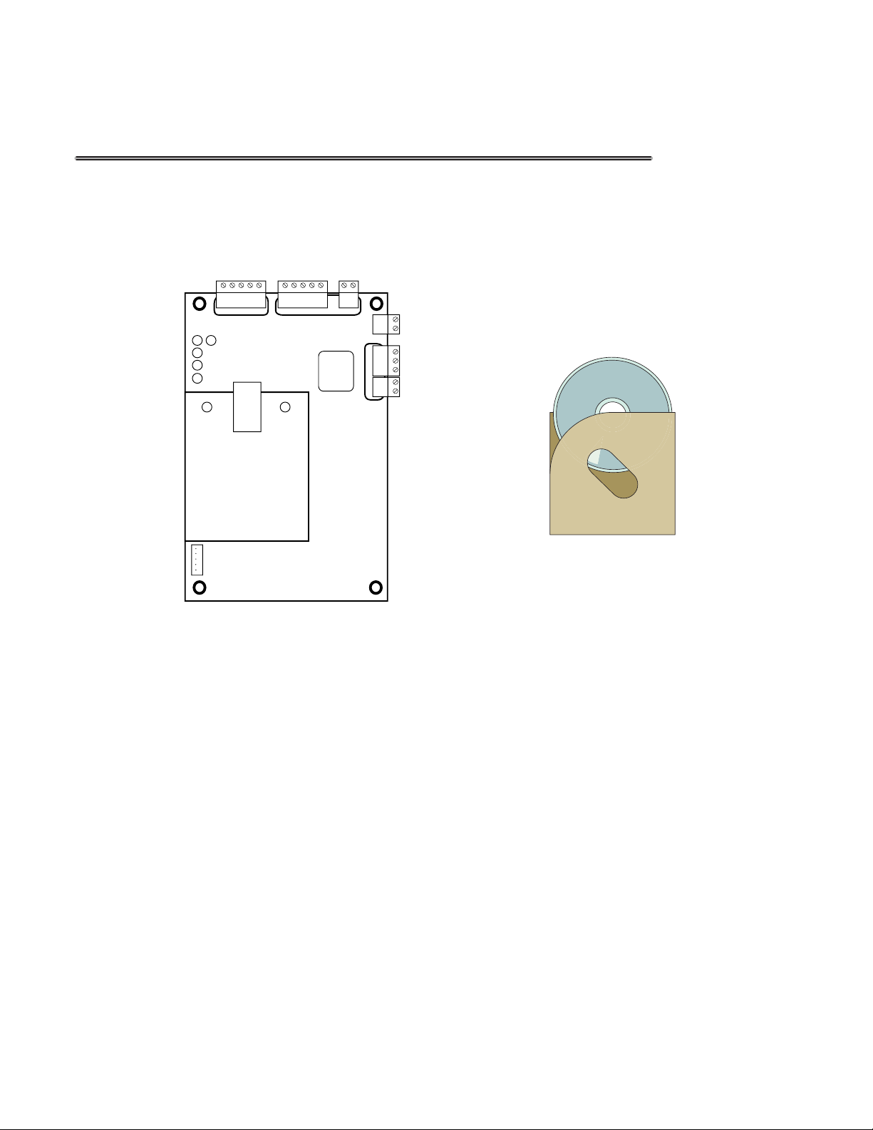
02 - Overview
02.1 - Package Contents
Access Control Software
Access Control Board Access Control Software
02.2 Installation Requirements
• Power Distribution Panel
• Access Control Readers
• Access Control Locks
• Push to Exit buttons
• Cat 5/6 Cable
• Security Wire (22/4 {Shielded} or better)
• Windows XP or Newer PC
Page# 4
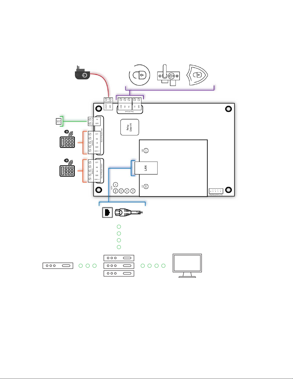
02.3 - Network Overview
Access Control Board
Switch or Hub PC W/ AC SoftwareRouter
Page# 5
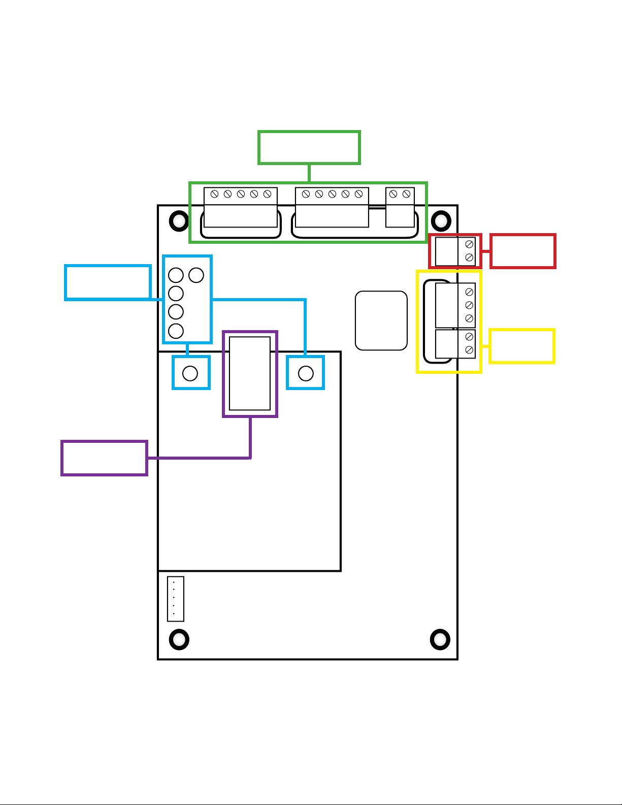
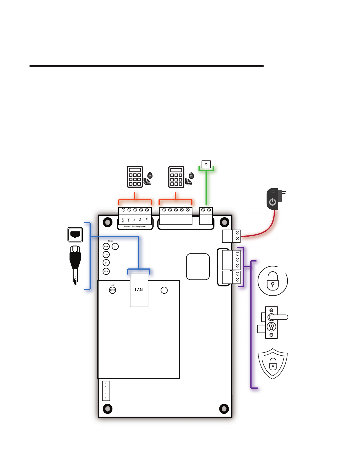
02.4 - Board Overview
Door Connections
Section 05.1-05.7
LED’s Section
03.1-03.2
LAN Section
07.1
PWR
SYS
ERR
LED
ACT
+12vDC
Door #1
D1
GRD
Door #1 Reader (Exit)
Push To Exit
D0
LED
Relay
Door #1
P1
GRD
Board PWR
Door #1 Lock
+12vDC
GRD
COM
NO
NC
S1
GRD
Power
04.1-04.2
Locks
06.1-06.8
Door #1
D1
D0
GRD
+12vDC
Door #1 Reader (Enter)
LED’s
D1
IN
LED
LINK
LED
LAN
Fire Control Interface
1
2
3
4
5
Page# 6
03 - LED’s
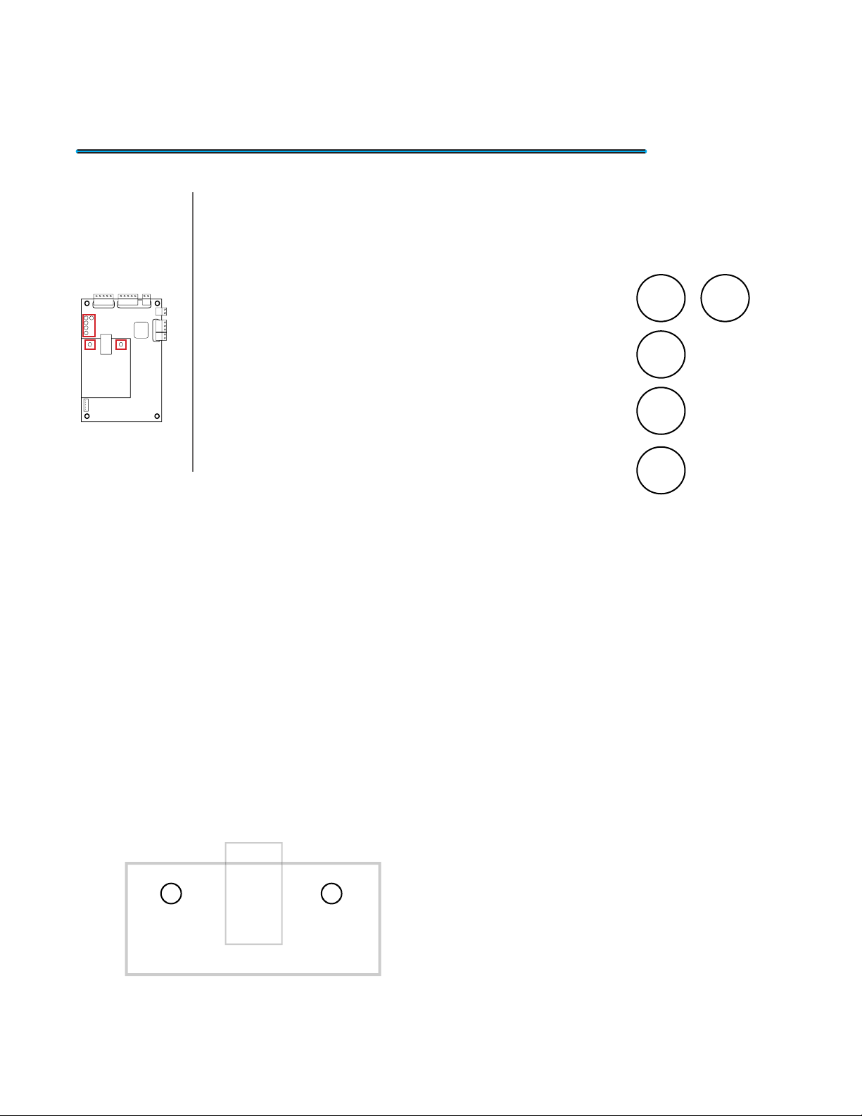
03.1 Main Board LED’s
Location On Board
The Access Control board possess a collection
of LED indicator lights to give you visual information of
the activity or errors that occur on the board. This can be
useful if you are having problems with communication or
to verify if it is operating correctly. The gure to the left is
a layout of the main board LED’s. Each one has its own
purpose and with the details laid out below.
• PWR LED: This LED shows the status of the Access
Control Board. This LED will show a Solid Red light
when the board receives power.
• SYS LED: This LED represents the status of the
board. When everything is functioning correctly it will
show a Blinking Green light.
• IN LED: This LED will have a Blinking Yellow light when an Enter reader
request entry to a door.
• ERR LED: This LED illuminates no light if everything is functioning correctly.
When the board receives an Error it will project a Solid Red light.
PWR
SYS
IN
ERR
LED’s
D1
03.2 - LAN LED’s
LED
LINK
LED
ACT
The last 2 LED’s are located on the LAN
card. Below will give you a better explanation of
the purpose.
• LINK LED: This LED will have a Solid Green light
when you have established connection through
the LAN port.
• ACT LED: This LED will blink with a Amber light
when there is network activity.
Page# 7
04 - Power
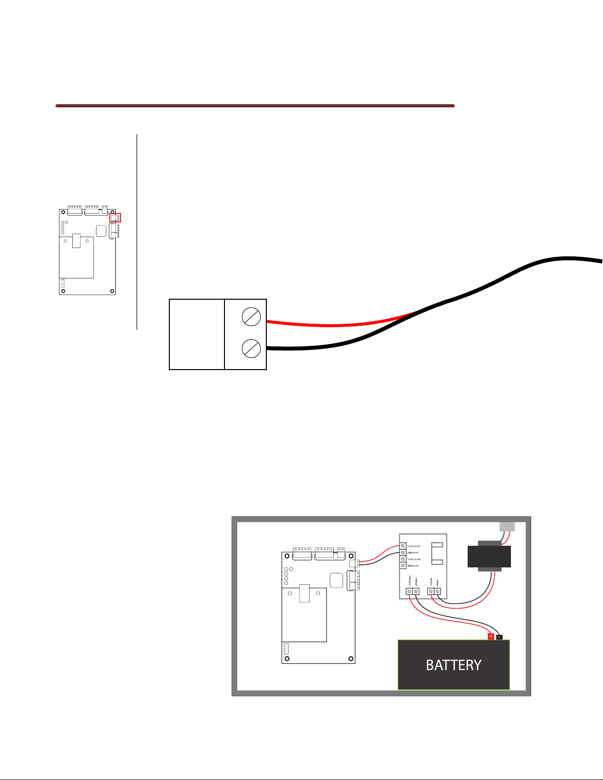
04.1 Powering the Board
This next section is for powering your Access Control board. This
Location On Board
board has minimal power requirements of only 100mA (12vDC) but it will
require extra power when connecting Readers and Push-to-Exit buttons. It is
recomended to use a NEMA box that can house the board and Power Supply.
We recommended using a 3 amp Power Supply to provide enough power for
all the additional equipment (excluding locks). Below is an explanation of how
to connect power to the board.
Board PWR
+12vDC
GRD
• +12vDC: This port is the 12vDC input from the
Power Supply. It is typically a Red Wire.
04.2 - Power Boxes
Choosing the right
power supply can be
tricky because you also
need a Box that can
power and house your
Access Control Board.
You also want to make
sure it includes other
features like Battery
Backup and Fire
Control.
• GRD: This port is the Ground input from the
power supply. It is typically a Black Wire.
Board PWR
+12vDC
GRD
1
2
3
4
5
Page# 8
 Loading...