

Tech Source Raptor 4000e, Raptor 4000-LR, Raptor 4000e-LR, Raptor 4000-R, Raptor 3500e Drivers Installation and Reference Linux Manual
Page 1
Raptor 4000 Series Drivers
Installation and Reference
Publication #65-0271-01 Rev B January 13, 2009
Linux Manual
Copyright © 2009 Tech Source, Inc.
442 Northlake Boulevard
Altamonte Springs, FL 32701
(407) 262-7100
Page 2

Addendum Information
Changes made to:
REVISION
CHANGES DATE
NUMBER
A Initial Release 06-16-08
B Added support for R, LR, & e-LR 01-13-09
The Tech Source logo and Tech Source Raptor are trademarks
of Tech Source, Inc. X Window System is a trademark and
product of X.org.
All other products or services mentioned in this document are
identified by the trademarks or service marks of their respective
companies or organizations. Tech Source, Inc. disclaims any
responsibility for any references to those trademarks herein.
All rights reserved. No part of this work may be reproduced in
any form or by any means without prior written permission of the
copyright owner.
RESTRICTED RIGHTS LEGEND: Use, duplication, or disclosure
by the U.S. Government is subject to restrictions of FAR 52.22714(g)(2)(6/87) and FAR 52.227-19 (6/87); or DFAR 252.2277015(b)(6/95) and DFAR 227.7202-3(a).
The product described in this manual may be protected by one
or more U.S. patents, foreign patents, and/or pending
applications.
Page 3

PREFACE
This publication documents the Tech Source Raptor Drivers for
Linux Installation for use with the Tech Source, Inc. Raptor
graphics cards. This manual is intended for users who
incorporate the Tech Source Raptor graphics cards into x86 PC
workstations/servers.
This is a guide to the installation of the Raptor Drivers for Linux
software. All systems vary to a degree. Knowledge of the
features of your system is helpful during the installation process.
WARRANTY
The Raptor cards are warranted for two (2) years from date of
shipment. During the warranty period, Tech Source, Inc. will, at
its discretion, repair or replace a defective component at its
expense. Freight charges associated with the repair or
replacement of components under warranty are to be shared by
Tech Source, Inc. and the customer. All customers, domestic
and international, shall bear the freight charges for the product
return. Tech Source, Inc. shall bear the outbound freight
charges up to $20.00 (USD) per returned product, whether
domestic or international. Any additional freight charge shall be
the responsibility of the customer. We suggest that you contact
your dealer first with any questions you may have about the
product. Technical support (via telephone/facsimile/email) is
provided for one (1) year from date of shipment. The installation
of any Tech Source, Inc. hardware/software product is the sole
responsibility of the customer.
Tech Source, Inc. offers a continuing hardware/software support
program that provides telephone consultation and any required
hardware repair after the expiration of the warranty period. This
is a billable annual maintenance contract. Contact Tech Source,
Inc. for the available maintenance plans.
Customers will be charged an hourly rate plus materials
($350.00 USD minimum) for repairs and/or maintenance
performed by Tech Source, Inc. that are not covered by a Tech
Source, Inc. warranty or maintenance contract.
Page 4

DOCUMENTATION IS PROVIDED “AS IS” AND ALL
EXPRESSED OR IMPLIED CONDITIONS,
REPRESENTATIONS AND WARRANTIES, INCLUDING ANY
IMPLIED WARRANTY OF MERCHANTABILITY, FITNESS FOR
A PARTICULAR PURPOSE OR NON-INFRINGEMENT, ARE
DISCLAIMED, EXCEPT TO THE EXTENT THAT SUCH
DISCLAIMERS ARE HELD TO BE LEGALLY INVALID.
Page 5

TABLE OF CONTENTS
Introduction ................................................................. 1
1
1.1 Overview.................................................................... 1
Hardware Installation.................................................. 3
2
2.1 Hardware Configurations Supported......................... 3
2.2 Installation Instructions.............................................. 3
Software Installation................................................... 5
3
3.1 Overview.................................................................... 5
3.2 Requirements ............................................................ 5
3.3 CD-ROM Installation ................................................. 6
3.3.1 Step-by-Step Installation Instructions .................... 6
3.3.2 Using the install_all Installation Script ................... 8
3.4 MOX Extension Support............................................ 8
3.5 TSIMISC Extension Support ..................................... 9
3.6 New Device ............................................................. 10
3.7 DDC Resolution....................................................... 11
3.8 Configuration for PC Graphics Hardware................ 11
3.8.1 Monitor Section.................................................... 14
3.8.2 Device Section..................................................... 14
3.8.3 Screen Section..................................................... 16
3.8.4 Server Layout Section ......................................... 17
Invoking the X Server ............................................... 19
4
4.1 Overview.................................................................. 19
4.2 startx........................................................................ 20
4.3 xinit .......................................................................... 20
4.4 xdm.......................................................................... 21
4.5 Configuring the X Server for Multi-Screen Mode .... 22
4.5.1 Configurations for Multiscreen Mode................... 22
4.5.2 Defining Order of Display..................................... 25
4.6 Selecting Bit-Depths on 4000 Series Cards............ 26
4.6.1 Setting Bit-Depth.................................................. 26
4.6.2 MOX Modes......................................................... 29
4.7 Setting Resolution on Raptor 4000 Series Cards ... 29
4.7.1 Setting Resolution................................................ 30
4.7.2 Overriding DDC.................................................... 33
4.7.3 Setting Mode Line................................................ 34
4.8 Rotation Mode Configuration................................... 36
Uninstalling Software ............................................... 39
5
5.1 Uninstalling the Software......................................... 39
Page 6

TABLE OF CONTENTS (Cont'd)
Frequently Asked Questions ................................... 41
6
6.1 Frequently Asked Questions ................................... 41
Technical Assistance ............................................... 43
7
7.1 Who to call for Help ................................................. 43
7.2 Email Address ......................................................... 43
7.3 Website.................................................................... 44
Appendix A Card Specifications .................................... 45
A.1 Raptor 4000 Specifications ..................................... 45
A.2 Raptor 4000e Specifications ................................... 46
A.3 Raptor 4000-LR Specifications................................ 47
A.4 Raptor 4000e-LR Specifications.............................. 48
A.5 Raptor 4000-R Specifications.................................. 49
A.6 Raptor 3500e Specifications ................................... 50
Appendix B DDC Resolutions ........................................ 51
Appendix C
China RoHS Declaration Table.................. 53
©2009 Tech Source Inc. ii Part #65-0271-01
Page 7

Raptor 4000 Series: Reference Manual
1 Introduction
1.1 Overview
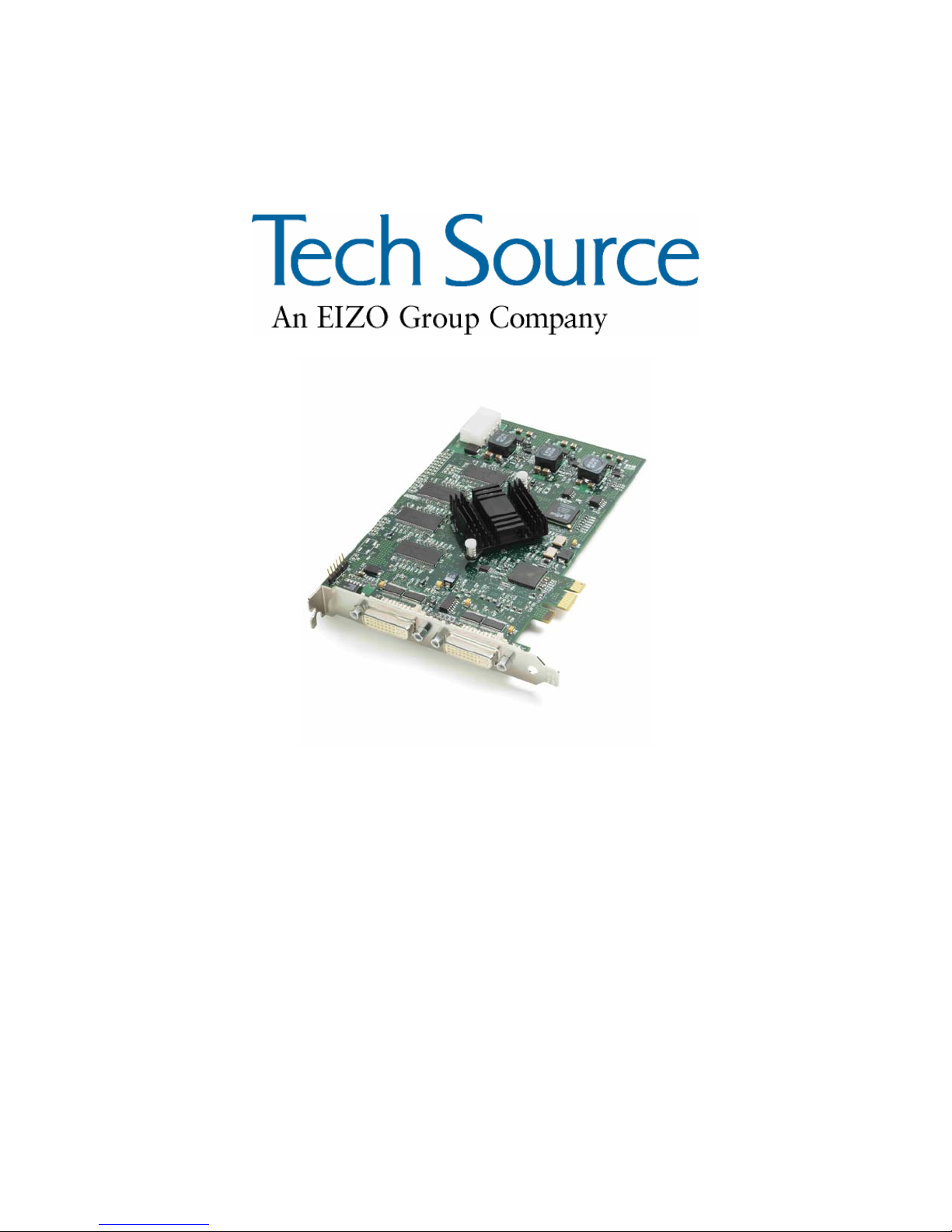
Thank you for purchasing a Tech Source, Inc. Raptor graphics
card for use with your x86 PC workstation/server. This manual
describes the installation and configuration of the Raptor
graphics card and the Linux drivers for the Raptor 4000 Series
product.
This software runs on x86 PC workstations/servers and supports
kernel versions 2.4 and 2.6. For support of another kernel,
please contact Tech Source at: hotline@techsource.com.
The following products are supported:
• Raptor 4000 Supports 2048x2048 resolutions (digital
and analog) on a PCI bus.
• Raptor 4000e Supports 2048x2048 resolutions (digital
and analog) on a PCI Express bus.
• Raptor 4000-LR Supports 1920x1200 resolutions (DVISingle Link digital and analog) on a PCI
bus.
• Raptor 4000e-LR Supports 1920x1200 resolutions (DVI-
Single Link digital and analog) on a PCI
Express bus.
• Raptor 4000-R Supports 2048x2048 resolutions (digital
and analog) with hardware rotation on a
PCI bus.
• Raptor 3500e Supports 2048x2048 resolutions (digital
only) on a PCI Express bus.
©2009 Tech Source Inc. 1 Part #65-0271-01
Page 8
Raptor 4000 Series: Reference Manual
The Raptor 4000 Series drivers for Linux are provided on a CDROM which consists of:
• Tech Source Raptor device drivers for Linux
• Loadable DDX modules for Tech Source Raptor cards.
• MOX extension files
• TSIMISC extension files
NOTE: In order to use the Tech Source Raptor DDX module,
you must have XFree86 (v4.0 or later) previously installed.
All systems vary somewhat, therefore some knowledge of the
features of your system and a basic understanding of UNIX shell
commands are helpful during the software installation process.
A hardware specification for each of these cards is listed in
Appendix A. From this point forward, Tech Source, Inc. will be
referred to as Tech Source or TSI.
This manual will follow certain conventions throughout.
Whenever a variable name, command name, directory, or
filename is used in a paragraph, it will appear in a mono-
spaced font.
At times the reader will be instructed to enter commands at a
prompt. In this case a transcript of a sample session will be
provided where a prompt will be followed by the commands the
reader is to enter. The entire transcript will be in a mono-
spaced font with the prompt in a normal weight and the user's
entries in bold.
The prompt used in a transcript varies depending on the
circumstances. The following are some common prompts and
when they are used:
prompt# used when the user is required to have root
privileges
prompt% used when the user is not required to have root
privileges
©2009 Tech Source Inc. 2 Part #65-0271-01
Page 9
Raptor 4000 Series: Reference Manual
2 Hardware Installation
2.1 Hardware Configurations Supported
The Raptor card and software accompanying this manual have
been tested on Intel and AMD x86 based computer systems
running Linux. By default, video will display on the head nearest
to the PCI bus. This is the high resolution head which also
supports the MOX feature. The low resolution head is the one
furthest from the PCI bus.
In addition to supporting a single screen environment, each
Raptor 4000 Series card has dual head capability to support
multi-screen configurations. Each head on the card can co-exist
with the other and display distinct screens.
Raptor cards use loadable drivers and can co-exist in multiscreen configurations with other VGA/SVGA graphics cards,
provided drivers are available for those cards under XFree86.
NOTE: Raptor 4000 Series cards currently cannot be used to
display console video in a PC. You must install a VGA/SVGA
PC video card from another manufacturer for this purpose.
2.2 Installation Instructions
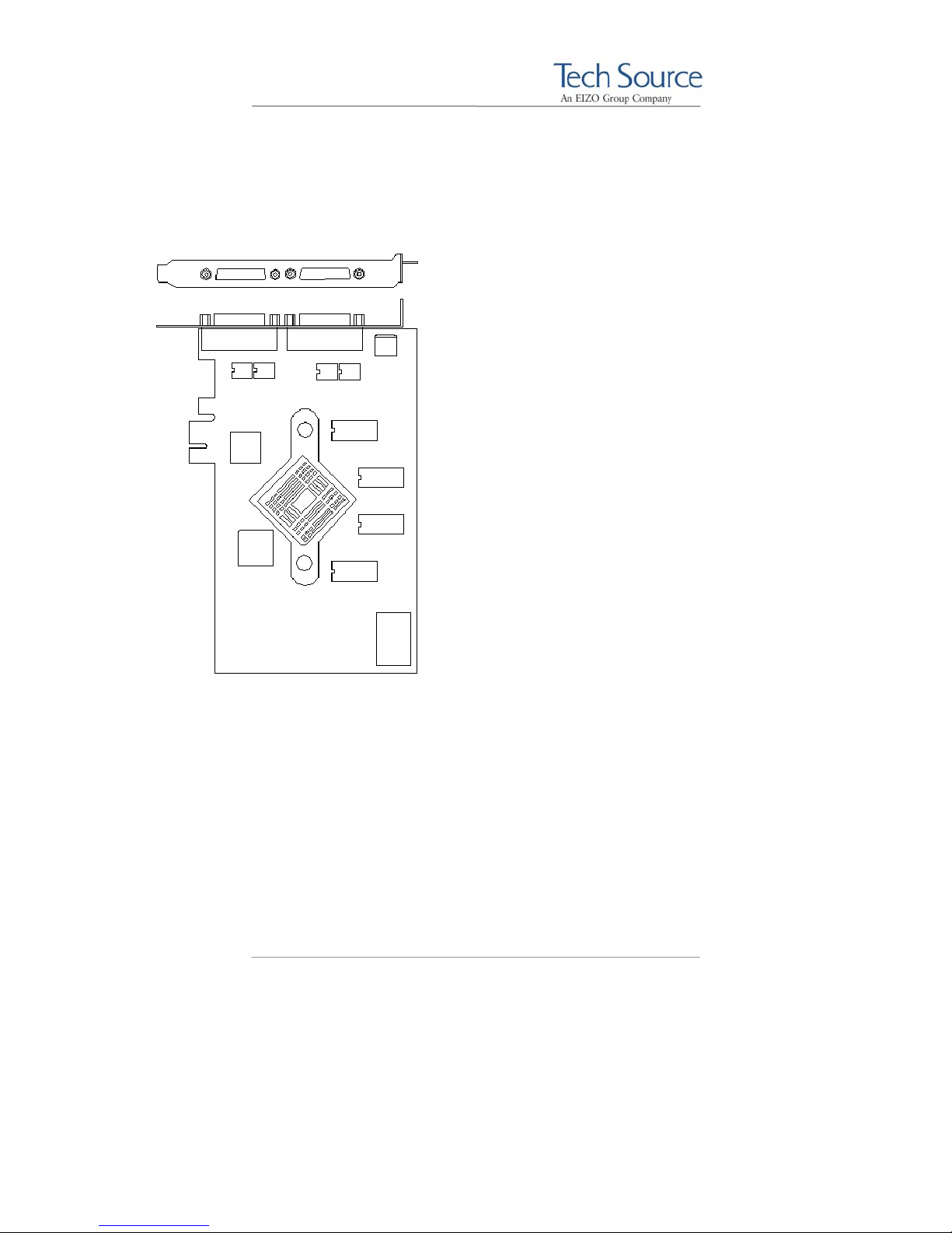
The Raptor graphics card installation is simple and consists of a
few easy steps. Prior to installation, be sure to terminate the X
Server.
NOTE: Remember which cables go to which connectors.
You may want to label the cables and connectors before
disconnecting them.
Step 1: Shut down the system and turn the power OFF.
Remove the system's cover, then find an
©2009 Tech Source Inc. 3 Part #65-0271-01
Page 10

Raptor 4000 Series: Reference Manual
available PCI slot, and remove the bracket and
screw. Ground yourself by touching the metal
part on an unpainted section of the metal case.
Step 2: Install the Raptor graphics card firmly into the
PCI slot. Take care to press it evenly and
snugly into the slot. Once you are certain the
card is installed properly in the slot, secure it
with the bracket screw.
Step 3: Secure the system cover, attach any previously
removed cables, and connect the video cable
card to your monitor.
The Raptor graphics card is now installed and the system is
ready for software installation. Please refer to Chapter 3 for
installing and configuring the software.
©2009 Tech Source Inc. 4 Part #65-0271-01
Page 11

Raptor 4000 Series: Reference Manual
3 Software Installation
3.1 Overview
This installation chapter describes how to install and configure the
drivers for Raptor 4000 Series cards. The following card models
are supported:
• Raptor 4000
• Raptor 4000e
• Raptor 4000-LR
• Raptor 4000e-LR
• Raptor 4000-R
Henceforth, Raptor 3500e will be referred to as Raptor 4000
Series product.
3.2 Requirements
The following are prerequisites for installing the Raptor Drivers for
Linux Software:
• At least 3MB of disk space available in “/” and “/usr” for
• A Raptor card is presently installed in the workstation/server
• Linux Kernel v2.4.x or v2.6.x installed
• XFree86 (v4.0 or later) or X.org distribution installed and
• RPM (v3.0 or later) packaging tools
Updates or recompiles to the kernel, X.org or XFree86 distribution
may cause the driver and DDX to fail to load. In this event, please
contact our technical support team for a possible solution (See
Chapter 7).
• Raptor 3500e
drivers.
(See Chapter 2 for instructions on installing a Raptor graphics
card).
configured for the current console graphics card
©2009 Tech Source Inc. 5 Part #65-0271-01
Page 12
Raptor 4000 Series: Reference Manual
The software consists of the following modules:
rapafp.o Kernel driver for the Raptor 4000 series
rapafp_drv.o Loadable DDX module
libMOX.a MOX extension module
libTSIMISC.a TSIMISC extension module
3.3 CD-ROM Installation
NOTE: Rebooting the system after the Raptor card installation
may cause the auto configuration manager to come up in some
distributions. At this point, ignore the auto configuration. Refer
to Section 3.8 to configure the Raptor card after the software is
installed.
3.3.1 Step-by-Step Installation Instructions
The following are step by step instructions for installing the Raptor
Drivers for Linux from a CD-ROM.
1. Login as root on the target system, using /bin/sh as
your shell.
2. Insert the CD-ROM labeled “Raptor Drivers for Linux” into
the drive.
3. If the drive is already mounted, the following directories
will contain the Raptor Drivers for Linux:
For kernel 2.4, type:
prompt# cd /mnt/cdrom/linux_2.4/
For kernel 2.6, type:
prompt# cd /mnt/cdrom/linux_2.6/
©2009 Tech Source Inc. 6 Part #65-0271-01
Page 13

Raptor 4000 Series: Reference Manual
4. If the CD-ROM is not already mounted, type:
prompt# mount /dev/cdrom /mnt/cdrom
Type the appropriate command as outlined in step 3.
5. The packages are in Red Hat's RPM format. For
information on downloading, installing, and using the RPM
utility, please refer to Red Hat's website and the related
FAQ and HOWTO.
To install the driver package on kernel 2.4, type:
prompt# rpm -Uvh rapafp-*.rpm
To install the driver package on kernel 2.6, type:
prompt# rpm -Uvh rapafp6-*.rpm
6. Reboot the system to make sure the drivers will be
reloaded.
7. To verify that the device drivers were loaded correctly,
type:
prompt# cat /proc/modules | grep rapafp
The output should show the entry for the Raptor device
drivers similar to the following:
rapafp_mod 39152 0 – Live 0xf8bbf000
8. To install the MOX package, type:
prompt# cd /mnt/cdrom/mox/
prompt# rpm -Uvh tsimox-*.rpm
©2009 Tech Source Inc. 7 Part #65-0271-01
Page 14
Raptor 4000 Series: Reference Manual
9. To install the TSIMISC package, type:
prompt# cd /mnt/cdrom/tsimisc/
prompt# rpm -Uvh tsimisc-*.rpm
NOTE: You must install the MOX package if you plan on running
the card(s) in MOX mode. Also note, that the Raptor 3500e does
not support MOX mode.
3.3.2 Using the install_all Installation Script
For ease of use, a script has been provided to install all available
packages including the Raptor 4000 series software drivers, and
all software extensions such as TSIMISC and MOX.
1. Refer to steps 1 through 4 in the step-by-step instructions
for mounting the CD ROM and selecting the appropriate
kernel version.
2. After the kernel version directory has been selected, type:
prompt# ./install_all
This script installs all available packages for the Raptor 4000
series boards.
3.4 MOX Extension Support
Tech Source provides and supports an X server extension called
MOX (Multiple Overlay eXtension). Software support for MOX is
provided by a server extension and a client library, which are
included with this product.
©2009 Tech Source Inc. 8 Part #65-0271-01
Page 15

Raptor 4000 Series: Reference Manual
Installation and configuration of MOX software is discussed
throughout this chapter. The MOX software must be installed only
once. The software can be found in the MOX directory on the
cdrom. In the example below, the MOX software automatically
modifies the “Module” Section in the xorg.conf file.
Section "Module"
Load "dbe"
Load "extmod"
Load "MOX" # TSI MOX Extension
Load "fbdevhw"
Load "glx"
Load "record"
Load "freetype"
Load "type1"
Load "dri"
EndSection
For more information about MOX, please contact Tech Source for
a technical white paper.
3.5 TSIMISC Extension Support
This extension provides various additional functionalities that are
not included within the regular Xserver. Current implementation of
TSIMISC extension enables a user to constrain the cursor to a
particular screen.
The software can be found in the tsimisc directory on the cdrom.
Upon installation of extension package the xorg.conf file gets
updated so that the TSIMISC extension is loaded when the X
server starts. In the example below, the TSIMISC software
automatically modifies the “Module” Section in the xorg.conf
file.
©2009 Tech Source Inc. 9 Part #65-0271-01
Page 16
Raptor 4000 Series: Reference Manual
Section "Module"
Load "dbe"
Load "extmod"
Load "MOX" # TSI MOX Extension
Load "TSIMISC" # TSIMISC Extension
Load "fbdevhw"
Load "glx"
Load "record"
Load "freetype"
Load "type1"
Load "dri"
EndSection
For more information about TSIMISC please contact Tech Source
for a technical white paper.
3.6 New Device
Upon initial installation of a Raptor 4000 series card, new device
names are created in the /dev directory for each head. It is
denoted by rapafp# for each card where # represents an
instance number assigned by the operating system.
For example, /dev/rapafp0 is the first head seen by the system,
/dev/rapafp1 will be the second head seen by the system.
NOTE: Only the first “Device” and “Screen” sections are
automatically added to the “xorg.conf” file by the Raptor 4000
series installation software. Subsequent relocation(s) of the first
Raptor 4000 card and/or additional Raptor 4000 cards being
added to the system will require the user to manually add and
configure these sections to the “xorg.conf” file per device
instance. See section 4.5 for more details.
©2009 Tech Source Inc. 10 Part #65-0271-01
Page 17
Raptor 4000 Series: Reference Manual
3.7 DDC Resolution
NOTE: From this point the name xorg.conf will be used to refer
to the configuration file used by both the XFree86 and X.org
server.
If you are using a monitor with DDC2B/EDID protocol the default
resolution will be determined using the Auto-Detect feature. With
this protocol, the Raptor 4000 Series card first checks the Detailed
Timing and Established Timing Identifiers (taking the first one
supported) and then tries to match the Standard Timings.
NOTE: The monitor must be turned ON prior to starting the
Xserver in order for a Raptor card to pick up and use the default
monitor resolution. Some adapters and cables may block this
signal.
By default, the X server will start with the resolution that DDC has
reported. If the Auto-Detect feature fails the card will use the
resolution specified in the “Screen” Section for the associated
“Device” in the xorg.conf file.
Other methods described in this section will override any
information obtained via EDID.
If the monitor is not DDC capable, then the Xserver will start with
the resolution that is specified in the xorg.conf file. Please refer
to section 4.7 for details on how to modify resolutions in the
xorg.conf file, and section 4.7.2 on how to disable DDC.
3.8 Configuration for PC Graphics Hardware
This section assumes that the XF86Config or xorg.conf file
was configured to work properly with your existing VGA/SVGA
cards. For documentation on how to install and configure your
VGA/SVGA card, please refer to the XFree86 documentation.
©2009 Tech Source Inc. 11 Part #65-0271-01
Page 18
Raptor 4000 Series: Reference Manual
After installing the Raptor drivers, five sections will be
automatically added to the xorg.conf file. The “Monitor”
section will be added followed by separate “Device” and
“Screen” sections for each head for a total of five sections.
If your system is using a different configuration file than the
xorg.conf file, you may need to configure your file with the
necessary sections for each head from:
/etc/X11/XF86Config.rapafp
NOTE: If more than one Raptor 4000 Series card is installed, only
the first card will be configured automatically. Subsequent card(s)
must be configured manually. Each Device section must have a
unique Identifier, BusID and Device option field. For more
information on multi-screen environment refer to Section 4.5.
An example configuration of a Raptor 4000 Series card is listed
below. The Identifier for the Raptor 3500e will be different.
The required modifications are explained in greater detail in the
following pages.
# TSI Raptor 4000 Configuration Sections
Section "Monitor"
Identifier "TSI-FP DVI"
VendorName "Tech Source, Inc"
HorizSync 31.5 - 150.0
VertRefresh 50-90
ModeLine "2048x2048" 260.00 2048 2112 2176 2304
2048 2051 2057 2116
ModeLine "2560x2048" 292.40 2560 2592 2608 2672
2048 2049 2050 2055
ModeLine "2048x2048_D" 255.92 2048 2080 2112
2176 2048 2053 2056 2079
EndSection
Section "Device"
Identifier "Rapafp0"
Driver "rapafp"
BusID "PCI:41:0:0"
Card "TSI Raptor 4000"
Option "Device" "/dev/rapafp0"
Option "Mode" "24"
Option "ScaleCursPos" "on"
Screen 0
Option "Head" "0"
©2009 Tech Source Inc. 12 Part #65-0271-01
Page 19

Raptor 4000 Series: Reference Manual
# Option "DDCCheck" "off"
# Option "Rotation" "+r"
# Option "Sync" "sx"
# Option "BackingStore"
# Option "SaveUnder"
# Option "TranspColor" "0x0a3246"
EndSection
Section "Screen"
Identifier "Raptor4000-0"
Device "Rapafp0"
Monitor "TSI-FP DVI"
DefaultDepth 24
SubSection "Display"
Depth 8
Modes "2048x2048"
EndSubSection
SubSection "Display"
Depth 16
Modes "2048x2048"
EndSubSection
SubSection "Display"
Depth 24
Modes "2048x2048"
EndSubSection
EndSection
# TSI Raptor 4000 Configuration Sections
Section "Device"
Identifier "Rapafp1"
Driver "rapafp"
BusID "PCI:41:0:0"
Card "TSI Raptor 4000"
Option "Device" "/dev/rapafp1"
Option "Mode" "24"
Option "ScaleCursPos" "on"
Screen 1
Option "Head" "1"
# Option "Sync" "sx"
# Option "BackingStore"
# Option "SaveUnder"
# Option "TranspColor" "0x0a3246"
EndSection
Section "Screen"
Identifier "Raptor4000-1"
Device "Rapafp1"
Monitor "TSI-FP DVI"
DefaultDepth 24
SubSection "Display"
Depth 8
Modes "2048x2048"
EndSubSection
©2009 Tech Source Inc. 13 Part #65-0271-01
Page 20
Raptor 4000 Series: Reference Manual
SubSection "Display"
Depth 16
Modes "2048x2048"
EndSubSection
SubSection "Display"
Depth 24
Modes "2048x2048"
EndSubSection
EndSection
# TSI Raptor 4000 Configuration Sections
3.8.1 Monitor Section
This section contains default configuration information for the
monitor and should remain unchanged.
3.8.2 Device Section
Identifier: Each instance of a Raptor card should have a
unique identifier. This identifier is used in the
Screen section.
NOTE: The BusID value in the configuration file will be updated
automatically during software installation. The BusID will need to
be updated manually for additional Raptor Series cards or slot
changes. Please see the description below for details.
BusID: Depending on the machine and the slot the
card is in, it might receive a unique BusID.
When the driver attaches, it will print out the
device name and BusID. To check the
BusID, type dmesg|grep rapafp. The
In the example above, the Raptor 4000 has a
output should look similar to the following:
TSI: rapafp0 (BusID 41:0:0) is
RAPTOR 4000 @ 1280x1024
TSI: rapafp1 (BusID 41:0:0) is
RAPTOR 4000 @ 2048x2048.
©2009 Tech Source Inc. 14 Part #65-0271-01
Page 21

Raptor 4000 Series: Reference Manual
BusID of PCI:41:0:0. If you are
experiencing a problem starting the Xserver,
please verify the BusID of the card in
xorg.conf match the BusID reported by
the system.
Option "Device": This field specifies the device name assigned
to each head on the Raptor 4000 Series card.
The first head seen by the system will be
/dev/rapafp0 and the second will be
/dev/rapafp1.
Option "Mode": This field specifies pixel modes.
8 8-bit PsuedoColor
24 24-bit True Color
8+8 Two 8-bit PseudoColor visuals
8+24 8-bit PseudoColor & 24 bit True Color visuals
mox24 MOX, 8-bit Normal, 21-bit Group, 13-bit
Absolute
mox32 MOX, 8-bit Normal, 24-bit Group, 21-bit
Absolute
ScaleCursPos This Boolean field option is useful when
monitors of different screen sizes are used
together in a multi-screen configuration. When
the cursor crosses screen boundaries, its
position on the new screen will be adjusted to
be proportional to where it was on the
previous screen.
Sync This field option is used to override DDC info.
The xorg.conf resolution line is used to
drive only digital panels. For an analog signal,
this field should be commented out.
TranspColor This field option is only used while in 8+8
mode. It allows the user to specify the RGB
color values associated with the transparent
color of the overlay. If an application is
©2009 Tech Source Inc. 15 Part #65-0271-01
Page 22

Raptor 4000 Series: Reference Manual
mistakenly using the transparent color, the
value of the color can be changed so that the
application no longer uses it. The default
value is 0x0A3246.
3.8.3 Screen Section
Identifier: Each screen must have a unique identifier
which will be used in the ServerLayout
Device: This field specifies which device you want to
Monitor: This field should remain unchanged for the
DefaultDepth: Should be set to 24 bit depth.
Modes: This field should specify the desired
The following sample screen section shows the 4000 Series card,
which is configured for 2048x2048:
Section "Screen"
Identifier "Raptor4000-0"
Device "Rapafp0"
Monitor "TSI-FP DVI"
DefaultDepth 24
SubSection "Display"
Depth 8
Modes "2048x2048"
EndSubSection
section.
use for this screen. It should match the
Identifier specified in one of the Device
sections.
Raptor 4000 Series cards. Refer to the
XFree86 or X.org documentation for
instructions on how to create a custom
Monitor section.
resolution. If DDC2B/EDID is present, this field
is ignored.
©2009 Tech Source Inc. 16 Part #65-0271-01
Page 23

Raptor 4000 Series: Reference Manual
SubSection "Display"
Depth 16
Modes "2048x2048"
EndSubSection
SubSection "Display"
Depth 24
Modes "2048x2048"
EndSubSection
EndSection
# TSI Raptor 4000 Configuration Sections
Section "Screen"
Identifier "Raptor4000-1"
Device "Rapafp1"
Monitor "TSI-FP DVI"
DefaultDepth 24
SubSection "Display"
Depth 8
Modes "2048x2048"
EndSubSection
SubSection "Display"
Depth 16
Modes "2048x2048"
EndSubSection
SubSection "Display"
Depth 24
Modes "2048x2048"
EndSubSection
EndSection
3.8.4 Server Layout Section
This is the section which specifies the server layout for either
single-screen or multi-screen configuration.
NOTE: The ServerLayout section should already exist in
your xorg.conf file. This section must be modified
manually to include the Raptor card.
The following example shows the ServerLayout Section for a
single-screen configuration on the Raptor 4000 Series device.
Section "ServerLayout"
Identifier "XFree86 Configured"
Screen 0 "Raptor4000-0" 0 0
©2009 Tech Source Inc. 17 Part #65-0271-01
Page 24

Raptor 4000 Series: Reference Manual
InputDevice "Mouse0" "CorePointer"
InputDevice "Keyboard0" "CoreKeyboard"
EndSection
The following example shows the ServerLayout Section for a
single-screen configuration on the Raptor 3500e device.
Section "ServerLayout"
Identifier "XFree86 Configured"
Screen 0 "Raptor3500-0" 0 0
InputDevice "Mouse0" "CorePointer"
InputDevice "Keyboard0" "CoreKeyboard"
EndSection
Assuming Screen0 is the console card, the following example
shows the ServerLayout section with the Raptor Series card as
the second screen.
Section "ServerLayout"
Identifier "XFree86 Configured"
Screen 0 "Screen0" LeftOf "Raptor4000-0"
Screen 1 "Raptor4000-0" RightOf "Screen0"
InputDevice "Mouse0" "CorePointer"
InputDevice "Keyboard0" "CoreKeyboard"
EndSection
Assuming Screen0 is the console card, the following example
shows the ServerLayout section with the Raptor 3500e card as
the second screen.
Section "ServerLayout"
Identifier "XFree86 Configured"
Screen 0 "Screen0" LeftOf "Raptor3500-0"
Screen 1 "Raptor3500-0" RightOf "Screen0"
InputDevice "Mouse0" "CorePointer"
InputDevice "Keyboard0" "CoreKeyboard"
EndSection
©2009 Tech Source Inc. 18 Part #65-0271-01
Page 25

Raptor 4000 Series: Reference Manual
4 Invoking the X Server
4.1 Overview
There are several ways to invoke the X server on your system:
• startx script provided in /usr/X11R6/bin
• xinit
• xdm
This section assumes the use of the csh environment. If you
prefer a different shell, make the appropriate changes to the
examples.
NOTE: For all these methods, there are some
environment variables that must be set. These variables
can be set in your .cshrc file.
prompt% setenv X11R6HOME /usr/X11R6
prompt% setenv LD_LIBRARY_PATH \
$X11R6HOME/lib
prompt% set path=($X11R6HOME/bin $path)
All of the options specific to the Tech Source Raptor graphics
accelerators are set through the option field in the Device section
of the xorg.conf file. No command-line options are necessary
when using startx, xinit or xdm to start the X server. Refer to
Chapter 3 for instructions on how to properly configure the
xorg.conf files.
NOTE: For changes to take effect, the Xserver must be restarted
after modifications are made to the X configuration file.
©2009 Tech Source Inc. 19 Part #65-0271-01
Page 26

Raptor 4000 Series: Reference Manual
4.2 startx
The startx script is provided in $X11R6HOME/bin directory. To
start up the X server in the default mode type:
prompt% startx
You may add any other standard command line arguments to the
end of the line as necessary.
4.3 xinit
The xinit program can be used to start the X server directly. The
xinit format is as follows:
xinit [[client] options][ -- [server] [display] options ]
If no specific client program is given on the command line, xinit
will look for a file in the user's home directory called .xinitrc to
run as a shell script to start up client programs. If no such file
exists, xinit will use the following as a default:
If no specific server program is given on the command line, xinit
will look for a file in the user's home directory called .Xserverrc
to run as a shell script to start up the server. If no such file exists,
xinit will use the following as a default:
This assumes that there is a program named X in the current
search path. The X server in the XFree86 4.0 (or later) distribution
is called XFree86 and is in the directory $X11R6HOME/bin. A
symbolic link has been made from X to XFree86. The X server in
the X.org distribution is called Xorg and is in the directory
$X11R6HOME/bin. A symbolic link has been made from X to
Xorg.
xterm -geometry +1+1 -n login \
-display :0
X :0
©2009 Tech Source Inc. 20 Part #65-0271-01
Page 27

Raptor 4000 Series: Reference Manual
NOTE: Make sure that the environment is set as described in
Section 4.1.
To start up the server using xinit, type:
prompt% xinit -- $X11R6HOME/bin/X
You may also add any other standard command line arguments to
the end of the line. For additional information on the use of xinit,
refer to the xinit man page.
4.4 xdm
The X Display Manager (xdm) program is used for running multiple
users on the same host machine. xdm provides services similar to
those provided by init, getty and login on character terminals
prompting for login name and password, authenticating the user,
and running a session. It provides a login window for each user or
selected users.
Several files that are required to start xdm are provided in the
directory /etc/X11/xdm (depending on the distribution on your
system, the path to these files might be different). The
configuration file, xdmconfig, contains references to the other
files and is used to specify other configuration parameters of xdm.
The Xservers file specifies the users (displays) that must get a
login window.
The Xservers file will have individual lines to represent the X
server startup on each of the display devices on which an xdm
login screen is desired. Once the configuration file is properly
configured, a typical Xservers file should contain only one
uncommented line, such as the following example:
:0 local /usr/X11R6/bin/X
Other command line arguments may be added to end of the line.
For more information on xdm, refer to the xdm man pages.
©2009 Tech Source Inc. 21 Part #65-0271-01
Page 28

Raptor 4000 Series: Reference Manual
4.5 Configuring the X Server for Multi-Screen
Mode
4.5.1 Configurations for Multiscreen Mode
The xorg.conf (configuration) file determines whether the X
server starts up in single-screen or multi-screen mode. Desired
configurations must first be set. Once the configuration file is
correctly set up, the procedure for starting the X server (whether in
single-screen or multi-screen mode) will be the same.
To start the X server in multi-screen mode, changes need to be
made to the ServerLayout, Device and Screen sections.
Each Raptor card has its own Device and Screen section.
These sections in the xorg.conf file are added once during
driver installation and will need to be added manually for each
additional 4000 Series card installed.
For multiscreen mode, the ServerLayout section in xorg.conf
needs to be modified.
In the Screen section of the xorg.conf file, the fields that need
to be changed are: Identifier and Device. The
Identifier option for Screen1 (head1) is Raptor4000-1. The
Device option is labeled, “Rapafp1”. This will differentiate this
head from another in the ServerLayout section.
Section "ServerLayout"
Identifier "XFree86 Configured"
Screen 0 "Raptor4000-0"
Screen 1 "Raptor4000-1" LeftOf “Raptor4000-0”
InputDevice "Mouse[1]" "CorePointer"
InputDevice "Keyboard[0]" "CoreKeyboard"
EndSection
In the example above, the Xserver will start on both heads of the
4000 card, Screen0 (head0) and Screen1 (head1).
©2009 Tech Source Inc. 22 Part #65-0271-01
Page 29

Raptor 4000 Series: Reference Manual
NOTE: If you are using a Raptor 3500e then the Identifier
will be Raptor3500-0 in the ServerLayout Section.
In the example below, the sections related to Screen0 and
Screen1 are provided. To change the resolution on Screen1
(head1), the new resolution will need to be specified to the Modes
option in the Screen section.
Section "Device"
Identifier "Rapafp0"
Driver "rapafp"
BusID "PCI:17:0:0"
Card "TSI Raptor 4000"
Option "Device" "/dev/rapafp0"
Option "Mode" "24"
Option "ScaleCursPos" "on"
Screen 0
Option "Head" "0"
# Option "DDCCheck" "off"
# Option "Rotation" "+r"
# Option "Sync" "sx"
# Option "BackingStore"
# Option "SaveUnder"
# Option "TranspColor" "0x0a3246"
EndSection
Section "Screen"
Identifier "Raptor4000-0"
Device "Rapafp0"
Monitor "TSI-FP DVI"
DefaultDepth 24
SubSection "Display"
Depth 8
Modes "2048x2048"
EndSubSection
SubSection "Display"
Depth 16
Modes "2048x2048"
EndSubSection
SubSection "Display"
Depth 24
Modes "2048x2048"
EndSubSection
EndSection
©2009 Tech Source Inc. 23 Part #65-0271-01
Page 30

Raptor 4000 Series: Reference Manual
Section "Device"
Identifier "Rapafp1"
Driver "rapafp"
BusID "PCI:17:0:0"
Card "TSI Raptor 4000"
Option "Device" "/dev/rapafp1"
Option "Mode" "24"
Option "ScaleCursPos" "on"
Screen 1
Option "Head" "1"
# Option "DDCCheck" "off"
# Option "Sync" "sx"
# Option "BackingStore"
# Option "SaveUnder"
# Option "TranspColor" "0x0a3246"
EndSection
Section "Screen"
Identifier "Raptor4000-1"
Device "Rapafp1"
Monitor "TSI-FP DVI"
DefaultDepth 24
SubSection "Display"
Depth 8
Modes "2048x2048"
EndSubSection
SubSection "Display"
Depth 16
Modes "2048x2048"
EndSubSection
SubSection "Display"
Depth 24
Modes "2048x2048"
EndSubSection
EndSection
NOTE: The BusId and Device for each card is determined
by running dmesg | grep rapafp.
NOTE: In the Screen section of a given Raptor card, the
Device field must match the Identifier field specified in
the corresponding Device section.
Section "Screen"
Identifier "Raptor4000-1"
Device "Rapafp1"
Monitor "TSI-FP DVI"
©2009 Tech Source Inc. 24 Part #65-0271-01
Page 31

Raptor 4000 Series: Reference Manual
DefaultDepth 8
SubSection "Display"
Depth 8
Modes "2048x2048_D"
EndSubSection
SubSection "Display"
Depth 16
Modes "2048x2048_D"
EndSubSection
SubSection "Display"
Depth 24
Modes "2048x2048_D"
EndSubSection
EndSection
To change the resolution for each device, please refer to Section
4.7.
4.5.2 Defining Order of Display
The order of appearance for the display of two cards can be
configured in the xorg.conf file. In the example given below, the
display of the primary card is specified to be on the left of the
secondary card.
Assuming Screen0 is the console card, the following example
shows the ServerLayout section with the Raptor 4000 Series
card as the secondary screen.
Section "ServerLayout"
Identifier "Default Layout"
Screen 0 "Screen0" LeftOf "Raptor4000-0"
Screen 1 "Raptor4000-0" RightOf "Screen0"
InputDevice "Mouse0" "CorePointer"
InputDevice "Keyboard0" "CoreKeyboard"
EndSection
©2009 Tech Source Inc. 25 Part #65-0271-01
Page 32

Raptor 4000 Series: Reference Manual
4.6 Selecting Bit-Depths on 4000 Series
Cards
4.6.1 Setting Bit-Depth
The 4000 Class cards support 8-bit, 24 bit, 8+8, 8+24,
mox24 and mox32 modes. By default, windows will start in 24bit mode on these cards. For an explanation of the various MOX
modes, please see Section 4.6.2.
NOTE: The Raptor 3500e does not support 8+8, 8+24 modes
or any of the MOX modes.
To set bit-depth to 8-bit, the "Mode" option in the Device section
needs to be set to “8” and the other values should remain
unchanged.
To set bit-depth to 24, the "Mode" option should be set to "24":
Section "Device"
Identifier "Rapafp0"
Driver "rapafp"
BusID "PCI:41:0:0"
Card "TSI Raptor 4000"
Option "Device" "/dev/rapafp0"
Option "Mode" "8"
Option "ScaleCursPos" "on"
Screen 0
Option "Head" "0"
# Option "DDCCheck" "off"
# Option "Rotation" "+r"
# Option "Sync" "sx"
# Option "BackingStore"
# Option "SaveUnder"
# Option "TranspColor" "0x0a3246"
EndSection
Section "Device"
Identifier "Rapafp0"
Driver "rapafp"
BusID "PCI:41:0:0"
Card "TSI Raptor 4000"
Option "Device" "/dev/rapafp0"
Option "Mode" "24"
©2009 Tech Source Inc. 26 Part #65-0271-01
Page 33

Raptor 4000 Series: Reference Manual
Option "ScaleCursPos" "on"
Screen 0
Option "Head" "0"
# Option "DDCCheck" "off"
# Option "Rotation" "+r"
# Option "Sync" "sx"
# Option "BackingStore"
# Option "SaveUnder"
# Option "TranspColor" "0x0a3246"
EndSection
To select 8+8-bit mode, the "Mode" option in the Device
section should be set to “8+8” and the “TranspColor” option
should be uncommented. In the Screen section, the default depth
should be set to “8”.
Section "Device"
Identifier "Rapafp0"
Driver "rapafp"
BusID "PCI:41:0:0"
Card "TSI Raptor 4000"
Option "Device" "/dev/rapafp0"
Option "Mode" "8+8"
Option "ScaleCursPos" "on"
Screen 0
Option "Head" "0"
# Option "DDCCheck" "off"
# Option "Rotation" "+r"
# Option "Sync" "sx"
# Option "BackingStore"
# Option "SaveUnder"
Option "TranspColor" "0x0a3246"
EndSection
Section "Screen"
Identifier "Raptor4000-0"
Device "Rapafp0"
Monitor "TSI-FP DVI"
DefaultDepth 8
SubSection "Display"
Depth 8
Modes "2048x2048"
EndSubSection
SubSection "Display"
Depth 16
Modes "2048x2048"
EndSubSection
SubSection "Display"
Depth 24
Modes "2048x2048"
EndSubSection
EndSection
©2009 Tech Source Inc. 27 Part #65-0271-01
Page 34

Raptor 4000 Series: Reference Manual
The following example shows the 8+24 mode being selected for a
Raptor 4000 card. The "Mode" option is set to “8+24”.
Section "Device"
Identifier "Rapafp0"
Driver "rapafp"
BusID "PCI:41:0:0"
Card "TSI Raptor 4000"
Option "Device" "/dev/rapafp0"
Option "Mode" "8+24"
Option "ScaleCursPos" "on"
Screen 0
Option "Head" "0"
# Option "DDCCheck" "off"
# Option "Rotation" "+r"
# Option "Sync" "sx"
# Option "BackingStore"
# Option "SaveUnder"
# Option "TranspColor" "0x0a3246"
EndSection
The following example shows the mox24 mode being selected for
a Raptor 4000 card. The "Mode" option is set to “mox24”.
Section "Device"
Identifier "Rapafp0"
Driver "rapafp"
BusID "PCI:41:0:0"
Card "TSI Raptor 4000"
Option "Device" "/dev/rapafp0"
Option "Mode" "mox24"
Option "ScaleCursPos" "on"
Screen 0
Option "Head" "0"
# Option "DDCCheck" "off"
# Option "Rotation" "+r"
# Option "Sync" "sx"
# Option "BackingStore"
# Option "SaveUnder"
# Option "TranspColor" "0x0a3246"
EndSection
The following example shows the mox32 mode being selected for
a Raptor 4000 card. The "Mode" option is set to “mox32”.
Section "Device"
Identifier "Rapafp0"
Driver "rapafp"
BusID "PCI:41:0:0"
Card "TSI Raptor 4000"
Option "Device" "/dev/rapafp0"
©2009 Tech Source Inc. 28 Part #65-0271-01
Page 35

Raptor 4000 Series: Reference Manual
Option "Mode" "mox32"
Option "ScaleCursPos" "on"
Screen 0
Option "Head" "0"
# Option "DDCCheck" "off"
# Option "Rotation" "+r"
# Option "Sync" "sx"
# Option "BackingStore"
# Option "SaveUnder"
# Option "TranspColor" "0x0a3246"
EndSection
4.6.2 MOX Modes
MOX (Multiple Overlay Extension) provides support for multiple
drawing layers on graphics cards. MOX is available on all Raptor
cards with the exception of the Raptor 3500e card. Details about
MOX can be obtained in a technical white paper available
separately from Tech Source.
The following MOX modes are supported on the Raptor 4000
Series cards.
mox24 MOX, 8-bit Normal, 21-bit Group, 13-bit Absolute
mox32 MOX, 8-bit Normal, 32-bit Group, 24-bit Absolute
NOTE: MOX support is only available on the head closest to
the pci slot (Head0).
4.7 Setting Resolution on Raptor 4000 Series
Cards
By default, the Xserver will pick up the resolution specified by
DDC. If the attached monitor is not DDC capable, it will pick up the
resolution specified in the xorg.conf file.
©2009 Tech Source Inc. 29 Part #65-0271-01
Page 36

Raptor 4000 Series: Reference Manual
The resolution and refresh rate can be changed by modifying the
configuration file, such as the xorg.conf file.
The maximum supported resolution for each head on a Raptor
4000 Series can be found in Appendix B.
4.7.1 Setting Resolution
To override the provided DDC resolution in order to specify the
resolution you wish to display, refer to section 4.7.2.
To specify the resolution you wish to display, modify the "Modes"
option in the Screen section of the xorg.conf file. In the
SubSection “Display” listed beneath the DefaultDepth,
specify the new resolution in double quotes next to the Modes
option.
The example below represents the resolution set to 2048x2048. In
this case, the X server will automatically select the highest
possible refresh rate for the monitor.
Section "Screen"
Identifier "Raptor4000-0"
Device "Rapafp0"
Monitor "TSI-FP DVI"
DefaultDepth 24
SubSection "Display"
Depth 8
Modes "2048x2048"
EndSubSection
SubSection "Display"
Depth 16
Modes "2048x2048"
EndSubSection
SubSection "Display"
Depth 24
Modes "2048x2048"
EndSubSection
EndSection
©2009 Tech Source Inc. 30 Part #65-0271-01
Page 37

Raptor 4000 Series: Reference Manual
The example below represents the resolution set to 1280x1024. In
this case, the X server will automatically select the highest
possible refresh rate for the monitor.
Section "Screen"
Identifier "Raptor4000-0"
Device "Rapafp0"
Monitor "TSI-FP DVI"
DefaultDepth 24
SubSection "Display"
Depth 8
Modes "2048x2048"
EndSubSection
SubSection "Display"
Depth 16
Modes "2048x2048"
EndSubSection
SubSection "Display"
Depth 24
Modes "1280x1024"
EndSubSection
EndSection
If the monitor is not DDC capable, the option Sync in the Device
section should be uncommented so that the digital signal can be
used.
NOTE: If the monitor is using an analog signal, the Sync
option should remain commented out.
Section "Device"
Identifier "Rapafp0"
Driver "rapafp"
BusID "PCI:41:0:0"
Card "TSI Raptor 4000"
Option "Device" "/dev/rapafp0"
Option "Mode" "mox24"
Option "ScaleCursPos" "on"
Screen 0
Option "Head" "0"
# Option "DDCCheck" "off"
# Option "Rotation" "+r"
# Option "Sync" "sx"
# Option "BackingStore"
# Option "SaveUnder"
# Option "TranspColor" "0x0a3246"
EndSection
©2009 Tech Source Inc. 31 Part #65-0271-01
Page 38

Raptor 4000 Series: Reference Manual
The following “Screen” section shows the 4000 card configured
for use with the 2048x2048_D resolution:
Section "Screen"
Identifier "Raptor4000-0"
Device "Rapafp0"
Monitor "TSI-FP DVI"
DefaultDepth 24
SubSection "Display"
Depth 8
Modes "2048x2048_D"
EndSubSection
SubSection "Display"
Depth 16
Modes "2048x2048_D"
EndSubSection
SubSection "Display"
Depth 24
Modes "2048x2048_D"
EndSubSection
EndSection
# TSI Raptor 4000 Configuration Sections
Section "Screen"
Identifier "Raptor4000-1"
Device "Rapafp1"
Monitor "TSI-FP DVI"
DefaultDepth 24
SubSection "Display"
Depth 8
Modes "2048x2048_D"
EndSubSection
SubSection "Display"
Depth 16
Modes "2048x2048_D"
EndSubSection
SubSection "Display"
Depth 24
Modes "2048x2048_D"
EndSubSection
EndSection
# TSI Raptor 4000 Configuration Sections
If the desired resolution does not match a resolution in X server’s
internal list, it will be necessary to set both resolution and refresh
rate as explained in Section 4.7.3.
©2009 Tech Source Inc. 32 Part #65-0271-01
Page 39

Raptor 4000 Series: Reference Manual
4.7.2 Overriding DDC
If the monitor being used supports the DDC2B/EDID protocol, the
default resolutions will be determined using the Auto-Detect
feature. By default, the X server will start with the resolution that
DDC has reported. If the monitor is not DDC enabled, the
resolution defined in the xorg.conf file will be used.
To override or disable DDC mode, the “DDCCheck” “off”
option must be uncommented in the “Device” Section in the
xorg.conf file. It must be uncommented prior to starting the
Xserver for changes to take effect. By default, the “DDCCheck”
“off” option is commented out, so DDC is used.
When overriding DDC, the desired resolution should be defined in
the xorg.conf file. In addition, if you want to use a digital signal,
the option Sync in the Device section should also be
uncommented. To specify a particular resolution for your display,
refer to section 4.7.1.
In the example given below, the “DDCCheck” “off” option is
uncommented.
Section "Device"
Identifier "Rapafp0"
Driver "rapafp"
BusID "PCI:2:9:0"
Card "TSI Raptor 4000"
Option "Device" "/dev/rapafp0"
Option "Mode" "24"
Option "ScaleCursPos" "on"
Screen 0
Option "Head" "0"
Option "DDCCheck" "off"
# Option "Rotation" "+r"
# Option "Sync" "sx"
# Option "BackingStore"
# Option "SaveUnder"
# Option "TranspColor" "0x0a3246"
EndSection
©2009 Tech Source Inc. 33 Part #65-0271-01
Page 40

Raptor 4000 Series: Reference Manual
To enable DDC mode, the “DDCCheck” “off” option must be
commented out in the “Device” Section of your Raptor card.
This line option can be found in the xorg.conf file and must be
commented out prior to starting the Xserver.
In the example provided, Option “DDCCheck” “off” is
commented out, so DDC will be enabled.
Section "Device"
Identifier "Rapafp0"
Driver "rapafp"
BusID "PCI:2:9:0"
Card "TSI Raptor 4000"
Option "Device" "/dev/rapafp0"
Option "Mode" "24"
Option "ScaleCursPos" "on"
Screen 0
Option "Head" "0"
# Option "DDCCheck" "off"
# Option "Rotation" "+r"
# Option "Sync" "sx"
# Option "BackingStore"
# Option "SaveUnder"
# Option "TranspColor" "0x0a3246"
EndSection
4.7.3 Setting Mode Line
To select a specific mode line and refresh rate, both the Monitor
and the Screen sections of the configuration file need to be
modified. The configuration file used in the following example is
/etc/X11/xorg.conf. If the mode line you wish to use for you
display is not listed, then a list of supported resolutions along with
their corresponding timing numbers is available in the file
/etc/X11/rapafp_modeline.
©2009 Tech Source Inc. 34 Part #65-0271-01
Page 41

Raptor 4000 Series: Reference Manual
The example below shows how a user can configure their system
to use with most digital monitors.
To configure your desired resolution, you may need to extract the
necessary entry from /etc/X11/rapafp_modeline and insert it
into the Monitor section as shown in bold-face below.
Section "Monitor"
Identifier "TSI-FP DVI"
VendorName "Tech Source, Inc"
HorizSync 31.5 - 150.0
VertRefresh 40-90
ModeLine "2048x2048" 357.18 2048 2088 2408 2816
ModeLine "2048x2048_D" 255.92 2048 2080 2112 2176
ModeLine "2048x2048_T" 271.67 2048 2096 2104 2208
ModeLine "2560x2048" 292.40 2560 2592 2608 2672
EndSection
2048 2051 2054 2114
2048 2053 2056 2079
2048 2058 2061 2071
2048 2049 2050 2055
Next, the “Modes” option in the Screen section should be
changed to match the name listed in double quotations in the
ModeLine field of the Monitor section.
In the example below, the resolution is set to 2048x2048_D
which is the timing mode for use with most digital monitors.
Section "Screen"
Identifier "Raptor4000-0"
Device "Rapafp0"
Monitor "TSI-FP DVI"
DefaultDepth 24
SubSection "Display"
Depth 8
Modes "2048x2048_D"
EndSubSection
SubSection "Display"
Depth 16
Modes "2048x2048_D"
EndSubSection
SubSection "Display"
Depth 24
Modes "2048x2048_D"
EndSubSection
EndSection
©2009 Tech Source Inc. 35 Part #65-0271-01
Page 42

Raptor 4000 Series: Reference Manual
4.8 Rotation Mode Configuration
An option for screen rotation is available for the Raptor 4000R
board. Only the first head, the one closest to the PCI bus, will
support video for the rotator board.
To set the card in rotation mode, the "Rotation" option must
be uncommented in the “Device” Section in the xorg.conf
file. This option must be set prior to starting the Xserver. If this
option is commented out, then X Windows will be displayed in
regular, non rotated mode.
There are two rotation modes, clockwise and counterclockwise.
To start X Windows in clockwise rotated mode, set the
"Rotation" option to “+r” prior to starting the X server.
Observe the example below:
Section "Device"
Identifier "Rapafp0"
Driver "rapafp"
BusID "PCI:5:9:0"
Card "TSI Raptor 4000"
Option "Device" "/dev/rapafp0"
Option "Mode" "mox24"
Option "ScaleCursPos" "on"
Screen 0
Option "Head" "0"
# Option "DDCCheck" "off"
Option "Rotation" "+r"
# Option "Sync" "sx"
# Option "BackingStore"
# Option "SaveUnder"
# Option "TranspColor" "0x0a3246"
EndSection
©2009 Tech Source Inc. 36 Part #65-0271-01
Page 43

Raptor 4000 Series: Reference Manual
To start X Windows in counterclockwise rotated mode, set the
"Rotation" option to “-r” prior to starting the X server.
To display video in non-rotated mode, the "Rotation" option
must be commented in the “Device” Section of your rotation
card, as given in the example below.
Section "Device"
Identifier "Rapafp0"
Driver "rapafp"
BusID "PCI:5:9:0"
Card "TSI Raptor 4000"
Option "Device" "/dev/rapafp0"
Option "Mode" "mox24"
Option "ScaleCursPos" "on"
Screen 0
Option "Head" "0"
# Option "DDCCheck" "off"
# Option "Rotation" "+r"
# Option "Sync" "sx"
# Option "BackingStore"
# Option "SaveUnder"
# Option "TranspColor" "0x0a3246"
EndSection
©2009 Tech Source Inc. 37 Part #65-0271-01
Page 44

Raptor 4000 Series: Reference Manual
This page intentionally left blank.
©2009 Tech Source Inc. 38 Part #65-0271-01
Page 45

Raptor 4000 Series: Reference Manual
5 Uninstalling Software
5.1 Uninstalling the Software
To uninstall the software driver package:
For Kernel 2.4 type:
prompt# rpm -e rapafp
For Kernel 2.6 type:
prompt# rpm -e rapafp6
To uninstall the software extensions type:
prompt# rpm -e tsimox
prompt# rpm -e tsimisc
©2009 Tech Source Inc. 39 Part #65-0271-01
Page 46

Raptor 4000 Series: Reference Manual
This page intentionally left blank.
©2009 Tech Source Inc. 40 Part #65-0271-01
Page 47

Raptor 4000 Series: Reference Manual
6 Frequently Asked Questions
6.1 Frequently Asked Questions
When installing or configuring the Raptor 4000 Series software,
some questions, problems or concerns may arise. Some questions
frequently asked are listed below. If you need further assistance
with any questions or concerns not found in this section, please
contact our technical support group via:
hotline@techsource.com.
Q. Can the Raptor 4000 Series card be used to display
console video?
A. At this time, the Raptor 4000 Series card cannot be used
to display console video. A proper VGA card and driver
will need to be installed to display console video.
Q. When must I make modifications in order for a Raptor
4000 Series card to start on the X server?
A. Changing slots and adding new cards may require manual
modifications to the X configuration file. Any change in
default settings desired after the driver installation will
need to be manually done. Initial configuration of a Raptor
4000 Series card is done during the installation of the
driver and software. Please refer to Section 3.7 for details
on changing configuration settings.
Q. I am experiencing problems with display of my video.
What should I do?
A. Verify that you are using a monitor with a supported
resolution. The resolutions supported are mentioned in
©2009 Tech Source Inc. 41 Part #65-0271-01
Page 48

Raptor 4000 Series: Reference Manual
Appendix B. If your monitor and resolution are supported,
then look for any error messages pertaining to your Raptor
4000 Series device in /var/log/ Xorg.0.log. In the
log file, verify that the correct configuration file is being
used, in regards to any changes made. The line in the log
file will read something like, “(==) Using config file:
"/etc/X11/xorg.conf" If this is the correct
configuration file then next verify that the option in each of
the sections are correctly configured. The sections to be
verified are: “Server Layout” “Screen” “Display”
and “Monitor” Verify the BusID option matches the
BusID for the card. For further details, please refer to the
examples given in Chapter 3.
©2009 Tech Source Inc. 42 Part #65-0271-01
Page 49

Raptor 4000 Series: Reference Manual
7 Technical Assistance
7.1 Who to call for Help
If you need help, please call our Technical Support Team at (800)
330-8301, or directly at (407) 262-7100 between the hours of
9:30am - 5:30pm EST Monday through Friday.
Please have the software part number, version, and serial number
for your Raptor card(s) available when contacting Tech Source in
order to expedite support. Please make a note of this information
in the area below:
DETAILS OF YOUR CARD(S):
P/N: _________________________________
Model Name: ___________________________
Serial Number(s): ____________________
NOTE: Technical Assistance will be available only for
products under standard or extended warranty.
7.2 Email Address
Our email address is: hotline@techsource.com.
International customers may use email or our fax line at (407)339-
2554.
©2009 Tech Source Inc. 43 Part #65-0271-01
Page 50

Raptor 4000 Series: Reference Manual
7.3 Website
Detailed product information and Frequently Asked Questions
(FAQs), are available on our website located at:
http://www.techsource.com
©2009 Tech Source Inc. 44 Part #65-0271-01
Page 51

Raptor 4000 Series: Reference Manual
Appendix A Card Specifications
A.1 Raptor 4000 Specifications
Frame Buffer: 256 MB
MOX Hardware: Tech Source MOX 32 ASIC;
Color Lookup Table: 2048 entries from a palette
of 16 million colors + 2 AUX
Bits per Pixel: 8, 16, 24 or 32
(software configurable)
Dynamic Color
Plane Groups: 32
I/O Interface: 66 MHz, 64-bit (Universal)
Video Connector: DVI-Dual Link
50Ω RGB)
Temperature
Rating: 10
-10
Humidity Rating: 10 to 90% (non-condensing)
Power Rating: Less than 25 watts
Dimensions: 6.6 in. (168mm) x 4.37 in.
24 Layer Management
256 entry maps
Digital, up to 2048x2048
High Resolution Head
(Analog up to 360 MHz,
DVI-Dual Link
Digital, up to 2048x2048
Low Resolution Head
(Analog up to 240 MHz,
75 Ω RGB)
0
to 500C (operating)
0
to 700C (non-operating)
(111mm)
©2009 Tech Source Inc. 45 Part #65-0271-01
Page 52
Raptor 4000 Series: Reference Manual
A.2 Raptor 4000e Specifications
Frame Buffer: 256 MB
MOX Hardware: Tech Source MOX 32 ASIC;
Color Lookup Table: 2048 entries from a palette
of 16 million colors + 2 AUX
Bits per Pixel: 8, 16, 24 or 32
(software configurable)
Dynamic Color
Plane Groups: 32
I/O Interface: PCI Express 1x, Compliant
with PCI Express Base
Spec 1.0a
Video Connector: DVI-Dual Link
Mpixel/s, support optional)
Temperature
Rating: 10
-10
Humidity Rating: 10 to 90% (non-condensing)
Power Rating: Less than 25 watts
Dimensions: 6.6 in. (168mm) x 4.37 in.
24 Layer Management
256 entries
Digital, up to 2048x2048
High Resolution Head
(Analog is 50 ohm, up to 360
DVI-Dual Link
Digital, up to 2048x2048
Low Resolution Head
(Analog up to 240 MHz,
75 Ω RGB)
0
to 500C (operating)
0
to 700C (non-operating)
(111mm )
©2009 Tech Source Inc. 46 Part #65-0271-01
Page 53

Raptor 4000 Series: Reference Manual
A.3 Raptor 4000-LR Specifications
Frame Buffer: 128 MB
MOX Hardware: Tech Source MOX 32 ASIC;
Color Lookup Table: 2048 entries from a palette
of 16 million colors + 2 AUX
Bits per Pixel: 8, 16, 24 or 32
(software configurable)
Dynamic Color
Plane Groups: 32
I/O Interface: PCI 66 MHz, 64-bit
Video Connector: DVI-Dual Link
Temperature
Rating: 10
-10
Humidity Rating: 10 to 90% (non-condensing)
Power Rating: Less than 25 watts
Dimensions: 6.6 in. (168mm) x 4.37 in.
24 Layer Management
256 entry maps
Digital, up to 1920x1200
DVI-Dual Link
Digital, up to 1920x1200
Low Resolution Head
(Analog up to 240 MHz,
75 Ω RGB)
0
to 500C (operating)
0
to 700C (non-operating)
(111mm)
©2009 Tech Source Inc. 47 Part #65-0271-01
Page 54

Raptor 4000 Series: Reference Manual
A.4 Raptor 4000e-LR Specifications
Frame Buffer: 128 MB
MOX Hardware: Tech Source MOX 32 ASIC;
Color Lookup Table: 2048 entries from a palette
of 16 million colors + 2 AUX
Bits per Pixel: 8, 16, 24 or 32
(software configurable)
Dynamic Color
Plane Groups: 32
I/O Interface: PCI Express 1x, Compliant
with PCI Express Base
Spec 1.0a
Video Connector: DVI-Single Link
Temperature
Rating: 10
-10
Humidity Rating: 10 to 90% (non-condensing)
Power Rating: Less than 25 watts
Dimensions: 6.6 in. (168mm) x 4.37 in.
24 Layer Management
256 entries
Digital, up to 1920x1200
DVI-Single Link
Digital, up to 1920x1200
Low Resolution Head
(Analog up to 240 MHz,
75 Ω RGB)
0
to 500C (operating)
0
to 700C (non-operating)
(111mm )
©2009 Tech Source Inc. 48 Part #65-0271-01
Page 55

Raptor 4000 Series: Reference Manual
A.5 Raptor 4000-R Specifications
Frame Buffer: 256 MB
MOX Hardware: Tech Source MOX 32 ASIC;
Color Lookup Table: 2048 entries from a palette
of 16 million colors + 2 AUX
Bits per Pixel: 8, 16, 24 or 32
(software configurable)
Dynamic Color
Plane Groups: 32
I/O Interface: PCI, 66 MHz, 64-bit
Video Connector: DVI-Dual Link
50Ω RGB)
Temperature
Rating: 10
-10
Humidity Rating: 10 to 90% (non-condensing)
Power Rating: Less than 25 watts
Dimensions: 6.6 in. (168mm) x 4.37 in.
24 Layer Management
256 entry maps
Digital, up to 2048x2048
High Resolution Head
(Analog up to 360 MHz,
nd
Head is not active
2
0
to 500C (operating)
0
to 700C (non-operating)
(111mm)
©2009 Tech Source Inc. 49 Part #65-0271-01
Page 56

Raptor 4000 Series: Reference Manual
A.6 Raptor 3500e Specifications
Frame Buffer: 256 MB
Color Lookup Table: 256 entries
Bits per Pixel: 8 or 24
(software configurable)
I/O Interface: PCI Express 1x, Compliant
with PCI Express Base
Spec 1.0a
Video Connector: DVI-Dual Link
Temperature
Rating: 10
-10
Humidity Rating: 10 to 90% (non-condensing)
Power Rating: Less than 25 watts
Dimensions: 6.6 in. (168mm) x 4.37 in.
Digital, up to 2048x2048
High Resolution Head
DVI-Dual Link
Digital, up to 2048x2048
Low Resolution Head
(Analog up to 240 MHz,
75 Ω RGB)
0
to 500C (operating)
0
to 700C (non-operating)
(111mm )
©2009 Tech Source Inc. 50 Part #65-0271-01
Page 57

Raptor 4000 Series: Reference Manual
Appendix B DDC Resolutions
For DDC to work properly, a cable must be connected to the
Raptor 4000 Series cards and to the DDC capable display panel
prior to starting the X server.
The head closest to the PCI slot (first head) will support resolutions
up to 2048x2048 (Digital) and 2048x2048 (Analog).
The Raptor 4000-LR and Raptor 4000e-LR support resolutions up
to 1920x1200 (Digital – no Analog) on the first head; and support
up to 1920x1200 (Analog) on the second head.
NOTE: The Raptor 3500e does not support 2048x2048
(Analog).
©2009 Tech Source Inc. 51 Part #65-0271-01
Page 58

Raptor 4000 Series: Reference Manual
This page intentionally left blank.
©2009 Tech Source Inc. 52 Part #65-0271-01
Page 59

Raptor 4000 Series: Reference Manual
Appendix C China RoHS Declaration
Table.
2008.06.16
零件项目(名称)
(Component
Name)
猛禽4000系列印
刷电路集会
(Raptor 4000
Series Printed
Circuit
Assemblies)
外接电(线)缆
(External
Cables)
文件说明书
(Paper
Manuals)
有毒有害物质或元素
(Hazardous Substances or Elements)
铅
Lead
(Pb)
汞
Mercury
(Hg)
X O O O O O
X O O O O O
O O O O O O
镉
Cadmium
(Cd)
六价铬
Chromium
VI
Compounds
(Cr6+)
多溴联苯
Polybrominated
Biphenyls
(PBB)
多溴二苯醚
Polybrominated
Diphenyl
Ethers
(PBDE)
光盘说明书
(CD Manual)
O O O O O O
©2009 Tech Source Inc. 53 Part #65-0271-01
Page 60

Raptor 4000 Series: Reference Manual
O: 表示该有毒有害物质在该部件所有均质材料中的含量均在 SJ/T 11363-2006
标准规定的限量要求以下.
O: Indicates that this toxic or hazardous substance contained in all of the homogeneous
materials for this part is below the limit requirement in SJ/T11363-2006.
X: 表示该有毒有害物质至少在该部件的某一均质材料中的含量超出 SJ/T 11363-
2006标准规定的限量要求.
X: Indicates that this toxic or hazardous substance contained in at least one of the
homogeneous materials used for this part is above the limit requirement in SJ/T11363-
2006.
©2009 Tech Source Inc. 54 Part #65-0271-01
Page 61

Raptor 4000 Series: Reference Manual
This page intentionally left blank.
©2009 Tech Source Inc. 55 Part #65-0271-01
Page 62

Raptor 4000 Series: Reference Manual
This page intentionally left blank.
©2009 Tech Source Inc. 56 Part #65-0271-01
Page 63

Raptor 4000 Series: Reference Manual
This page intentionally left blank.
©2009 Tech Source Inc. 57 Part #65-0271-01
Page 64

442 Northlake Boulevard
Altamonte Springs, Florida 32701 U.S.A.
www.techsource.com
Phone: (407) 262-7100
Email: atcsales@techsource.com
 Loading...