

Page 1

GFX 400 Series
Installation and Reference
Manual
Copyright 2005 Tech Source, Inc.
442 S. North Lake Blvd.
Altamonte Springs, FL 32701
(407) 262 -7100
Publication #65 -0263-01 Rev A March 14, 2005
Page 2

Addendum Information
Date Released: March 14, 2005
Changes made to:
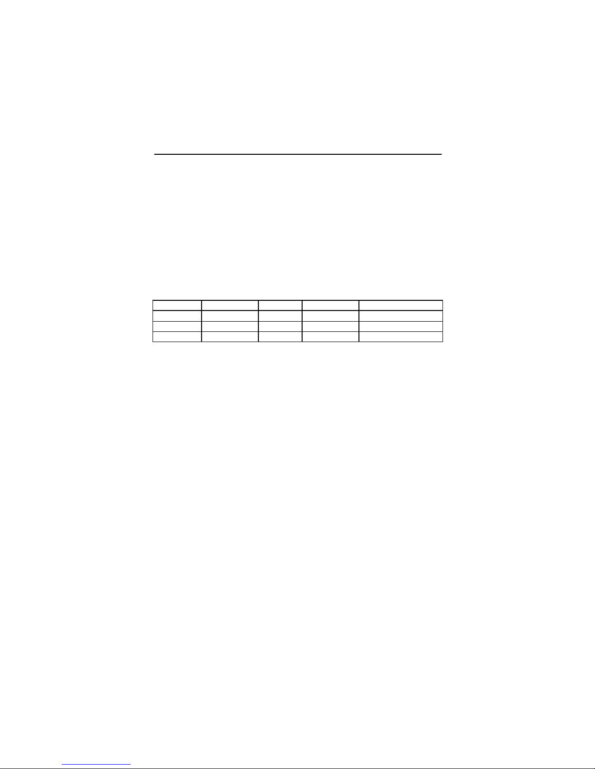
REVISION
CHANGES
DATE
NUMBER
A
Initial Release
03-14-05
The Tech Source logo and Tech Source GFX are trademarks of
Tech Source, Inc. X Window System is a trademark and product
of X. org.
All other products or services mentioned in this document are
identified by the trademarks or service marks of their respective
companies or organizations. Tech Source, Inc. disclaims any
responsibility for any references to those trademarks herein.
All rights reserved. No part of this work may be reproduced in
any form or by any means without prior written permission of the
copyright owner.
RESTRICTED RIGHTS LEGEND: Use, duplication, or disclosure
by the U.S. Government is subject to restrictions of FAR 52.22714(g)(2)(6/87) and FAR 52.227-19 (6/87); or DFAR 252.2277015(b)(6/95) and DFAR 227.7202 -3(a).
The product described in this manual may be protected by one
or more U.S. patents, foreign patents, and/or pending
applications.
Page 3

PREFACE
This publication documents the Tech Source, Inc. GFX
installation and reference. This manual is intended for users
who incorporate the Tech Source GFX graphics cards into their
PCI workstations. All systems vary to a degree. Knowledge of
the features of your system and an understanding of UNIX shell
scripts are helpful during the installation process.
WARRANTY
The GFX 400 Series graphics cards are warranted for one (1)
year from date of shipment. During the warranty period, Tech
Source, Inc. will, at its discretion, repair or replace a defective
product at its expense. Freight charges associated with the
repair or replacement of products under warranty are to be
shared by Tech Source, Inc. and the customer. All customers,
domestic and international, shall bear the freight charges for the
product return. Tech Source, Inc. shall bear the outbound freight
charges up to $13.00 (USD) per returned product, whether
domestic or international. Any additional freight charge shall be
the responsibility of the customer. We suggest that you contact
your dealer first with any questions you may have about the
product. Unlimited technical support (via telephone, facsimile, or
email) is provided for one (1) year from date of shipment. The
installation of any Tech Source, Inc. hardware/software product
is the sole responsibility of the customer.
Customers will be charged an hourly rate plus materials
($300.00 USD minimum) for repairs and/or maintenance
performed by Tech Source, Inc. that are not covered by a Tech
Source, Inc. warranty or maintenance contract.
DOCUMENTATION IS PROVIDED “AS IS” AND ALL
EXPRESSED OR IMPLIED CONDITIONS, REPRESENTATIONS
AND WARRANTIES, INCLUDING ANY IMPLIED WARRANTY
OF MERCHANTABILITY, FITNESS FOR A PARTICULAR
PURPOSE OR NON-INFRINGEMENT, ARE DISCLAIMED,
EXCEPT TO THE EXTENT THAT SUCH DISCLAIMERS ARE
HELD TO BE LEGALLY INVALID.
Page 4

This page intentionally left blank.
Page 5

TABLE OF CONTENTS
INTRODUCTION 1-1
1.1 Overview 1-1
1.2 Conventions 1-2
HARDWARE INSTALLATION 2-1
2.1 Install ation Instructions 2-1
2.2 Resolution Settings 2-3
SOFTWARE INSTALLATION 3-1
3.1 Overview 3-1
3.2 Requirements 3-1
3.3 Installing GFX 400 Series Driver Software 3-2
3.3.1 CD-ROM Installation 3-2
3.4 Changing Resolution and Bit-Depth on GFX 400 Card 3-4
3.4.1 Interactive Configuration 3-5
3.4.2 Non-Interactive Configuration 3-6
3.4.2.1 Examples 3-8
3.5 Dual-Screen Mode (GFX 450 only) 3-9
3.5.1 GFX 450 Console Display Configuration 3-9
3.5.2 OpenWindows (Dual Screen Mode) Configuration 3-11
3.6 Setting GFX 400 Card as the Console (Optional) 3-12
3.6.1 GFX 400 Card as the Only Framebuffer 3-12
3.6.1.1 Ultra 5 and Ultra 10 3-12
3.6.1.2 Sun Blade 1000, 1500, 2000, Ultra 30,
Ultra 60 and Ultra 80 3-13
3.6.1.3 Sun Blade 100 3-13
3.6.2 GFX 400 Card with a Secondary Framebuffer 3-14
3.6.2.1 Other PCI Framebuffers 3-15
OPENWINDOWS 4-1
4.1 Overview 4-1
4.1.1 GFX 400 Card as the Console 4-1
4.1.2 GFX 400 Card as the Secondary Framebuffer 4-1
4.1.3 Supporting Multiple GFX 400 Heads 4-2
4.2 Common Desk Environment (CDE) 4-2
i
Page 6

TABLE OF CONTENTS (cont’d)
ADVANCED FEATURES 5-1
5.1 Overview 5-1
5.2 8+24 Simultaneous Visuals 5-1
5.3 Cached Pixmaps 5-1
5.4 OpenGL Support 5-2
REMOVING GFX 400 DRIVER SOFTWARE 6-1
6.1 Overview 6-1
TECHNICAL ASSISTANCE 7-1
7.1 Who To Call For Help 7-1
7.2 Email Address 7-1
7.3 Website 7-2
CHANGING THE CONSOLE RESOLUTION A-1
A.1 Overview A-1
A.1.1 Reason for Changing the Console Resolution A-1
A.1.2 Guidelines for Changing the Console Resolution A-2
A.1.3 EDID Auto-Detect Feature A-2
A.2 Output -Device Method A-3
A.3 Video-Mode Method A-3
A.4 Video-Timing Method A-5
A.5 Troubleshooting A-7
CARD SPECIFICATIONS B-1
B.1 GFX 420 Card and Specifi cations B-1
B.2 GFX 440 Card and Specifications B-2
B.3 GFX 450 Card and Specifications B-3
B.4 GFX 400 Series Cabling B-4
B.4.1 GFX 450 B-4
B.4.2 GFX 420 and GFX 440 B-4
B.4.2.1 Digital Monitors B-4
B.4.2.2 Analog Monitors B-5
B.5 Special Adapter for Some Sun Monitors B-8
USING NVEDIT TO MODIFY NVRAM C-1
C.1 NVRAM Edit Commands C-1
ii
Page 7

Chapter 1
INTRODUCTION
1.1 Overview
Thank you for purchasing a Tech Source GFX 400 Series
product(s). The products in this series include:
• GFX 420
• GFX 440
• GFX 450
These cards are single slot PCI cards designed to enhance the
graphics capabilities of your Sun Microsystems desktops and
servers such as the Sun Blades, Ultra Sun Fire and Enterprise
servers, while providing multi-head capability (up to 4 heads). All
products in the GFX 400 Series line are capable of supporting
resolutions of up to 1920x1200 analog and up to 1280x1024
digital (DVI). The cards can also simultaneously support 8 and
24-bit visuals.
The features and product differentiation between individual
models are summarized in the table below:
GFX 420 GFX 440 GFX 450
Number of
Heads (Max)
Video Output 2 analog or 2
Framebuffer
Size
These products support Sun's Solaris operating system (version
2.5.1 and higher). All systems vary to a degree, therefore
knowledge of the features of your system and an understanding
of UNIX shell scripts are helpful during the installation process.
2 4 2
4 analog or 4
DVI
64MB
(32MB/head)
1-1
DVI
128MB
(32MB/head)
1 analog + 1
DVI or 2
analog
32MB
(shared)
Page 8

From this point forward, all GFX 400 series products will
collectively be referred to as GFX 400, except when describing
individual models. Also, Tech Source, Inc. may be referred to as
Tech Source or TSI.
GFX 400 Series Installation and Reference Manual
1.2 Conventions
This manual will follow certain conventions throughout.
Whenever a variable name, command name, directory, or
filename is used in a paragraph, they will appear in a mono-
spaced font.
At times the reader will be instructed to enter commands at a
prompt. In this case a transcript of a sample session will be
provided where a prompt will be followed by the commands the
reader is to enter. The entire transcript will be in a mono-
spaced font with the prompt in a normal weight and the user's
entries in bold.
The prompt used in a transcript varies depending on the
circumstances. The following are some common prompts and
when they are used:
prompt# used when the user is required to have root
privileges
prompt% used when the user is not required to have root
privileges
ok prompt displayed when the user is in Boot PROM
mode
1-2
Page 9

Chapter 2
HARDWARE INSTALLATION
2.1 Installation Instructions
The GFX 400 graphics card installation is simple and consists of
a few easy steps. These installation instructions presume that
you are familiar with the Solaris operating system.
NOTE: Remember which cables go to which connectors. You
may want to label the cables and connectors before
disconnecting them.
Step 1: Turn your computer OFF, remove the
computer’s cover, find an available PCI Local
Bus slot, and remove the bracket and screw.
Ground yourself by touching the metal part on
the case.
Step 2: Install the GFX 400 card firmly into the PCI
Local Bus slot. Take care to press it evenly and
snugly into the slot. Once you are certain that
the card is installed properly into the slot, secure
Step 3: Secure the computer’s cover, attach any
it with the bracket screw.
previously removed cables, and connect the
video cable to your monitor.
The GFX 400 card supports analog or digital
displays. See Section B.4 for a description of
the parts and adapters that are available.
2-1
Page 10

GFX 400 Series Installation and Reference Manual
Each port on the GFX 420 and GFX 440 cards
supports two displays with a custom splitter
cable attached to the port. (Please refer to
Appendix B for more information on the cables.)
These cards support both analog and digital
displays. It is a matter of choosing the right dual
monitor adapter (splitter cable). Two versions of
this splitter cable are available. One provides
two standard analog VGA (DB-15) ports; this
cable is bundled with the card. For digital
displays, a cable with dual DVI ports is available.
This cable can be purchased directly from Tech
Source, Inc.
The GFX 450 has one DVI-I and one HD-15
connector. The DVI-I connector supports both
analog and DVI output. Therefore, connect the
appropriate cable depending on your monitor
type. The HD-15 supports analog video only.
Either head can be configured as console see
section 3.5.1.
Please note that some Sun monitors may
require a DB-15 to 13W3 adapter (Refer to
Appendix B, Section B.5).
Step 4: Turn ON the monitor before turning ON the
computer so that the GFX 400 card can autodetect the proper resolution for your monitor.
NOTE: If the system is currently using a secondary graphics
device, read section 3.6 on configuring the console device. The
console device is the screen on which the boot up messages
appear. A monitor must be connected to the console device
before you proceed to Chapter 3 Software Installation.
The GFX 400 card is now installed and ready for software
installation. Refer to Cha pter 3 for installing the GFX 400 Series
Driver Software.
2-2
Page 11
Chapter 2 – Hardware Installation
2.2 Resolution Settings
For monitors that support the DDC2B/EDID (Display Data
Channel) protocol, the GFX 400 card will automatically select a
compatible resolution. To override this selection, or to change
the default resolution for monitors that do not provide DDC
information, refer to Section 3.4 and Appendix A.
The default resolution for the GFX 400 card is listed in the table
below.
Board Resolution Refresh Bits/Pixels Sync
GFX 420 Auto Detect
GFX 440 Auto Detect
GFX 450 Auto Detect
- 8
- 8
- 8
If the monitor does not support the DDC2B/EDID protocol (autodetect), and the console resolution is not set using methods
described in Appendix A, the resolution will default to
1152x900@66Hz.
separate/composite
separate/composite
separate/composite
2-3
Page 12

GFX 400 Series Installation and Reference Manual
This page intentionally left blank.
2-4
Page 13

Chapter 3
SOFTWARE INSTALLATION
3.1 Overview
This chapter describes the software installation method for the
“GFX 400 Series Driver Software”.
NOTE: Please note that this software must be installed on your
system prior to running X Windows on these cards.
The software is provided on CD-ROM or by FTP and is
composed of the following packages:
• TSImko 32-bit System Software/Device
Driver
• TSImkox 64-bit System Software/Device
Driver (Solaris 7 & above only)
• TSImkow OpenWindows System Support
Software
• TSImkomn Manual pages
3.2 Requirements
The software currently supports the following Sun PCI based
systems:
• Sun Blade 100
• Sun Blade 150
• Sun Blade 1000
• Sun Blade 1500
• Sun Blade 2000
• Sun Blade 2500
• Sun Fire v220
• Sun Fire v240
• Ultra 5
3-1
Page 14
GFX 400 Series Installation and Reference Manual
• Ultra 10
• Ultra 30
• Ultra 60
• Ultra 80
• Ultra AX
• Ultra Axi
• Enterprise 250
• Enterprise 450
• Enterprise 2500
• Enterprise 3000
NOTE: If your Sun PCI system is not listed here, please contact
Tech Source, Inc.
The following are prerequisites for installing the “GFX 400 Series
Driver Software”:
• The system is running Solaris 2.5.1 or higher.
• OpenWindows Version 3.5 or higher has already been
installed on the system.
• At least 2MB of disk space is available in "/usr" and “/.”
• One or more GFX 400 cards are presently installed in the
desktop/server.
NOTE: All device drivers are loadable. No kernel changes are
required.
3.3 Installing GFX 400 Series Driver
Software
This section describes software installation from a CD -ROM.
3.3.1 CD-ROM Installation
The following are step -by-step instructions for installing the “GFX
400 Series Driver Software” from a CD -ROM.
1. Install a GFX 400 card in the computer as described in
Chapter 2.
3-2
Page 15

Chapter 3 – Software Installation
2. Boot the computer with the "-r" (reconfiguration) option.
To do this on a typical SPARC desktop/server, per form
the following steps:
• Power ON the computer.
• Wait until you see boot messages displaying on the
screen, then press and hold the Stop (L1) key, and
then press the "A" key.
• At the "ok" prompt, type "boot –r" followed by the
<Enter> key .
3. After the system has booted, log in as root.
4. Insert the CD-ROM labeled "GFX 400 Series Driver
Software-Solaris Edition" into the CD-ROM drive.
5. If /cdrom/cdrom0 exists, type:
prompt# cd /cdrom/cdrom0
Skip to step 6. Otherwise, mount the CD-ROM by typing
the following:
prompt# mount -F hsfs -O -o ro \
/dev/dsk/c0t6d0s0 /cdrom
prompt# cd /cdrom
6. The CD-ROM contains an install_all script. To
install the software, type:
prompt# ./install_all
This script will ask you a number of yes -or-no questions
(generated by Sun's pkgadd install script). Answer
these questions appropriately.
7. Reboot the system to complete the installation.
3-3
Page 16
GFX 400 Series Installation and Reference Manual
NOTE: Upon reboot, new device names will be created in the
/dev/fbs directory, one for each head.
The GFX 400 device names have a prefix mko#, where #
represents the instance number assigned by the operating
system. For the GFX 450 product, a single device name is
created. For instance, it may be called mko0. The GFX 420
presents itself has two separate devices to the operating system.
Therefore, two device names will be created for the GFX 420, for
example, mko0 and mko1. With the Quad -head GFX 440, four
device names will be created, one for each of the four heads
(displays).
NOTE: During boot-up, all GFX 400 cards may present
themselves as instances of GFX 450. That is by design.
3.4 Changing Resolution and Bit-Depth on
GFX 400 Card
The default resolution and bit-depth is either dictated by EDID
information from the connected monitor or by the console
resolution that is set (as described in Appendix A). In the
absence of either of the above, the default resolution is
1152x900@66Hz and the default bit-depth is 8-bit.
However, if you should decide to have a different resolution and
bit-depth configuration under X Windows, follow the instructions
in this section to set your resolution and bit -depth appropriately.
The mkoconfig utility can be used any time after installation to
change these parameters and to turn on dual screen mode.
NOTE: Dual Screen Mode is available only on the GFX 450
card and is described in Section 3.5 of this manual. In this
mode, the GFX 450 can only be configured to a bit depth of 24bits.
3-4
Page 17

Chapter 3 – Software Installation
Please see the man page on mkoconfig for a detailed
description.
The next two sections describe two methods of using
mkoconfig to configure the GFX 400 card.
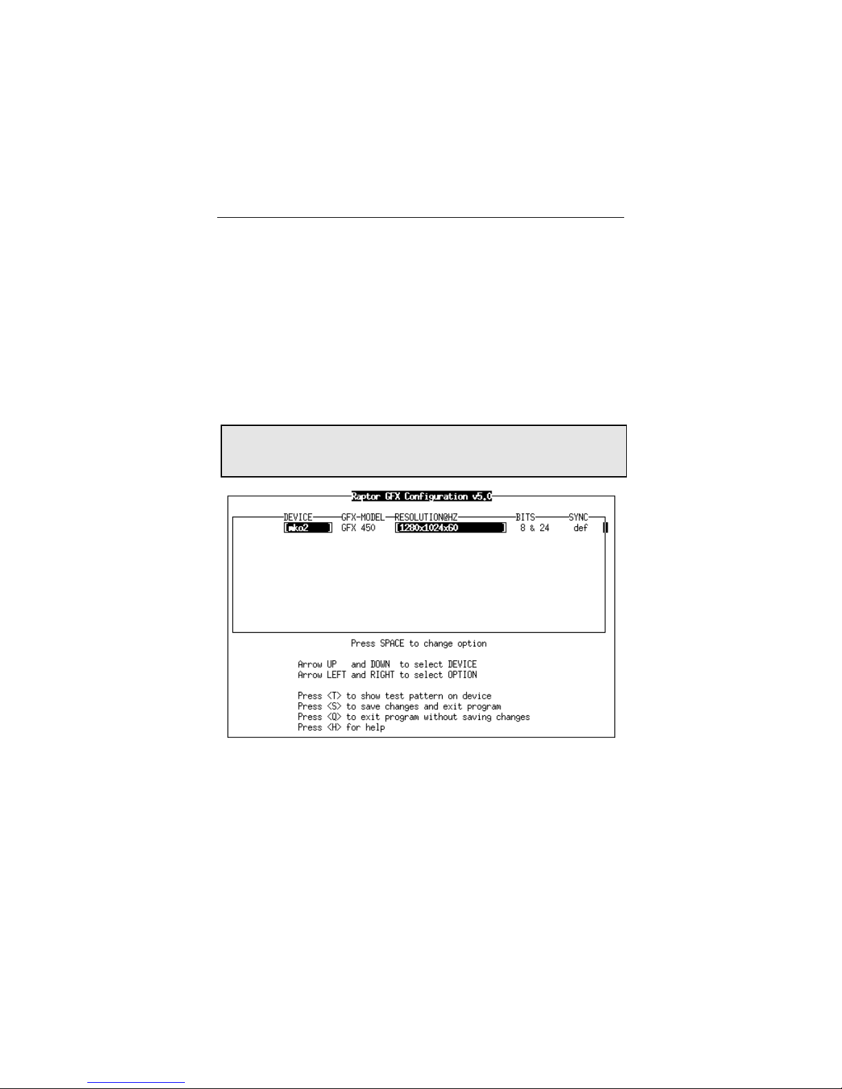
3.4.1 Interactive Configuration
mkoconfig has an interactive menu -style interface (See Figure
3.1). To use this program to configure your GFX 400 card, type:
prompt# mkoconfig -i
NOTE: If X Windows is running on the GFX 400 card(s) to be
configured, please exit out of it before running mkoconfig.
Failure to do so could result in a corrupted screen for the
remainder of the X Window session.
The GFX 400 device(s) will be listed in the left column of the
configuration screen displayed by mkoconfig. (See Figure
3.1).
A description of the commands is as follows:
Up/Down Arrow selects the desired graphics
device to modify
Left/Right Arrow selects the parameter to modify
(e.g. resolution, bit-depth, or
sync)
Space Bar modifies the parameter for the
selected graphics device (will
bring up a menu when
applicable)
3-5
Page 18
GFX 400 Series Installation and Reference Manual
‘t’ puts a test pattern on the entire
display (hit any key to return to
the main screen)
‘s’ saves current settings and exits
‘h’ help
‘q’ exits the program without saving
any changes
NOTE: To enable the dual screen feature (GFX 450 only),
select the “sync” menu and enter “w”. Please see Section
3.5 for a description of this feature.
3.4.2 Non-Interactive Configuration
Sometimes it is convenient to configure the GFX 400 card noninteractively. This method is especially useful when configuring
many systems identically or when the appropriate configuration
for the system is already known.
Figure 3.1 - GFX 400 Configuration Utility
3-6
Page 19

Chapter 3 – Software Installation
mkoconfig uses the same conventions as Sun’s m64config
or ffbconfig utilities. All of the parameters, which are set
using the interactive version, can be set by specifying the option
followed by a desired value. The parameters are:
-dev <device> selects the device to
configure
-res <resolution> sets the resolution
-res \? shows resolutions
-file machine | system specifies whether to
modify OWconfig from
/etc/openwin/
server/etc or
/usr/openwin/
server/etc
respectively
-depth 8|24 changes the bit depth to
8 only or 8+24 mode
-defaults resets device to default
parameters
-doublewidth TRUE|FALSE Enable/Disable the dual
screen output feature.
Please refer to Section
3.5.
-24only TRUE|FALSE forces all windows to
use 24 -bit visuals. This
will disable 8+24 mode
and may prohibit some
8-bit applications from
working
3-7
Page 20

GFX 400 Series Installation and Reference Manual
-cachedpixmap TRUE|FALSE Turn off the off-screen
cached pixmap feature.
Default is TRUE.
-propt displays current settings
-prconf displays hardware
information
-help shows complete usage
listing
NOTE: By default, the bit depth will be set to 8+24 for all
resolutions.
3.4.2.1 Examples
To configure the resolution on the GFX 400 card to
1152x900@66Hz, type the following:
prompt# mkoconfig -res 1152x900x66
NOTE: If no device is specified, mkoconfig configures the
console (assuming that the console is a GFX 400 card).
To verify the resolution prior to setting it permanently, add the
word "try" after the resolution name. This option will display a
test pattern on the screen until a return key is hit. Then the
resolution can be accepted or rejected. For example:
prompt# mkoconfig -dev /dev/fbs/mko0 \
–res 1152x900x66 try
3-8
Page 21

Chapter 3 – Software Installation
To set the resolution to 1024x768x60 with a single TrueColor
visual (no 8-bit PseudoColor visual):
prompt# mkoconfig -res 1024x768x60 \
-24only TRUE
To display the current settings for /dev/fbs/mko0:
prompt# mkoconfig -dev /dev/fbs/mko0 -propt
3.5 Dual-Screen Mode (GFX 450 only)
The GFX 450 has the ability to support two displays - either two
analog displays or one analog and the other DVI (digital). In
either case, the card can be configured so that the two displays
appear as one unified screen to the X Window display. In other
words, windows can be easily moved between the two displays
(without the need for a special "xinerama" mode). This
"unified screen" mode is also called the “Dual Screen”
mode. This is in contrast to what is available on the GFX 420
and GFX 440, where each head serves as an independent X
Window screen and windows cannot be moved between screens
unless the X Server is started up with "Xinerama" enabled.
For the GFX 420 and GFX 440, each of the heads is driven by
an individual graphics processor (GPU) and DAC. However, the
GFX 450 card has only one graphic processor and two DACs.
The drawing engine is capable of driving both DACs . See section
3.5.2 for more details.
3.5.1 GFX 450 Console Display Configuration
In console mode (i.e. prior to starting X Windows ), only one head
will be used. The firmware will determine which head to use
according to the following rules:
3-9
Page 22

GFX 400 Series Installation and Reference Manual
DDC From
Monitor 0
(DVI Port)
DDC From
Monitor 1
(VGA Port)
Output Resolution
Present Present Monitor 0 DDC from Monitor 0
Present Absent Monitor 0 DDC from Monitor 0
Absent Present Monitor 1 DDC from Monitor 1
Absent Absent Monitor 0 1152x900@66
Note: When the console resolution is changed using the
methods outlined in Appendix A, the output will default to Monitor
0 unless the “tsi-default-head” variable is set as described
below:
This behavior can be overridden by the tsi-default-head
variable as in the following nvramrc setting.
For example, to set the default console to Monitor 1:
ok nvedit
0: 1 value tsi-default-head
1: <ctrl-c>
ok nvstore
ok setenv use-nvramrc? true
ok reset-all
NOTE: Head 0 is the DVI connector and head 1 is the DB15
connector.
If the GFX 450 is not the console device, the driver will still use
the same rule described above to determine which head should
be the default head.
To override this behavior, you can set the “tsi-default-
head” variable in the mko.conf file under
/platform/sun4u/kernel/drv.
3-10
Page 23

Chapter 3 – Software Installation
For example, to set the default head to Monitor 1 on non-console
devices, add the following to the mko.conf file:
tsi-default-head=1;
When X Server is started in single-screen mode on a non-
console device, the default head will be used for output.
NOTE: The tsi-default-head setting in the nvramrc will
only affect the console device and the tsi-default-head
setting in mko.conf will affect only non-console GFX 450
devices. The system MUST be rebooted for the changes to take
effect.
3.5.2 OpenWindows (Dual -Screen Mode)
Configuration
Again, note that this applies to GFX 450 cards only. This card
can be configured under OpenWindows (X Windows) in either a
single screen mode or a dual screen mode, using the mkoconfig
utility. Section 3.4 discusses the mkoconfig utility.
To configure the GFX 450 card to dual screen mode, simply
specify "doublewidth [TRUE:FALSE]" on the command line as
described in section 3.4.2.
prompt# /usr/sbin/mkoconfig –dev /dev/fbs/mko0 \
-doublewidth TRUE
When running mkoconfig in the interactive mode (mkoconfig
–i), select “w” under the “sync” menu to enable dual-screen
mode.
In dual -head configurations, OpenWindows will act as one single
display across two screens. Both heads will be set to the same
resolution and each is limited to 1600x1200@60. So, the
maximum effective resolution across both screens is
3-11
Page 24

GFX 400 Series Installation and Reference Manual
3200x1200@60. In this dual-head mode, only the 24-bit
TrueColor visual is supported.
In single-head configurations, the resolution is limited to
1920x1200@76, and supports 8-bit, 24-bit, and 8+24-bit modes.
NOTE: These limits apply to analog output only. Digital output
is restricted to 1280x1024@60. Dual-head configurations that
include a digital monitor will likewise be limited to
1280x1024@60 for both heads.
3.6 Setting GFX 400 Card as the Console
(Optional)
This section describes how to configure the GFX 400 card to be
the console device for your system.
NOTE: If the procedure for your system is not described below,
please contact Tech Source, Inc.
3.6.1 GFX 400 Card as the Only Framebuffer
3.6.1.1 Ultra 5 and Ultra 10
The GFX 400 card can be configured to be the console device.
To do so, disable the on -board card on the Ultra 5 or 10. At the
"ok" prompt, type:
ok setenv pcib-probe-list 1,3
ok reset
Once the system is reset, all console messages will be directed
to the GFX 400 card.
NOTE: To restore the motherboard’s 8-bit graphics device as
the console for any reason, simply add it back to the
pcib-probe-list as below:
ok setenv pcib-probe-list 1,2,3
ok reset
3-12
Page 25

Chapter 3 – Software Installation
3.6.1.2 Sun Blade 1000, 1500, 2000, Ultra 30, Ultra 60, Ultra
80 and other systems without any built-in frame buffers
If no other framebuffers are present in a Sun Blade 1000 or
another supported system, then the GFX 400 will be the console
by default, provided that the board is in a valid, probed PCI slot.
3.6.1.3 Sun Blade 100
By default, the onboard video card is the last item in the pciprobe-list. After being properly installed in the system, if the
GFX 400 card is the only other graphics card in the system, it will
be probed first, and will automatically be made the console.
However, any graphics card or head can be made the console.
Follow the procedure below to set the console manually.
1. At the ok prompt, type the following to display a list of the
installed graphics devices:
ok show-displays
a) /pci@1f,0/SUNW,m64B@13
b) /pci@1f,0/pci@5/SUNW,Expert3D-Lite@1
c) /pci@1f,0/pci@5/pci@1/TSI,mko@c
d) /pci@1f,0/pci@5/pci@1/TSI,mko@8
e) /pci@1f,0/pci@5/pci@1/TSI,mko@4
f) /pci@1f,0/pci@5/pci@1/TSI,mko@0
q) NO SELECTION
Enter Selection, q to quit:
2. Type a letter at the prompt to select the graphics card you
want to be the default console display.
In this example, type a to select the onboard M64 graphics
device.
3-13
Page 26

GFX 400 Series Installation and Reference Manual
Enter Selection, q to quit: a
/pci@1f,0/SUNW,m64B@13 has been selected
Type ^Y ( Control-Y ) to insert it in the
command line.
e.g. ok nvalias mydev ^Y
3. Set the selected device as the console device by typing:
ok setenv output-device <Control-Y>
4. Power off the system.
5. Connect your monitor cable to the onboard VGA connector
on your system back panel.
6. Power on the system.
3.6.2 GFX 400 Card with a Secondary Framebuffer
The GFX 400 card can be made the console device when other
secondary framebuffers are present in the system.
To configure the GFX 400 card as the console when UPA based
device or other framebuffers are in the system, the output-
device variable in NVRAM must be changed to the actual path
of the desired GFX 400 card. This path can best be determined
by searching for the string "TSI" in the / tree at the "ok" prompt.
For example, to find the PCI devices, at the "ok" prompt, type
the following:
ok show-devs
You should see at least one entry containing the string "TSI", ie.
"TSI,mko@#", where ‘#’ will be a digit representing the PCI slot
containing the GFX 400 card.
3-14
Page 27
Chapter 3 – Software Installation
Use this entry as the console device for your desired GFX 400
card.
For example, if the path to the device "TSI,mko@#" is
"/pci@1f,4000", then type the following command:
NOTE: Replace ‘#’ with whatever your GFX 400 device
requires.
ok setenv output-device /pci@1f,4000/TSI,mko@#
ok reset
Once the system is reset, all console messages will be directed
to the GFX 400 card.
NOTE: To restore the default graphics device as the console for
any reason, simply set the output-device variable back to its
default value of screen as below:
ok setenv output-device screen
ok reset-all
3.6.2.1 Other PCI Framebuffers
To make the GFX 400 card the console device when other PCI
framebuffers are present in the system, it may be necessary to
change the pcia-probe-list to probe the GFX 400 slot
before that of the secondary framebuffer (in addition to making
the changes in 3.6.1.1, if applicable).
Determine the slot numbers that correspond to these
framebuffers, then ensure that the GFX 400 device slot number
precedes that of the secondary framebuffer in the pcia-probe-
list.
3-15
Page 28

GFX 400 Series Installation and Reference Manual
For example, if the GFX 400 device is located in slot 3, and the
secondary framebuffer is located in slot 1, then update the
pcia-probe-list so that slot 3 is probed BEFORE slot 1.
A possible configuration may resemble the following:
ok setenv pcia-probe-list 3,2,1,4
ok reset-all
Once the system is reset, all console messages will be directed
to the GFX 400 card.
3-16
Page 29
Chapter 4
OPENWINDOWS
4.1 Overview
This section describes how to start up OpenWindows on a GFX
400 card. The GFX 400 device name will be mko#, where ‘#’
represents the device instance number. GFX 420 and GFX 440
cards can have multiple device names – one for each head. A
GFX 450 card however, will have a single device name
corresponding to both heads.
To set the resolution and bit-depth for OpenWindows, please use
the mkoconfig utility as described in Section 3.4.
4.1.1 GFX 400 Card as the Console
If the GFX 400 device is the console, type:
prompt# openwin
4.1.2 GFX 400 Card as the Secondary Framebuffer
If the PGX card is the console and the GFX 400 device is the
second card, to start OpenWindows on both cards, in
multiscreen mode, type:
prompt# openwin -dev /dev/fbs/m640 \
-dev /dev/fbs/mko0
The order of the devices corresponds to the order of the screens.
NOTE: In the above example the mko device number is 0. This
may be different in your configuration. Please check in
/dev/fbs/ or dmesg for the correct device numbers.
4-1
Page 30

GFX 400 Series Installation and Reference Manual
4.1.3 Supporting Multiple GFX 400 Heads
GFX 420 and GFX 440 support multiple heads per card,
OpenWindows can be started on each head in a multi-screen
configuration. For example, a GFX 440 with four devices
named, mko0, mko1, mko2 and mko3, the command to invoke
OpenWindows on all four screens is:
prompt# openwin -dev /dev/fbs/mko0 -dev
/dev/fbs/mko1 -dev /dev/fbs/mko2 dev
/dev/fbs/mko3
Note: The order of the screens can be changed by just
rearranging the order in which the devices are specified on the
command line.
4.2 Common Desktop Environment (CDE)
If you have installed CDE and would like CDE to appear on the
GFX 400 display, you may need to modify your
/etc/dt/config/Xservers file.
If the file /etc/dt/config/Xservers does not exist, please
copy it from the /usr/dt/config directory. Type:
prompt# cp /usr/dt/config/Xservers \
/etc/dt/config
If the directory does not exist, type:
prompt# mkdir /etc/dt/config
prompt# cp /usr/dt/config/Xservers \
/etc/dt/config
4-2
Page 31

Chapter 4 – Openwindows
NOTE:
If the name of your GFX 400 device is something
If the GFX 400 card is the console device, then there is no need
to modify the Xservers file.
The sample Xservers.mko file which is provided, assumes
that the GFX 400 card is the only framebuffer on which to start
CDE:
:0 Local local_uid@console root \
/usr/openwin/bin/Xsun :0 –dev \
/dev/fbs/mko0 –nobanner
other than mko0, please substitute the correct name in the file.
You may add any other desired command line arguments to the
end of this line. For example, you may start CDE on multiple
displays. To do this, list each display device following the
convention above.
The following configuration displays CDE on the display named
/dev/fbs/mko0 and uses the device named /dev/fbs/m640
(the built in graphics device on Sun Ultra 5/10 systems) as a
secondary framebuffer:
:0 Local local_uid@console root \
/usr/openwin/bin/Xsun :0 –dev /dev/fbs/mko0 \
-dev /dev/fbs/m640 –nobanner
4-3
Page 32

GFX 400 Series Installation and Reference Manual
This page intentionally left blank.
4-4
Page 33

Chapter 5
ADVANCED FEATURES
5.1 Overview
The GFX 400 card has several advanced features available
through the X Server. They are:
• 8+24-bit simultaneous visuals
• Off-screen pixmap caching
• OpenGL support via Sun’s DPA extension
5.2 8+24 Simultaneous Visuals
The 8+24 mode simultaneously supports 8 and 24-bit visuals.
This addresses the classic colormap flashing issue with a 24-bit
visual while providing the 8-bit visual that is required by some
legacy applications, such as SoftWindows.
The available visuals are PseudoColor and TrueColor.
PseudoColor is the default visual.
5.3 Cached Pixmaps
All GFX 400 Series cards support off-screen pixmap caching.
Cached pixmaps are those that are stored in the off-screen
memory. These off-screen pixmaps allow faster transfer rates to
and from on -screen windows.
The available off-screen memory depends on the amount of
video memory, the current resolution, and depth settings. For
example, consider the GFX 450 card, which has 32MB of video
memory.
5-1
Page 34

GFX 400 Series Installation and Reference Manual
If it is run ning at 1024x768 resolution with a depth of 8-bits, 768K
is used for on-screen memory. That leaves 31.2MB available for
pixmaps. In 24-bit and 8+24-bit modes, the on -screen memory
that is used is 4 times larger than what is used in the 8-bit mode.
The largest pixmaps are stored in off-screen memory. If a larger
pixmap replaces a smaller pixmap in the off-screen memory, the
smaller pixmap will move to system memory and remain there
even after the larger pixmap is destroyed.
5.4 OpenGL Support
OpenGL support is provided through the Direct Pixel Access
(DPA) Extension. To use this function, OpenGL v1.1.1 or higher
must already be installed on your system.
NOTE: In OpenGL v1.1.1 for Solaris, there is a bug in the DPA
PCI 24-bit support that causes the red and blue colors to be
swapped. There is a patch from Sun (Patch ID 106022-07) that
fixes this problem. It is fixed in OpenGL v1.1.2.
5-2
Page 35

Chapter 6
REMOVING GFX 400 SERIES
DRIVER SOFTWARE
6.1 Overview
To find out if any “GFX 400 Series Software” exists on your
system, type:
prompt# pkginfo | grep TSImko
If you see any response to the command, then you currently
have some “GFX 400 Seri es Driver Software” installed.
To uninstall the “GFX 400 Driver Software”, enter the following
command:
For Solaris 2.6 and Solaris 2.5.1, type:
prompt# pkgrm TSImkomn TSImkow TSImko
For Solaris 7, Solaris 8 and Solaris 9, type:
prompt# pkgrm TSImkomn TSImkow TSImko TSImkox
Warning: This uninstall procedure may not work with older
versions of the TSI software. It is important to use the procedure
provided with the previous version.
6-1
Page 36

GFX 400 Series Installation and Reference Manual
This page intentionally left blank.
6-2
Page 37

Chapter 7
NOTE:
Tech
nical Assistance will be available only for
TECHNICAL ASSISTANCE
7.1 Who to Call for Help
If you need help, please call our Technical Support Team at
(800) 330-8301, or directly at (407) 262 -7100 between the hours
of 9:30am - 5:30pm EST Monday through Friday.
Please have the software part number, version, and serial
number for your GFX card(s) available when contacting Tech
Source in order to expedite support. Please make a note of this
information in the area below:
DETAILS OF YOUR CARD(S):
P/N: _________________________________
Model Name: ___________________________
Serial Number(s): ____________________
products under standard or extended warranty.
7.2 Email Address
Our email address is hotline@techsource.com.
International customers may use email or our fax line at
(407)339-2554.
7-1
Page 38

GFX 400 Series Installation and Reference Manual
7-2
7.3 Website
Detailed product informat ion and Frequently Asked Questions
(FAQs) are available on our website located at:
http://www.techsource.com
Page 39

Appendix A
CHANGING THE CONSOLE
RESOLUTION
A.1 Overview
The GFX 400 card can be configured to be the console in a
typical SPARC desktop/server. Every GFX 400 card type has its
own default console resolution and default depth as shown in the
following table:
Board Resolution Refresh Bits/Pixels Sync
GFX 420 Auto Detect
GFX 440 Auto Detect
GFX 450 Auto Detect
It is possible to change the default resolution on all GFX 400
cards. The procedures described in this appendix are:
• EDID Auto-Detect feature
• Output Device Method
• Video-Mode Method
• Video-Timing Method
This appendix includes a troubleshooting section describing
possible problems and answers associated with changing the
console resolution.
- 8
- 8
- 8
A.1.1 Reason for Changing the Console
Resolution
Normally the default console resolution is sufficient for most
users. An example of when you might be required to change the
default resolution is described below:
Separate/composite
Separate/composite
Separate/composite
A-1
Page 40

GFX 400 Series Installation and Reference Manual
• If the monitor does not "sync up" at the default console
resolution, it may be necessary to choose a different console
resolution.
A.1.2 Guidelines for Changing the Console
Resolution
There are some general guidelines to follow when changing the
default console resolutions. They are as follows:
• By default, all console resolutions will automatically be set to
8-bit mode.
• It is recommended that you use mkoconfig –i to test a
resolution before configuring the console to that resolution.
• Digital output on the DVI port is limited to 1280x1024@60.
A.1.3 EDID Auto-Detect Feature
Auto-Detect is limited to 1280x1024@60 on the DVI port only. If
overrides are used to exceed this limit, only analog signals will
be produced by the DVI port. Digital signals will be turned off.
If you are using a monitor with DDC2B/EDID protocol the default
resolution will be determined using the Auto-Detect feature.
With this protocol, the GFX 400 card first checks the Established
Timing Identifiers (taking the first one supported) then tries to
match the Standard Timings.
NOTE: The monitor must be turned ON prior to booting the
system in order for the GFX 400 card to communicate with it.
Some adapters and cables may block this signal.
A-2
Page 41

Appendix A – Changing the Console Resolution
If the Auto-Detect feature fails the card will default to
1152x900@66Hz.
Other methods described in this appendix will override any
information obtained via EDID.
A.2 Output -Device Method
To specify the console resolution of a GFX 400 card via the
output-device environment variable, use the format
screen:rAxBxC where:
A is the desired horizontal resolution,
B is the desired vertical resolution,
C is the desired refresh rate.
The system will check these values against an internal list of
resolutions (see section A.3 for valid list) and use the
corresponding entry as the console resolution. For example, to
use VESA 1024x768x75 as the console resolution, type the
following at the ok prompt:
ok setenv output-device screen:r1024x768x75
ok reset-all
NOTE: The new console resolution will take effect following the
reset, and will hold the resolution information until the output-
device variable is changed manually.
A.3 Video- Mode Method
At the "ok" prompt in Boot PROM mode, the console resolution
can be easily set on GFX 400 cards by using one of the 40
preinstalled resolution modes. These resolution settings are
identified by video modes 1-40.
A-3
Page 42

GFX 400 Series Installation and Reference Manual
NOTE: The default console of all video modes is 8 bits.
1 640x480@72
2 640x480@75
3 640x480@85
4 800x600@60
5 800x600@72
6 800x600@75
7 800x600@85
8 1024x768@60
9 1024x768@70
10 1024x768@75
11 1024x768@77 *
12 1024x768@85
13 1024x800@85 *
14 1152x900@60
15 1152x900@66 *
16 1152x900@70
17 1152x900@75
18 1152x900@76 *
19 1152x900@85
20 1280x800@76 *
21 1280x1024@60
22 1280x1024@67
23 1280x1024@67 *
24 1280x1024@75
25 1280x1024@76 *
26 1280x1024@85
27 1600x1000@66 *
28 1600x1000@76 *
29 1600x1200@60
30 1600x1200@65
31 1600x1200@70
32 1600x1200@75
33 1600x1200@85
34 1600x1280@76*
A-4
Page 43
Appendix A – Changing the Console Resolution
35 1920X1080X60
36 1920X1080X72*
37 1920X1080X80
38 1920X1200@60
39 1920X1200@70
40 1920X1200@76
NOTE: The resolution followed by a * uses composite sync.
NOTE: Please refer to Appendix C for a description of nvedit
commands.
ok nvedit
0: 8 value video-mode
1: <ctrl-c>
ok nvstore
ok setenv use-nvramrc? true
ok reset-all
NOTE: The last three commands enable the NVRAM. Without
these lines, the changes you make with nvedit will be ignored.
A.4 Video- Timing Method
If all of the previously described methods fail for your
configuration, it is possible to specify the exact timing numbers
for a particular resolution. The last method for setting the
console resolution also uses nvedit. This method is more
involved and requires knowledge of all timing parameters for the
desired resolution, and is only meant for monitors whose
resolutions are not available in the video-mode method.
Please refer to Appendix C for detailed instructions on using
nvedit.
NOTE: The video-timing method should be used only if the
previous methods have been unsuccessful.
A-5
Page 44

GFX 400 Series Installation and Reference Manual
For example, to set the console resolution to 1280x1024@76Hz,
type the following:
ok nvedit
0: : video-timing " 1280, 384, 32, 64,
1024, 43, 3, 8, 135000000, 0" ;
1: <ctrl-c>
ok nvstore
ok setenv use-nvramrc? true
ok reset-all
NOTE: The syntax is very important. The spaces must be
present exactly as they appear in the example.
NOTE: The last three commands enable the NVRAM. Without
these lines, the changes you make with nvedit will be ignored.
The following is a brief description of the 10 parameters used in
this method.
• horizontal resolution (in pixels)
• horizontal blanking total
• horizontal front porch
• horizontal sync width
• vertical resolution (in lines)
• vertical blanking total
• vertical front porch
• vertical sync width
• dotclock in Hz
• sync value:
0 separate sync
256 sync on green
512 positive vertical sync pulse
1024 positive horizontal sync pulse
2048 composite sync
A-6
Page 45

Appendix A – Changing the Console Resolution
The sync values can be added together to select more than one
of the above.
NOTE: To obtain the timing parameters required to use the
video-timing method, please contact Tech Source with your
monitor's requirements.
A.5 Troubleshooting
Problem Solution
Used the
method
described in the
Appendix to
configure the
console
resolution, but
the card still
defaults to
something other
than the
resolution
specified.
A priority scheme is used to determine the
boot console resolution. The GFX 400
firmware checks the various methods in the
order of priority discussed below. If it finds
the resolution from the current method, it
uses it; otherwise, it goes down the priority
list to find the resolution information. Finally,
if there is no resolution information, it uses
the default resolution. The resolution -setting
methods are enumerated in order of
decreasing priority:
1. output-device method (Section A.2)
2. video-timing method (Section A.4)
3. video-mode method (Section A.3)
4. DDC2B/EDID (Section A.1.3)
5. Default res olution for the card
A-7
Page 46

GFX 400 Series Installation and Reference Manual
This page intentionally left blank.
A-8
Page 47

Frame Buffer:
64 Megabytes (32MB/head)
Appendix B
CARD SPECIFICATIONS
B.1 GFX 420 Card and Specifications
Hardware Cursor: 3 color, 64 x 64 bitmap
Color Lookup
Table(s): 256 entries
PCI Interface: 33 MHz, 32-bit, Ver 2.1
Video Interface Analog, (50 ohm) TMDS
(DVI)
Temperature 00 to 550 C operating
Rating: -400 to 750C non-operating
Humidity Rating 20 to 80% operating
(non-condensing)
5 to 95% non-operating
(non-condensing)
Power Rating: +5V @ 3 Amps
Dimensions: 165mm x 114mm
(6.5”x 4.5”)
Dot Clock Max: 360MHz (analog)
135MHz (digital)
Video Sync: Separate, composite
Video Connector: LFH-60 (15pm D-shell, VGA
or DVI-I using splitter cable)
Boot Support: IEEE 1275 Compliant F Code
B-1
Page 48
GFX 400 Series Installation & Reference Manual
Frame Buffer:
128 Megabytes (32MB/head)
B.2 GFX 440 Card and Specifications
Hardware Cursor: 3 color, 64 x 64 bitmap
Color Lookup
Table(s): 256 entries
PCI Interface: 33 MHz, 32-bit, Ver 2.1
Video Interface Analog, (50 ohm) TMDS
(DVI)
Temperature 00 to 550 C operating
Rating: -400 to 750C non-operating
Humidity Rating 20 to 80% operating
(non-condensing)
5 to 95% non-operating
(non-condensing)
Power Rating: +5V @ 3 Amps
Dimensions: 165mm x 114mm
(6.5”x 4.5”)
Dot Clock Max: 360MHz (analog)
135MHz (digital)
Video Sync: Separate, composite
Video Connector: LFH-60 (x2) (15pm D-shell,
VGA or DVI-I using splitter
cable)
Boot Support: IEEE 1275 Compliant F Code
B-2
Page 49

Frame Buffer:
32 Megabytes
Appendix B – Card Specifications
B.3 GFX 450 Card and Specifications
Hardware Cursor: 3 color, 64 x 64 bitmap
Color Lookup
Table(s): 256 entries
PCI Interface: 33 MHz, 32-bit, Ver 2.1
Video Interface Analog, (50 ohm) TMDS
(DVI)
Temperature 00 to 550 C operating
Rating: -400 to 750C non-operating
Humidity Rating 20 to 80% operating
(non-condensing)
5 to 95% non-operating
(non-condensing)
Power Rating: +5V @ 3 Amps
Dimensions: 149.8mm x 97mm
(5.90” x 3.8”)
Dot Clock Max: 360MHz (primary)
230MHz (secondary)
135MHz (digital)
Video Sync: Separate, composite
Video Connector: 15pm D shell VGA (x1),
DVI-I (x1)
Boot Support: IEEE 1275 Compliant F Code
B-3
Page 50

GFX 400 Series Installation & Reference Manual
B.4 GFX 400 Series Cabling
B.4.1 GFX 450
GFX 450 has one DVI-I and one HD-15 connector. The DVI-I
connector supports both analog and DVI output. Therefore,
connect the appropriate cable depending on your monitor type.
The HD-15 supports analog video only.
B.4.2 GFX 420 and GFX 440
Both of these cards have LFH60 connectors for video output and
require special splitter cables. Detailed descriptions for
connecting various monitors are provided in the sub sections
below.
Attach the GFX 400 Series dual-monitor adapters (splitter
cables) to the connectors on the bracket of your GFX 400 Series
card. Make sure the connectors are firmly in place. The other
end of each adapter has DVI connectors to plug into each of the
two displays. Please refer to illustrations in Figures B.1 and B.2.
B.4.2.1 Digital Monitors
The supplied dual-monitor adapter supports digital LCD flat
panel displays with a DVI interface. These displays must have a
DVI-D or DVI-I input connector. Refer to Figure B.1 for an
illustration. Connect the LCD’s video cable to one of the two
connectors of the dual monitor adapter.
B-4
Page 51

Appendix B – Card Specifications
Make sure the other end of each monitor cable is properly
connected to its monitor. See your monitor manuals for more
information.
Figure B.1
B.4.2.2 Analog Monitors
For analog monitors use the DVI to VGA adapter in conjunction
with the dual-monitor adapter. Analog monitors typically use HD15 connectors to connect to the graphics card. Connect the
monitor cable to one of the two connectors of the dual-monitor
adapter. Refer to Figure B.1 for an illustration of this
connection.
B-5
Page 52

GFX 400 Series Installation & Reference Manual
Make sure all connectors are firmly in place.
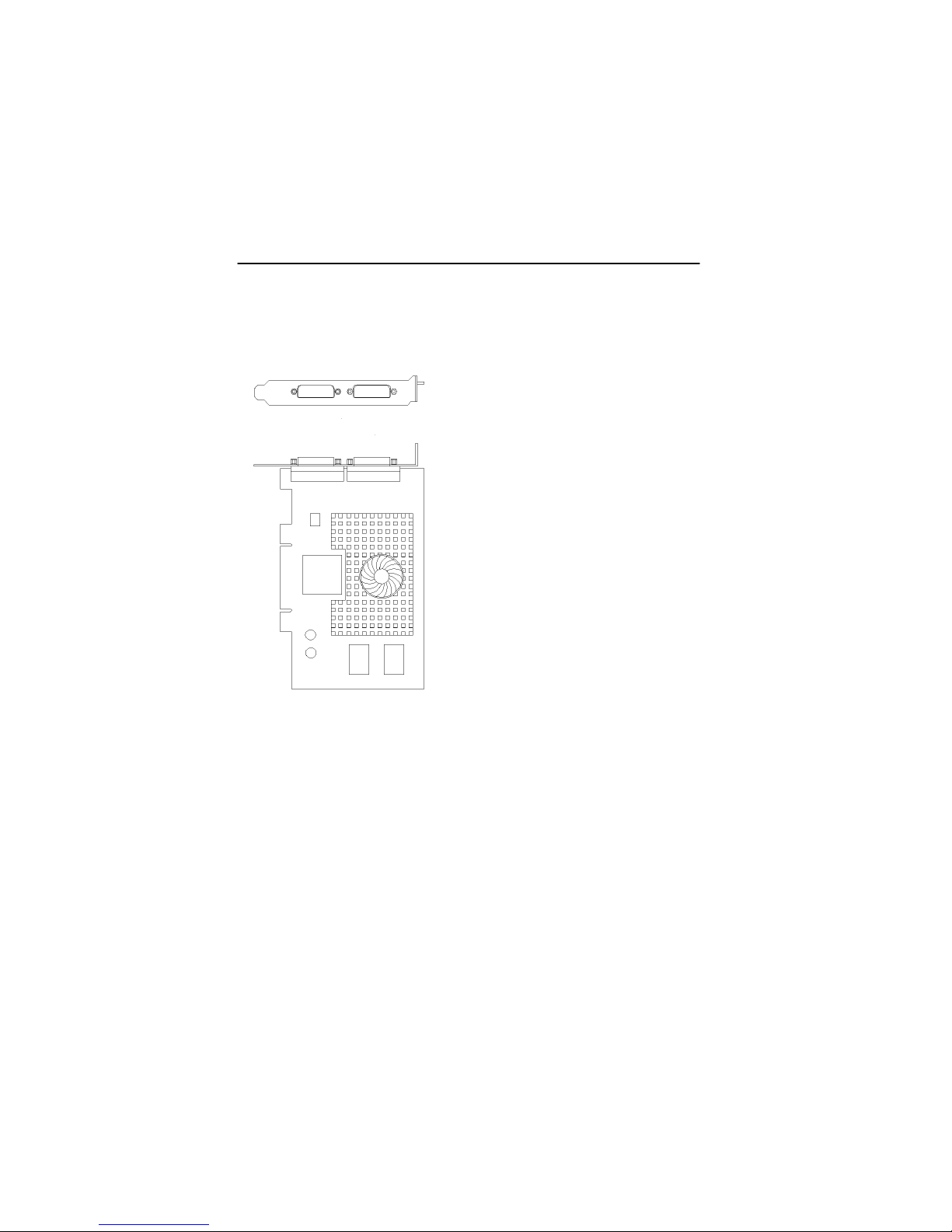
Figure B.2
NOTE: Monitors are numbered consecutively based on which
connector each is attached to (Refer to Figure B.3). Numbering
starts with the primary display – the one that first displays
information when you restart your computer. If another graphic
card is installed in your computer, display numbering may be
different.
Figure B.3
B-6
Page 53

Appendix B – Card Specifications
NOTE: Your dual-monitor adapter can only be used with DVI
based displays. DVI to VGA adapters are included for use with
analog displays.
GFX 400 Series adapters that support digital monitors use DVI-D
connectors – these adapters don’t use P&D or MDR-20
connectors.
Figure B.4
B-7
Page 54

GFX 400 Series Installation & Reference Manual
B.5 Special Adapter for Some Sun
Monitors
The GFX 400 Series have a DVI to VGA adapter for use with
analog monitors. Some Sun monitors and cables require a 13W3
to VGA adapter such as the 1396 adapter shown below. This
adapter provides composite sync on 13W3 connection.
B-8
Page 55

Appendix C
USING NVEDIT TO MODIFY
NVRAM
C.1 NVRAM Edit Commands
This section discusses the use of NVRAM. The NVRAM is used
to set the resolution in the Video-Mode and Video-Timing
methods. To edit the NVRAM, begin nvedit at the ok prompt.
There are several commands that you must use to edit the
variables in NVRAM:
<Backspace> deletes the character preceding the cursor
<Ctrl-l> lists NVRAM current values
<Ctrl-p> moves to the previous line
<Ctrl-n> moves to the next line
<Ctrl-b> moves to the previous character
<Ctrl-f> moves to the next character
<Ctrl-u> deletes to the beginning of the line
<Ctrl-k> joins the current and next line
<Ctrl-u><Ctrl-k> deletes the current line
<Ctrl-c> exits the NVRAM editor (back to the ok
prompt)
The changes will only take effect if they are stored using the
nvstore command entered at the ok prompt. Once the
changes are stored, the NVRAM must be enabled before the
system will execute it. This is done by setting the environment
variable use-nvramrc? to true. Please reset the system to
make the changes effective.
C-1
Page 56

GFX 400 Series Installation and Reference Manual
This page intentionally left blank.
C-2
Page 57

NOTES
Page 58

NOTES
Page 59

NOTES
Page 60

Publication #65-0263-01
 Loading...