

Page 1

Elite Series Tribrid - User's Manual
TRIDVR-EL16M4
Page 2

Table of Contents
1 FEATURES AND SPECIFICATIONS
1.1
Overview
1.2
Features
1.3
Specifications
2 OVERVIEW AND CONTROLS
2.1
Front Panel
2.2
Rear Panel
2.3
Connection Sample
2.4
Remote Control
2.5
Mouse Control
2.6
Virtual Keyboard & Front Panel
2.6.1 Virtual Keyboard
Page 3

v
2.6.2 Front Panel
3 INSTALLATION AND CONNECTIONS
3.1
Check Unpacked DVR
3.2
About Front Panel and Rear Panel
3.3
HDD Installation
3.4
Connecting Power Supply
3.5
Connecting Video Input and Output Devices
3.5.1 Connecting Video Input
3.5.2 Connecting Video Output
3.6
Connecting Audio Input & Output, Bidirectional Audio
3.6.1 Audio Input
3.6.2 Audio Output 218
3.7
Alarm Input and Output Connection
3.7.1 Alarm Input and Output Details
3.7.2 Alarm Input Port
3.7.3 Alarm Output Port
3.8
RS485
3.9
Other Interfaces
Page 4

vi
4 OVERVIEW OF NAVIGATION AND CONTROLS
4.1
Boot up and Shutdown
4.1.1 Boot up
4.1.2 Shutdown
4.1.3 Auto Resume after Power Failure
4.1.4 Replace Button Battery
4.2
Set/Reset Password
4.2.1 Set Password
4.2.2 Reset Password
4.3
Startup Wizard
4.4
Live Viewing
4.5
Right-Click Menu
4.5.1 Window Switch
4.5.2 Previous Screen/Next Screen
4.5.3 PTZ Control
4.5.4 Auto Focus
4.5.5 Color
4.5.6 Display
4.5.7 Face Search
4.5.8 Search
4.5.9 Record Control
4.5.10 Alarm Output
4.5.11
Remote Device
4.5.12
Video Matrix
4.5.13
Main menu
4.6
Navigation Bar
4.6.1 Main Menu
4.6.2 Output Screen
4.6.3 Previous/Next Screen
4.6.4 Tour
4.6.5 Favorites
4.6.6 Channel
4.6.7 PTZ
Page 5

vii
4.6.8 Color
4.6.9 Search
4.6.10 Alarm Status
4.6.11 Channel Info
4.6.12 Remote Device
4.6.13 Network
4.6.14 HDD Manager
4.6.15 USB Manager
4.7
USB Device Auto Pop-up
4.8
Main Menu
4.9
Operation
4.9.1 Search
4.9.2 Human Face Search
4.9.3 Backup
4.9.4 Shut Down
4.10
Information
4.10.1 System Info
4.10.2 Event
4.10.3 Network
4.10.4 Log
4.11
Setting
4.11.1 Camera
4.11.2 Network
4.11.3 Event
4.11.4
Storage
4.11.5 System
5 WEB OPERATION
5.1
Network Connection
5.2
Login
Page 6

viii
5.3
LAN Mode
5.4
Real-time Monitor
5.5
PTZ
5.6
Image/Relay-out
5.6.1 Image
5.6.2 Relay output
5.7
WAN Login
5.8
Setup
5.8.1 Camera
5.8.2 Network
5.8.3 Event
5.8.4 Storage
5.8.5 Setting
5.9
Information
5.9.1 Version
5.9.2 Log
5.9.3 Online User
5.9.4 HDD
5.10
Playback
5.10.1 Search Record
5.10.2 File List
5.10.3 Playback
5.10.4
Download
5.10.5 Load more
5.11
Face Search
5.12
Alarm
Page 7

ix
5.13
Log out
5.14
Un-install Web Control
6 PROFESSIONAL SURVEILLANCE SYSTEM
7 FAQ
APPENDIX A HDD CAPACITY CALCULATION
APPENDIX B COMPATIBLE BACKUP DEVICES
Appendix B-1 Compatible USB list
Appendix B-2 Compatible SD Card list
Appendix B-3 Compatible Portable HDD list
Appendix B-4 Compatible USB DVD List
Appendix B-5 Compatible SATA DVD List
Appendix B-6 Compatible SATA HDD List
APPENDIX C COMPATIBLE CD/DVD BURNER LIST
APPENDIX D COMPATIBLE DISPLAYER LIST
APPENDIX E COMPATIBLE SWITCHER
Page 8

x
APPENDIX F COMPATIBLE WIRELESS MOUSE LIST
APPENDIX G EARTHING
Page 9

xi
Welcome
Thank you for purchasing our HDCVI DVR!
This user’s manual is designed to be a reference tool for the installation and operation of
your system.
Here you can find information about this series standalone DVR features and functions, as
well as a detailed menu tree.
Before installation and operation please read the following safeguards and warnings
carefully!
Page 10

xii
Important Safeguards and Warnings
1.Electrical safety
All installation and operation here should conform to your local electrical safety codes.
The product must be grounded to reduce the risk of electric shock.
We assume no liability or responsibility for all the fires or electrical shock caused by
improper handling or installation.
2.Transportation security
Heavy stress, violent vibration or water splash are not allowed during transportation,
storage and installation.
3.Installation
Keep upwards. Handle with care.
Do not apply power to the DVR before completing installation.
Do not place objects on the DVR.
4.Qualified engineers needed
All the examination and repair work should be done by the qualified service engineers.
We are not liable for any problems caused by unauthorized modifications or attempted
repair.
5.Environment
The DVR should be installed in a cool, dry place away from direct sunlight, inflammable,
explosive substances and etc.
6. Accessories
Be sure to use all the accessories recommended by manufacturer.
Before installation, please open the package and check all the components are included.
Contact your local retailer ASAP if something is broken in your package.
7. Lithium battery
Improper battery use may result in fire, explosion, or personal injury!
When replace the battery, please make sure you are using the same model!
RISK OF EXPLOSION IF BATTERY IS REPLACED BY AN INCORRECT TYPE.
DISPOSE OF USED BATTERIES ACCORDING TO THE INSTRUCTIONS.
CAUTION
FOR YOUR OWN SAFETY, PLEASE CHANGE SYSTEM DEFAULT PASSWORD
AFTER YOU FIRST LOGIN!
Page 11

1
1 FEATURES AND SPECIFICATIONS
1.1 Overview
The standalone series DVR is an excellent digital monitor product designed for security
field.
It adopts embedded Linux OS to maintain reliable operation. Popular H.264 compression
algorithm and G.711 audio compression technology realize high quality, low bit stream.
Unique frame by frame play function is suitable for detailed analysis. It has various
functions such as record, playback, monitor at the same time and can guarantee audio
video synchronization. This series product has advanced technology and strong network
data transmission function.
This series device adopts embedded design to achieve high security and reliability. It can
work in the local end, and at the same time, when connecting it to the professional
surveillance software (PSS), it can connect to the security network to realize strong
network and remote monitor function.
This series product can be widely used in various areas such as banking,
telecommunication, electric power, interrogation, transportation, intelligent resident zone,
factory, warehouse, resources, and water conservancy.
1.2 Features
This series product has the following features:
Real-time surveillance
Support VGA port and HDMI port. Realize the surveillance through displayer. Support
HDMI, VGA, and TV output at the same time.
Storage function
Special data format to guarantee data security and can remove the risk of the vicious data
modification. Support digital watermark.
Compression format
Support multiple-channel audio and video. An independent hardware decodes the audio
and video signal from each channel to maintain video and audio synchronization.
Backup function
Support backup operation via USB port (such as U disk, portable HDD, burner)
Client-end user can download the file to local HDD to backup via network.
Record & playback function
Page 12

Support each channel real-time record independently, and at the same time it can support
search, forward play, network monitor, record search, download and etc.
Support various playback modes: slow play, fast play, backward play and frame by frame
play.
Support time title overlay so that you can view event accurate occurred time
Support customized zoom function during the preview.
Network operation
Support network remote real-time monitor, remote record search and remote PTZ control.
Alarm activation function
Several relay alarm outputs to realize alarm activation and on-site light control.
The alarm input port and output has the protection circuit to guarantee device safety.
Communication port
RS485 port can realize alarm input and PTZ control.
RS232 port can connect to keyboard to realize central control, and can also connect to PC
COM to upgrade system and realize maintenance, and matrix control.
Standard Ethernet port can realize network access function.
The dual-network port has the multiple-access, fault-tolerance, load-balance setup mode.
PTZ control
Support PTZ decoder via RS485.
Intelligent operation
Mouse operation function
In the menu, support copy and paste setup function
UPNP (Universal Plug and Play)
Establish mapping connection between LAN and WAN via UPNP protocol.
Slight function differences may be found due to different series.
1.3 Specifications
Page 13

Model Parameters 4 Channel 8 Channel TRIDVR-EL16M4
System Main Processor
Industrial embedded micro controller
OS
Embedded LINUX
Video
Parameters
Video Encode
Standard
H.264+/H.264
Encode
Resolution
stream: Main
2K(2560*1440)/1080P/720P/960H/D1/HD1/BCIF/CIF/QCIF
Sub stream: D1/CIF/QCIF
Video Frame Rate 2K resolution: PAL:1~15f/s;NTSC:1~15f/s
Other resolutions: PAL:1~25f/s;NTSC:1~30f/s
Video Bit Rate 32Kbps-6144Kbps,
Fo
r 720P: default setup is 2Mbps,max supports 4Mbps.
For 1080N: default setup is 4Mbps,max supports 6Mbps.
For 2K: non realtime default setup is 4Mbps,max supports 6Mbps.
Bit Stream Type
Video stream/composite stream
Dual-Stream
Support
Audio
Parameters
Encode Standard
G
.711A/G.711U/PCM
Audio Sampling
Rate
8KHz,16Bit
Audio Bit Rate
64K
bps
Video Port Analog Video
Input
port 4
-ch BNC
(HDCVI/CVBS)
port 8-ch BNC
(HDCVI/CVBS)
port 16-ch BNC
(HDCVI/CVBS)
Network V
ideo
Input
Max add 2 IP
channel
connection.
Analog
/digital channel
switch. Max 6 IP
channel
connections
Connection
bandwidth:8Mbp
s-24M
bps
Max add 4 IP
channel
connection.
Analog
/digital channel
switch. Max 12
IP channel
connections
Connection
bandwidth:16
Mbps-48Mbps
Max add 8 IP
channel
connection.
Analog
/digital channel
switch. Max 24 IP
channel
connections
Connection
bandwidth:32Mbps96Mbps
Video Output 1-channel VGA output,
1-channel HDMI output, max 4K(3840*2160)@30f
HDMI/ VGA video output at the same time (of the same video source
or different video source).
Loop Output
N/A
Matrix Output
When the HDMI and VGA are outputting different video, system
supports one matrix output.
Page 14

Audio Port Audio Input
1-channel RCA port.
Coaxial Audio
Input
N/A
Audio Output
1-channel RCA port.
Bidirectional Talk
Input
Reuse the audio input/output port
Record Record Mode
Schedule record/manual record/MD record/Alarm record/intelligent
record
Playback Mode
Instant playback, normal playback, event playback, mark playback,
smart playback
Playback Channel
4-channel 8-channel 16-channel
Backup Mode
HDD, burner, USB device, network backup
Alarm Alarm Input
N/A
Alarm Output
N/A
HDD HDD Port
2 SATA ports
One HDD Space
8T
Communication
Port
Network
1 RJ45 port, 1000Mbps Ethernet port
Communication
1 RS485 port
USB
2 USB ports(One USB2.0 port at the front panel and one USB3.0 port
at the rear panel)
Others Power
DC12V
Power
Consumption (No
HDD)
≤12W ≤13W ≤20W
Working
Temperature
-10
℃-+55℃
Working Humidity
10%~90%
Dimensions 1U case, 375mm(W)×280mm(D)×50mm
(H)
Weight (No HDD)
≤1.
60KG ≤1.60KG ≤1.75KG
Installation Mode
Desk
Model Parameters 4 Channel 8 Channel TRIDVR-EL16M4
Page 15
2 Overview and Controls
This section provides information about front panel and rear panel. When you install this
series DVR for the first time, please refer to this part first.
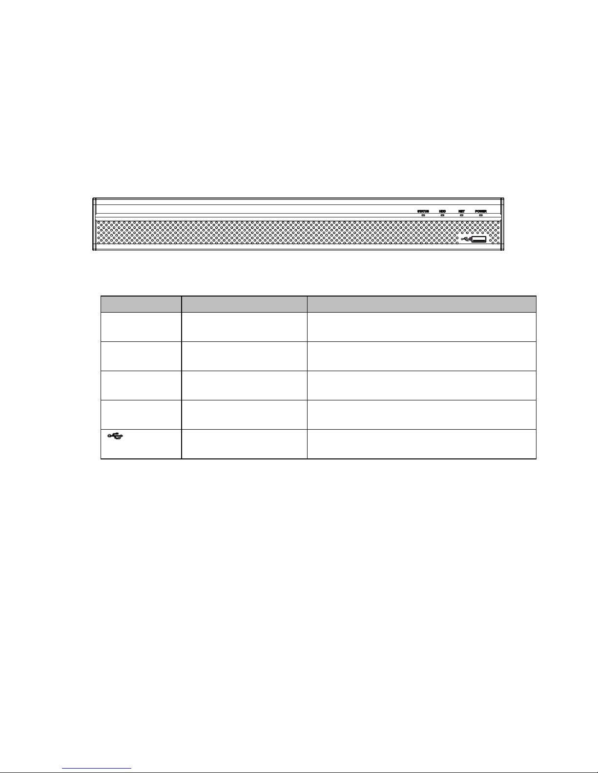
2.1 Front Panel
Figure 2-6
Please refer to the following sheet for front panel button information.
Icon Name Function
STATUS Status indicator light The blue light is on when the device is working
properly.
HDD HDD status indicator
light
The blue light is on when the HDD is malfunction.
NET Network status indicator
light
The blue light is on when the network connection is
abnormal.
POWER Power status indicator light The blue light is on when the power connection is
OK.
USB2.0 port Connect to peripheral USB 2.0 storage device,
mouse, burner and etc.
Page 16
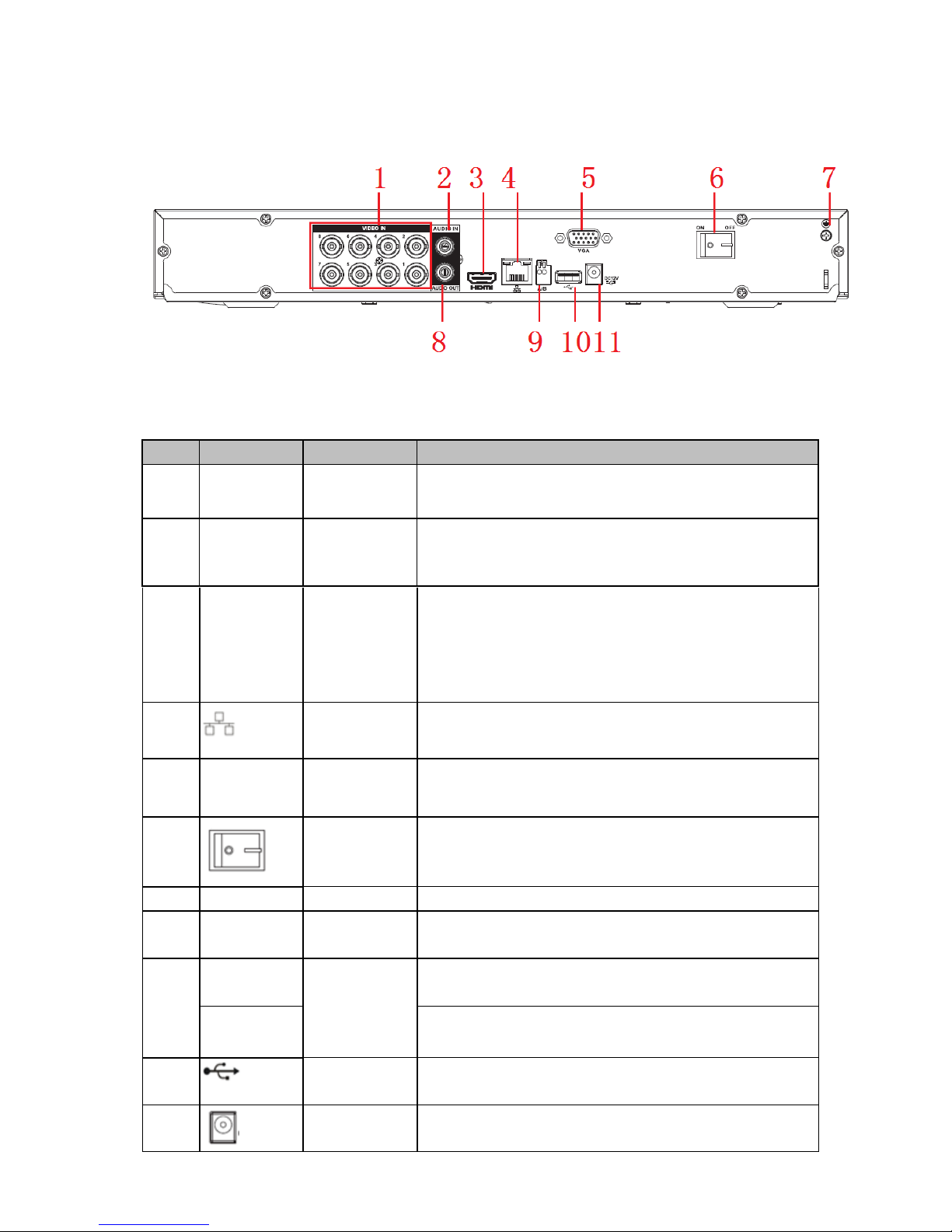
2.2 Rear Panel
3 HDMI High definition
media
interface
High definition audio and video signal output port. It
transmits the same video signal as that of the VGA/TV or
different video signal from that of the VGA/TV(support
customized setup)
.
Support mouse operation.
4 Network port 1000M Ethernet port
5 VGA VGA VGA video output port
6 Power switch Power on/off button.
7 GND Power switch Power on/off button.
8 AUDIO OUT Audio output
port
Connect to sound box and etc to output audio signal.
9 A RS485
communicatio
n port
RS485_A port. It is the cable A. You can connect to the
control devices such as speed dome PTZ.
B RS485_B.It is the cable B. You can connect to the control
devices such as speed dome PTZ.
10 USB3.0 port Connect to mouse, USB storage media, USB-burner and
etc.
11 Power socket Power input port
Figure 2-82
Please refer to the following sheet for detailed information.
SN Icon Name Function
1 VIDEO IN Video
input
port
Connect to analog camera, video input signal.
2 AUDIO IN Audio
input
port
Connect to microphone and etc to input signal.
Page 17
204
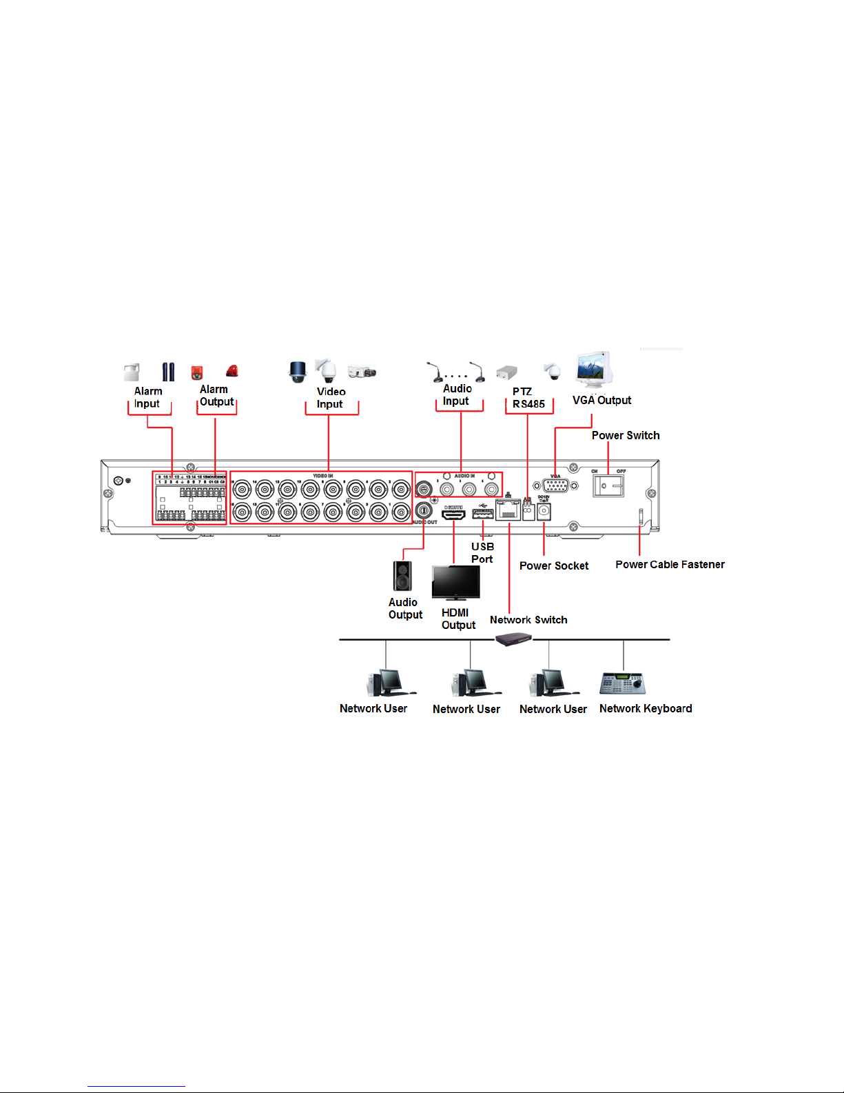
2.3.5 1U Series
Please refer to the following figure for detailed information.
2.3 Connection Sample
Page 18
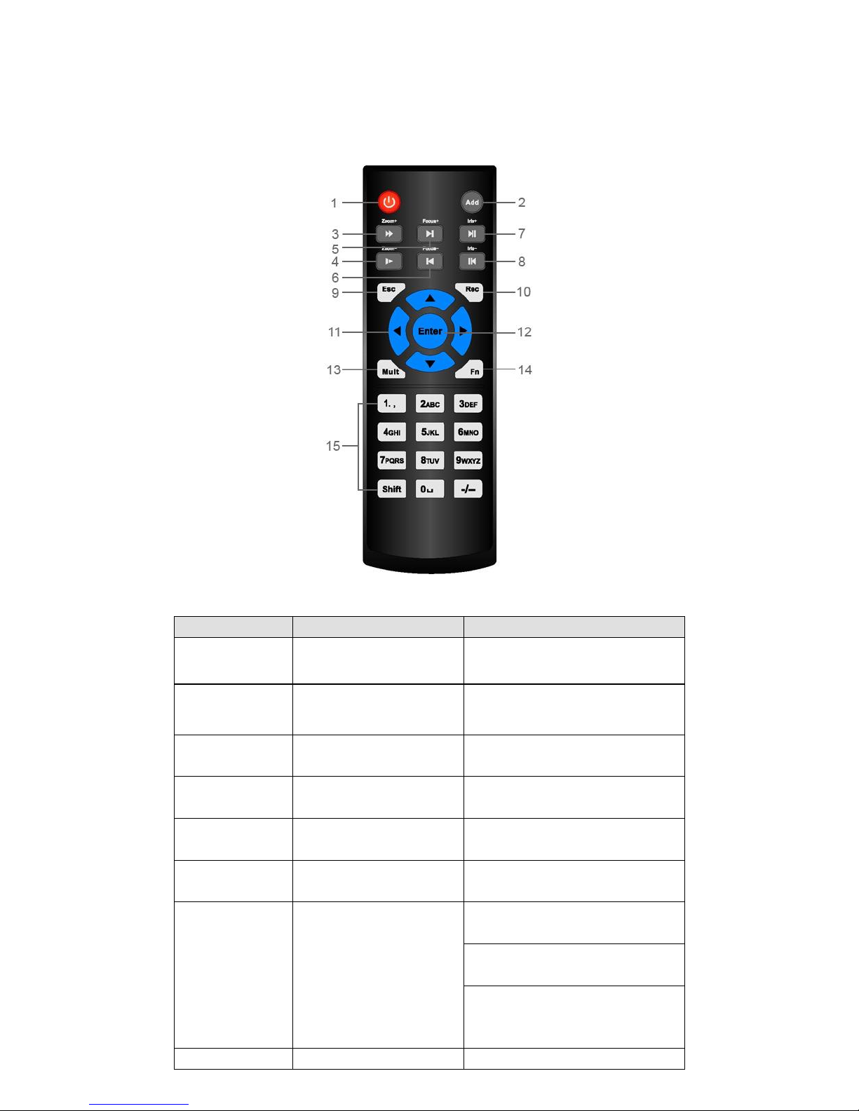
Figure 2-90
Serial Number Name Function
1 Power button Click it to boot up or shut down
the device.
2 Address Click it to input device number, so
that you can control it.
3 Forward Various forward speeds and
normal speed playback.
4 Slow play Multiple slow play speeds or
normal playback.
5
Next record In playback mode, playback the
next video.
6
Previous record In playback mode, playback the
previous video.
7 Play/Pause In pause mode, click this button
to realize normal playback.
In normal playback click this
button to pause playback.
In real-time monitor mode, click
this button to enter video search
menu.
Reverse/pause Reverse playback pause mode,
2.4 Remote Control
The remote control interface is shown as in Figure 2-90
.
Please note remote control is not our standard accessory and it is not included in the
accessory bag.
Page 19

208
8
click this button to realize normal
playback.
In reverse playback click this
button to pause playback.
9
Esc.
Go back to previous menu or
cancel current operation (close
upper interface or control)
10
Record
Start or stop record manually
In record interface, working with
the direction buttons to select the
record channel.
Click this button for at least 1.5
seconds, system can go to the
Manual Record interface.
11
Direction keys
Switch current activated control,
go to left or right.
In playback mode, it is to control
the playback process bar.
Aux function(such as switch the
PTZ menu)
12
Enter /menu key
go to default button
go to the menu
13
Multiple-window switch
Switch between multiple-window
and one-window.
14
Fn
In 1-ch monitor mode: pop up
assistant function: PTZ control
and Video color.
Switch the PTZ control menu in
PTZ control interface.
In motion detection interface,
working with direction keys to
complete setup.
In text mode, click it to delete
character.
15
0-9 number key
Input password, channel or
switch channel.
Shift is the button to switch the
input method.
2.5 Mouse Control
Left click
mouse
System pops up password input dialogue box if you have not logged in.
In real-time monitor mode, you can go to the main menu.
Page 20
209
When you have selected one menu item, left click mouse to view menu
content.
Implement the control operation.
Modify checkbox or motion detection status.
Click combo box to pop up drop down list
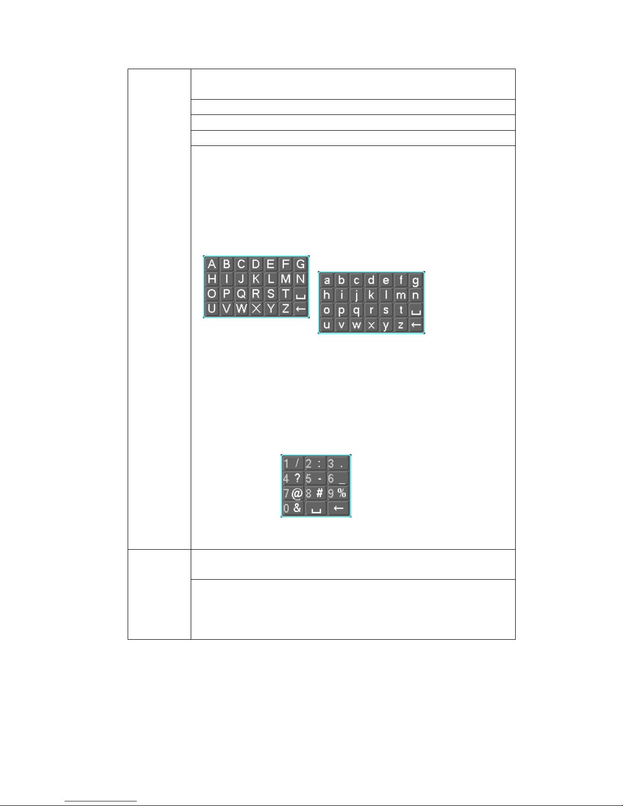
In input box, you can select input methods. Left click the corresponding
button on the panel you can input numeral/English character
(small/capitalized). Here ← stands for backspace button. _ stands for
space button.
In English input mode: _stands for input a backspace icon and ←
stands for deleting the previous character.
In numeral input mode: _ stands for clear and ← stands for
deleting the previous numeral.
When input special sign, you can click corresponding numeral in the
front panel to input. For example, click numeral 1 you can input“/” , or
you can click the numeral in the on-screen keyboard directly.
Double left
click mouse
Implement special control operation such as double click one item in
the file list to playback the video.
In multiple-window mode, double left click one channel to view in
full-window.
Double left click current video again to go back to previous
multiple-window mode.
Page 21
210
Right click
mouse
In real-time monitor mode, pops up shortcut menu: one-window,
four-window, nine-window and sixteen-window, Pan/Tilt/Zoom, color
setting, search, record, alarm input, alarm output, main menu.
Among which, Pan/Tilt/Zoom and color setting applies for current
selected channel.
If you are in multiple-window mode, system automatically switches to
the corresponding channel.
Exit current menu without saving the modification.
Press
middle
button
In numeral input box: Increase or decrease numeral value.
Switch the items in the check box.
Page up or page down
Move
mouse
Select current control or move control
Drag
mouse
Select motion detection zone
Select privacy mask zone.
2.6 Virtual Keyboard & Front Panel
2.6.1 Virtual Keyboard
The system supports two input methods: numeral input and English character (small and
capitalized) input.
Move the cursor to the text column, the text is shown as blue, input button pops up on the
right. Click that button to switch between numeral input and English input (capitalized and
small), Use > or < to shift between small character and capitalized character.
2.6.2 Front Panel
Move the cursor to the text column. Click Fn key and use direction keys to select number
you wanted. Please click enter button to input.
Page 22

3 Installation and Connections
Note: All the installation and operations here should conform to your local electric
safety rules.
3.1 Check Unpacked DVR
When you receive the DVR from the forwarding agent, please check whether there is any
visible damage. The protective materials used for the package of the DVR can protect
most accidental clashes during transportation. Then you can open the box to check the
accessories.
Please check the items in accordance with the list. Finally you can remove the protective
film of the DVR.
Note
Remote control is not a standard accessory and it is not included in the accessory bag.
3.2 About Front Panel and Rear Panel
The model in the front panel is very important; please check according to your purchase
order.
The label in the rear panel is very important too. Usually we need you to represent the
serial number when we provide the service after sales.
Page 23
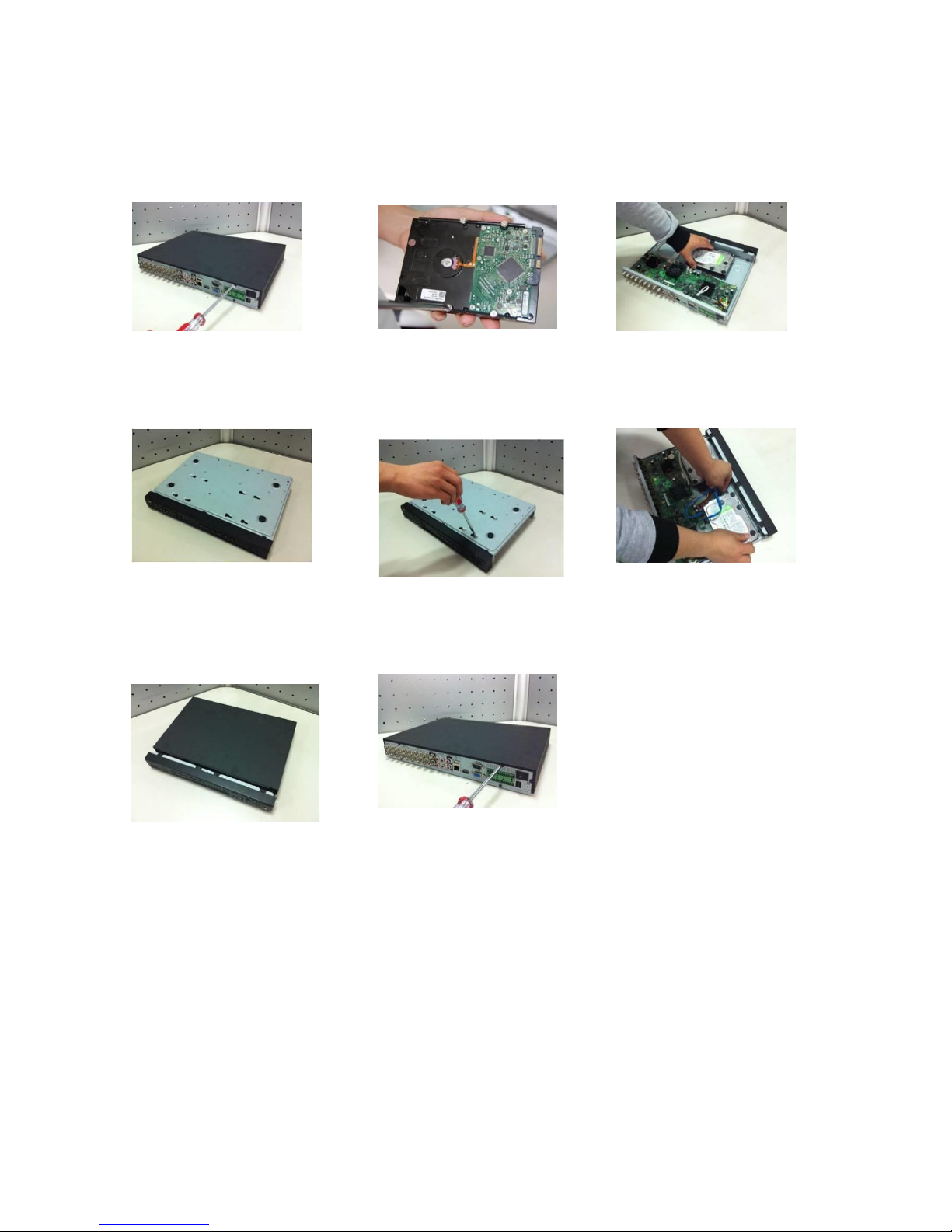
④Turn the device upside down and
then turn the screws in firmly.
⑤Fix the HDD firmly. ⑥Connect the HDD cable and
power cable.
⑦Put the cover in accordance with the
clip and then place the upper cover
back.
⑧Secure the screws in the rear panel
and the side panel.
Important:
You can connect the HDD data cable and the power cable first and then fix the HDD
in the device.
Please pay attention to the front cover. It adopts the vertical sliding design. You need
to push the clip first and then put down.
3.3.3 Compact 1U and Mini 1U Series
The series DVR has one SATA HDD.
①Loosen the screws of the upper cover
and side panel.
②
Fix four screws in the HDD (Turn
just three rounds).
③Place the HDD in accordance
with the four holes in the bottom.
3.3 HDD Installation
Page 24

217
3.4 Connecting Power Supply
Please check input voltage and device power button match or not.
We recommend you use UPS to guarantee steady operation, DVR life span, and other
peripheral equipments operation such as cameras.
3.5 Connecting Video Input and Output Devices
3.5.1 Connecting Video Input
The video input interface is BNC. The input video format includes: PAL/NTSC BNC
(1.0VB
P- P ,
B75Ω.).
The input video format: BNC(0.8VP-P,75Ω),
The video signal should comply with your national standards.
The input video signal shall have high SNR, low distortion; low interference, natural color
and suitable lightness.
Guarantee the stability and reliability of the camera signal:
The camera shall be installed in a cool, dry place away from direct sunlight, inflammable,
explosive substances and etc.
The camera and the DVR should have the same grounding to ensure the normal
operation of the camera.
Guarantee stability and reliability of the transmission lineBTTTB
Please use high quality, sound shielded BNC. Please select suitable BNC model
according to the transmission distance.
If the distance is too long, you should use twisted pair cable, and you can add video
compensation devices or use optical fiber to ensure video quality.
You should keep the video signal away from the strong electromagnetic interference,
especially the high tension current.
Keep connection lugs in well contactBTTTB
The signal line and shielded wire should be fixed firmly and in well connection. Avoid dry
joint, lap welding and oxidation.BTTT
3.5.2 Connecting Video Output
Video output includes a TBNC(PAL/NTSC, 1.0VP- P, 75Ω)output, a VGA output and a
HDMI output.
System supports BNC, VGA and HDMI output at the same time.
When you are using pc-type monitor to replace the monitor, please pay attention to the
following points:
To defer aging, do not allow the pc monitor to run for a long time.
Regular demagnetization will keep device maintain proper status.
Page 25

218
Keep it away from strong electromagnetic interference devices.
Using TV as video output device is not a reliable substitution method. You also need to
reduce the working hour and control the interference from power supply and other devices.
The low quality TV may result in device damage.
3.6 Connecting Audio Input & Output, Bidirectional Audio
3.6.1 Audio Input
BNC port is adopted for audio input port.
Due to high impedance of audio input, please use active sound pick-up.
Audio transmission is similar to video transmission. Try to avoid interference, dry joint,
loose contact and it shall be away from high tension current.
3.6.2 Audio Output
The audio output signal parameter is usually over 200mv 1KΩ (BNC). It can directly
connect to low impedance earphone, active sound box or amplifier-drive audio output
device.
If the sound box and the pick-up cannot be separated spatially, it is easy to arouse
squeaking. In this case you can adopt the following measures:
Use better sound pick-up with better directing property.
Reduce the volume of the sound box.
Using more sound-absorbing materials in decoration can reduce voice echo and
improve acoustics environment.
Adjust the layout to reduce happening of the squeaking.
3.7 Alarm Input and Output Connection
Please read the followings before connecting.
1. Alarm input
a. Please make sure alarm input mode is grounding alarm input.
b. Grounding signal is needed for alarm input.
c.Alarm input needs the low level voltage signal.
d. Alarm input mode can be either NC (normal Open) or NO (Normal Close)
e. When you are connecting two DVRs or you are connecting one DVR and one other
device, please use a relay to separate them,
2. Alarm output
The alarm output port should not be connected to high power load directly (It shall be less
than 1A) to avoid high current which may result in relay damage. Please use the co
contactor to realize the connection between the alarm output port and the load.
3. How to connect PTZ decoder
a. Ensure the decoder has the same grounding with DVR, otherwise you may not control
the PTZ. Shielded twisted wire is recommended and the shielded layer is used to connect
to the grounding.
b. Avoid high voltage. Ensure proper wiring and some thunder protection measures.
Page 26
219
c. For too long signal wires, 120Ω should be parallel connected between A, B lines on the
far end to reduce reflection and guarantee the signal quality.
d. “485 A, B” of DVR cannot parallel connect with “485 port” of other device.
e. The voltage between of A,B lines of the decoder should be less than 5v.
4. Please make sure the front-end device has soundly earthed.
Improper grounding may result in chip damage.
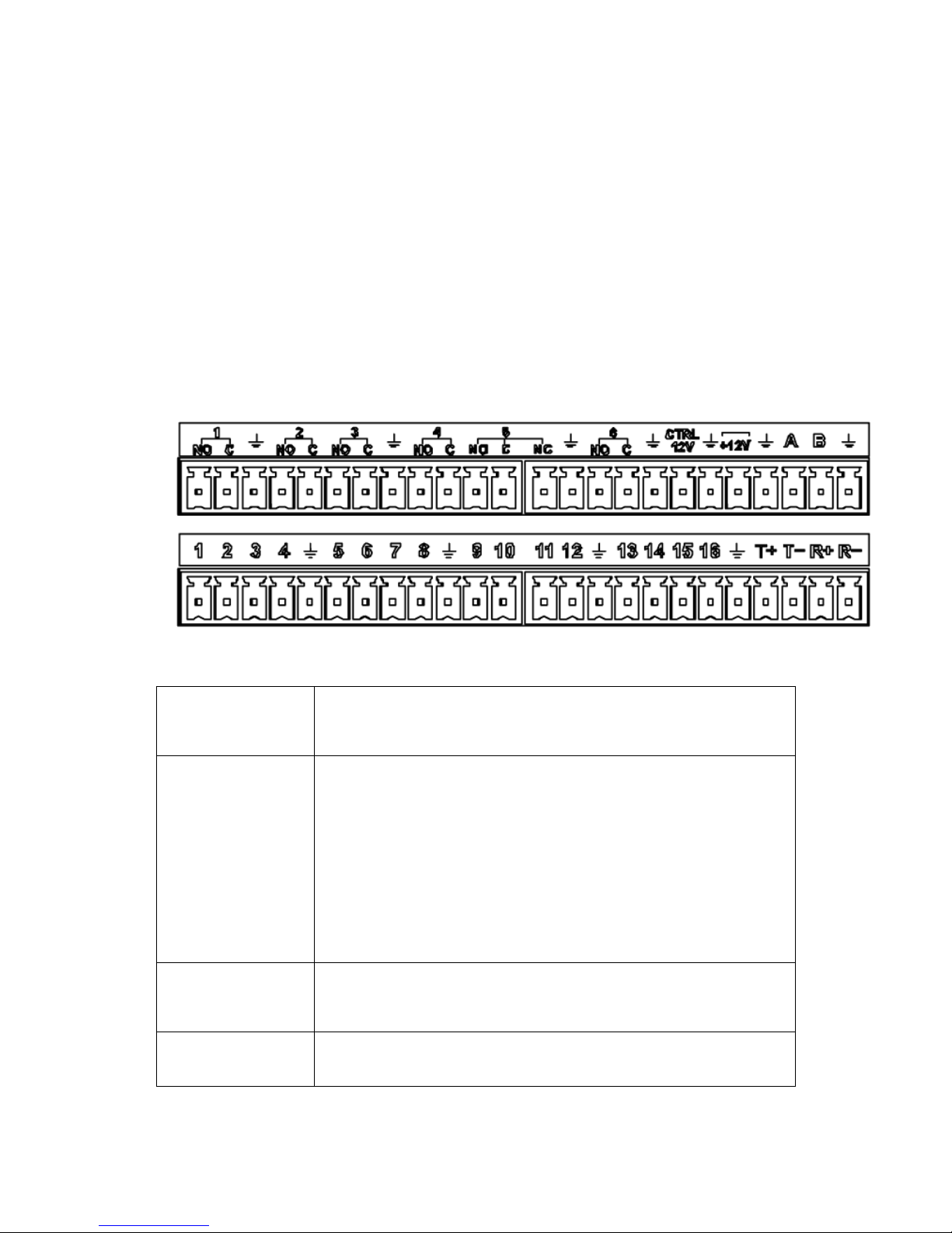
3.7.1 Alarm Input and Output Details
Important
Please refer to the specifications for the alarm input and output channel amount.
Do not merely count the alarm input and out channel amount according to the ports
on the rear panel.
Figure 3-1
1,2,3,4,5,6,
7,8,9,10,11,
12,13,14,15,16
ALARM 1 to ALARM 16. The alarm becomes active in low voltage.
In the second line,
from the left to the
right:
NO1 C1,
NO2 C2,
NO3 C3,
NO4 C4,
NO5 C5,
NO6 C6.
There are six groups of normal open activation output (on/off button)
CTRL 12V
Control power output. For external alarm, you need to close the
device power to cancel the alarm.
Voltage current;500mA.
+12V
Rated current.
Voltage current;500mA.
Page 27
220
Earth cable.
485 A/B
485 communication port. They are used to control devices such as
decoder. 120Ω should be parallel connected between A, B lines if
there are too many PTZ decoders.
T+,T-,R+,R-
They are four-wire full-duplex RS485 port
T+ T-: output wire
R+ R-: input wire
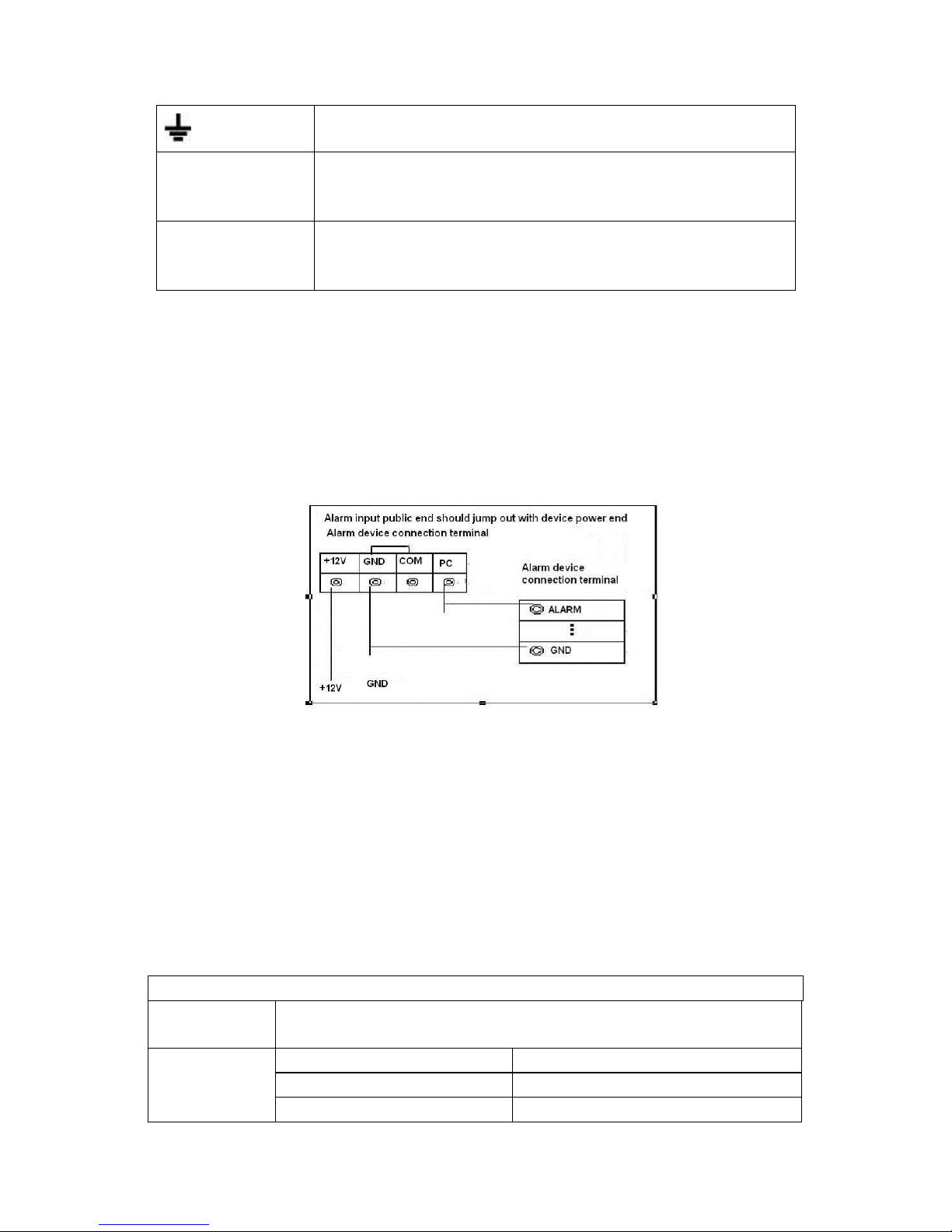
3.7.2 Alarm Input Port
Please refer to the following sheet for more information.
Grounding alarm inputs. Normal open or Normal close type)
Please parallel connect COM end and GND end of the alarm detector (Provide
external power to the alarm detector).
Please parallel connect the Ground of the DVR and the ground of the alarm detector.
Please connect the NC port of the alarm sensor to the DVR alarm input(ALARM)
Use the same ground with that of DVR if you use external power to the alarm device.
Figure 3-2
3.7.3 Alarm Output Port
Provide external power to external alarm device.
To avoid overloading, please read the following relay parameters sheet carefully.
RS485 A/B cable is for the A/B cable of the PTZ decoder.
T+,T-,R+,R- are four-wire double duplex RS485 port.
T+ T-: output wire
R+ R-: input wire
Relay Specification
Model:
JRC-27F
Material of the
touch
Silver
Rating
(Resistance
Load)
Rated switch capacity
30VDC 2A, 125VAC 1A
Maximum switch power
125VA 160W
Maximum switch voltage
250VAC, 220VDC
Page 28

221
Maximum switch currency
1A
Insulation
Between touches with same
polarity
1000VAC 1minute
Between touches with different
polarity
1000VAC 1minute
Between touch and winding
1000VAC 1minute
Surge voltage
Between touches with same
polarity
1500V (10×160us)
Length of open
time
3ms max
Length of close
time
3ms max
Longevity
Mechanical
50×106 times (3Hz)
Electrical
200×103 times (0.5Hz)
Temperature
-40℃ ~+70℃
3.8 RS485
When the DVR receives a camera control command, it transmits that command up the coaxial
cable to the PTZ device. RS485 is a single-direction protocol; the PTZ device can’t return any
data to the unit. To enable the operation, connect the PTZ device to the RS485 (A,B) input on
the DVR.
Since RS485 is disabled by default for each camera, you must enable the PTZ settings first.
This series DVRs support multiple protocols such as Pelco-D, Pelco-P.
To connect PTZ devices to the DVR:
1. Connect RS485 A,B on the DVR rear panel.
2. Connect the other end of the cable to the proper pins in the connector on the camera.
3. Please follow the instructions to configure a camera to enable each PTZ device on the
DVR.
Figure 3-3
3.9 Other Interfaces
There are still other interfaces on the DVR, such as USB ports.
485 Port
Page 29

222
4 Overview of Navigation and Controls
4.1 Boot up and Shutdown
4.1.1 Boot up
Before the boot up, please make sure:
The rated input voltage matches the device power on-off button. Please make sure
the power wire connection is OK. Then click the power on-off button.
Always use the stable current, if necessary UPS is a best alternative measure.
Please follow the steps listed below to boot up the device.
Connect the device to the monitor and then connect a mouse.
Connect power cable.
Click the power button at the front or rear panel and then boot up the device. After
device booted up, the system is in multiple-channel display mode by default.
4.1.2 Shutdown
Note
When you see corresponding dialogue box “System is shutting down…” Do not click
power on-off button directly.
Do not unplug the power cable or click power on-off button to shutdown device
directly when device is running (especially when it is recording.)
There are three ways for you to log out.
a) Main menu (RECOMMENDED)
From Main Menu->Shutdown, select shutdown from dropdown list.
Click OK button, you can see device shuts down.
b) From power on-off button on the front panel or remote control
Press the power on-off button on the DVR front panel or remote control for more than 3
seconds to shutdown the device.
c) From power on-off button on the rear panel.
4.1.3 Auto Resume after Power Failure
The system can automatically backup video and resume previous working status after
power failure.
4.1.4 Replace Button Battery
Please make sure to use the same battery model if possible.
We recommend replace battery regularly (such as one-year) to guarantee system time
accuracy.
Note:
Before replacement, please save the system setup, otherwise, you may lose the
data completely!
4.2 Set/Reset Password
Page 30
223
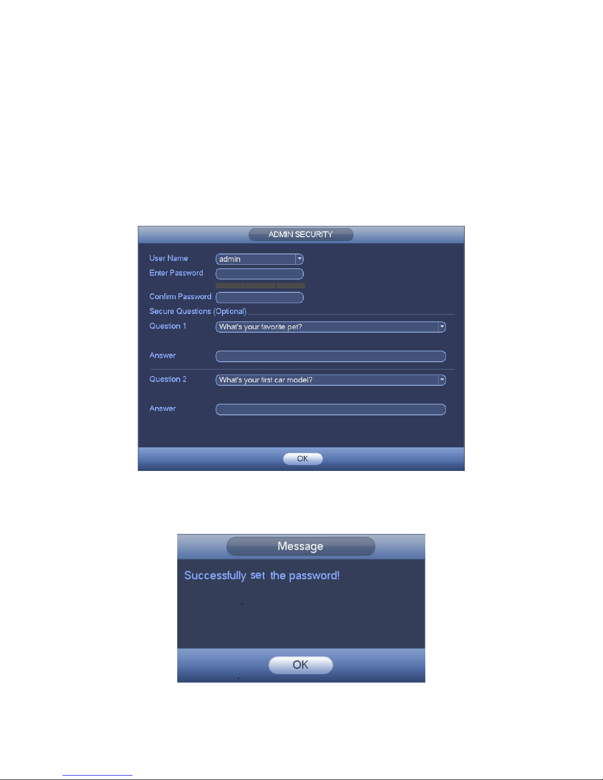
4.2.1 Set Password
For your own safety, please set your administrator default password after you first
boot up the device.
After system booted up, you can see the following interface if it is your first time to use or
you have restored default setup. See Figure 4-1. Please input a password and then input
again to set a password.
You can set security questions here to reset the password in case you forgot. System
supports customized setup. Please note you need to set two security questions at the
same time. When you reset the password, you need to answer these two security
questions too.
For reset information, please refer to chapter 4.2.2.
Figure 4-1
After you complete the setup, click OK button, system pops up the following interface for
you to confirm. Click OK button to exit. See Figure 4-2.
Figure 4-2
Page 31

224
4.2.2 Reset Password
Once you forgot password, you can answer the security questions you set in chapter 4.2.1
to reset the password.
In login interface, click . See Figure 4-3.
Figure 4-3
System pops up the following dialogue box, please answer the security questions and
then input the new password twice. See Figure 4-4.
Figure 4-4
4.3 Startup Wizard
After device successfully booted up, it goes to startup wizard.
Page 32

225
Click Cancel/Next button, you can see system goes to login interface.
Tips
Check the box Startup button here, system goes to startup wizard again when it boots up
the next time.
Cancel the Startup button, system goes to the login interface directly when it boots up the
next time.
Figure 4-5
Click Cancel button or Next Step button, system goes to login interface. See Figure 4-6.
System consists of three accounts:
Username: admin. Password: admin. (administrator, local and network)
Username: 888888. Password: 888888. (administrator, local only)
Username: default. Password: default (hidden user). Hidden user “default” is for
system interior use only and can not be deleted. When there is no login user, hidden
user “default” automatically login. You can set some rights such as monitor for this
user so that you can view some channel view without login.
Figure 4-6
Page 33

226
Caution
For security reason, please modify password after you first login.
Continuous three times login failure will result in system alarm and five times
login failure will result in account lock!
Please reboot the device or wait for 30 minutes to try again if your account has
been locked.
After input corresponding user name and password, you can click OK button. System
goes to the startup wizard.
When there are all analog channels, the startup wizard includes general, encode,
schedule, record control, network, P2P.
When there is an IP channel, the startup wizard includes general, network, P2P,
remote device and schedule.
Click OK button, you can go to General interface. See Figure 4-7.
For detailed information, please refer to chapter 4.11.5.1.
Figure 4-7
Note
You can only see the remote device interface if you have set IP channel (Chapter
4.11.1.3.5)
Click Next button, you can go to network interface. See Figure 4-8.
Page 34

227
For detailed information, please refer to chapter 4.10.3.
Figure 4-8
Click Next button, you can set P2P function. Scan the QR code, download the App to the
cellphone, you can use the smart phone to add the device. See Figure 4-9.
For detailed information, please refer to chapter4.11.2.15.
Figure 4-9
Page 35
228
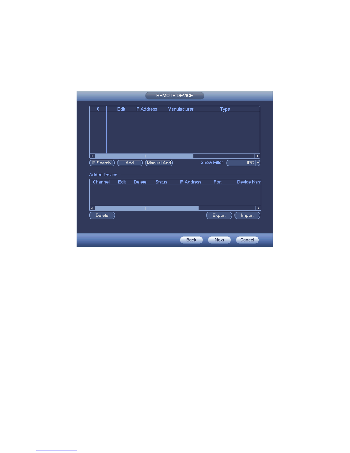
Now you can go to the remote device interface to add the camera to the corresponding
channel. See Figure 4-10.
For detailed information, please refer to chapter4.11.1.1.
Please note you can not see the following interface if there is no digital channel. You can
go to Main menu->Setting->Camera->Channel type to set IP channel first. Please refer to
chapter 4.11.1.3.5 for detailed setup information.
Figure 4-10
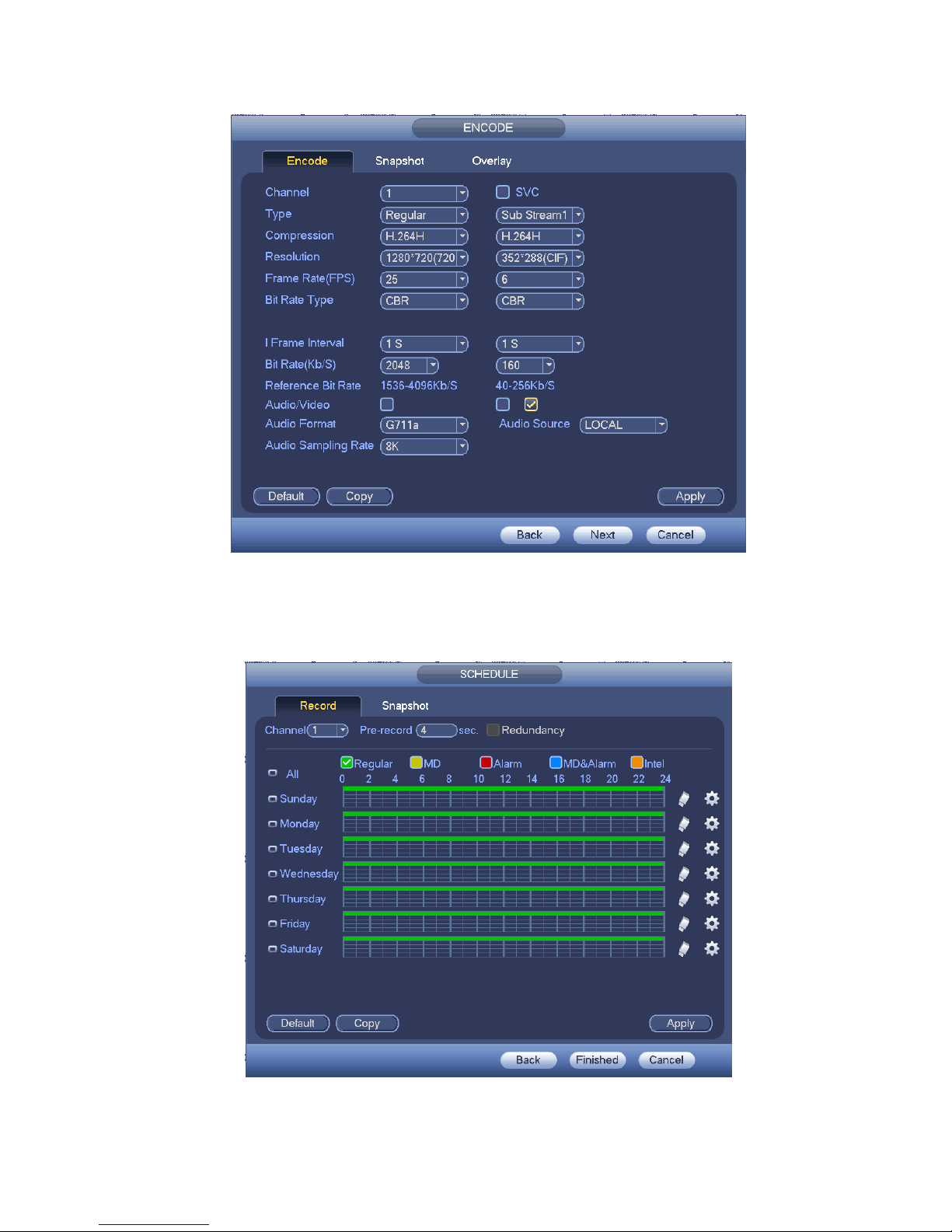
Click Next button, you can go to Encode interface. See Figure 4-11.
For detailed information, please refer to chapter 4.11.1.3.
Page 36
229
Figure 4-11
Click Next button, you can go to Schedule interface. See Figure 4-12.
For detailed information, please refer to chapter 4.11.4.1.
Figure 4-12
Page 37
230
Click Finish button, system pops up a dialogue box. Click the OK button, the startup
wizard is complete. See Figure 4-13.
Figure 4-13
4.4 Live Viewing
After you logged in, the system is in live viewing mode. You can see system date, time,
channel name and window No. If you want to change system date and time, you can
refer to general settings (Main Menu->Setting->System->General). If you want to
modify the channel name, please refer to the display settings (Main
Menu->Camera->CAM name)
Tips
Preview drag: If you want to change position of channel 1 and channel 2 when you
are previewing, you can left click mouse in the channel 1 and then drag to channel
2, release mouse you can switch channel 1 and channel 2 positions.
Use mouse middle button to control window split: You can use mouse middle
button to switch window split amount.
Please note you can not switch position of one analog channel and one digital
channel.
Preview Control
The preview control function has the following features.
Support preview playback.
In the preview desktop, system can playback previous 5-60 minutes record of
current channel. Please go to the Main Menu->General to set real-time
playback time.
Support drag and play function. You can use your mouse to select any
playback start time.
Support playback, pause and exit function.
1
Recording status
3
Video loss
2
Motion detection
4
Camera lock
Page 38
231
Right now, system does not support slow playback and backward playback
function.
Support digital zoom function.
Support real-time backup function.
You can follow the contents listed below for the operation instruction.
Preview control interface
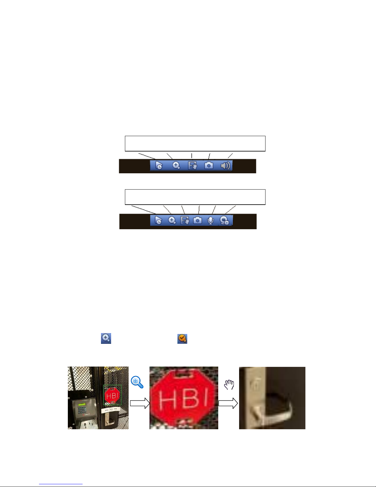
Move you mouse to the top centre of the video of current channel, you can see system
pops up the preview control interface. See Figure 4-14 and Figure 4-15. If your mouse
stays in this area for more than 6 seconds and has no operation, the control bar
automatically hides.
Figure 4-14 Analog Channel
Figure 4-15 Digital Channel
1) Realtime playback
It is to playback the previous 5-60 minutes record of current channel.
Please go to the Main menu->Setting->->System->General to set real-time playback
time.
System may pop up a dialogue box if there is no such record in current channel.
2) Digital zoom
It is to zoom in specified zone of current channel. It supports zoom in function of
multiple-channel.
Click button , the button is shown as .
There are two ways for you to zoom in.
Drag the mouse to select a zone, you can view an interface show as Figure 4-16.
Figure 4-16
1 2 3 4 5
1 2 3 4 6 7
Page 39

232
Put the middle button at the centre of the zone you want to zoom in, and move the
mouse, you can view an interface shown as in Figure 4-17 .
Figure 4-17
Right click mouse to cancel zoom and go back to the original interface.
3) Manual record function
It is to backup the video of current channel to the USB device. System can not backup
the video of multiple-channel at the same time.
Click button , system begins recording. Click it again, system stops recoridng. You
can find the record file on the flash disk.
4) Manual Snapshot
Click to snapshot 1-5 times. The snapshot file is saved on the USB device or HDD.
You can go to the Search interface (chapter 4.9.1) to view.
5) Mute (For analog channel only)
Click to mute. Click again to enable audio function when preview.
Please note this function is for one-window mode only.
6) Bidirectional talk (For digital channel only)
If the connected front-end device supports bidirectional talk function, you can click this
button. Click button to start bidirectional talk function the icon now is shown as .
Now the rest bidirectional talk buttons of digital channel becomes null too.
Click again, you can cancel bidirectional talk and the bidirectional talk buttons of
other digital channels become as .
7) Remote device (For digital channel only)
Shortcut menu. Click it to go to the remote device interface to add/delete remote
device or view its corresponding information. Please refer to chapter 4.11.1.1 for
detailed information.
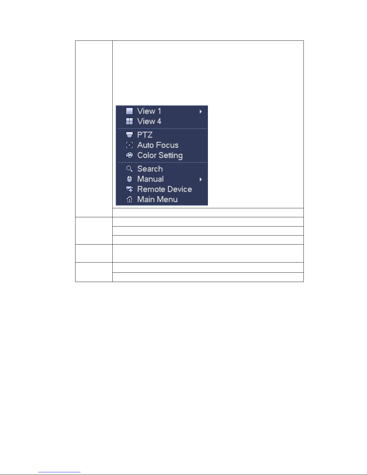
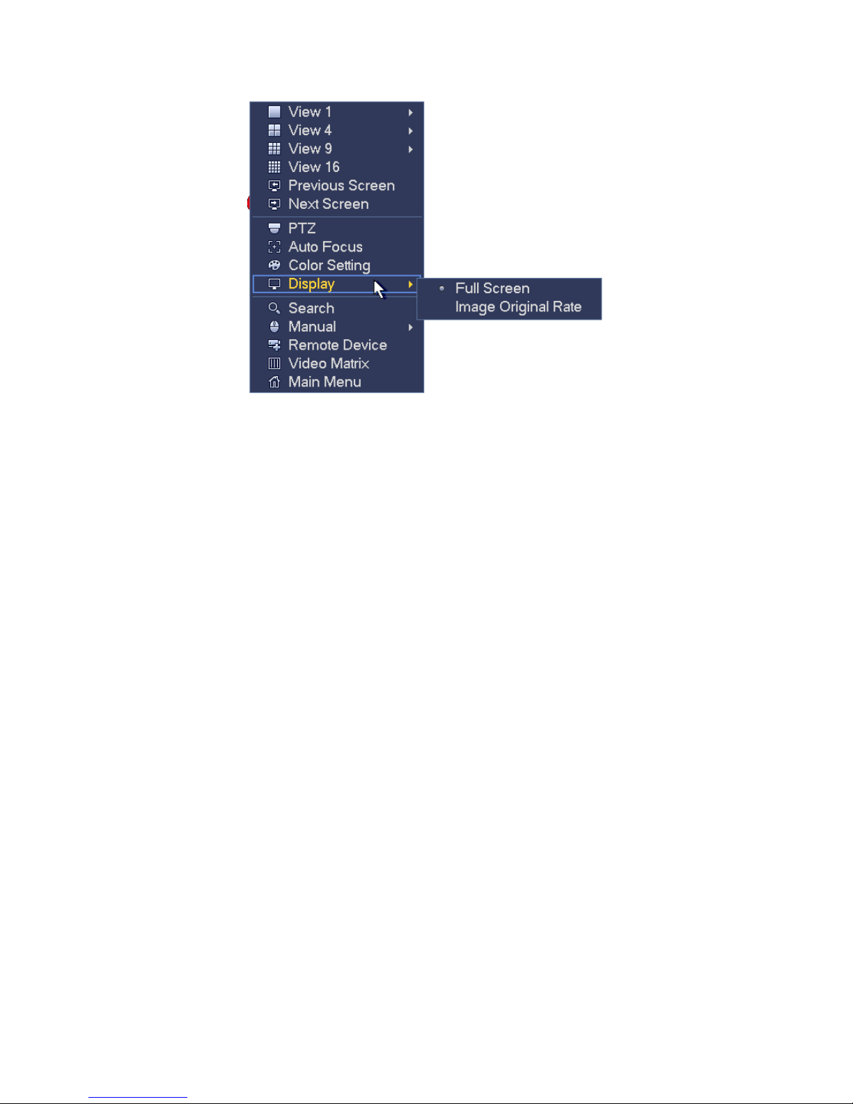
4.5 Right-Click Menu
On the preview interface, right click mouse, you can view menu interface shown as in
Figure 4-18.
Tips
Page 40

233
After you go to the corresponding interface, right click mouse to go back to the
upper-level.
Window split mode: You can select window amount and then select channels.
PTZ: Click it to go to PTZ interface.
Auto focus: Please make sure you connected network camera supports this function.
Color setting: Set video corresponding information.
Search: Click it to go to Search interface to search and playback a record file.
Record control: Enable/disable record channel.
Remote device: Click it to add remote device.
Main menu: Go to system main menu interface.
Figure 4-18
4.5.1 Window Switch
System supports 1/4/8/9-window (The options here depend on your product channel
amount). You can select from the dropdown list. See Figure 4-19.
Page 41

234
Figure 4-19
4.5.2 Previous Screen/Next Screen
Click it to go to the previous screen/next screen. For example, if you are using 4-split
mode, the first screen is displaying the channel 1-4, click Next screen, you can view
channel 5-8.
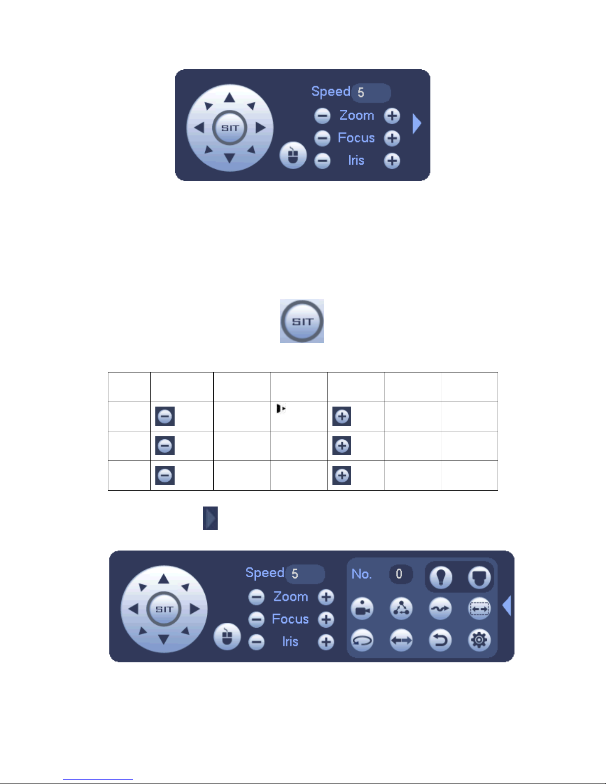
4.5.3 PTZ Control
The PTZ setup is shown as in See Figure 4-20.
Please note the commend name is grey once device does not support this function.
The PTZ operation is only valid in one-window mode.
Here you can control PTZ direction, speed, zoom, focus, iris, preset, tour, scan, pattern
aux function, light and wiper, rotation and etc.
Speed is to control PTZ movement speed. The value ranges from 1 to 8.The speed 8 is
faster than speed 1. You can use the remote control to click the small keyboard to set.
You can click and of the zoom, focus and iris to zoom in/out, definition and
brightness.
The PTZ rotation supports 8 directions. If you are using direction buttons on the front
panel, there are only four directions: up/down/left/right.
Page 42
235
Figure 4-20
In the middle of the eight direction arrows, there is a 3D intelligent positioning key. See
Figure 4-21. Please make sure your protocol supports this function and you need to use
mouse to control.
Click this key, system goes back to the single screen mode. Drag the mouse in the screen
to adjust section size. The dragged zone supports 4X to 16X speeds. It can realize PTZ
automatically. The smaller zone you dragged, the higher the speed.
Figure 4-21
Name
Function
key
function
Shortcut
key
Function
key
function
Shortcut
key
Zoom
Near
Far
Focus
Near
│
Far
►│
Iris close
Open
In Figure 4-20, click to open the menu, you can set preset, tour, pattern, scan and
etc. See Figure 4-22.
Figure 4-22
Please refer to the following sheet for detailed information.
Page 43

236
Please note the above interface may vary due to different protocols. The button is grey
and can not be selected once the current function is null.
Right click mouse or click the ESC button at the front panel to go back to the Figure
4-20.
Icon
Function
Icon
Function
Preset
Flip
Tour
Reset
Pattern
Aux
Scan
Aux on-off
button
Rotate
Go to menu
4.5.3.1 PTZ Function Setup
Click , you can go to the following interface to set preset, tour, pattern, and scan. See
Figure 4-23.
Figure 4-23
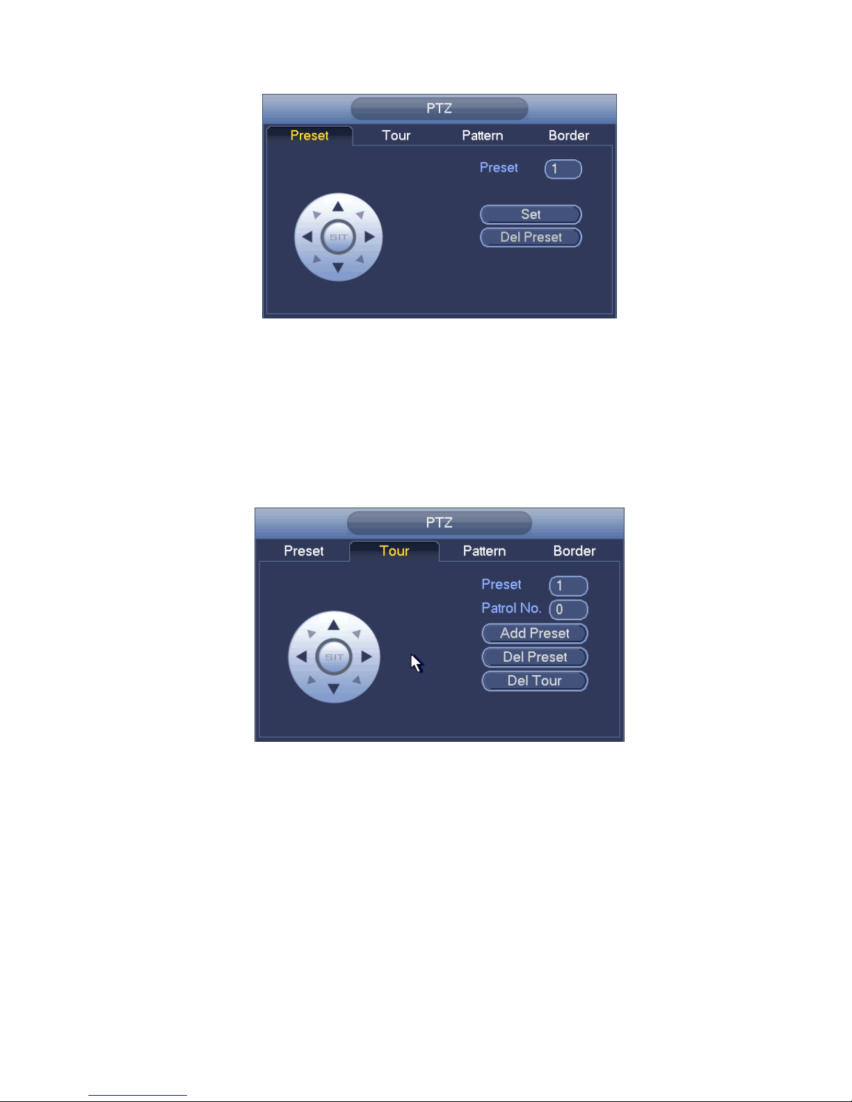
Preset Setup
In Figure 4-23, click preset button and use eight direction arrows to adjust camera to the
proper position. The interface is shown as in Figure 4-24.
Click Set button and then input preset number.
Click Set button to save current preset.
Page 44
237
Figure 4-24
Tour Setup
In Figure 4-23, click tour button.
Input tour value and preset No. Click Add preset button to add current preset to the tour.
See Figure 4-25.
Tips
Repeat the above steps to add more presets to the tour. Click Del preset button to remove
it from the tour. Please note some protocols do not support delete preset function.
Figure 4-25
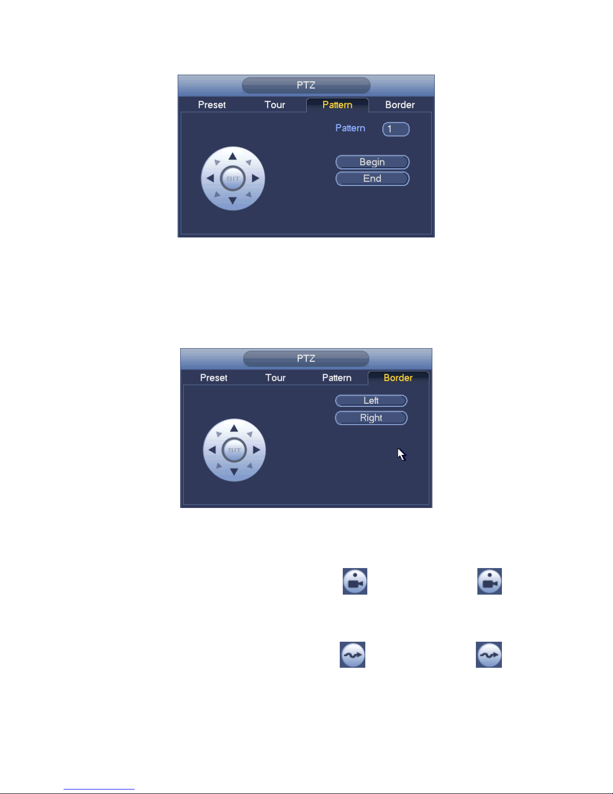
Pattern Setup
In Figure 4-23, click Pattern button and input pattern number.
Click Begin button to start direction operation. Or you can go back to Figure 4-20 to
operate zoom/focus/iris/direction operation.
In Figure 4-23, click End button.
Page 45
238
Figure 4-26
Scan Setup
In Figure 4-23, click Scan button.
Use direction buttons to set camera left limit and then click Left button.
Use direction buttons to set camera right limit and then click Right button. Now the scan
setup process is complete.
Figure 4-27
4.5.3.2 Call PTZ Function
Call Preset
In Figure 4-22, input preset value and then click to call a preset. Click
again to stop call.
Call Pattern
In Figure 4-22 , input pattern value and then click to call a pattern. Click
again to stop call.
Call Tour
Page 46
239
In Figure 4-22, input tour value and then click to call a tour. Click again
to stop call.
Call Scan
In Figure 4-22, input Scan value and then click to call a tour. Click again
to stop call.
Rotate
In Figure 4-22 , click to enable the camera to rotate.
System supports preset, tour, pattern, scan, rotate, light and etc function.
Note:
Preset, tour and pattern all need the value to be the control parameters. You can
define it as you require.
You need to refer to your camera user’s manual for Aux definition. In some cases, it
can be used for special process.
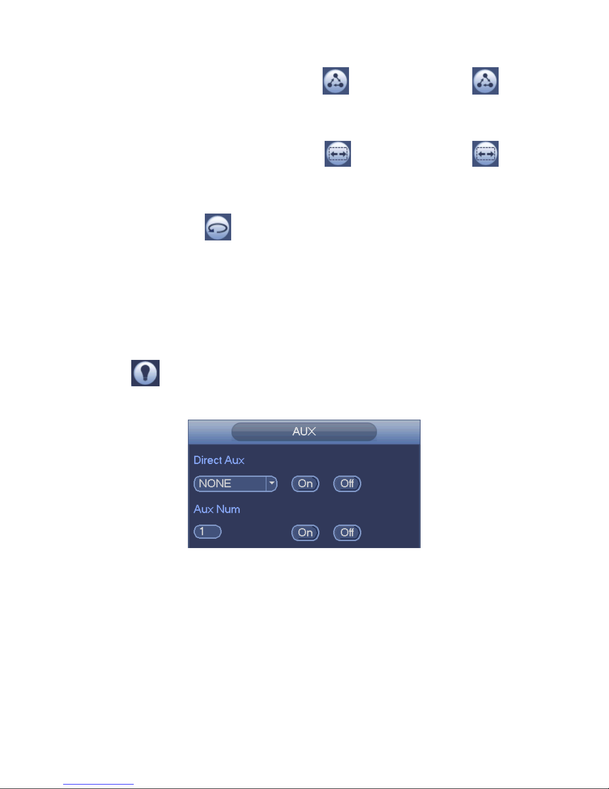
Aux
Click , system goes to the following interface. The options here are defined by the
protocol. The aux number is corresponding to the aux on-off button of the decoder. See
Figure 4-28.
Figure 4-28
4.5.4 Auto Focus
It is to set auto focus function. Please make sure the camera supports this function.
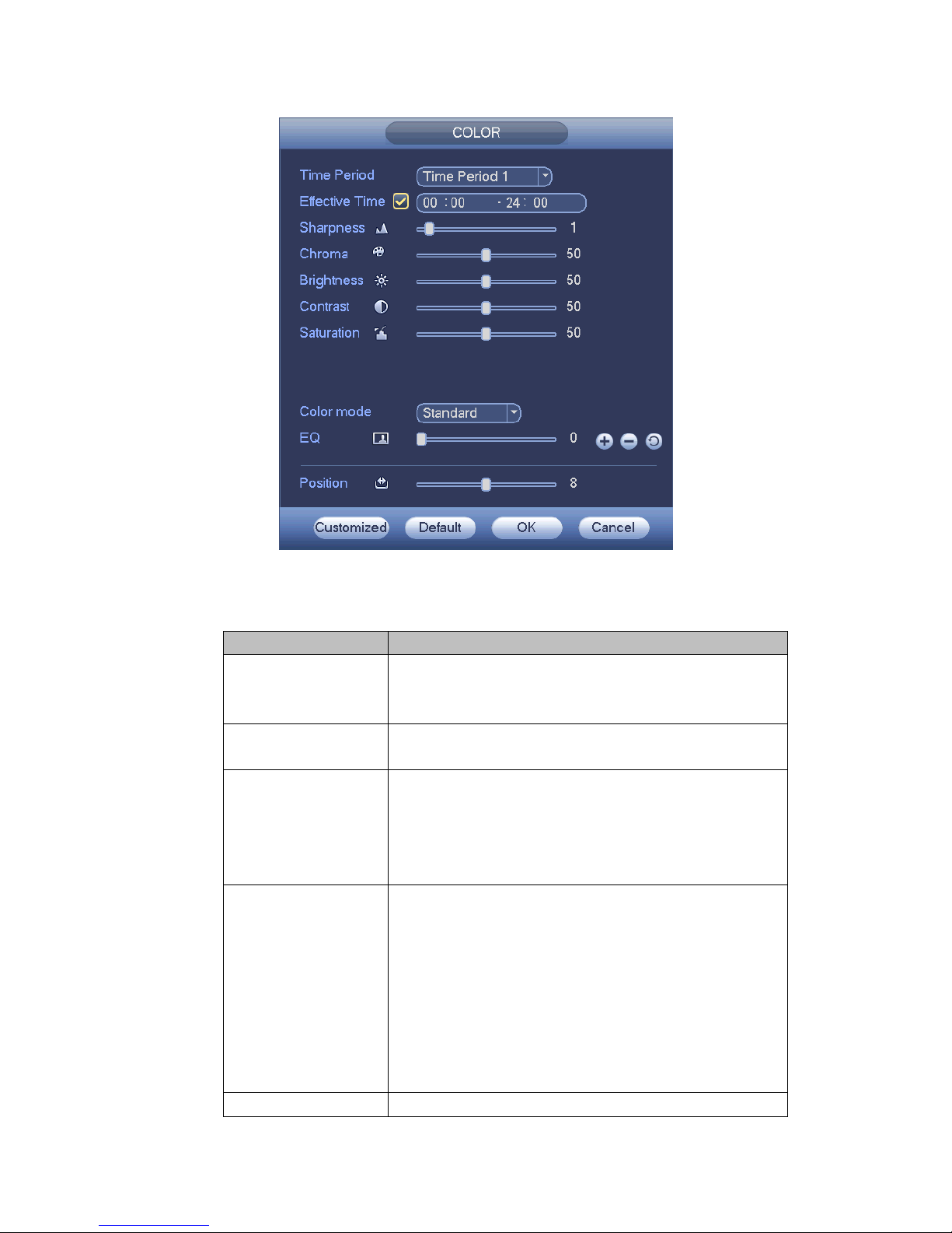
4.5.5 Color
Here you can set hue, brightness, contrast, saturation, gain, white level, color mode
and etc. See Figure 4-29.
Page 47
240
Figure 4-29
Please refer to the following sheet for detailed information.
Item
Note
Period
There are two periods in one day. You can set different
sharpness, brightness, and contrast setup for different
periods.
Effective Time
Check the box here to enable this function and then set
period time.
Sharpness
The value here is to adjust the edge of the video. The
value ranges from 0 to 100. The larger the value is, the
clear the edge is and vice versa. Please note there is
noise if the value here is too high. The default value is 50
and the recommended value ranges from 40 to 60.
Brightness
It is to adjust monitor window bright. The value ranges
from 0 to 100. The default value is 50.
The larger the number, the bright the video is. When you
input the value here, the bright section and the dark
section of the video will be adjusted accordingly. You
can use this function when the whole video is too dark or
too bright. Please note the video may become hazy if the
value is too high. The recommended value ranges from
40 to 60.
Contrast
It is to adjust monitor window contrast. The value ranges
Page 48

241
Item
Note
from 0 to 100. The default value is 50.
The larger the number, the higher the contrast is. You
can use this function when the whole video bright is OK
but the contrast is not proper. Please note the video may
become hazy if the value is too low. If this value is too
high, the dark section may lack brightness while the
bright section may over exposure .The recommended
value ranges from 40 to 60.
Saturation
It is to adjust monitor window saturation. The value
ranges from 0 to 100. The default value is 50.
The larger the number, the strong the color is. This value
has no effect on the general brightness of the whole
video. The video color may become too strong if the
value is too high. For the grey part of the video, the
distortion may occur if the white balance is not accurate.
Please note the video may not be attractive if the value
is too low. The recommended value ranges from 40 to
60.
Gain
The gain adjust is to set the gain value. The default
value may vary due to different device models. The
smaller the value, the low the noise. But the brightness is
also too low in the dark environments. It can enhance
the video brightness if the value is high. But the video
noise may become too clear.
Color mode
It includes several modes such as standard, color, bright,
gentle. Select a color mode, the sharpness, brightness,
contrast and etc can automatically switch to
corresponding setup.
EQ
Click or to adjust image equalization value.
Click reset button , system can auto adjust the video
to the best effect.
This function is for analog channel only.
Image position
It is to adjust the image position on the screen. The
value here refers to the pixel. The default pixel value is
16.
This function is for analog channel only.
4.5.6 Display
It is to set display output mode. There are two modes: full screen (4:3)/image original rate
(16:9). Icon means current display output mode. See Figure 4-30.
Page 49
242
Figure 4-30
4.5.7 Face Search
It is to display human face record list, and view human face recognition record file.
4.5.8 Search
Please refer to chapter 4.9.1 for detailed information.
4.5.9 Record Control
Please refer to chapter 4.11.4.3 for detailed information.
4.5.10 Alarm Output
Please refer to chapter 4.11.3.6 for detailed information.
4.5.11 Remote Device
Please refer to chapter 4.11.1.1 for detailed information.
4.5.12 Video Matrix
Please refer to chapter 4.11.5.3 for detailed information.
4.5.13 Main menu
Please refer to chapter 4.8 for detailed information.
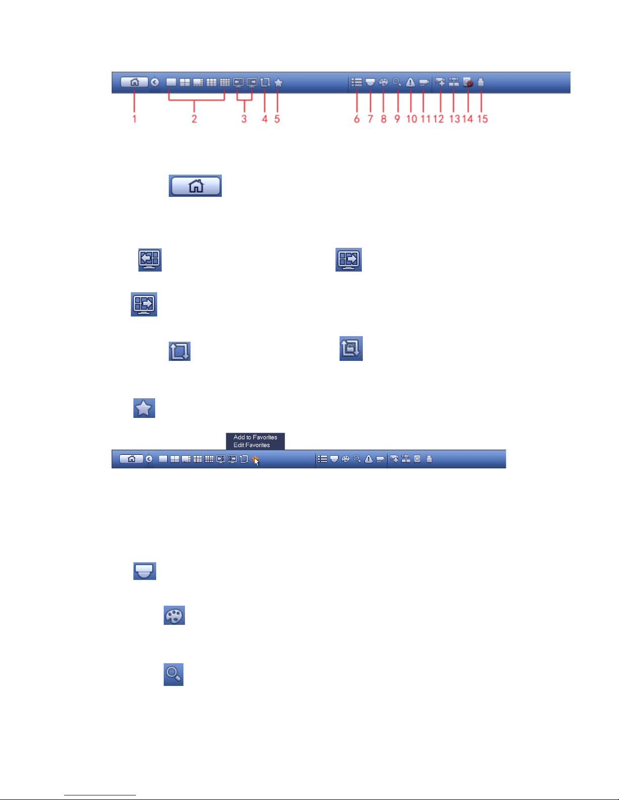
4.6 Navigation Bar
You need to go to the Main menu->Setting->System->General to enable navigation
bar function; otherwise you can not see the following interface.
The navigation bar is shown as below. See Figure 4-31.
Page 50
243
Figure 4-31
4.6.1 Main Menu
Click button to go to the main menu interface.
4.6.2 Output Screen
Select corresponding window-split mode and output channels.
4.6.3 Previous/Next Screen
Click to go to the previous screen, click to go to the next screen. For
example, if you are using 4-split mode, the first screen is displaying the channel 1-4,
click , you can view channel 5-8.
4.6.4 Tour
Click button to enable tour, the icon becomes , you can see the tour is in
process.
4.6.5 Favorites
Click , system pops up add/edit favorites. See Figure 4-32.
Figure 4-32
4.6.6 Channel
It is to pop up channel tree. You can left click to select a channel on the tree and then drag
it to the preview window on the left pane.
4.6.7 PTZ
Click , system goes to the PTZ control interface. Please refer to chapter 4.5.3.
4.6.8 Color
Click button , system goes to the color interface. Please refer to chapter 4.5.5.
4.6.9 Search
Click button , system goes to search interface. Please refer to chapter 4.9.1
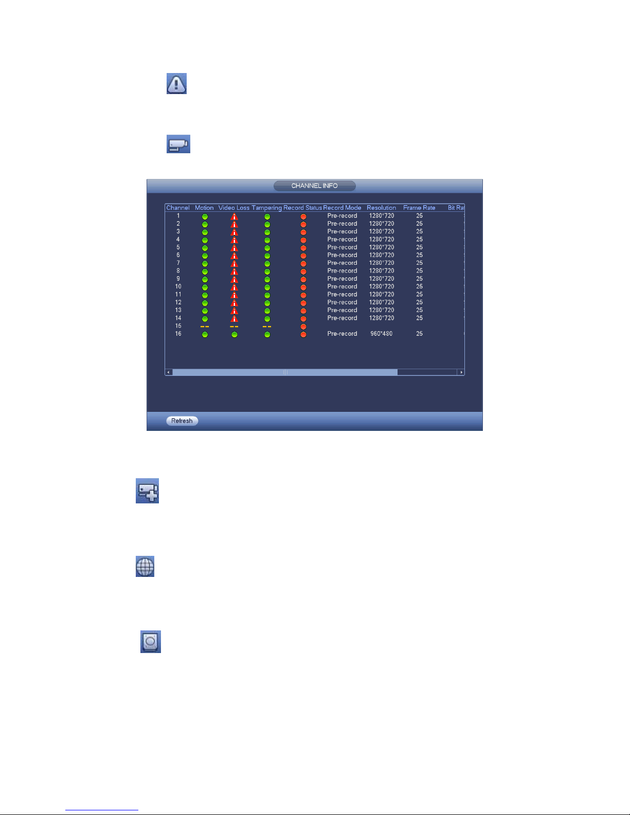
4.6.10 Alarm Status
Page 51
244
Click button , system goes to alarm status interface. It is to view device status and
channel status. Please refer to chapter 4.11.3.
4.6.11 Channel Info
Click button , system goes to the channel information setup interface. It is to view
information of the corresponding channel. See Figure 4-33.
Figure 4-33
4.6.12 Remote Device
Click , system goes to an interface for you to view remote device information. Please
refer to chapter 4.11.1.1.
4.6.13 Network
Click , system goes to the network interface. It is to set network IP address, default
gateway and etc. Please refer to chapter 4.11.2.
4.6.14 HDD Manager
Click , system goes to the HDD manager interface. It is to view and manage HDD
information. Please refer to chapter 4.11.4.2.
4.6.15 USB Manager
Page 52

245
Click , system goes to the USB Manager interface. It is to view USB information,
backup and update. Please refer to chapter 4.9.3, chapter 4.10.4, chapter 4.11.5.10, and
chapter 4.11.5.12 for detailed information.
4.7 USB Device Auto Pop-up
After you inserted the USB device, system can auto detect it and pop up the following
dialogue box. It allows you to conveniently backup file, log, configuration or update
system. See Figure 4-34. Please refer to chapter 4.9.3, chapter 4.10.4, chapter 4.11.5.10,
and chapter 4.11.5.12 for detailed information.
Figure 4-34
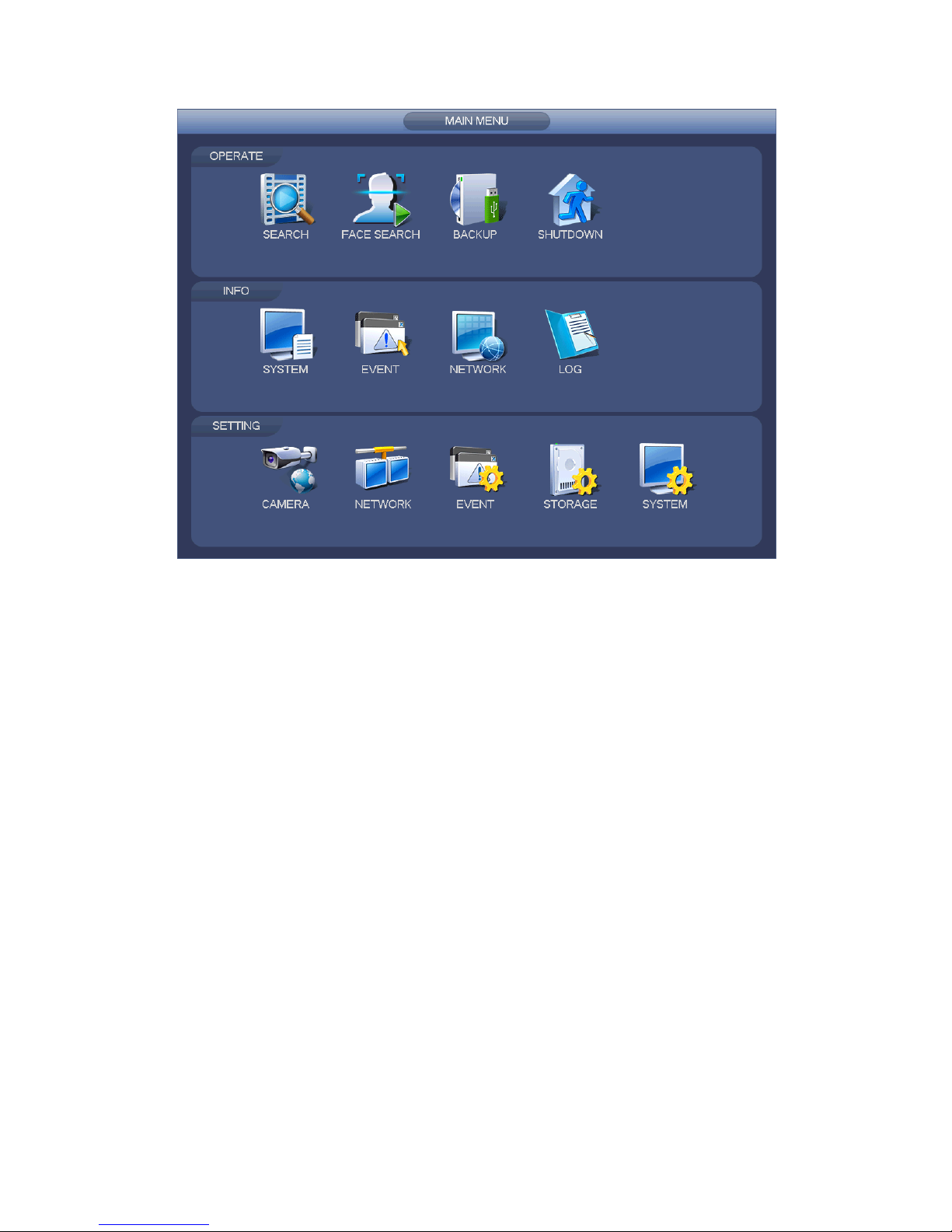
4.8 Main Menu
The main menu interface is shown as below. See Figure 4-35.
Page 53
246
Figure 4-35
4.9 Operation
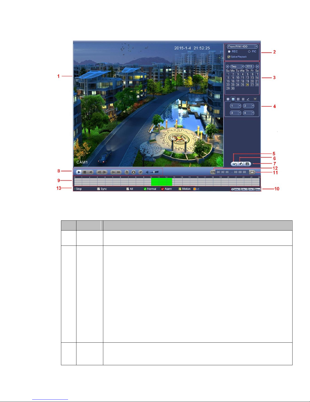
4.9.1 Search
Click search button in the main menu, search interface is shown as below. See Figure
4-36.
Usually there are three file types:
R: Regular recording file.
A: External alarm recording file.
M: Motion detection recording file
Orange: Intelligent recording file.
Page 54
247
Figure 4-36
Please refer to the following sheet for more information.
SN
Name
Function
1
Display
window
Here is to display the searched picture or file.
Support 1/4/9/16-window playback.
2
Search
type
Here you can select to search the picture or the recorded file.
You can select to play from the read-write HDD, from peripheral device or from
redundancy HDD.
Before you select to play from the peripheral device, please connect the
corresponding peripheral device. You can view all record files of the root directory
of the peripheral device. Click the Browse button; you can select the file you want to
play.
Check the box here; you can enable splice playback function. Please refer to
chapter 4.9.1.4 for detailed information.
Important
Redundancy HDD does not support picture backup function, but it
supports picture playback function. You can select to play from redundancy
HDD if there are pictures on the redundancy HDD.
3
Calendar
The blue highlighted date means there is picture or file. Otherwise, there is no
picture or file.
In any play mode, click the date you want to see, you can see the
Page 55

248
corresponding record file trace in the time bar.
4
Playback
mode
and
channel
selection
pane.
Playback mode:1/4/9/16/customized. (It may vary due to different series.)
In 1-window playback mode: you can select 1-16 channels.
In 4-window playback mode: you can select 4 channels according to your
requirement.
In 9-window playback mode, you can switch between 1-8 and 9-16 channels.
In 16-window playback mode, you can switch between1-16 and 17-32
channels.
In customized mode, you can select one or more channel(s) you want to
playback at the same time. See chapter 4.9.1.4.
The time bar will change once you modify the playback mode or the channel
option.
5
Card
number
search
The card number search interface is shown as below. Here you can view card
number/field setup bar. You cam implement advanced search.
6
Mark file
list button
Click it to go to mark file list interface. You can view all mark information of current
channel by time. Please refer to chapter 4.9.1.3 for detailed information.
Please note only the product of this icon supports mark function.
7
File list
switch
button
Double click it, you can view the picture/record file list of current day.
The file list is to display the first channel of the record file.
The system can display max 128 files in one time. Use the │and │ or the
mouse to view the file. Select one item, and then double click the mouse or click the
ENTER button to playback.
You can input the period in the following interface to begin accurate search.
File type:R—regular record; A—external alarm record;M—Motion detect
record.
Lock file. Click the file you want to lock and click the button to lock. The
file you locked will not be overwritten.
Search locked file: Click the button to view the locked file.
8
Playback
control
pane.
►/
Play/Pause
There are three ways for you to begin playback.
The play button
Double click the valid period of the time bar.
Double click the item in the file list.
In slow play mode, click it to switch between play/pause.
■
Stop
Backward play
In normal play mode, left click the button, the file begins backward play.
Page 56
249
Click it again to pause current play.
In backward play mode, click ►/ to restore normal play.
│/
│
In playback mode, click it to play the next or the previous section. You can
click continuously when you are watching the files from the same channel.
In normal play mode, when you pause current play, you can click │ and
│ to begin frame by frame playback.
In frame by frame playback mode, click ►/ to restore normal playback.
►
Slow play
In playback mode, click it to realize various slow play modes such as slow
play 1, slow play 2, and etc.
Fast forward
In playback mode, click to realize various fast play modes such as fast
play 1,fast play 2 and etc.
Note: The actual play speed has relationship with the software version.
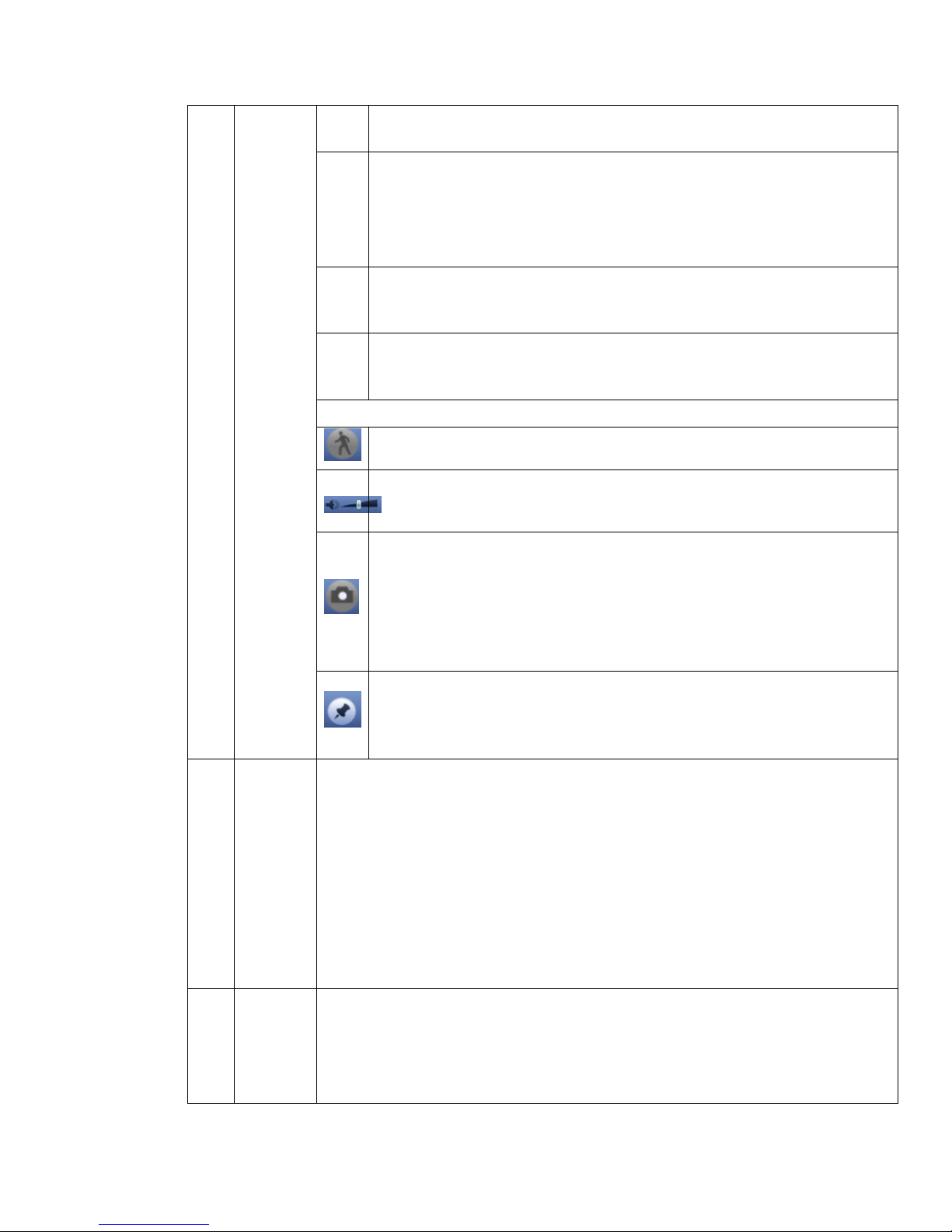
Smart search
The volume of the playback
Click the snapshot button in the full-screen mode, the system can snapshot
1 picture.
System supports custom snap picture saved path. Please connect the
peripheral device first, click snap button on the full-screen mode, you can
select or create path. Click Start button, the snapshot picture can be saved
to the specified path.
Mark button.
Please note this function is for some series product only. Please make sure
there is a mark button in the playback control pane.
You can refer to chapter 4.9.1.3 for detailed information.
9
Time bar
It is to display the record type and its period in current search criteria.
In 4-window playback mode, there are corresponding four time bars. In other
playback mode, there is only one time bar.
Use the mouse to click one point of the color zone in the time bar, system
begins playback.
The time bar is beginning with 0 o'clock when you are setting the configuration.
The time bar zooms in the period of the current playback time when you are playing
the file.
The green color stands for the regular record file. The red color stands for the
external alarm record file. The yellow stands for the motion detect record file.
10
Time bar
unit
●The option includes: 24H, 12H, 1H and 30M. The smaller the unit, the larger the
zoom rate. You can accurately set the time in the time bar to playback the record.
The time bar is beginning with 0 o'clock when you are setting the configuration.
The time bar zooms in the period of the current playback time when you are playing
the file.
Page 57

250
11
Backup
Select the file(s) you want to backup from the file list. You can check from the
list. Then click the backup button, now you can see the backup menu. System
supports customized path setup. After select or create new folder, click the
Start button to begin the backup operation. The record file(s) will be saved in
the specified folder.
Check the file again you can cancel current selection. System max supports to
display 32 files from one channel.
After you clip on record file, click Backup button you can save it.
For one device, if there is a backup in process, you can not start a new backup
operation.
12
Clip
It is to edit the file.
●Please play the file you want to edit and then click this button when you want to
edit. You can see the corresponding slide bars in the time bar of the corresponding
channel. You can adjust the slide bar or input the accurate time to set the file end
time.
After you set, you can click Clip button again to edit the second period. You can
see the slide bar restore its previous position.
Click Backup button after clip, you can save current contents in a new file.
You can clip for one channel or multiple-channel. The multiple-channel click
operation is similar with the one-channel operation.
Please note:
System max supports 1024 files backup at the same time.
You can not operate clip operation if there is any file has been checked in
the file list.
13
Record
type
In any play mode, the time bar will change once you modify the search type.
Other Functions
14
Smart
search
When system is playing, you can select a zone in the window to begin smart
search. Click the motion detect button to begin play.
Once the motion detect play has begun, click button again will terminate
current motion detect file play.
There is no motion detect zone by default.
If you select to play other file in the file list, system switches to motion detect
play of other file.
During the motion detect play process, you can not implement operations such
as change time bar, begin backward playback or frame by frame playback.
Please refer to chapter 4.9.1.1 Smart Search for detailed operation.
15
Other
channel
synchroni
zation
switch to
play
When playing the file, click the number button, system can switch to the same
period of the corresponding channel to play.
Page 58

251
when
playback
16
Sync
In pane 13 of Figure 4-36, click Sync button, you can playback the files of different
channels occurred at the same time.
17
Digital
zoom
When the system is in full-screen playback mode, left click the mouse in the
screen. Drag your mouse in the screen to select a section and then left click
mouse to realize digital zoom. You can right click mouse to exit.
18
Manually
switch
channel
when
playback
During the file playback process, you can switch to other channel via the
dropdown list or rolling the mouse.
This function is null if there is no record file or system is in smart search process.
4.9.1.1 Smart Search
During the multiple-channel playback mode, double click one channel and then click the
button, system begins smart search. System supports 396(22*18 PAL) and
330(22*15 NTSC) zones. Please left click mouse to select smart search zones. See
Figure 4-37.
Figure 4-37
Click the , you can go to the smart search playback. Click it again, system stops
smart search playback.
Important
System does not support motion detect zone setup during the full-screen
mode.
Page 59

252
During the multiple-channel playback, system stops playback of rest channels
if you implement one-channel smart search.
4.9.1.2 Accurate playback by time
Select records from one day, click the list, you can go to the file list interface. You can
input time at the top right corner to search records by time. See image on the left side of
the Figure 4-38 For example, input time 11:00.00 and then click Search button ,
you can view all the record files after 11:00.00 (The records includes current time.). See
image on the right side of the Figure 4-38 Double click a file name to playback.
Note
After you searched files, system implement accurate playback once you click Play
for the first time.
System does not support accurate playback for picture.
System supports synchronization playback and non-synchronous playback. The
synchronization playback supports all channels and non-synchronous playback
only supports accurately playback of current select channel.
Figure 4-38
4.9.1.3 Mark Playback
Please make sure your purchased device support this function. You can use this
function only if you can see the mark playback icon on the Search interface (Figure
4-36).
When you are playback record, you can mark the record when there is important
information. After playback, you can use time or the mark key words to search
corresponding record and then play. It is very easy for you to get the important video
information.
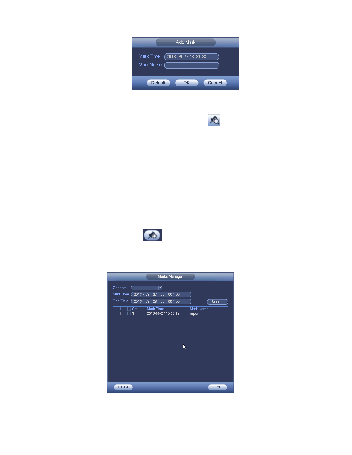
Add Mark
When system is playback, click Mark button , you can go to the following interface. See
Figure 4-39.
Page 60
253
Figure 4-39
Playback Mark
During 1-window playback mode, click mark file list button in Figure 4-36, you can go
to mark file list interface. Double click one mark file, you can begin playback from the mark
time.
Play before mark time
Here you can set to begin playback from previous N seconds of the mark time.
Note
Usually, system can playbacks previous N seconds record if there is such kind of record
file. Otherwise, system playbacks from the previous X seconds when there is such as kind
of record.
Mark Manager
Click the mark manager button on the Search interface (Figure 4-36); you can go
to Mark Manager interface. See Figure 4-40. System can manage all the record mark
information of current channel by default. You can view all mark information of current
channel by time.
Figure 4-40
Modify
Page 61
254
Double click one mark information item, you can see system pops up a dialogue box for
you to change mark information. You can only change mark name here.
Delete
Here you can check the mark information item you want to delete and then click Delete
button, you can remove one mark item. .
Note
After you go to the mark management interface, system needs to pause current
playback. System resume playback after you exit mark management interface.
If the mark file you want to playback has been removed, system begins playback from
the first file in the list.
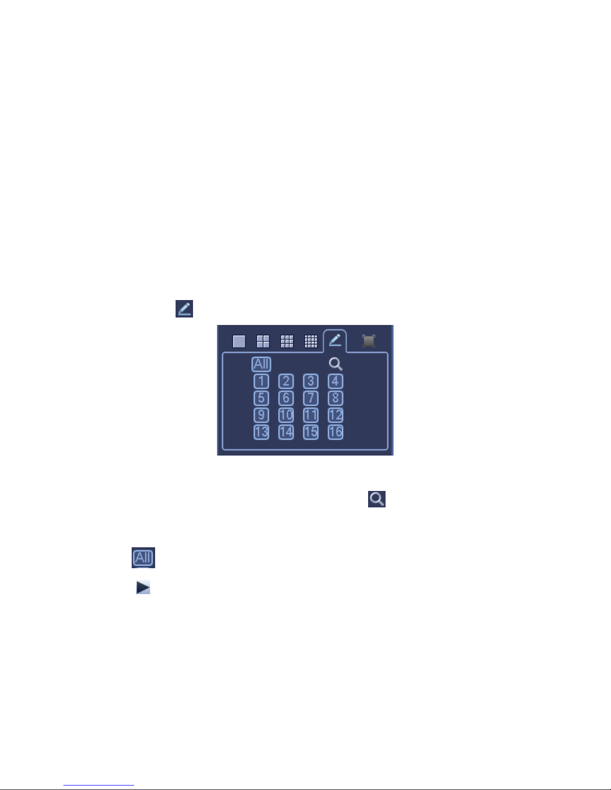
4.9.1.4 Customized Playback
You can select one or more channel(s) to playback at the same time.
From main menu->Search or you can right click mouse on the preview interface and then
select Search, you can go to Figure 4-36.
In pane 4, click , you can see the following interface. See Figure 4-41.
Figure 4-41
Now you can select one or more channel(s) and then click to search record(s).
System supports one or more channels. The window split mode can auto adjust according
to the channel amount. System max supports 16-split.
Click button to select all channels at the same time.
Click , system begins playback.
4.9.1.5 Splice Playback
For the large record file, you can use splice playback function to play the same file in
several sections at the same time. It is very convenient for you to find the video footages
you desire.
On the main menu, click Search button, or right click mouse and then select Search. You can
go to the Figure 4-36.
Page 62

255
On the right pane, check the box to enable splice playback function, and then set channel,
date, split mode. The splice playback interface is shown as below. Each section has a
small triangle; you can adjust it to set time. See Figure 4-42.
Figure 4-42
Note
Select split mode, so that the record can be spliced in several sections.
Select splice file.
Click Playback, system playbacks from the first of current date by default.
Click time bar, system playbacks from the time you click.
Click , you can select on the file list.
Note
The splice playback is for 1-window playback mode.
System supports 1/4/8/16-split mode. Slight different may be found here.
The min period of each section is 5 minutes. For the record is less than 20 minutes, if
you select 4-split mode (or more than 4-split mode), system can auto adjust so that
the each section period is 5 minutes. In this situation, some channel may have no
video.
4.9.2 Human Face Search
On the preview window, right click mouse and then select face search, or from the
main menu, click Face search, you can go to the following interface. See Figure 4-43.
Page 63

256
Figure 4-43
Please refer to the following sheet for detailed information.
SN
Name
Function
1
Display
pan
It is to display human face detection file list. The latest file is at the
top. \
Click Export, you can export the selected file to the USB device.
There are two types: image/record.
Image: Export the recognized human face image.
Record: Export the record file before and after 10 seconds
when the DVR recognizes the human face.
2
Playback
pane
Play the searched record file or image. Double click to playback in full
screen.
3
Search
pane
Set date, start time and end time, click Search button, you can view the
corresponding file list.
4.9.3 Backup
DVR support CD-RW, DVD burner, USB device backup, network download and
eSATA. Here we introduce USB, eSATA backup. You can refer to Chapter 7 Web
Client Operation for network download backup operation.
Click backup button, you can see an interface is shown as in Figure 4-44. Here is for
you to view devices information.
Page 64

257
You can view backup device name and its total space and free space. The device
includes CD-RW, DVD burner, USB device, flash disk, eSATA backup.
Figure 4-44
Select backup device and then set channel, file start time and end time.
Click add button, system begins search. All matched files are listed below. System
automatically calculates the capacity needed and remained. See Figure 4-45.
Figure 4-45
System only backup files with a √ before channel name. You can use Fn or cancel
Page 65

258
button to delete √ after file serial number.
Click Start button, system begins copy. At the same time, the backup button becomes
stop button. You can view the remaining time and process bar at the left bottom. See
Figure 4-46.
Figure 4-46
When the system completes backup, you can see a dialogue box prompting
successful backup.
File format: Click the file format; you can see there are two options: DAV/ASF.
The file name format usually is: Channel number+Record type+Time. In the file name,
the YDM format is Y+M+D+H+M+S. File extension name is .dav.
Tips:
During backup process, you can click ESC to exit current interface for other operation.
The system will not terminate backup process.
Note:
When you click stop button during the burning process, the stop function becomes
activated immediately. For example, if there are ten files, when you click stop system
just backup five files, system only save the previous 5 files in the device (But you can
view ten file names).
4.9.4 Shut Down
In Figure 4-35, select Shut Down, you can go to the following interface. See Figure 4-47.
There are three options: Shutdown/logout/reboot.
For the user who does not have the shut down right, please input corresponding password
to shut down.
Page 66

259
Figure 4-47
4.10 Information
4.10.1 System Info
Here is for you to view system information. There are total four items: HDD (hard disk
information), record, BPS (data stream statistics), version. See Figure 4-48.
Figure 4-48
4.10.1.1 HDD Information
Here is to list hard disk type, total space, free space, video start time and status. See
Figure 4-49.
SATA: 1-2 here means system max supports 2 HDDS. ○ means current HDD is
Page 67
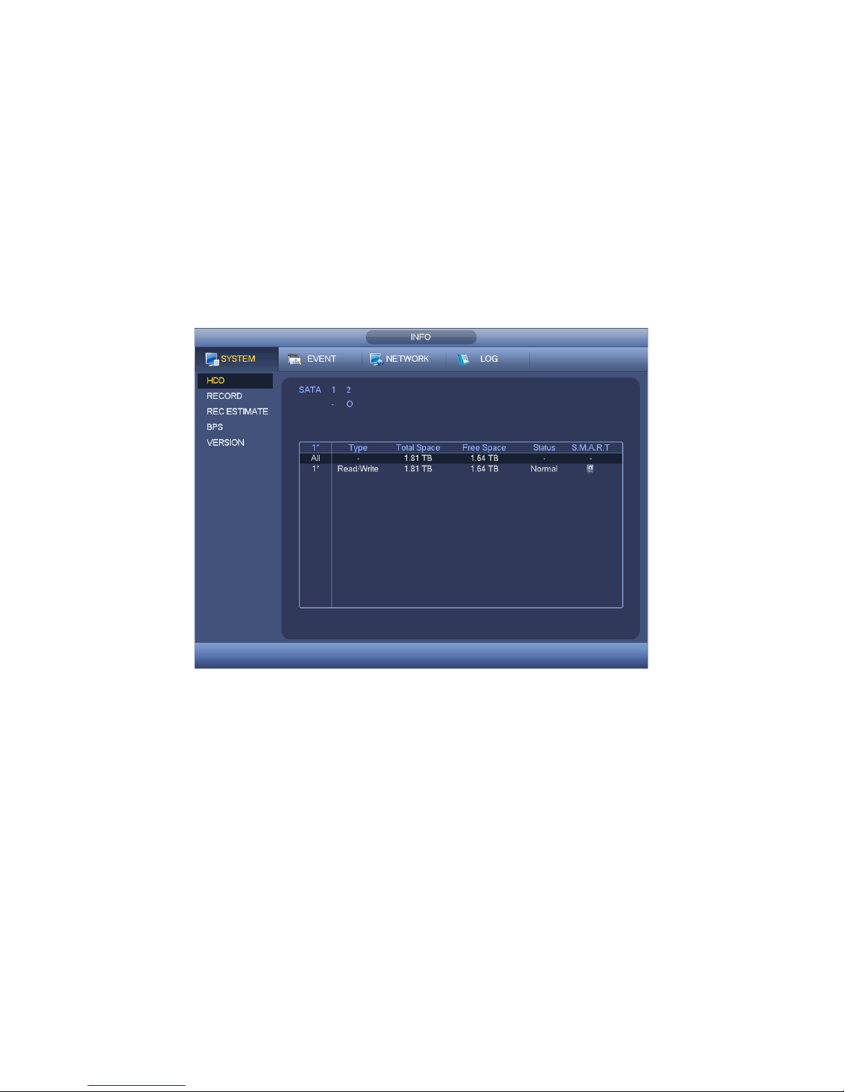
260
normal. X means there is error. - means there is no HDD. If disk is damaged, system
shows as “?”. Please remove the broken hard disk before you add a new one.
SN: You can view the HDD amount the device connected to. ﹡ means the second
HDD is current working HDD.
Type: The corresponding HDD properties.
Total space: The HDD total capacity.
Free space: The HDD free capacity.
Status: HDD can work properly or not.
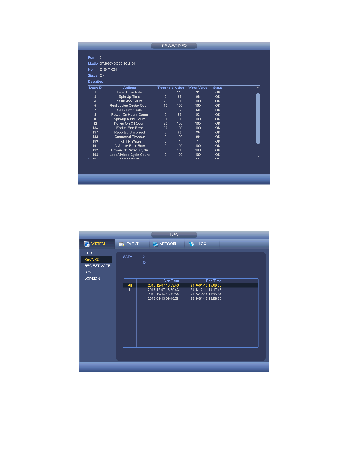
SMART: Display HDD information. See Figure 4-50.
Figure 4-49
Double click one HDD information; you can see the HDD SMART information. . See
Figure 4-50.
Page 68
261
Figure 4-50
4.10.1.2 Record Info
It is to view record start time and end time. See Figure 4-51.
Figure 4-51
4.10.1.3 Record Estimate
System can calculate the record time based on the HDD space, or you can input the
Page 69

262
record time you want to calculate the HDD space you need. See Figure 4-52.
Figure 4-52
Click after the channel name, system pops up Edit dialogue box. See Figure 4-53.
You can input resolution, frame rate, bit stream, record time of the corresponding channel,
system can calculate the record time based on the channel setup and HDD space.
Figure 4-53
Page 70

263
Calculate the record period based on the HDD space
Check the channel you want to record file.
Click Known Space and then click the button to set HDD. Click OK button.
Now you can see the record period (such as 5 days). See Figure 4-54.
Figure 4-54
Calculate the HDD space based on the record period
Check the channel you want to record file.
Input days(s) you want to records, system can auto calculate the HDD space needed
(such as 5.109TB). See Figure 4-55.
Page 71

264
Figure 4-55
4.10.1.4 BPS
Here is for you to view current video data stream (KB/s) and occupied hard disk storage
(MB/h). See Figure 4-56.
Figure 4-56
Page 72

265
4.10.1.5 Version
Here is for you to view some version information such as version number, built date, serial
number and etc. See Figure 4-57.
Figure 4-57
4.10.2 Event
It is to display device status and channel status. See Figure 4-58.
Figure 4-58
Page 73

266
4.10.3 Network
4.10.3.1 Online Users
Here is for you to manage online users. See Figure 4-59.
You can disconnect one user or block one user if you have proper system right. Max
disconnection setup is 65535 seconds.
System detects there is any newly added or deleted user in each five seconds and refresh
the list automatically.
Figure 4-59
4.10.3.2 Network Load
Network load is shown as in Figure 4-60. Here you can view the follow statistics of the
device network adapter.
Here you can view information of all connected network adapters. The connection status
is shown as offline if connection is disconnected. Click one network adapter, you can view
the flow statistics such as send rate and receive rate at the top panel.
Page 74

267
Figure 4-60
4.10.3.3 Network Test
Network test interface is shown as in Figure 4-61.
Destination IP: Please input valid IPV4 address or domain name.
Test: Click it to test the connection with the destination IP address. The test results
can display average delay and packet loss rate and you can also view the network
status as OK, bad, no connection and etc.
Network Sniffer backup: Please insert USB2.0 device and click the Refresh button,
you can view the device on the following column. You can use the dropdown list to
select peripheral device. Click Browse button to select the snap path. The steps here
are same as preview backup operation.
You can view all connected network adapter names (including Ethernet, PPPoE, WIFI,
and 3G), you can click the button on the right panel to begin Sniffer. Click the grey
stop button to stop. Please note system can not Sniffer several network adapters at the
same time.
After Sniffer began, you can exit to implement corresponding network operation such as
login WEB, monitor. Please go back to Sniffer interface to click stop Sniffer. System
can save the packets to the specified path. The file is named after “Network adapter
name+time”. You can use software such as Wireshark to open the packets on the PC for
the professional engineer to solve complicated problems.
Page 75

268
Figure 4-61
4.10.4 Log
4.10.4.1 Local Log
Here is for you to view system log file. System lists the following information. See Figure
4-62.
Log types include system operation, configuration operation, data management, alarm
event, record operation, account manager, log clear, file operation and etc. It optimized
reboot log. There are only three types: normal reboot, abnormal reboot and protection
reboot. 0x02、0x03、0x04 is included in the protection reboot type.
Start time/end time: Pleased select start time and end time, then click search button.
You can view the log files in a list. System max displays 100 logs in one page. It can
max save 1024 log files. Please use page up/down button on the interface or the front
panel to view more.
Backup: Please select a folder you want to save; you can click the backup button to
save the log files. After the backup, you can see there is a folder named Log_time on
the backup path. Double click the folder, you can see the log file
Details: Click the Details button or double click the log item, you can view the detailed
information. See Figure 4-63. Here you can use rolling bar to view information, or you
can use Page up/Page down to view other log information.
Page 76
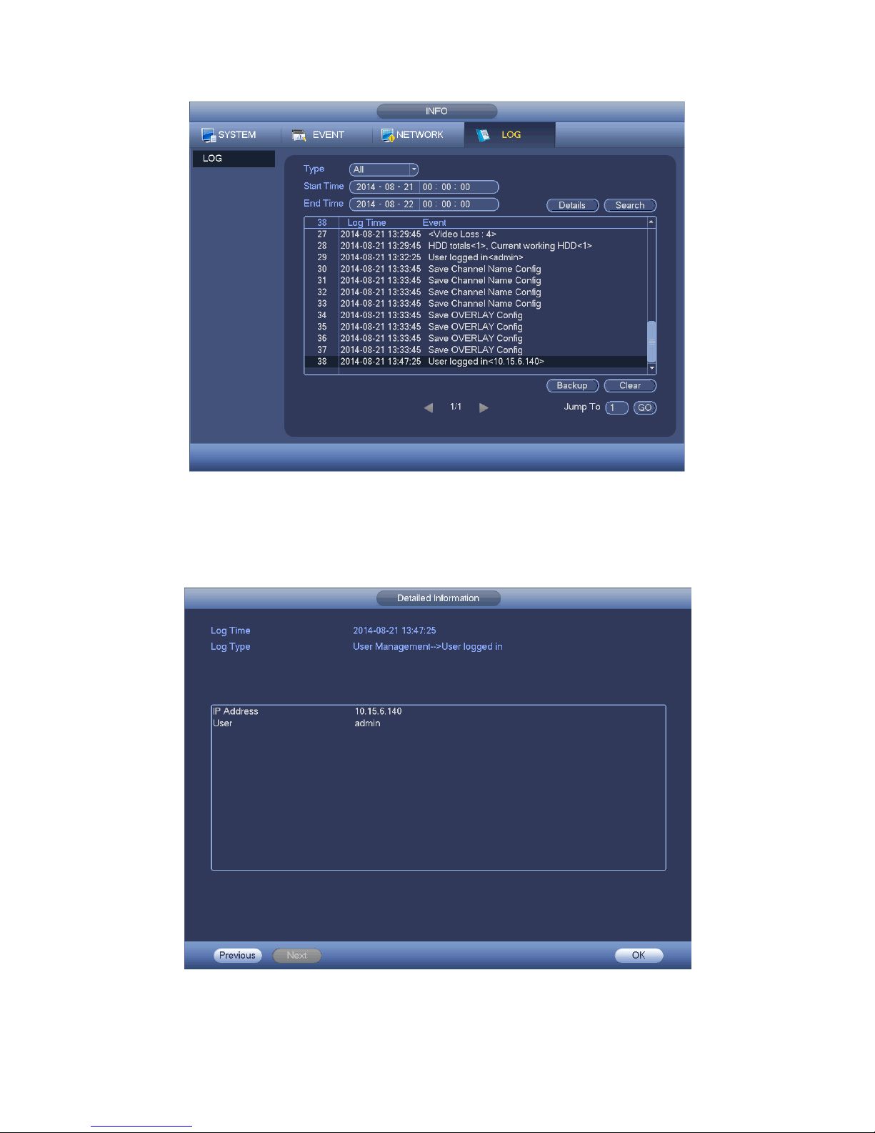
269
Figure 4-62
Select an item on the list and then click the Details button or double click the log item, you
can view the detailed information such as log time, log type, log user, IP address and etc.
See Figure 4-63.
Figure 4-63
Page 77

270
Note
If there is no HDD, system max supports 1024 logs.
If you have connected to the unformatted HDD, system max supports 5000 logs.
If you have connected to the formatted HDD, system max supports 500,000 logs.
System operation logs are saved in system memory. Other types of logs are saved in
the HDD. If there is no HDD, other types of logs are saved in the system memory too.
The logs are safe when you format the HDD. But the logs may become loss once you
removed the HDD.
4.11 Setting
4.11.1 Camera
4.11.1.1 Remote Device (For digital channel only)
4.11.1.1.1 Remote Device
In the main menu, from Camera ->Remote, you can go to an interface shown as in Figure
4-64. Here you can add/delete remote device and view its corresponding information.
IP search: Click it to search IP address. It includes device IP address, port, device
name, manufacturer, type. Use your mouse to click the item name, you can refresh
display order. Click IP address, system displays IP address from small to large. Click
IP address again, you can see icon, system displays IP address from large to small.
You can click other items to view information conveniently. For the network device
already added to the device, you can see there is a small icon “*” after the SN in case
there is repeatedly add operation.
Add: Click it to connect to the selected device and add it to the Added device list.
Support Batch add.
You can see the corresponding dialogue box if all digital-channel has connected to
the front-end.
System can not add new device if the device you want to add has the same IP and
TCP port as the device in the list.
Show filter: You can use it to display the specified devices from the added device.
Edit: Click button or double click a device in the list, you can change channel
setup.
Delete: Please select one device in the Added device list and then click to
remove.
Status: means connection is OK and means connection failed.
Delete;Select a device on the Added device list, click Delete button, system
disconnect device first and then remove its name from the list.
Manual add: Click it to add the IPC manually. The port number is 37777. The default
user name is admin and password is admin.
Page 78

271
Figure 4-64
Click the Manual Add button; you can go to the following interface. See Figure 4-65.
Channel number:The dropdown list here displays unconnected channel number. You can
go to Figure 4-64 to set remote channel connection.
Please note:
This series product supports the IPC from many popular manufactures such as Sony,
Hitachi, Axis, Samsung, Dynacolor, Arecont, Onvif and Dahua.
System default IP address is 192.168.0.0 if you do not input IP address. System will
not add current IP address.
You can not add two or more devices in the Manual Add interface (Figure 4-65). Click
OKbutton, system connects to the corresponding front-end device of current channel
on the interface.
Figure 4-65
Page 79

272
Show filer: It is to filter the searched device.
None: it is to display all searched devices.
IPC: It is to display all cameras.
DVR: It is to display all storage devices such as NVR, DVR.
Change IP:
Click , you can change the information such as IP address, subnet mask, and
default gateway, user name, password of the checked device. See Figure 4-66.
Figure 4-66
You can check several devices at the same time and then click the edit
button .See Figure 4-3. Please check Batch modify button and then input
start IP, end IP and default gateway.
Page 80
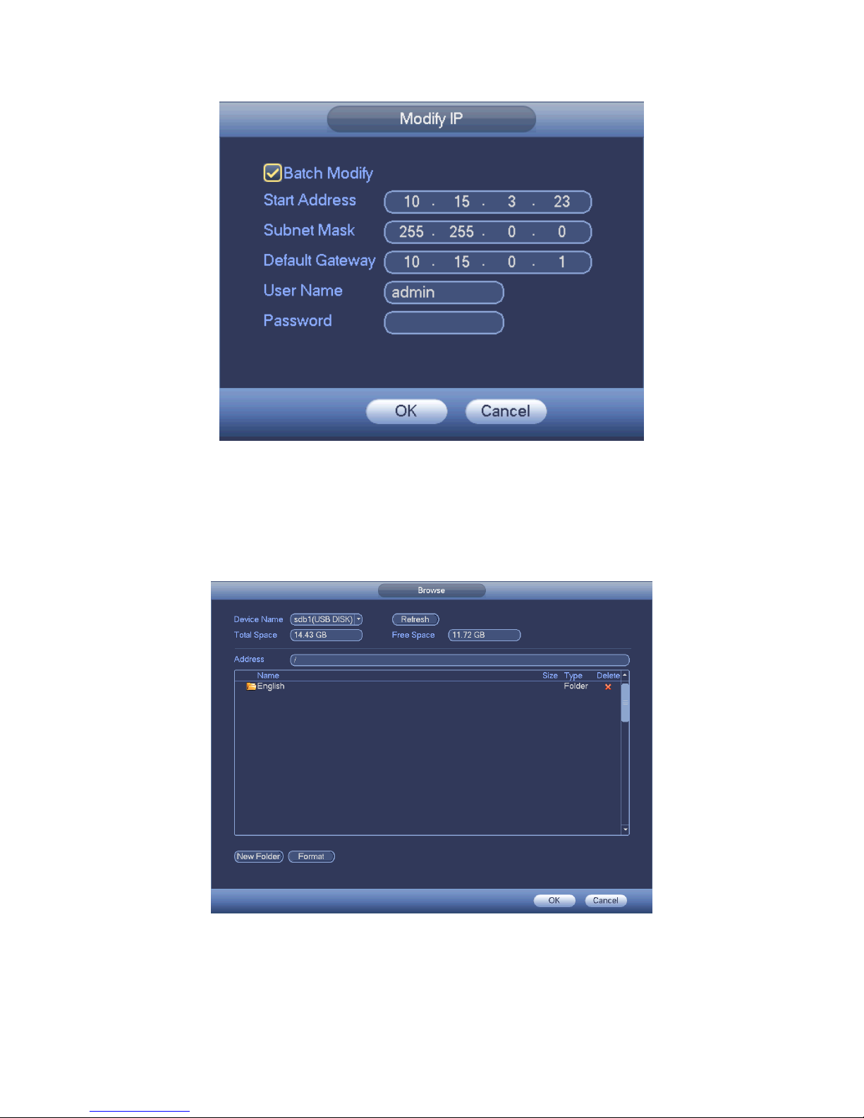
273
Figure 4-67
IP Export
System can export the Added device list to your local USB device.
Please insert the USB device and then click the Export button; you can see the following
interface. See Figure 4-68.
Figure 4-68
Select the directory and then click the OK button. System pops up a dialogue box to
remind you successfully exported. Please click OK button to exit.
Page 81
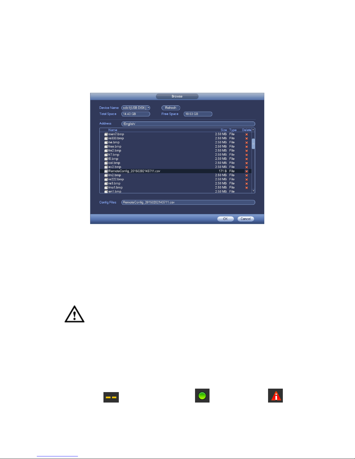
274
Note
The exported file extension name is .CVS. The file information includes IP address, port,
remote channel number, manufacturer, user name and password.
IP Import
Click Import button, you can see the following interface. See Figure 4-69.
Figure 4-69
Select the import file and then click the OK button. System pops up a dialogue box to
remind you successfully exported. Please click OK button to exit.
Note:
If the imported IP has conflicted with current added device, system pops up a dialogue
box to remind you. You have two options:
OK: Click OK button, system uses the imported setup to overlay current one.
Cancel: Click Cancel button, system adds the new IP setup.
Important
You can edit the exported .CVS file. Do not change the file format; otherwise it
may result in import failure.
Does not support customized protocol import and export.
The import and export device shall have the same language format.
4.11.1.1.2 Channel Status
Here you can view the IPC status of the corresponding channel such as motion detect,
video loss, tampering, alarm and etc. See Figure 4-70.
IPC status: : Front-end does not support. : Front-end supports. :
There is alarm event from current front-end.
Page 82

275
Connection status: : Connection succeeded. : Connection failed.
Refresh: Click it to get latest front-end channel status.
Figure 4-70
4.11.1.1.3 Firmware
It is to view channel, IP address, manufacturer, type, system version, SN, video input,
audio input, and etc. See Figure 4-71.
Figure 4-71
Page 83

276
4.11.1.2 Image
For analog channel, the camera interface is shown as in Figure 4-72. For digital
channel, the camera interface is shown as in Figure 4-73 .
Channel: Select a channel from the dropdown list.
Cable type: It is to set the cable type of the corresponding analog channel. When the
setup here matches the actual cable you are using, you can get the best image effect.
The default setup is COAXIAL.
COAXIAL: When the corresponding channel is using coaxial cable, please select
COAXIAL.
UTP: When the corresponding channel is using UTP cable, please select UTP.
Usually we recommend 10Ohm UTP cable.
Saturation: It is to adjust monitor window saturation. The value ranges from 0 to 100.
The default value is 50. The larger the number, the strong the color is. This value has
no effect on the general brightness of the whole video. The video color may become
too strong if the value is too high. For the grey part of the video, the distortion may
occur if the white balance is not accurate. Please note the video may not be
attractive if the value is too low. The recommended value ranges from 40 to 60.
Brightness: It is to adjust monitor window bright. The value ranges from 0 to 100. The
default value is 50. The larger the number is, the bright the video is. When you input
the value here, the bright section and the dark section of the video will be adjusted
accordingly. You can use this function when the whole video is too dark or too bright.
Please note the video may become hazy if the value is too high. The recommended
value ranges from 40 to 60.
Contrast: It is to adjust monitor window contrast. The value ranges from 0 to 100. The
default value is 50. The larger the number is, the higher the contrast is. You can use
this function when the whole video bright is OK but the contrast is not proper. Please
note the video may become hazy if the value is too low. If this value is too high, the
dark section may lack brightness while the bright section may over exposure .The
recommended value ranges from 40 to 60.
Sharpness: The value here is to adjust the edge of the video. The value ranges from 0
to 100. The larger the value is, the clear the edge is and vice versa. Please note there
is noise if the value here is too high. The default value is 50 and the recommended
value ranges from 40 to 60.
Mirror: It is to switch video up and bottom limit. This function is disabled by default.
Flip: It is to switch video left and right limit. This function is disabled by default.
BLC:It includes several options: BLC/WDR/HLC/OFF.
BLC: The device auto exposures according to the environments situation so that the
darkest area of the video is cleared
WDR: For the WDR scene, this function can lower the high bright section and
enhance the brightness of the low bright section. So that you can view these two
sections clearly at the same time. The value ranges from 1 to 100. When you switch
the camera from no-WDR mode to the WDR mode, system may lose several seconds
record video.
Page 84

277
HLC: After you enabled HLC function, the device can lower the brightness of the
brightest section according to the HLC control level. It can reduce the area of the halo
and lower the brightness of the whole video.
OFF: It is to disable the BLC function. Please note this function is disabled by default.
Profile: It is to set the white balance mode. It has effect on the general hue of the
video. This function is on by default. You can select the different scene mode such as
auto, sunny, cloudy, home, office, night, disable and etc to adjust the video to the best
quality.
Auto: The auto white balance is on. System can auto compensate the color
temperature to make sure the vide color is proper.
Sunny: The threshold of the white balance is in the sunny mode.
Night: The threshold of the white balance is in the night mode.
Customized: You can set the gain of the red/blue channel. The value reneges from 0
to 100.
Day/night. It is to set device color and the B/W mode switch. The default setup is auto.
Color: Device outputs the color video.
Auto: Device auto select to output the color or the B/W video according to the device
feature (The general bright of the video or there is IR light or not.)
B/W: The device outputs the black and white video.
Sensor: It is to set when there is peripheral connected IR light.
Image enhancement: It is to enhance video quality. The larger the value is, the clearer
the video is. But the noise may become large too.
2D NR: It is to process the noise of the single image. The video may become soft after
process. The larger the value is, the better the effect is.
3D NR: it is to process the multiple-frame (at least two frames). It is to use the frame
information between the following two frames to reduce noise. The larger the value is,
the better the effect is.
Page 85
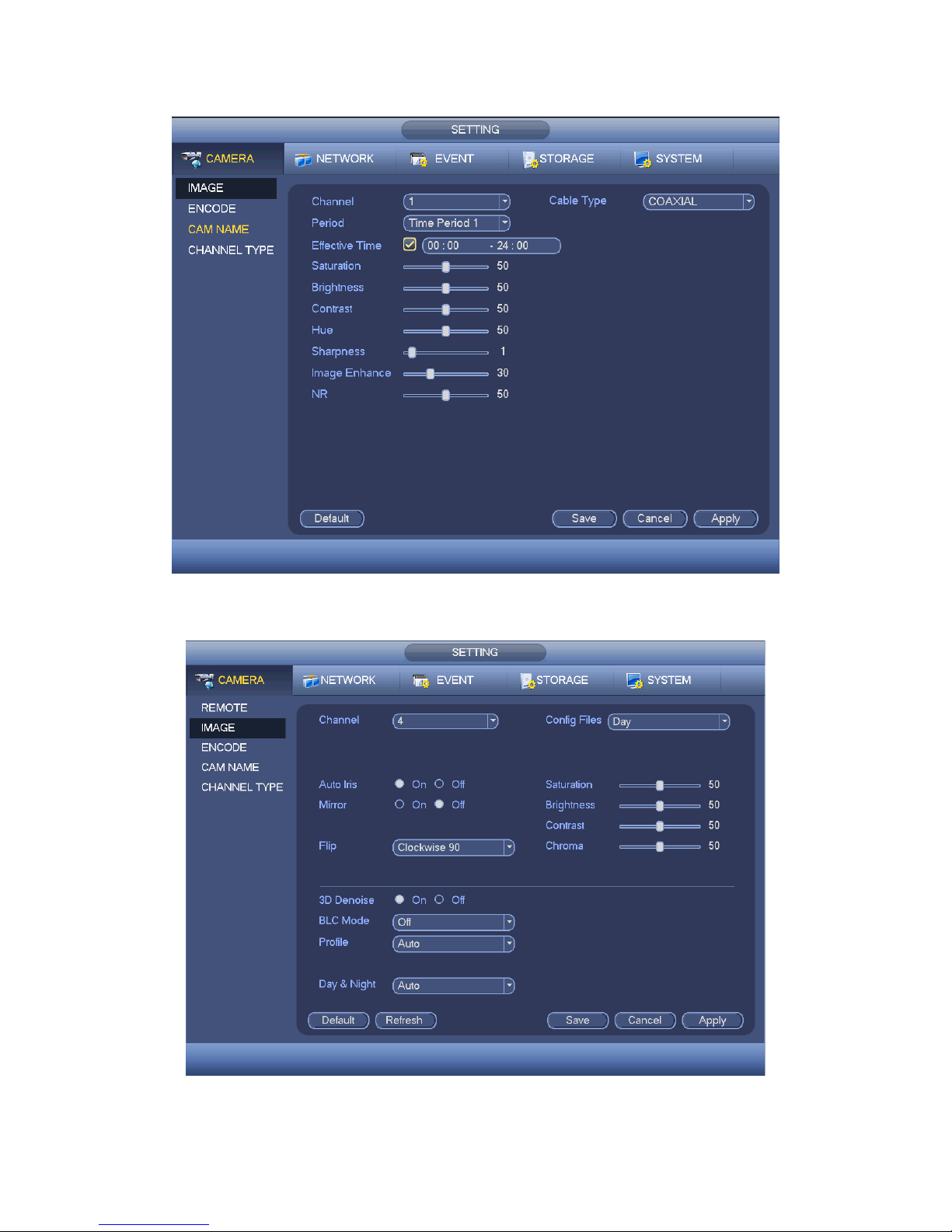
278
Figure 4-72
Figure 4-73
Page 86

279
4.11.1.3 Encode
It is to set video bit stream, picture bit stream, video overlay parameter and etc.
4.11.1.3.1 Video
Video setting includes the following items. See Figure 4-74.
Channel: Select the channel you want.
SVC: SVC is so called scaled video coding. Check the box to enable this function.
During the network transmission process, system discards unimportant frames when
the bandwidth is not sufficient or the decode capability is low. It is to guarantee video
quality and transmission fluency.
Type: Please select from the dropdown list. There are three options: regular/motion
detect/alarm. You can set the various encode parameters for different record types.
Compression: System supports H.264H, H.264, H.264B, and MJPEG.
H.264H: It is the High Profile compression algorithm. It has the high encode
compression rate. It can achieve high quality encode at low bit stream. Usually
we recommend this type.
H.264 is the general compression algorithm.
H.264B is the Baseline algorithm. Its compression rate is low. For the same video
quality, it has high bit stream requirements.
Smart codec: Select Start from the dropdown list to enable smart codec function. The
DVR can auto reduce the video bit stream of the non-important surveillance object to
save the storage space.
Resolution: For analog channel, system supports various resolutions, you can select
from the dropdown list. Please note the option may vary due to different series. For
digital channel, the resolution here refers to the capability of the network camera.
Frame rate: It ranges from 1f/s to 25f/s in NTSC mode and 1f/s to 30f/s in PAL mode.
Bit rate type: System supports two types: CBR and VBR. In VBR mode, you can set
video quality.
Quality: There are six levels ranging from 1 to 6. The sixth level has the highest image
quality.
Video/audio: You can enable or disable the video/audio.
Audio format: Please select from the dropdown list. There are three options:
G711a/G711u/PCM.
Audio source: Please select from the dropdown list. There are two options:
local/HDCVI. For local mode, the audio signal is from the Audio In port. For HDCVI
mode, the audio signal is from the coaxial cable of the camera.
Page 87
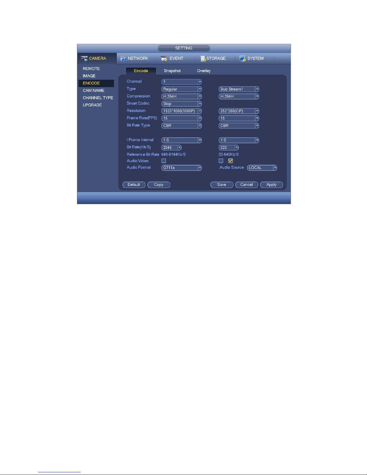
280
Figure 4-74
4.11.1.3.2 Snapshot
Here you can set snapshot mode, picture size, quality and frequency. See Figure 4-75.
Snapshot mode: There are two modes: regular and trigger. If you set timing mode,
you need to set snapshot frequency. If you set trigger snapshot, you need to set
snapshot activation operation.
Image size: Here you can set snapshot picture size.
Image quality: Here you can set snapshot quality. The value ranges from 1 to 6.
Interval: It is for you to set timing (schedule) snapshot interval.
Page 88

281
Figure 4-75
4.11.1.3.3 Overlay
Overlay interface is shown as in Figure 4-76.
Cover area: Here is for you to set cover area. You can drag you mouse to set proper
section size. In one channel video, system max supports 4 zones in one channel.
Preview/monitor: privacy mask has two types. Preview and Monitor. Preview means
the privacy mask zone can not be viewed by user when system is in preview status.
Monitor means the privacy mask zone can not be view by the user when system is in
monitor status.
Time display: You can select system displays time or not when you playback. Please
click set button and then drag the title to the corresponding position in the screen.
Channel display: You can select system displays channel number or not when you
playback. Please click set button and then drag the title to the corresponding position
in the screen.
Copy:After you complete the setup, you can click Copy button to copy current setup
to other channel(s). You can see an interface is shown as in Figure 4-77. You can see
current channel number is grey. Please check the number to select the channel or you
can check the box ALL. Please click the OK button in Figure 4-77 and Figure 4-76
respectively to complete the setup.
Please highlight icon to select the corresponding function.
Page 89

282
Figure 4-76
Figure 4-77
4.11.1.3.4 Channel Name
It is to modify channel name. It max supports 31-character. See Figure 4-78.
Please note for digital channel, you can only modify the channel name of the connected
network camera.
Page 90

283
Figure 4-78
4.11.1.3.5 Channel Type
It is to set channel type. Each channel supports analog standard definition
connections/analog HD connection/network camera connection (Slight function difference
may be found). For the IP channel, you need to set from the last channel. Please note
DVR needs to restart to activate new setup.
The interface is shown as in Figure 4-79.
Page 91

284
Figure 4-79
Important notice about XVR series product:
Nowadays, there are mainly two analog signal types on today market: analog
standard definition (CVBS) and analog HD (CVI, AHD or Other). For XVR series
product, each channel supports all types of signal connection (analog signal/IP
signal). For analog signal connection, the default setup is AUTO, that is to say, no
matter what analog signal (CVBS, CVI, AHD or other analog HD signal) connected;
the XVR can automatically recognize the signal and display the proper image. There
is no need to set manually.
If the auto recognition error occurred, XVR series product supports manual setup too.
The manual setup featuring high recognition speed and usually there is no error. For
example, in Figure 4-80, you can set channel 1 to connect to CVI camera, channel 2
to connect to AHD camera, channel 3 to connect to CVBS camera.
Figure 4-80
Important
Add/cancel IP CAM function is for some 4/8/16-channel series product only.
Add IP CAM: Click it; you can add corresponding X IP channels. Here X refers to the
product channel amount such as 4/8/16. System needs to restart to activate new
setup. See Figure 4-81.
Page 92
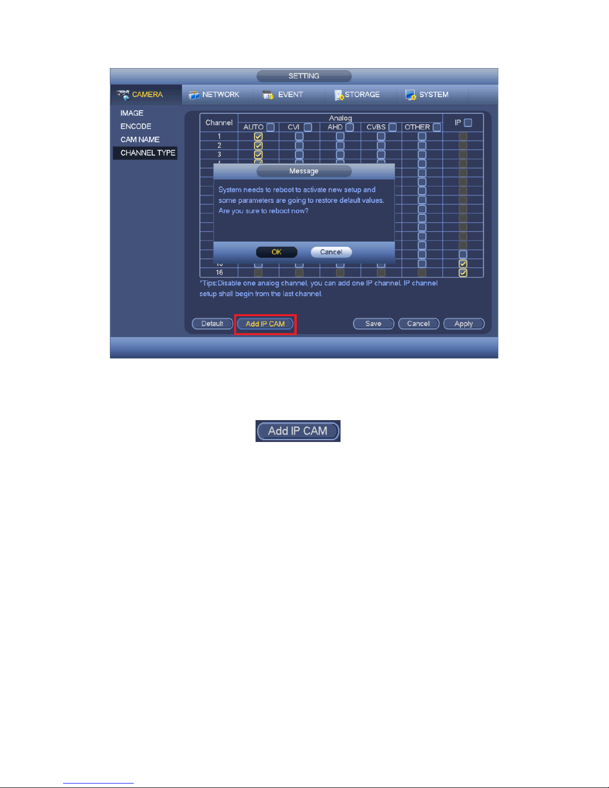
285
Figure 4-81
For example, there is a 4-channel analog device, after the A/D switch, it can max supports
4 analog channels and 4 IP channels. Once it has become the 3+1 mode (3 analog
channels+1 IP channel), you click button, system becomes 3+5 mode
(3 analog channels+5 IP channel).
Cancel IP CAM: Click it, you can cancel IP channel. System needs to restart to
restore original status.
Page 93

286
Figure 4-82
4.11.1.3.1 Upgrade
Important
XVR series product does not support upgrade function via coaxible cable. That is to
say, you cannot use this interface to upgrade the connected CVI camera if you are
using XVR.
It is to update the online camera.
From main menu->setting->camera->remote upgrade, the interface is shown as below.
See Figure 4-83.
Click Browse button and then select the upgrade file. Then select a channel (or you can
select device type filter to select several devices at the same time.)
Click Start upgrade button to update. You can see the corresponding dialogue once the
upgrade is finish.
Page 94

287
Figure 4-83
4.11.2 Network
4.11.2.1 TCP/IP
The single network adapter interface is shown as in Figure 4-84 and the dual network
adapters interface is shown as in Figure 4-85
Network Mode : Includes multiple access, fault tolerance, and load balancing
Multiple-address mode: eth0 and eth1 operate separately. You can use the
services such as HTTP, RTP service via etho0 or the eth1. Usually you need to
set one default card (default setup is etho) to request the auto network service
form the device-end such as DHCP, email, FTP and etc. In multiple-address
mode, system network status is shown as offline once one card is offline.
Network fault-tolerance: In this mode, device uses bond0 to communicate with
the external devices. You can focus on one host IP address. At the same time,
you need to set one master card. Usually there is only one running card (master
card).System can enable alternate card when the master card is malfunction. The
system is shown as offline once these two cards are both offline. Please note
these two cards shall be in the same LAN.
Load balance: In this mode, device uses bond0 to communicate with the external
device. The eth0 and eth1 are both working now and bearing the network load.
Their network load are general the same. The system is shown as offline once
these two cards are both offline. Please note these two cards shall be in the same
LAN.
Default Network Card: Please select eth0/eth1/bond0(optional) after enable
multiple-access function
Page 95

288
Main Network Card: Please select eth0/eth1 (optional).after enable multiple
access function.
Note: Some series support the above three configurations and supports
functions as multiple-access, fault-tolerance and load balancing.
IP Version: There are two options: IPv4 and IPv6. Right now, system supports these two
IP address format and you can access via them.
MAC address: The host in the LAN can get a unique MAC address. It is for you to access
in the LAN. It is read-only.
IP address: Here you can use up/down button () or input the corresponding
number to input IP address. Then you can set the corresponding subnet mask the
default gateway.
Default gateway: Here you can input the default gateway. Please note system needs
to check the validity of all IPv6 addresses. The IP address and the default gateway
shall be in the same IP section. That is to say, the specified length of the subnet prefix
shall have the same string.
DHCP: It is to auto search IP. When enable DHCP function, you can not modify
IP/Subnet mask /Gateway. These values are from DHCP function. If you have not
enabled DHCP function, IP/Subnet mask/Gateway display as zero. You need to
disable DHCP function to view current IP information. Besides, when PPPoE is
operating, you can not modify IP/Subnet mask /Gateway.
MTU: It is to set MTU value of the network adapter. The value ranges from 1280-7200
bytes. The default setup is 1500 bytes. Please note MTU modification may result in
network adapter reboot and network becomes off. That is to say, MTU modification
can affect current network service. System may pop up dialog box for you to confirm
setup when you want to change MTU setup. Click OK button to confirm current reboot,
or you can click Cancel button to terminate current modification. Before the
modification, you can check the MTU of the gateway; the MTU of the DVR shall be the
same as or is lower than the MTU of the gateway. In this way, you can reduce packets
and enhance network transmission efficiency.
The following MTU value is for reference only.
1500: Ethernet information packet max value and it is also the default value. It is
the typical setup when there is no PPPoE or VPN. It is the default setup of some
router, switch or the network adapter.
1492: Recommend value for PPPoE.
1468: Recommend value for DHCP.
Preferred DNS server: DNS server IP address.
Alternate DNS server: DNS server alternate address.
Transfer mode: Here you can select the priority between fluency/video qualities.
LAN download: System can process the downloaded data first if you enable this
function. The download speed is 1.5X or 2.0X of the normal speed.
LAN download: System can process the downloaded data first if you enable this
function. The download speed is 1.5X or 2.0X of the normal speed.
After completing all the setups please click save button, system goes back to the previous
menu.
Page 96
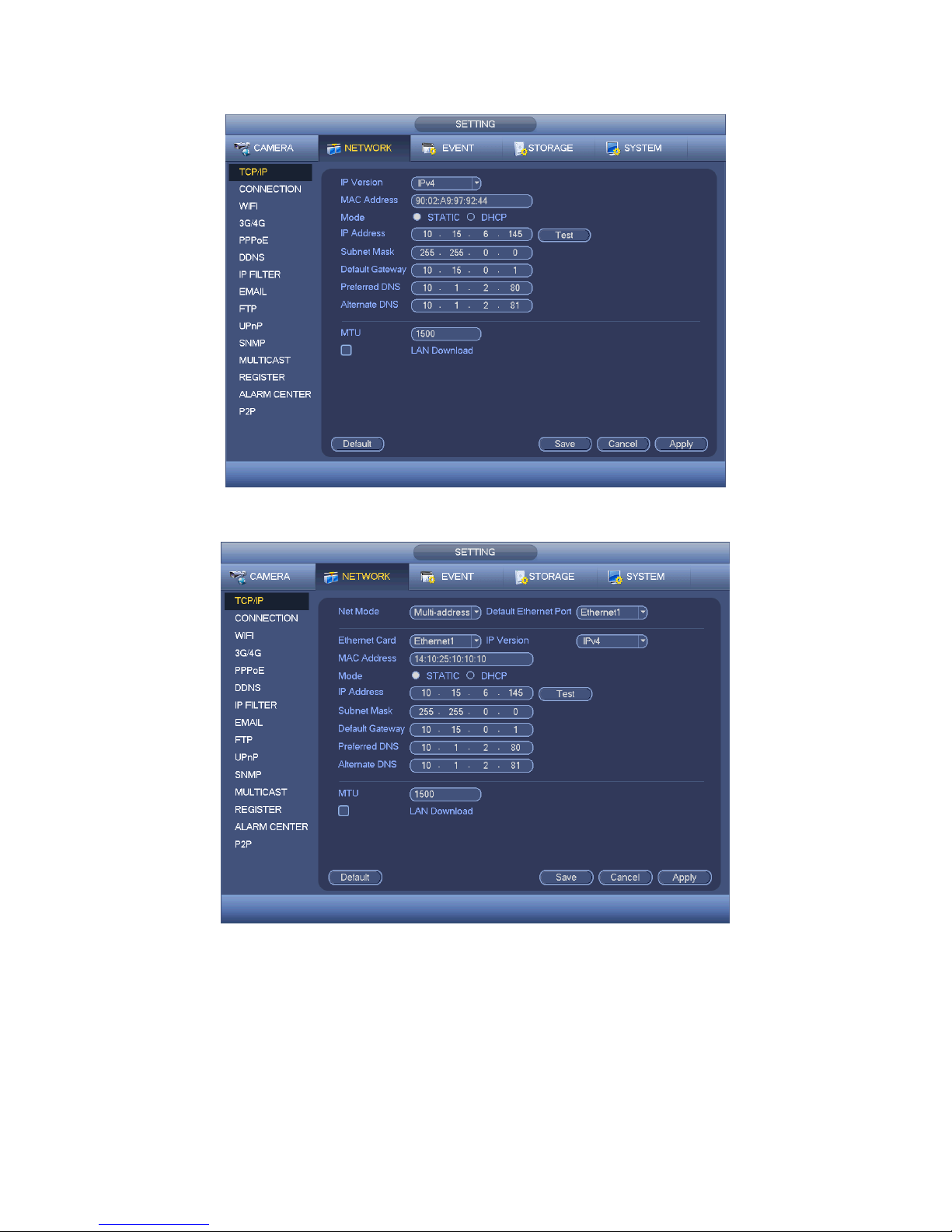
289
Figure 4-84
Figure 4-85
4.11.2.2 Connection
The connection setup interface is shown as in Figure 4-86.
Max connection: system support maximal 128 users. 0 means there is no connection
limit.
TCP port: Default value is 37777.
UDP port: Default value is 37778.
Page 97
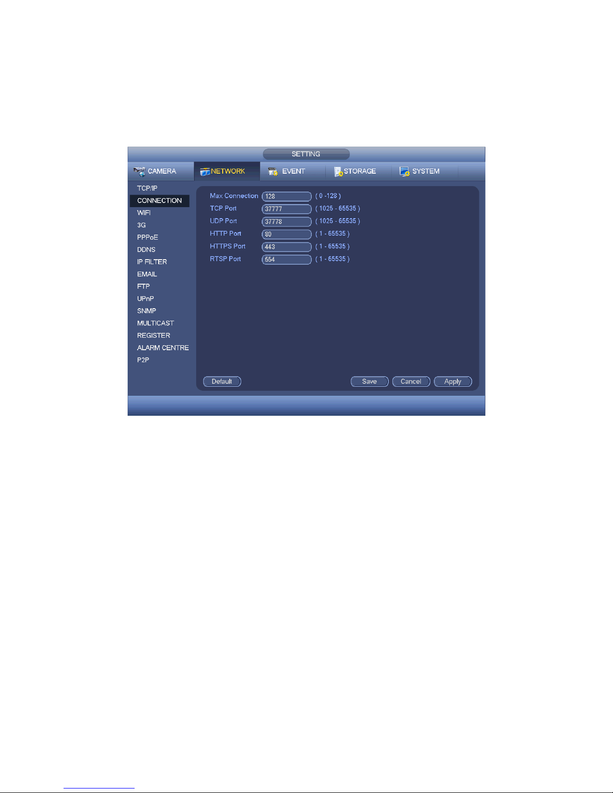
290
HTTP port: Default value is 80.
HTTPS port: Default value is 443.
RTSP port: Default value is 554.
Important: System needs to reboot after you changed and saved any setup of the
above four ports. Please make sure the port values here do not conflict.
Figure 4-86
4.11.2.3 WIFI
The WIFI interface is shown as below. See Figure 4-87.
Auto connect WIFI: Check the box here, system automatically connects to the
previous WIFI hotspot.
Refresh: You can click it to search the hotspot list again. It can automatically add the
information such as the password if you have set it before.
Disconnect: Here you can click it to turn off the connection.
Connect: Here you can click it to connect to the hotspot. System needs to turn off
current connection and then connect to a new hotspot if there is connection of you
selected one.
Page 98
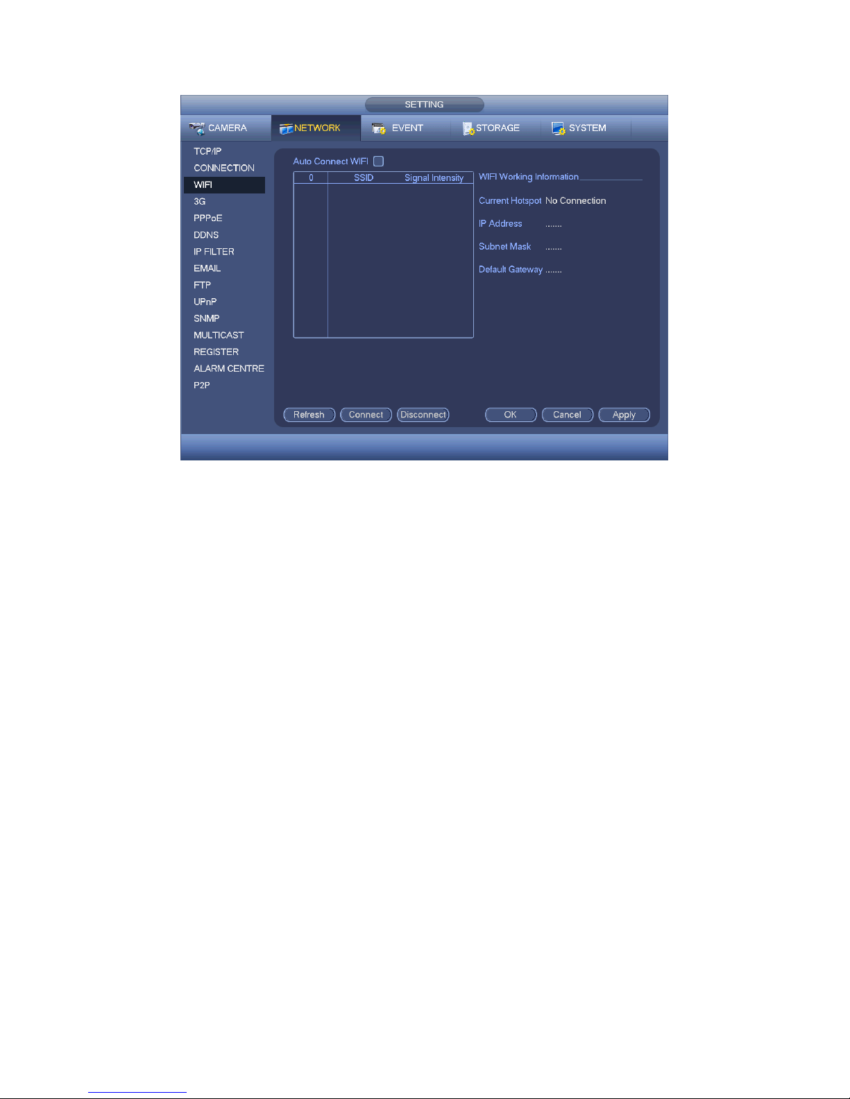
291
Figure 4-87
WIFI working status: Here you can view current connection status.
Please note:
After successful connection, you can see WIFI connection icon at the top right corner
of the preview interface.
When the hotspot verification type is WEP, system displays as AUTO since the device
can not detect its encryption type.
System does not support verification type WPA and WPA2. The display may become
abnormal for the verification type and encryption type.
After device successfully connected to the WIFI, you can view the hotspot name, IP
address, subnet mask, default gateway and etc.
4.11.2.4 3G
3G setup interface is shown as below. See Figure 4-88.
Please refer to the following contents for the parameter information.
Pane 1: Display 3G signal intensity after you enabled 3G function.
Pane 2: Display 3G module configuration information after you enabled 3G function.
Pane 3: Display 3G module status information after you enabled 3G function.
It is to display current wireless network signal intensity such as EVDO, CDMA1x, WCDMA,
WCDMA, EDGE and etc.
3G module: It is to display current wireless network adapter name.
3G Enable/Disable: Check the box here to enable 3G module.
Network type: There are various network types for different 3G network modules. You
can select according to your requirements.
Page 99
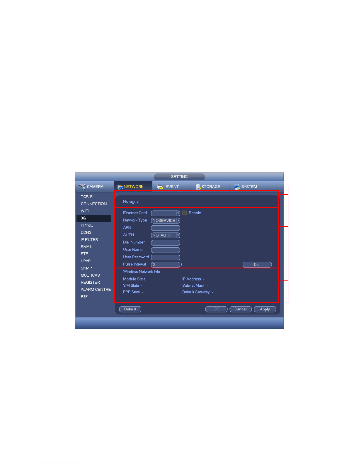
292
APN: It is the wireless connection server. It is to set you access the wireless network
via which method.
AUTH: It is the authentication mode. It supports PAP/CHAP.
Dial number: Please input 3G network dialup number you got from your ISP.
User name: It is the user name for you to login the 3G network.
Password: It is the password for you to login the 3G network.
Pulse interval: You can set dialup duration. Once you disable the extra stream, the
connection time begins. For example, if you input 5 seconds here, then 3G network
connection period is 5 seconds. The device automatically disconnect when time is up.
If there is no extra stream, 3G network connection is valid all the time. If the alive
time is 0, then the 3G network connection is valid all the time.
Dial: Here you can enable or disable 3G network connection/disconnection manually.
3G wireless network: Here is to display wireless network status, SIM card status, dial
status. If the 3G connection is OK, then you can see the device IP address the
wireless network automatically allocates.
Figure 4-88
4.11.2.5 PPPoE
PPPoE interface is shown as in Figure 4-89.
Input “PPPoE name” and “PPPoE password” you get from your ISP (Internet service
provider).
Click save button, you need to restart to activate your configuration.
After rebooting, DVR will connect to internet automatically. The IP in the PPPoE is the
DVR dynamic value. You can access this IP to visit the unit.
1
2
3
Page 100

293
Figure 4-89
4.11.2.6 DDNS Setup
DDNS setup interface is shown as in Figure 4-90.
You need a PC of fixed IP in the internet and there is the DDNS software running in this
PC. In other words, this PC is a DNS (domain name server).
In network DDNS, please select DDNS type and highlight enable item. Them please input
your PPPoE name you get from you IPS and server IP (PC with DDNS). Click save button
and then reboot system.
Click save button, system prompts for rebooting to get all setup activated.
After rebooting, open IE and input as below:
http://(DDNS server IP)/(virtual directory name)/webtest.htm
e.g.: http://10.6.2.85/DVR _DDNS/webtest.htm.)
Now you can open DDNSServer web search page.
 Loading...