

TechPlus ComfortAire Service Supplement Manual

TechPlusTechPlus
SERVICE SUPPLEMENT
Comfort AireComfort Aire
AIR CONDITIONING SYSTEMS

L
Technical Communications
TechPlus Supplement
for
Comfort Aire
School Bus Air Conditioning Systems
on
BLue BIrd All American Forward Engine
Blue Bird All American Rear Engine
Blue Bird Vision
Blue Bird MicroBird

TechPlus
l
s e r v i c e s u p p l e m e n t
© 2006, 2007 Blue Bird Corporation. All rights reserved.
In the event of any conflict between the requirements of this publication and any applicable legal requirement, the legal require-
ment prevails. Technical requirements that exceed the legal requirements are not considered to conflict.
The material presented in this manual is accurate at the time of publication. Blue Bird Corporation continually endeavors to im-
prove its product and reserves the right to change without notice.
2

c c 8 0
I N T R O D U C T I O N
About Blue Bird TechPlus Supplements
School buses are built with a wide array of equipment features which vary not only
according to manufacturer’s models, but also according to state governmental regu-
lations and customer-specifications. Such features often apply to a relative few buses
sold within a particular model category; and some features involve complex systems
or components which require appropriately detailed service information.
For these reasons, including full documentation of every available feature in the
printed version of the primary Service Manual for a particular bus model is not al-
ways practical. Blue Bird’s Technical Communications group prepares and publishes
TechPlus Supplements for such situations.
Intended Readership
This TechPlus Supplement is written for fully qualified professional Service Techni-
cians in specific areas performing maintenance and repair of Blue Bird buses. It is
assumed that the user of this publication is properly equipped and abides by all ap-
propriate safety precautions and procedures.
Content Sources
Blue Bird’s Technical Communications group is a full-time staff within the Customer
Services division at the home plant in Fort Valley, Georgia, where its Tech Publishers
have full access to Blue Bird’s assembly lines and Engineering department.
Blue Bird incorporates into its buses top quality components from leading manu-
facturers in the heavy automotive industry. The Engineering staffs of these compo-
nent vendors are the real experts on their specific components. These manufacturing
partners often provide their own publications to Blue Bird Technical Communica-
tions for republishing as appendixes within Blue Bird’s Service Manuals for direct-
from-the-source, component-specific information.
Therefore, content in TechPlus publications may be written by Blue Bird’s own
Technical Publishers; or may be provided by Blue Bird’s manufacturing partners; or
may be comprised of both Blue-Bird authored and vendor-authored material.
The bulk of this TechPlus Supplement is prepared by Blue Bird’s vendor, Mobile
Climate Controls, which builds the Comfort Aire air conditioner units to Blue Bird
specifications.
Subject of This Supplement
This Service Supplement is prepared to provide additional information to qualified
school bus Service Technicians regarding the Comfort Aire air conditioning systems
installed as an option on some Blue Bird school buses.
Applicable Bus Models
Comfort AIre air conditioning systems are installed on these Blue Bird models:
Blue Bird All American Forward Engine
Blue Bird All American Rear Engine
Blue Bird MicroBird
Blue Bird Vision

TechPlus
l
s e r v i c e s u p p l e m e n t
4
Blue Bird Comfort Aire
Maintenance Manual
For
All American (A3FE/RE),
Conventional Vision (BBCV) & Micro
Bird Body Types
(REVISION.003)
c c 8 0
C O M F O R T A I R E A / C S Y S T E M S
Comfort AIrE
1
APPENDIX

TechPlus
Important Information about Using This Manual
Please note that this manual is included with all Blue Bird
buses equipped with the Blue Bird factory installed and
supported Comfort Aire, air conditioning system.
Therefore the user will find the manual body to provide
excellent safety practices, driver instructions and simple
trouble shooting, technician instructions and detailed trouble
shooting/replacement procedures. As well as recommended
regular maintenance checks for both the driver and
technician.
The manual body shows detailed three dimensional models
of only the large 55,000 BTU/hr evaporators and the dual
core large bus condenser. All other evaporator and
condenser configurations share the same basic components.
The appendix pages at the end will contain an assembled
view drawing with basic data, exploded view drawings and
part number lists for each evaporator and condenser
configuration offered.
Please refer to the MCC part number on the label attached
to the outside surface of each component’s metal casing to
determine which unit you are working with.
The appendix also contains large wiring schematics for each
bus configuration.
l
s e r v i c e s u p p l e m e n t
c c 8 0
6
APPENDIX
1

c O m F O r t A i r e A / c s Y s t e m sc c 8 0
Safety Precautions / 10
General Practices / 10
Refrigerant / 11
First Aid / 11
Refrigeration Oil / 11
First Aid / 11
Electrical Hazards / 12
High Voltage / 12
Precautions / 12
First Aid / 12
Low Voltage / 13
Comfort Aire Specifications / 14
General / 14
R-134a Refrigeration System Charges and Set-points / 14
A3RE/FE & BBCV with TM-21’s Electrical System / 15
Micro Bird Electrical System / 15
Maintenance Inspection Schedule / 16
General Unit Description / 17
General Unit Operation / 18
Cooling / 18
Evaporator Coil Defrost / 18
Unit Features / 18
Protection Features / 18
General System Component Details / 19
Stacked Skirt Mounted Condenser Conguration / 19
Stacked Skirt Mounted Condenser Exploded View / 20
55,000 Bth/hr Free Blow Evaporator Conguration / 21
55,000 Btu/hr Free Blow Evaporator Exploded View / 22
Typical TM-21 Compressor / 23
Manual Control Panel / 23
High Pressure Binary Switch / 24
Electronic Thermostat / 24
Driver Instructions and Information / 25
Starting the Unit / 25
Bi Monthly Post Trip Checks / 26
Regular Maintenance by Driver / 26
Basic Trouble Shooting for Driver / 26
1
APPENDIX
7

TechPlus
l
s e r v i c e s u p p l e m e n t
Technician Instructions and Information / 28
Charging the Air Conditioning System / 28
Checking the Refrigerant Charge / 29
Checking the Compressor Oil Charge / 29
High Pressure Binary Switch / 29
Clean Up Procedures / 31
Part Replacement Procedures / 33
Compressor / 33
Condenser Coil / 34
Receiver Drier / 34
High Pressure Binary Switch / 35
Evaporator Coil / 35
Expansion Valve Assembly / 36
Structural Maintenance / 38
Unit Inspection / 38
Evaporator Coil / 38
Condenser Coil / 38
Mounting Bolts / 38
c c 8 0
TM-21 & TM-16 Compressor and Clutch Maintenance / 39
Operation / 39
Inspection / 39
Clutch Removal / 40
Clutch Installation / 42
Electrical Connection / 45
Compressor Front seal Removal and Installation / 45
System Compressor and Oil Handling / 50
Installation of the Compressor / 50
Major Loss or Refrigerant / 50
Checking the Oil Level / 50
Oil Contamination / 51
When a system becomes contaminated / 51
Electrical Connection / 51
Clutch Test / 51
Belt Tensions / 52
Engine Compressor Belts and Pulleys / 52
Single V-Belt – Cat C7 A3RE/FE / 52
Poly V-Bel - Some A3RE/FE, All BBCV and All MicroBird / 52
8
APPENDIX
1

c O m F O r t A i r e A / c s Y s t e m sc c 8 0
General Trouble Shooting By Technician / 53
Blower Motor Does Not Operate / 53
Blower Motor Operates Normally, Bur Air Flow is Insucient / 53
Insucient cooling, does not operate at all, or operates improperly / 53
The compressor does not operate at all, or operates improperly / 53
Gauge Pressure Related Troubleshooting / 54
Operation to Return Oil to the Compressor / 54
Electrical System Trouble Shooting / 56
Compressor Trouble Shooting / 57
Refrigeration Diagnosis Chart / 58
System Service and Maintenance Notes / 59
Service Guidelines / 59
Compressor Oil Charge / 59
Refrigeration Chart / 61
Wiring Schematics / 62
Micro Bird Manual / 62
Micro Bird ECC / 63
BBCV, A3RE, A3FE Manual / 64
BBCV, A3RE, A3FE ECC / 65
Slimline System Manual / 66
Slimline System ECC / 67
Electronic Control User Guide / 68
Electronic Climate Control (ECC) / 69
ECC Control / 70
ECC User Display / 71
Basic Operation / 72
System Diagnosis / 73
System Schematics / 75
A3RE ECC Roof Top Condenser / 76
Engine Kit Compressor / 77
1
APPENDIX
9

TechPlus
Safety Precautions
General Practices
1. ALWAYS WEAR GOGGLES OR SAFETY GLASSES, refrigerant liquid,
refrigeration oil, and battery acids can permanently damage the eyes.
2. Never operate the system with the compressor discharge valve closed
3. Keep your hands, clothing and tools clear of the fans and belts when the
system is running. This should also be considered when opening and closing
compressor valves.
4. Make sure gauge manifold hoses are in good condition. Never let them come
in contact with a belt, fan pulley, or any hot surface.
5. Never apply heat to sealed air conditioning system components or container.
6. Fluorocarbon refrigerants, in the presence of an open flame or electrical short,
produce toxic gases that are severe respitory irritants capable of causing death.
7. Make sure that all mounting bolts are tight and the correct length for their
particular application.
8. Use extreme caution when drilling in the units. The holes may weaken
structural components, and holes drilled into electrical wiring can cause fire or
explosion. Drilled holes may also puncture pressurized system components
causing leaks, exercise caution when drilling close to coil, tubing, hoses and
other system components.
9. Use caution when working around exposed coil fins. The fins can cause
painful lacerations.
10. Use caution when working on a refrigerant or air conditioning system in any
enclosed or confined area with a limited air supply, Refrigerant gas will displace
air causing oxygen depletion resulting in suffocation and possible death.
11. EPA Section 608 is required to work on Air Conditioning Systems.
l
s e r v i c e s u p p l e m e n t
c c 8 0
1
10
APPENDIX

Refrigerant
Although fluorocarbon refrigerants are classified as safe refrigerants, certain
precautions must be observed when handling them or servicing a unit in which
they are used. When exposed to the atmosphere from the liquid state,
fluorocarbon refrigerants evaporate quickly freezing anything in the near vicinity.
Including causing frost bite if spilled on skin.
First Aid
In the event of frost bite, the objectives of first aid are to protect the frozen area
from further injury, to warm the affected area rapidly and to maintain respiration.
x EYES: For contact with liquid, immediately flush eyes with large amount of
water and seek prompt medical attention.
x SKIN: Flush area with a large amount of lukewarm water. Do not apply
heat. Remove contaminated clothing and shoes. Wrap burns with dry,
sterile, bulky dressing to protect from infection/injury. Seek medical
attention. Wash contaminated clothing before reuse.
x INHALATION: Move victim to fresh air and use CPR if necessary. Stay
with victim until arrival of emergency medical personnel.
Refrigeration Oil
Avoid refrigeration oil contact with the eyes. Avoid prolonged or repeated contact
of refrigeration oil with skin or clothing. Wash thoroughly after handling
refrigeration oil to prevent irritation.
First Aid
x EYES: For contact with oil, immediately flush with plenty of water for at
least 15 minutes. Call Physician if irritation persists.
x SKIN: Wash skin with soap and water. Call Physician if irritation persists.
c O m F O r t A i r e A / c s Y s t e m sc c 8 0
1
APPENDIX
11
TechPlus
Electrical Hazards
High Voltage
When servicing or repairing an air conditioning unit, the possibility of serious or
even fatal injury from electrical shocks exists. Extreme care must be used when
working with an operating air conditioning system. Lethal voltage can exist on
connections on the high voltage side of the system.
Precautions
1. When working on high voltage circuits on the air conditioning units, do not
make any rapid moves. If a tool drops, do not grab for it. People do not
contact high voltage wires on purpose. It occurs from an unplanned
movement.
2. Use tools with insulated handles that are in good condition. Never hold
metal tools in your hand if exposed, energized conductors are in reach.
3. Treat all wires and connections as high voltage until a meter or wring
diagram show different.
4. Never work alone on high voltage circuits on an air conditioning unit,
another person should always be standing by in the event of an accident
to shut off the air conditioning unit and to aid a victim.
5. Have electrically insulated gloves, cable cutters, and safety glasses
available in the immediate vicinity in the event of an accident.
First Aid
IMMEDIATE First Aid must be initiated after a person has received an electrical
shock. Check for pulse and breathing; perform CPR (Cardio Pulmonary
Resuscitation) if either is absent. Obtain immediate medical assistance.
The source of shock must be immediately removed by either shutting down the
power or removing the victim from the source. If it is not possible to shut off the
power, the wire should be cut with either an insulated instrument (e.g. a wooden
handle axe or cable cutters with heavily insulated handles) or by a rescuer
wearing electrically insulated gloves and safety glasses. Whichever method is
used do not look at the wire while it is being cut. The ensuing flash could cause
burns and blindness.
If the victim has to be removed from the live circuit, pull the victim off with a non
conductive material. Use the victim’s coat, or rope, wood or loop your belt
around the victim’s leg or arm and pull the victim off. DO NOT TOUCH the victim.
You can receive a shock from current flowing through the victim’s body. After
l
s e r v i c e s u p p l e m e n t
c c 8 0
12
APPENDIX
1
separating the victim from the power source, check immediately for presence of
pulse and r
espiration. If pulse is not present, START CPR and call for emergency
medical assistance. If a pulse is present, Respiration may be restored by using
mouth to mouth resuscitation, but call for emergency medical assistance.
Low Voltage
Control circuits used in air conditioning systems are low 12/24 volts dc. This
voltage potential is not considered dangerous, but the large amount of current
available (over 30 Amperes) can cause severe burns if shorted to ground.
Do not wear jewelry, watch or rings. These items can short out electrical circuits
and cause severe burns to wearer.
c O m F O r t A i r e A / c s Y s t e m sc c 8 0
1
APPENDIX
13
TechPlus
Comfort Aire Specifications
General
Compressor ICE TM-21 for A3 and BBCV
ICE TM-16 for Micro Bird
Both belt driven by the engine
Compressor Oil Charge 5 oz. per compressor
Compressor oil Type PAG (Poly Alkylene Glycol)
Defrost Method Electronic Thermostat Opens at
30-32 ºF coil temp
Closes at 35-37 ºF coil temp
Belt Tension 120 lbs for non-auto tensioned
arrangements
R-134a Refrigeration System Charges and Set-points
A3FE
Blue System (Curb Side) 4.75 lbs.
Black System (Road Side) 4.3 lbs,
A3RE with TM-21’s
Blue System (Curb Side) 5.75 lbs.
Black System (Road Side) 5.0 lbs
BBCV
Blue System (Curb Side) 4.75 lbs.
Black System (Road Side) 4.0 lbs.
Roof Mount Condenser Buses with TM-21’s
Blue System (Curb Side) 6.2 lbs.
Black System (Road Side) 4.3 lbs.
Micro Bird
Rear System 4.25 lbs.
High Pressure Binary Cut Out Switch High Side Opens at 384 P.S.I.
Low Side Opens at 28 P.S.I.
l
s e r v i c e s u p p l e m e n t
c c 8 0
1
14
APPENDIX
A3RE/FE & BBCV with TM-21’s Electrical System With Stacked Skirt
Mounted Condenser
Evaporator # 1 Circuit Breaker 50 amps
Evaporator # 2 Circuit Breaker 50 amps
Stacked Condenser Circuit Breaker 35 amps
Control System # 1 Circuit Breaker 7 amps
Control System # 2 Circuit Breaker 7 amps
A3RE/FE & BBCV with TM-21’s Electrical System With Roof Top
Condenser Pair
Evaporator # 1 Circuit Breaker 50 amps
Evaporator # 2 Circuit Breaker 50 amps
Roof Top Condenser # 1 Circuit Breaker 25 amps
Roof Top Condenser # 2 Circuit Breaker 25 amps
Control System # 1 Circuit Breaker 7 amps
Control System # 2 Circuit Breaker 7 amps
Micro Bird Electrical System
Evaporator Circuit Breaker 50 amps
Condenser Circuit Breaker 25 amps
Control System Circuit Breaker 7 amps
c O m F O r t A i r e A / c s Y s t e m sc c 8 0
1
APPENDIX
15
TechPlus
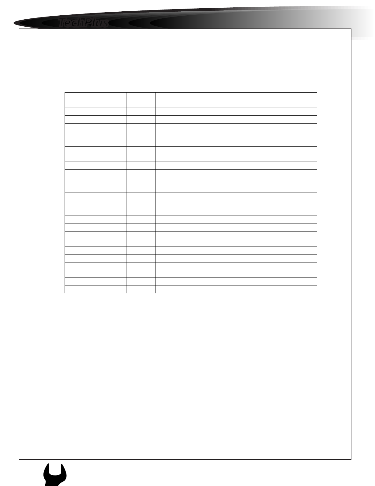
Maintenance Inspection Schedule
Weekly Monthly Semi
Annual
Annual Inspect/Service These Items
Electrical
• •
Check Compressor clutch operation
• •
Inspect D.C. fan motors
• •
Inspect wiring harness for damaged wires
or connectors
•
Clean and re lubricate power studs at
condenser
Refrigeration
• • •
Check refrigerant level
• •
Replace receiver drier
•
Check refrigeration lines for signs of
rubbing, damage, and oil leaks
•
Perform acid test on compressor oil
Structural
• • • •
Visually inspect unit for loose or broken
parts
• • • •
Clean defrost drains
• • • •
Inspect belts for proper tension
• • •
Clean entire condenser and evaporator
coils
• • •
Check all mounting bolts
Note: Use only PAG (Poly Alkylene Glycol) compressor oil in R-134a systems
Do not mix PAG compressor oil with other synthetic oils
Keep PAG oil in tightly sealed containers. If oil becomes contaminated with
moisture (colour will change to milky) or standard oils, dispose of properly – Do
Not Use
Note: When servicing a R-134a system, use only those service tools certified for
and dedicated to R-134a refrigerant and PAG compressor oils
` Residual or non HFC refrigerants or oils will contaminate the R-134a
System
Note: Recover all refrigerant and re cycle or dispose of properly
l
s e r v i c e s u p p l e m e n t
c c 8 0
1
16
APPENDIX
General Unit Description
The Blue Bird air conditioning unit is designed to provide comfort, at
temperatures between 70 - 80 ºF.
The typical A3RE/FE and BBCV system consists of three separate assemblies;
the condenser, evaporator and compressor. The Micro Bird has two completely
separate condenser, evaporator and compressor sets; the rear Comfort Aire and
chassis OEM system.
Comfort Aire offers condensers uniquely designed pair to mount on the roof, or
inside the skirt of the bus on the driver’s side. The large bus skirt side condenser
comes equipped with two separate condenser coils and three fans. Each of the
two roof top condenser units have a single coil and two fans.
The Evaporators are mounted inside of the bus, in this instance there are two
evaporators, one mounted on the curbside of the bus (Rear 1 Evaporator), the
other mounted on the road side of the bus (Rear 2 Evaporator). There is a third
non MCCII evaporator, incorporated into the front heater/defroster. This
evaporator is connected to the blue system hoses via a set of T-connections.
The compressors are mounted on top of the engine for the BBCV and
underneath of the CAT engines and on top of Cummins engines for the
A3RE/FE. The compressors are driven by the bus engine. Refrigeration lines are
used to connect the condenser, evaporator and compressor.
The two systems work separately.
Compressor operation is controlled by the drivers control switches and
thermostat, which energize the compressor clutch during engine operation. The
refrigeration system is protected by H. P. Binary Switch
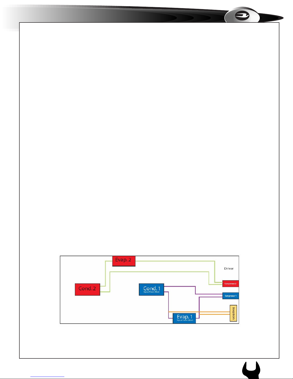
Below is a typical arrangement for a BBCV or A3FE with roof top condensers.
c O m F O r t A i r e A / c s Y s t e m sc c 8 0
1
APPENDIX
17

TechPlus
General Unit Operation
The unit will start operating as the driver turns on the blower switch for each side
of the bus; this sends electrical power to the compressor clutch. The compressor
clutch will engage as it is turned by the bus engine, through a compressor drive
belt.
Cooling
With the blower switch turned on and the temperature selector turned
(counterclockwise) towards the (C), electrical power is sent to the electronic
thermostat and through the. H.P. Binary Switch, and the compressor clutch. The
compressor clutch will engage, through a drive belt connected to the engine. The
engine will then turn the compressor.
During engine operation, the engine compressor, evaporator fans and condenser
fans operate while the unit is in cool.
Evaporator Coil Defrost
The defrost cycle can initiate at any time the evaporator coil reaches a
temperature of 30-32 ºF. This is controlled by the electronic thermostat and will
de-energize power to the compressor clutch. When the evaporator reaches 3537 ºF the thermostat will kick in and energize the compressor clutch.
Unit Features
x Dash mounted driver control
x Electronic Thermostat
x Compressor
x R-134a
Protection Features
x Control circuit breakers
x High Pressure – Low Pressure Binary Switch
l
s e r v i c e s u p p l e m e n t
c c 8 0
18
APPENDIX
1
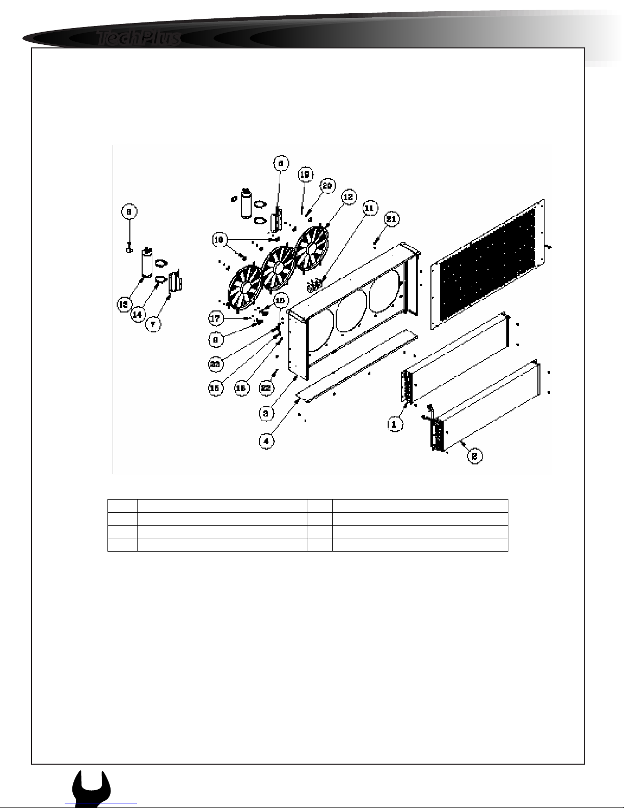
General System Component Details
Stacked Skirt Mounted Condenser Configuration
Power Stud
12 V Relay
H.P.Binary
Switch
Drier
Cond. 2
Cond. 1
c O m F O r t A i r e A / c s Y s t e m sc c 8 0
1
APPENDIX
19
TechPlus
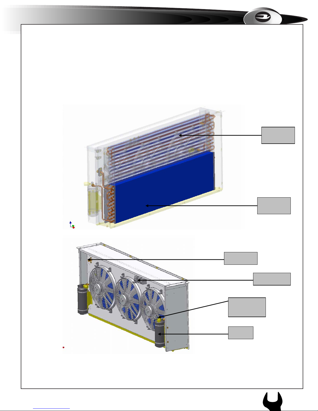
Stacked Skirt Mounted Condenser Exploded View
Components
1,2 Coils 4 Condenser Grill
6 H.P. Binary Switch 11 12 V Relays and Base
15 Receiver Drier
l
s e r v i c e s u p p l e m e n t
c c 8 0
1
20
APPENDIX

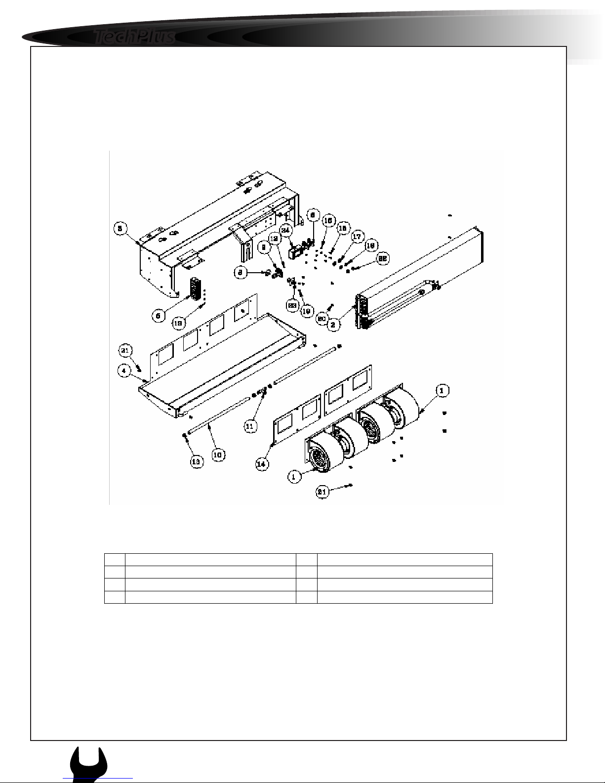
55,000 Bth/hr Free Blow Evaporator Configuration
Thermostat
Module
Power
Studs
Expansion
Valve
12 V
Relays
Air Filter
Directional
Louvers
Blower
Assy.
c O m F O r t A i r e A / c s Y s t e m sc c 8 0
1
APPENDIX
21
TechPlus
55,000 Btu/hr Free Blow Evaporator Exploded View
Components
1 Blower Assembly 2 Coil
5 12 V Relays and base 6 Power Stud
9 Expansion Valve 10 Defrost Drain Tube
l
s e r v i c e s u p p l e m e n t
c c 8 0
1
22
APPENDIX
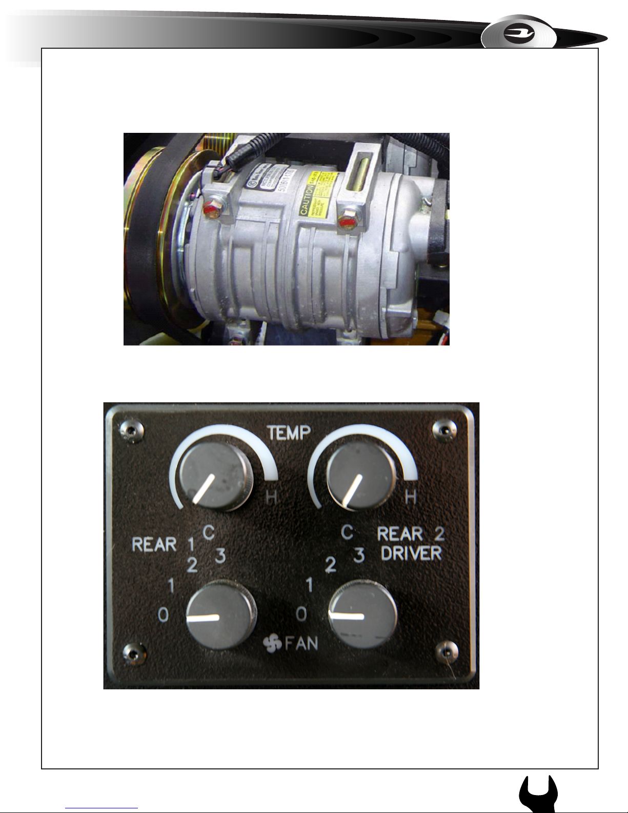
Typical TM-21 Compressor
Manual Control Panel
c O m F O r t A i r e A / c s Y s t e m sc c 8 0
1
APPENDIX
23
TechPlus
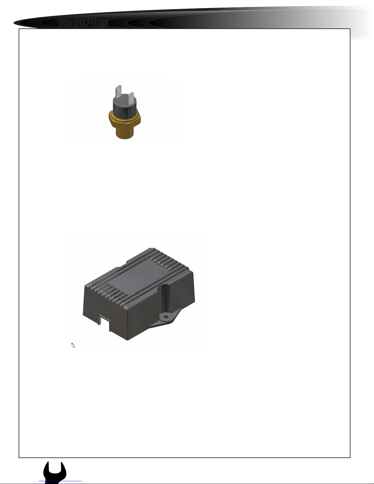
High Pressure Binary Switch
Typically located on or near the receiver drier, when the pressure in the high side
of the system reaches 385 psi, the switch will open, disrupting the voltage to the
compressor clutch. The clutch will disengage, causing the compressor to stop
working preventing serious damage from occurring to the system. The HP
Binary switch will then close once the pressure has reduced.
As well, when the pressure on the low side reaches 28 psi, the switch will open,
disrupting voltage to the compressor clutch. The clutch will disengage, causing
the compressor to stop working.
Electronic Thermostat
Located inside the evaporator cover, the thermostat serves a temperature control
and prevents the evaporator from freezing.
The thermostat is designed to open the circuit to the H.P. Binary switch when the
evaporator coil reaches 35 – 37 ºF.
l
s e r v i c e s u p p l e m e n t
c c 8 0
24
APPENDIX
1
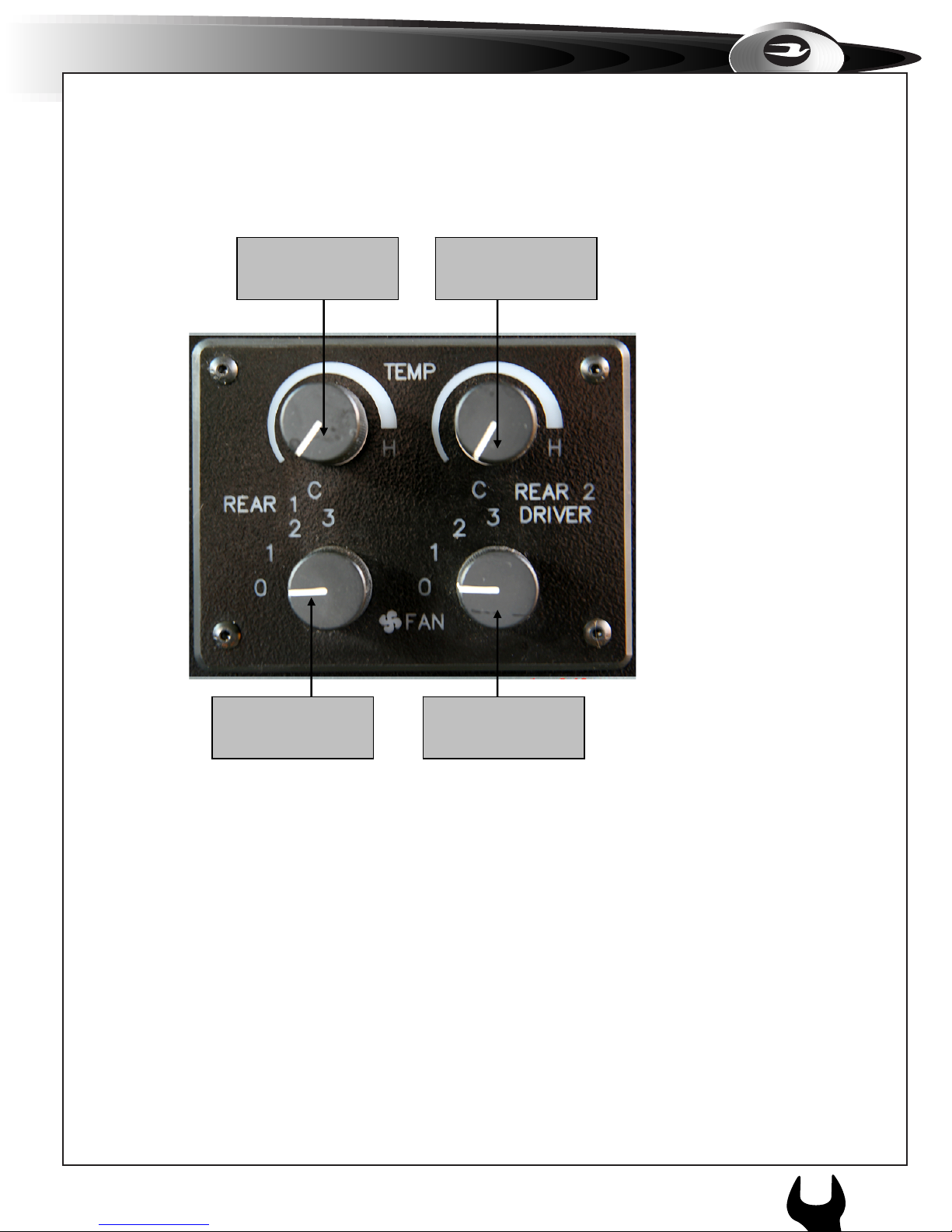
Driver Instructions and Information
Starting the Unit
1.Start the vehicle, and select both blowers switches to #3 high speed, select the
thermostat control switches to full cool (clockwise) towards H. The Micro
Bird will have only one Rear Temperature knob and one Fan speed knob on the
panel above the driver. The OEM A/C controls will be integrated into the dash.
2. Leave the unit running (if allowed, not legal in some municipalities) with all
windows and doors closed for a period of 10 – 20 minutes, to stabilize the
temperature of the bus.
3. Driver can control the desired temperature after the bus is loaded, by turning
either the blower switch or the temperature control switch to a comfortable level
for the passengers.
Evaporator 1
Thermostat Control
Evaporator 2
Thermostat Control
Evaporator 1 Blower
Speed
Evaporator 2
Blower Speed
c O m F O r t A i r e A / c s Y s t e m sc c 8 0
1
APPENDIX
25
 Loading...