

Page 1
Specifications
Wings pan: 815mm (32i n)
Fusel age len gth: 786mm (31i n)
Flyin g Weigh t: 130- 150g( with b atter y)
Instruction Manual
Yak54 F3PYak54 F3P
Before use,please read the explanations carefully!
lLaser-cut 3mm genuine EPS parts for optimum stre ngth an d
Minim um weig ht .
lLightweight carbon fiber truss system virtually eliminates flex .
lIdeal for indoor flight and capable of outdoor flight in low winds.
lMinimal assembly required flight ready in as little as 3 hours .
lVibrant screen printed trim scheme.
Warning
An R/C aircraft is not a toy! If misused, it can cause seriousbodily harm and
damage to property. Fly only in open areas,preferably AMA (Academy of
Model Aeronautics) approved flying sites, following all instructions included
with your radio.Always assume the electric motor can come on at any time
souse extreme caution.Before beginning assembly of your , we
strongly uggest that you read through this instruction manual so you
canbecome familiar with the parts and the assembly sequence.Assemble the
kit according to the sequence provided in the instruction manual. Do not
attempt to modify or change the kit design as doing so could adversely
change the models flying characteristics.
Yak54- F3P
s
Additional Required Equipment
Motor: 2404 KV:1600
ESC: 10 A
GWS
Radio 4 more c hanne l
Recei ver 4 mo re chan nel
Batte ry char ger
7.4V mAh
Prope ller: 9050 Sl ow Flye r Prop
Servo :5G* 3
: /
: /
Batte ry: 350
Introduction
Thank you for purchasing the Yak54-F3P.
The Yak54- F3P ARF has super slow flight responsiveness so you can fly highalpha 3D with authority. Its carbon fiber reinforced Yak54-F 3P construction
provides the solid, precise feel of a balsa profile plane without the weight. This
allows you to fly the Yak54-F 3P ARF outside in windier conditions that would
keep most other profile foamies grounded. The Yak54-F3P ARF is another
exciting addition to TECH ONE's outstanding line of electric RC aircraft and
accessories.
TECH ONE uses top-quality engineering and materials in everything it makes, so
you always get the maximum level of value and fun. TECH ONE backs all of its
products with the best customer service and support in the hobby so your electric
flight experience is always a positive one.
These assembly instructions are designed to guide you through the entire
assembly process of your new airplane in the least amount of time possible. Along
the way you'll learn how to properly assemble your new airplane and also learn
tips that will help you in the future. We have listed some of our recommendations
below. Please read through them before beginning assembly.
Required Tools and Adhesives (not included in the kit)
5 Minute Epoxy
Glue
Aerosol Zip-Kicker
# 0 and #1 Phillips Head Screwdrivers
1.5mm Hex Wrench
Adjustable Wrench
Wire Cutters
Z-Bend Pliers
Needle Nose Pliers
Modeling Knife
Scissors
Electric or Hand Drill
Assorted Drill Bits
Straight Edge Ruler
Pencil
T-Pins
Builder's Triangle
220 Grit Sandpaper with Sanding Block
Masking Tape
Paper Towels
Rubbing Alcohol
Epoxy Mixing Sticks
Epoxy Mixing Cups
Soldering Iron
Page 2
-2-
S
m
90
C/ A
Glue the fuselage side board onto the fuselage main board.
Install the round doublers onto the pre-reserved holes on the
bottom fuselage to strengthen the joint of carbon fiber rod and
foam.
Bracing
Install the round doublers on other places.
Install the doubler for the landing gear.
Cut proper length of carbon fiber rods, then install them into corresponding round
doublers. Note: The fuselage side board should be perpendicular to the fuselage main
board.
Install the round doublers, then fix the carbon fiber rods as shown to strengthen the fuselage and wing. Note: The whole plane should be
vertical, no distortion.
A
B
A= B
2.
34
0m
m
5
0m
3 m
02
0 m
m
10
5
mm
2 70
mm
Page 3
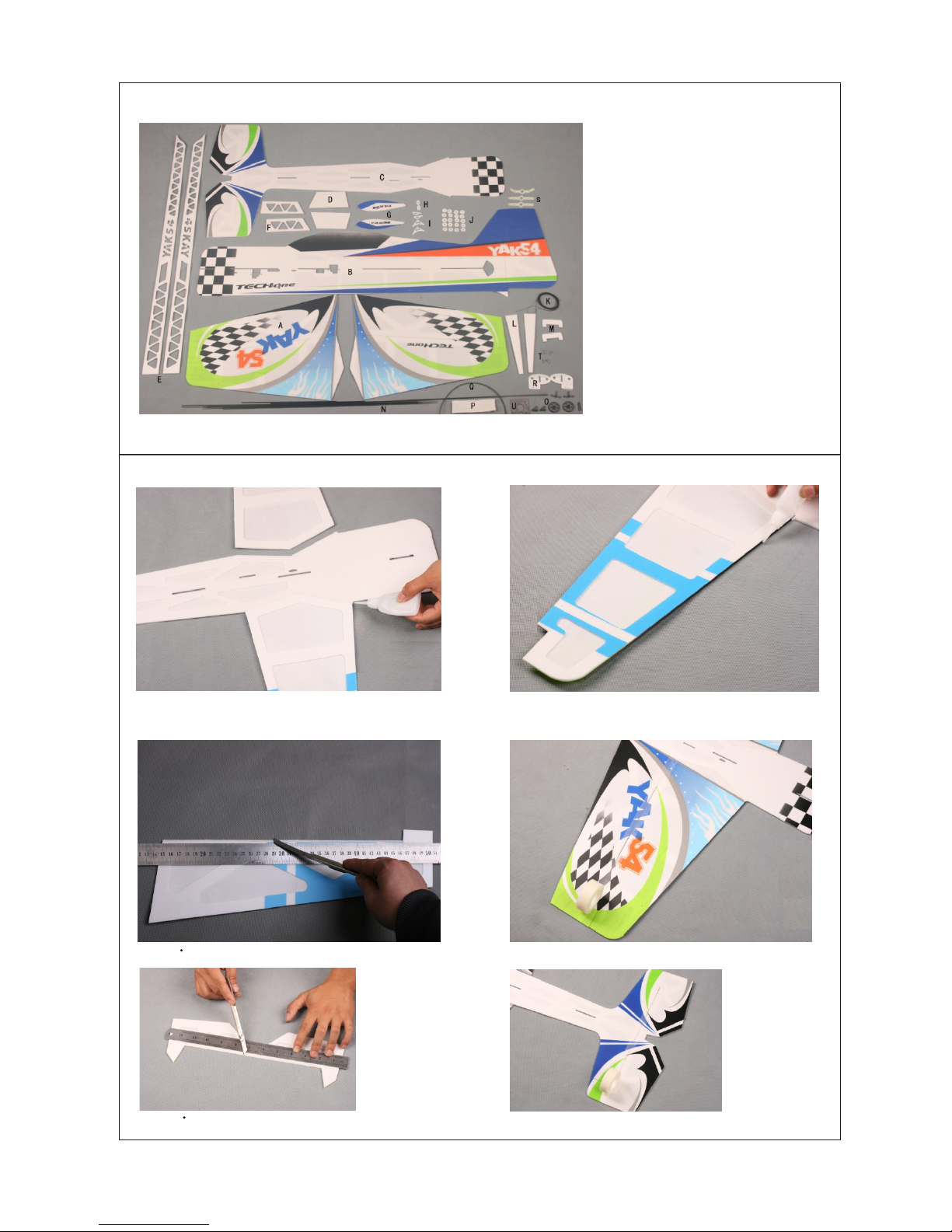
A Wing wit h Ailero n
B Fusel age Sid e Board
C Fusel age Mai n Board
D Wing Fe nces
E Foam Do ubler s (long )
F Foam Do ubler s (shor t)
G Wheel C overs
H Contr ol Horn B ackpl ates
I Contr ol Horn s
J Round D ouble rs
K Threa ds
L Lan ding Ge ar Deco F oam Str ips
M Motor F ixed Fo am
N Carbo n Fiber R ods
O Landi ng Gear s
P Velcro
Q Heat- Shrin k Tubing
R Doubl ers for L andin g Gears
S Servo Ar ms
T Screw s
U Plywo od Moto r Mount
Kit Contents
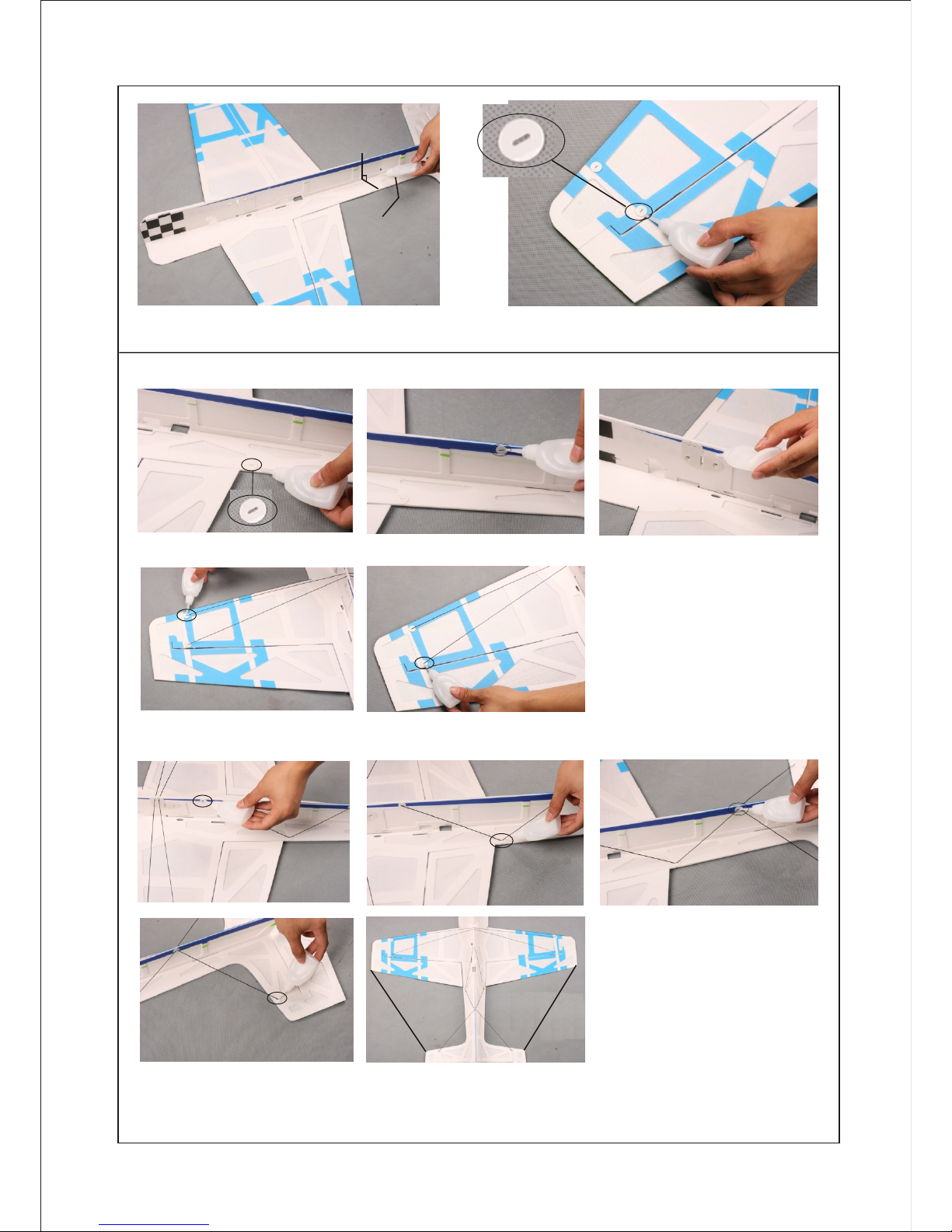
Glue 2 pcs ca rbon s trips on the front of the wings with
some fo am-fr iendl y C/A.
Use 3M magic tape to splice the aileron and wing.
Same assembly as the aileron and wing.
Fuselage and Wing Assembly
Glue the wings and fuselage together with foam-friendlyC/A.
Note: No distortion of the fuselage and wings.
-1-
1.
Cut a 45 be vel on th e eleva tor as sh own.
Cut 45 be vel on th e two ail erons .
Page 4

-3-
90
Landing Gear
Assemble the landing gears and fix them
with some foam-friendly C/A.
Fuselage
Fix the rudder with 3M magic tape.
Install the wing fences and fix as shown in the picture.
Install the motor mount and fix as shown in the picture.
Fix the foam doublers on the fuselage. Note: Keep the fuselage and wing vertical, no distortion.
S
C/A
s-fuselage side board
m-fuselage main board
fix them with some foam-friendly C/A.
3.
4.
Page 5

-4-
ailer on
servo
elevator
servo
rudder
servo
Servo and Servo Arm
Fix the servo arm with some C/A
Install aileron servo and fix with some C/A.
Install elevator servo and fix with some C/A.
Install rudder servo and fix with some C/A.
5.
Page 6

Control Horns and Servos
Glue together the contron horns and their backplates.
Aileron carbon fiber push rods.
Fix the aileron control horns with some C/A.
Install the push rods to connect the aileron servo and control
horns.
Fix the rudder control horns with some C/A.
Fix the elevator control horns with some C/A.
Link the servos and control horns with threads, make sure the threads are taut and the two ends of the servo arms are tied
with threads.
-5-
6.
167mm
Page 7

-6-
PRO TIP: After flying the airplane, you may want to add right
and/or down thrust to the motor. You can do this by adding
thin washers between the motor mount and the firewall.
Control System
Install the motor.
Fix the wheel covers with some foam-friendly C/A.
Mount your ESC to the fuselage, using one piece of velcro.
Use one piece of velcro to fix your receiver on the fuselage,
and also install your battery to the designated place on the
fuselage.
Lipo battery
7.
Page 8

Seek Assistance
If you are new to R/C we suggest you find an experienced pilot to check out your aircraft and help you with
the first few flights.This will help prevent damage to your model and will speed up the learning process
and making your R/C experience all the more enjoyable. You can contact local R/C clubs or your dealer
to obtain the names of experienced R/C pilots who would be willingto help you with your first few flights.
Although this is an ARF (Almost-Ready-to-Fly) kit, it does have some construction features that can be
challenging to the less experienced modeler. If you encounter difficulty in any construction sequence,
please feel free to contact one of our technicians, we stand ready to provide any assistance we can.
Contact us at:
E-Mail: techonehobby@gmail.com
Copyright 2009 Techonehobby
Http://www.techonehobby.com
TM
C
Balance Point
The Center of Gravity (C/G or Balance Point) is 2.9 5" (75mm)
from the leading edge of the wing, measured at the center of
the wing.
WARNING For test flying and general sport flying, we suggest
you balance the airplane at the C/G recommended above. For
3D flying, you may want to experiment moving the C/G back in
small increments until you're satisfied with the result.
Control thr ows
Sport Flyin g
Ailerons: 3 7. 2mm(1.46") Up and Dow n
Elevator: 2 9. 2mm(1.15") Up and D ow n
Rudder: 44m m( 1.7 3" ) Ri ght and Left
3D Flying
Ailerons: 1 02 .3mm( 4. 03")Up and Do wn
Elevator: 8 7. 6mm(3.45") Up and D ow n
Rudder: 132 mm (5. 20")R ight and Left
The control t hr ows are measu red from the wide st
point of the co nt rol surface s
Exponenti al
Sport Flyin g
Ailerons: 2 0%
Elevator: 2 0%
Rudder: 20%
3D Flying
Ailerons: 4 5% - 5 5%
Elevator: 4 5% - 6 0%
Rudder: 45% - 6 0%
Exponenti al s oftens the re sponse of the c on trol
surfaces ar ou nd neutral st ick. This m akes the airpla ne
easier to con tr ol while usin g such large cont rol throws.
The Exponen ti al values sho wn are given as a per cent.
Please note t ha t diffe re nt brands of ra dio control
systems may c al l for + or - Expo. Pl ease check yo ur
transmitt er 's owners man ual for more in fo .
-7-
Motor Thrust
To ensure great flight performance and to be able
to trim your airplane properly, it is critical that you
adjust the motor thrust as described. We suggest
that you add 2 degrees of down-thrust and 1
degrees of right-thrust. This can be achieved by
adding a washer or two behind the top and right
side of the motor (between the motor and the
firewall). When set properly, the trim for the
elevator and the rudder should be neutral. Finetune the down-thrust and right-thrust until this trim
is achieved.
Made in China
 Loading...