

Page 1
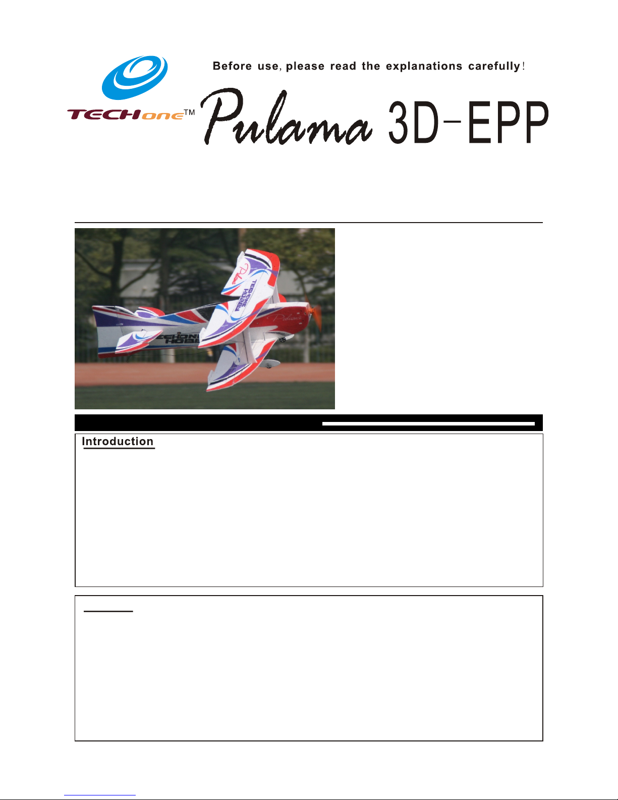
Thank you for purchasing the Pulama 3D Indoor flyer.
The Pulama 3D is engineered to be as adept at slow-speed 3D as it is precision aerobatics. The biplane
design not only provides crisp roll response, but also it gives the Pulama 3D superb slow flight stability
so you can fly high-alpha 3D with authority. Its carbon fiber reinforced Depron foam construction provides the
solid, precise in-flight feel of a balsa profile plane but without the weight.
The Pulama's biplane design increases the wing area and dramatically reduces wing loadin g so h ov er in g
and slow flight 3D can be performed with more precision. Plus, the shorter wingspan makes for crisper roll
rates at all speeds.
These assembly instructions are designed to guide you through the entire assembly process of your new
airplane in the least amount of time possible. Along the way you'll learn how to properly assemble your new
airplane and also learn tips that will help you in the future. We have listed some of our recommendations
below. Please read through them before beginning assembly.
-EPP
-EPP
-EPP
ELECTRIC 3D FLYER ARF
Instruction Manual
Specifications
865mm (34.1 in.)
800mm (31.5 in.)
400 sq in (25.8 sq dm)
Fuselage length:
Wingspan:
Wing Area:
Flying Weight: 260g- 285g (with battery)
Additional Required Equipment
C20 or 2205 brushless motor
18Amp brushless ESC
8040 slow flyer prop
5- 8
11.1V 500-800mAh Li-po
Motor:
ESC:
Propeller:
Servo: g
Radio:4/ more channel
Receiver:4/more channel
Battery charger
Battery:
Www.techonehobby. com
Warning
1. -EPP is not a toy and is not suitable for the flyer under 14 years.
2.Do not fly near houses or buildings children's play areas road traffic railways airports, overhead power
lines and pylons. Do not fly over people.
3.
4. .
5.Do not fly in the strong winds.
6.Do not try to catch the plane by hand when it is flying.
7.The children who are younger than 14 years old should be assisted by an experienced adult when the plane
is being flown.
The Pulama 3D If misused, it can cause
serious bodily harm and damage to property.
, , ,
Fly only in open areas, preferably AMA (Academy of Model Aeronautics) approved flying sites, following all
instructions included with your radio.
Assemble the kit according to the sequence provided in the instruction manual
Page 2
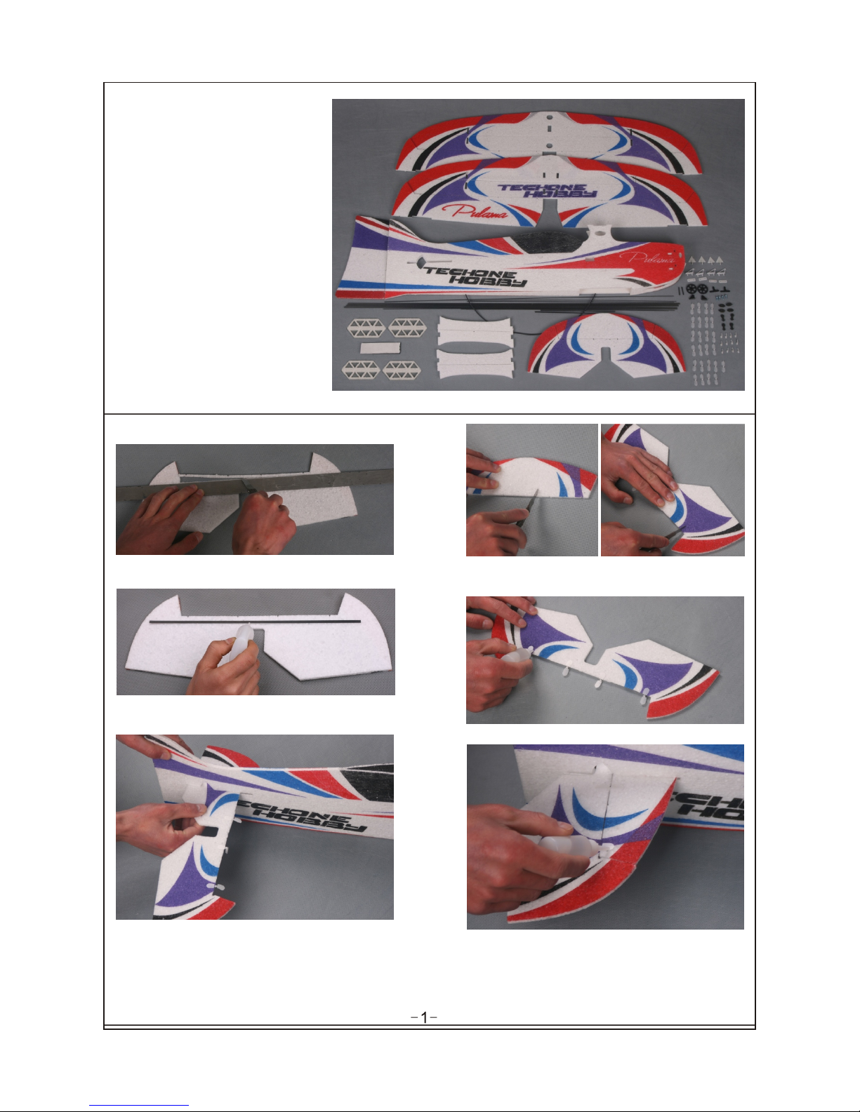
1. Horizontal Stabilizer
Fuselage - 1
Bottom Wing with Ailerons - 1
Top Wing with Ailerons - 1
Horizontal Stabilizer - 1
Elevator - 1
Rudder - 1
Outer Wing Struts - 2
- 4
Wheel Covers - 2
Main Gear Wheels - 2
Landing Gear Struts - 2
Pushrod Supports - 4
Plain Wires 0. 8*360 - 1
Control Horns - 4
Carbon Fiber Strips 1* 4*800 - 3
Carbon Fiber Strips 1* 4*400 - 1
Carbon Fiber Rods 1. 3*700 - 7
Heat-Shrink Tubing 1. 5*400 - 1
Wood Screws - 4
Velcro 100mm - 1
Clevis - 12
Hinges - 25
Spoiling Flap
Kit Contents
Sand a 45º bevel into the b ot to m leading edge of
the elevator.
Cut four slots where the hinges will be installed
.
,
make sure the distance is symmetrical
Insert the hinges into the , then glue the cutslots .
Insert the elevator into the fuselage and center
it.
Insert the stabilizer into the fuselage, against
the elevator, glue the hinges on it.
Glue the carbon strips on the elevator.
Page 3
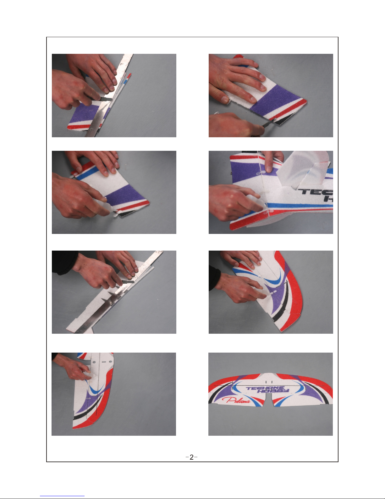
2. Vertical Stabilizer
Sand a 45º bevel into the left side of the leading
edge of the rudder.
Sand a 45º bevel into the bottom of the leading
edge of the four wing ailerons.
Cut sl ot s the
slots .
the same on stabilizer, then insert
the hinges into the , and glue the cut
Insert the hinges into the , then glue the cutslots .
Cut four slots where the hinges will be installed
.
,
make sure the distance is symmetrical
Cut sl ot s the
slots
.
the same on wings and wing
ailerons, then insert the hinges into the ,
and glue the cut
Hinge the ailerons to the top wing, using the
same techniques that you used to hinge the
bottom wing.
Cut a piece of carbon fiber strip as long as the
slot of the wing, then glue it to the slot.
Page 4

3. Wing
Glue the bottom wing to the fuselage, make sure
the slots in the wing are pushed firmly over the
mounting tabs on the fuselage.
Glue the h to orizontal stabilizer the fuselage.
Glue the two outer wing struts to the bottom
wing, make sure the wing struts are
perpendicular to the wing.
A
C
D
B
Make sure A=B, C =D.
Cut two carbon fiber strips as long as the slots of
the outer wing struts, then glue them to the slots.
Glue the top wing to the center wing mount and
the outer wing struts, make sure the wing is
perfectly flat while the glue cures.
Glue the two carbon fiber rods to wings.
Push the carbon fiber rod down through the
outer hole in the top wing (A) and slide it
through the hole in the outer wing strut (B).Push
the end of the carbon fiber rod through the inner
hole in the bottom wing (C).
A
C
B
Page 5

Glue the two carbon fiber rods to the .stabilizer
Cut two pieces of carbon fiber rod of 160mm.
Install them as above picture.
4. landing Gear
Push the landing gear strut into the precut hole
in the fuselage side, then twist the landing gear
strut so that the axle is straight.When satisfied
with the alignment, glue the landing gear strut to
the fuselage side and the bottom wing.
Inst all the two whe els and wheel c hocks.
Keep 1 mm distance b etween whee l and its
choc k. Apply some foam-friendly thick C/A
to glu e the chocks.
Glue the two wheel covers together.
Slide one wheel cover onto each axle and up
against the wheels. Align the wheel covers, then
glue them securely to the axles.
Cut one piece of carbon fiber rod of 50mm, then
insert it to the fuselage and glue it.
Page 6

Install the aileron control linkage.
Cut two pieces of carbon fiber rod to a length of 150mm, four pieces of heat-shrink tubing to a length of
25mm,four pieces of plain wire to a length of 38mm.Heat the heat-shrink material with a heat gun to shrink it
into place. For extra security, apply some C/A to the end of the pushrod and allow it to "wick" into the joint.
5. Control System
Install the aileron, elevator and rudder servos
into the servo mounting hole in the fuselage.
Use some glue to secure them into place.
Because the size of servos differs, you may
need to cut the servo mounting hole larger to fit
your particular servos.
Install the control horns.
Glue them to the ailerons.
Cut two pieces of carbon fiber rod of 60mm,
then follow the same steps.
Install the rudder control linkage(480mm).
Slide two plywood pushrod supports over the
end of the carbon fiber rod .
Notice: Glue the plywood pushrod supports to
the fuselage after finish the installation of
linkage.
Page 7

6. Final Assembly
Install your battery into the battery compartment,
using a piece of hook and loop material.
Mount your ESC and receiver, using a piece of
hook and loop material.
Install the cabin door with the same way.Glue the spoiling flap to the wing.
Install the elevator control linkage(380mm).
7. Motor
Apply some foam-friendly C/A
into the four motor mount
screw holes in the firewall.
Install the motor assembly onto
the firewall, using the four wood
screws provided.
I nstall the and propeller onto the
motor.
Page 8

Balance Point
The Center of Gravity (C/G or Balance Point) is 72mm from
the leading edge of the TOP wing, measured at the center of
the wing.
WAR NI NG F or t es t fl yi ng a nd g en er al s po rt f ly in g, w e
suggest you balance the airplane at the C/G recommended
above. For 3D flying, you may want to experiment moving
the C/G back in small increments until you're satisfied with
the result.
Control throws
Sport Flying
Ailerons: (28mm)1. 10" Up and Down
Elevator: (32.4mm) 1. 2 8" Up and Down
Rudder: (40mm)1. 57" Right and Left
3D Flying
Ailerons: (70mm)2.76" Up and Down
Elevator: (81mm)3.19" Up and Down
R udder: (100mm)3.94" Right and Left
The control throws are measured from the widest point
of the control surfaces
Exponential
Sport Flying
Ailerons: 20%
Elevator: 20%
Rudder: 20%
3D Flying
Ailerons: 35% - 50%
Elevator: 35% - 50%
R udder: 35% - 50%
Exponential softens the response of the control surfaces
around neutral stick. This makes the airplane easier to
control while using such large control throws. The
Exponential values shown are given as a percent. Please
note that different brands of radio control systems may call
for + or - Expo. Please check your transmitter's owners
manual for more info.
Motor Thrust
To ensur e great fligh t performan ce and
to be ab le to trim your a irplane pro perly,
it is cr itical that y ou adjust the m otor
thru st as describ ed. We suggest that
you ad d 2 degrees of do wn-thrust a nd 1
degr ees of right- thrust. This can be
achi eved by addin g a washer or two
behi nd the top and ri ght side of the
moto r (between th e motor and the
fire wall). When s et properly, the trim for
the el evator and th e rudder shou ld be
neut ral. Fine-t une the down- thrust and
righ t-thrust un til this trim i s achieved.
 Loading...