

Page 1
1
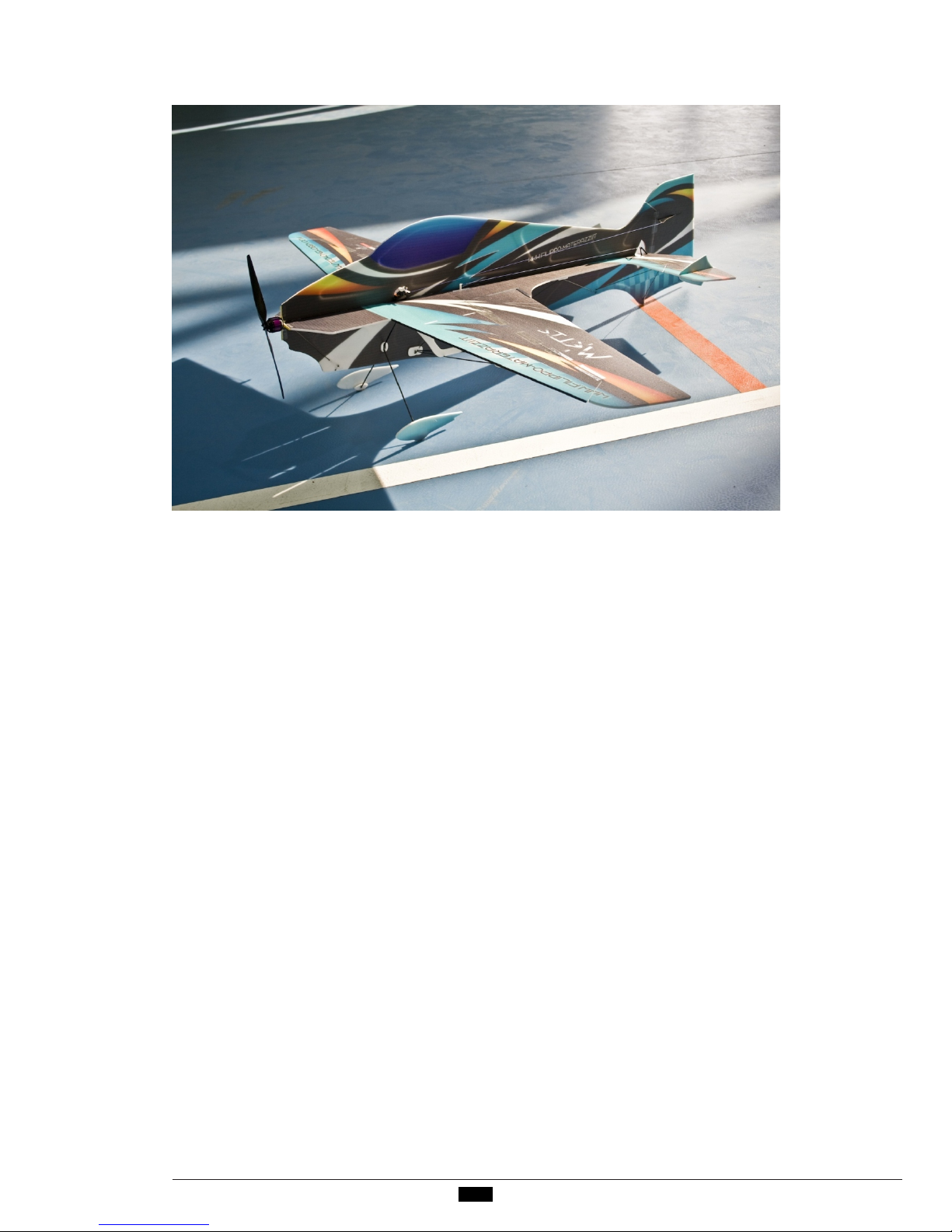
The Metis was designed by Filippo Materazzi, F3P, Aeromusical and
F6A Italian Champion. It is the last version of his famous indoor
freestyle airplane which he flew in World Air Games 2009. It has
been totally updated but maintaining its particular style. Now it has
bigger mobile surfaces, a higher top and bottom fuselage and a
completely new milling, paying attention to maintain the strength of
the airframe. Thanks to all these tricks it flies slowly and smoothly
but it can become very agile, reactive and fast if you need it. This
characteristic is fundamental for an aeromusical flight where you
need to change the flight style according to the music, but also in a
good freestyle, to differentiate the maneuvers and employ the own
imagination. In addition, a beginner can improve his skills gradually,
increasing step by step the movement of mobile surfaces.
The kit is composed by 3 mm and 2 mm depron, carbon rods (precutted!),
super lightweight carbon control horns and all the
necessary to complete the plane.
Before assembly, please spend some time to read our instructions.
Along the way you’ll learn how to properly assemble your new
airplane in the least amount of time possible. Below are some tips
that will help you in the assembly.
Before operating this unit, please read these instructions
completely.
MET I S I NSTRUCTION S
Page 2

2
1. You need to consider the reserved servo position when installing
the elevator and rudder. Also make sure that moving control
surfaces do not interfere with reinforcement parts such as
strings and linkage poles.
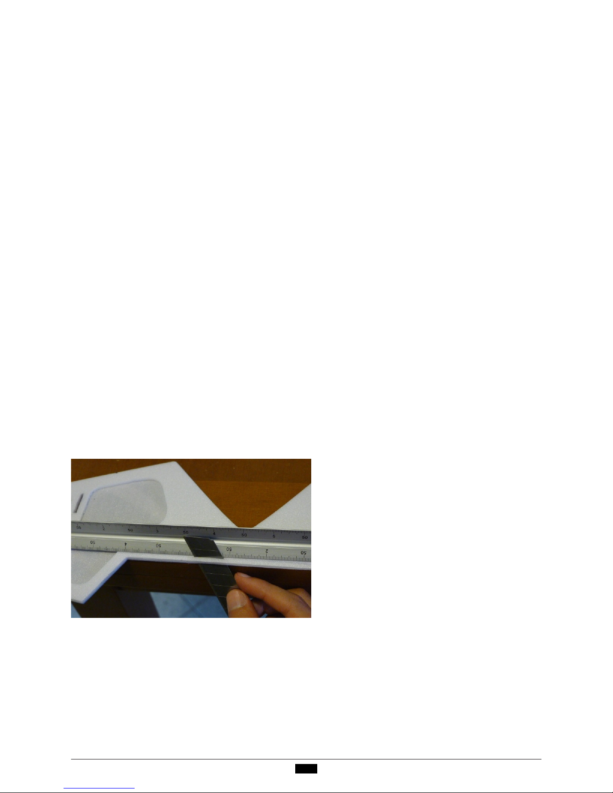
2. Before fixing carbon with C/A, paper the par t that is going to be
inser ted and fixed in the depron. In this way you can have a
stronger glueing.
3. Glue the carbon rods exactly as shown in the pictures. To obtain
a rigid and strong plane is very important that the ends of carbon
rods touch and are glued together.
4. Cor rect assembly can assure good flying, before using glue or
adhesive, please check the parts position and angle of alignment.
5. Remember to use less glue as possible and to use the lightest
electronic parts you find. Less weight means always better flying
characteristic!
6. If you want for your plane the best flying characteristic I suggest
you to use the high quality electronic parts that I tested and I use
on my planes.
Fil i p po Materazzi
Product S p e cification s
Fus e l a g e l e ngth: 95 cm (37.4 in. )
Wingspan: 90 c m ( 3 5.4 in.)
Flying we i ght without bat t er y: 120 - 130 g (4.2 3 – 4 . 58 Oz)
Flying we i ght with batte r y: 140 - 150 g (4.93 – 5.2 9 O z )
Mot o r : 15 – 22 g (0.52 – 0 . 7 7 Oz) (suggested: Hacker A10 - 9 L )
ESC : 7 - 1 0 A mp (suggested: Hacker Mast e r ECO 08)
Propell e r : about 8 x 4 (sugges t e d : Mejzlik 8x4)
Ser vo: 6g x 4pcs ( s u g g e sted: 4 x JR DS318 or 3 x JR DS 3 1 9 HV)
Rad i o : 5/more channel (su g g e s ted: 2 - 5 g receiver )
Batter y: 2S 250- 3 5 0 mAh LiPo (su g ge s t ed: 15 – 22 g batter y)
Page 3
3
Do not fly under the conditions below
Windy conditions
A street with many trees or street lamps
Close to high voltage electrical wires
High Population density areas
Cautions for flying
Metis is made for indoor flight. Of course it is able to fly outdoor in
not much windy condition. Make sure you have permission to fly and
follow safety guidelines set by local authorities.
Note for Storage
Please disconnect the lipo packs when finished flying
Do not press or crush the airplane when storing
CG Position: 23.5-24.5 cm from the nose
Page 4
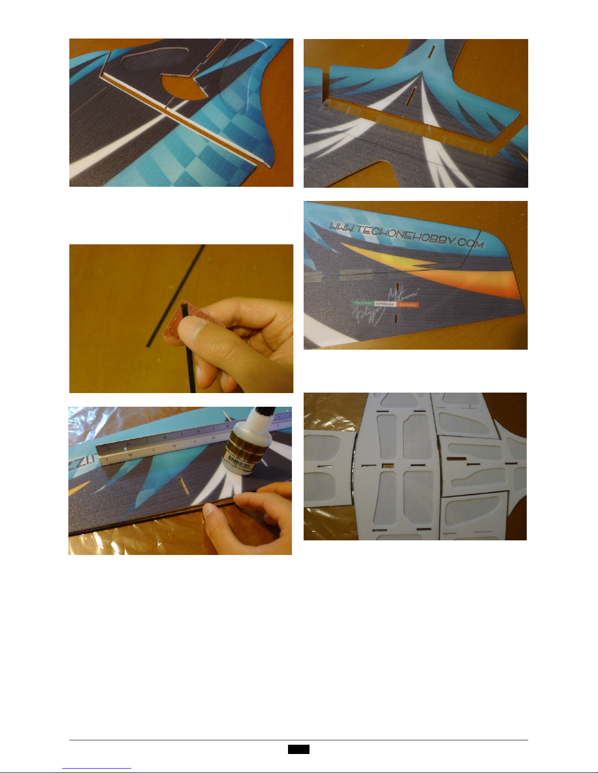
Use some C/A to glue the two carbon strip
(73 and 79.2 cm long) on both sides of the
wi n g as s how n i n th e pi c t ur e . NOTE:
pos i t ion the wing on a flat s urface.
Fix t he e l ev ator w ith 3 M ta p e.Do the
same with ailer ons.
4
Cut a 55º bevel on ailerons. On elevator
and r udder cut a 40° b eve l on m obil e
and f i xed surface .
Fix the horizontal fuselages to the wing
with C/A.
Page 5

Ins e r t the dow n s ide vertical wingl e ts
int o t h e pr e -r e s er ved sl o ts o n the dow n s i d e o f t h e w i n g a n d a p p l y s ome
C/A t o f i x.
Inse r t the p ar ts t o r e infor c e c o n tro l
surfa c e s i n t o t h e pr e-r e s er ved s l ots
on ai l e r o n s and a ppl y some C/A to fix.
Fix w i t h C/A the two 2 mm de p r on r ei-
nforcement parts on both sides of lower
vertical fuselage. A micro hole indicates
the position. In a consecutive step you
will have to inser t in it the four 1.5 mm
car b o n r o d s to r e i nforce the wings.
Fix w i t h C/A the two 2 mm de p r on r einforcement parts on both sides of lower
vertical fuselage where there is the hole
for the landing gear le gs.
5
Use s o m e C/A to fix the lower ver tical
fus e l a g e o n th e ho r iz o n t al f u s e la g e .
Be ver tical a n d no distor tio n !
Page 6

Ins t a ll all the carbon rods as shown in
the pict u res . Fir st o f all fix w it h C/ A
the f o ur 1 . 5 mm ( 29 .3 c m l on g) w i ng
car b o n r o d s . T hen t h e o ther s 1 m m carb o n r o d s .
Fix w i t h C/A the four 2 mm d e p r o n r einfor cement par ts on the bottom of wing
at the end of each 1 .5 mm wing carbon
rod.
6
Fix w i t h C/A the four 2 mm depron r einfor cement half-moons on the bott o m
of horizontal fuselage as shown in the
pic t u r e . T he micr o hole s indicate the
pos i t ion. T h e y ar e n ecessar y to reinfor c e t he points where the 1 mm carbon r ods wi l l b e fixed.
Page 7

Install the landing gear. Please inser t
through the pre-reserved holes on the
fus e l a g e a n d wing the two 2 mm x 24
cm ca r b on r o ds, then use C/A to fix.
Fix with C/A the three 1 mm carbon rods
as shown in the pictures.
Fix with C/A the 0. 8 mm carbon rods to
reinforce the a i l e r ons.
7
Fix with C/A the two 3 mm round depron
reinfor c e ments on the bottom of horizontal fuselage as shown in the picture.
The micro holes in d i c ate the position.
Th e y a r e n e c essa r y to r ein f o rce the
joi n t o f the landing gea r l e gs.
Page 8

Us e s om e C/A to fix the rudder ser vo in
the pre-reserved slot on the upper vertical fuselage as shown in the picture.
Use some C/A to fix the two aileron servos in the pre-reserved slots on the downside vertical winglets as shown in the
pic t u r e .
Use some C/A to fix the elevator ser vo
in the pr e-reser ve d s l o t on t h e lo w er
vertical fuselage as shown in the picture.
8
Send the lower par t of control hor ns.
Fix with C/A the two ailerons control horns.
Inst a l l th e 1 m m x 16 c m c a rb on r o d
payi n g attent i on to t he el evat o r deflect i o n. AT T ENTIO N : elevato r, wh e n
move s down, m u st no t touch t h is ca rbon r od!
Page 9

Insert the 0.5 mm x 32.5 cm carbon strip
in the elevator contr ol hor n. Then glue
them together in the pre-reser ved slot.
ATTENTION: elevator and rudder control
horns are asymmetric. The shorter part
goes on the side of mobile surface where
the r e is th e b eve l for movement.
9
Fix with C/A the 1 mm x 14 cm carbon rod.
Then fix the rudder control horn.
Ins t a ll the rudder to the fuselage with
som e 3 M t a p e.
Use C / A t o fix the upper vertical fuselage into t h e horizontal fuse l a ge. Be
ver tical, n o d i stor tion.
Ins e r t the four 2 mm winglets int o the
pre-reserved slots on the elevator and
apply some C/ A t o f ix.
Page 10

Connect the elevator and rudder servos
and c o n tr ol h or n s w i th thr ead. Make
su r e t h e th re ad i s t au t an d have t he
control surfaces in a horizontal position.
10
10
Install the motor with 3M tape and C/A.
Fix the small depron piece to the wheel
pa n ts t o re in f or ce th e m. P i er ce t h e
wheel pan t s a nd fi x the m wit h C/A in
the landing gear as shown in the picture.
Fix w i t h C/A a small piece of velcro on
each w h eel pant.
Use r ecei ver to trim the ser vo ar ms in
neutral, then fix the servo arms. Install
ail e r on s l i nka g es using the fo u r clips
and t h e t wo 1.3 mm x 5 cm carbon rods
included in the kit .
Page 11

2
11
Us e s ma ll p i ec es o f velcr o t o fix the
ESC , receiver and batter y. NOT E : you
can a d j ust the place of batter y according to the C G p o sition.
A per fect Metis is done a f t er your carefu l a s sembly. While assembly, th e f l yin g weight is really critical to t h e f light p e r for man c e a nd will be affected
by adding weight, so you should reduce
any unnecessary weight while assembly.
Then yo u ’ ll g e t t he best flying perfo r man c e .
Do th e s a me on “tail landing g e a r” as
shown in the picture.
Page 12

12
For technical informations about planes,
pls co n tac t with:
fili p p o.materazzi@gmail.com
www.fmdplanes.com
www.filippo-materazzi .it
www.techonehobby.com
Email:techonesales4@ gmail.com
 Loading...