

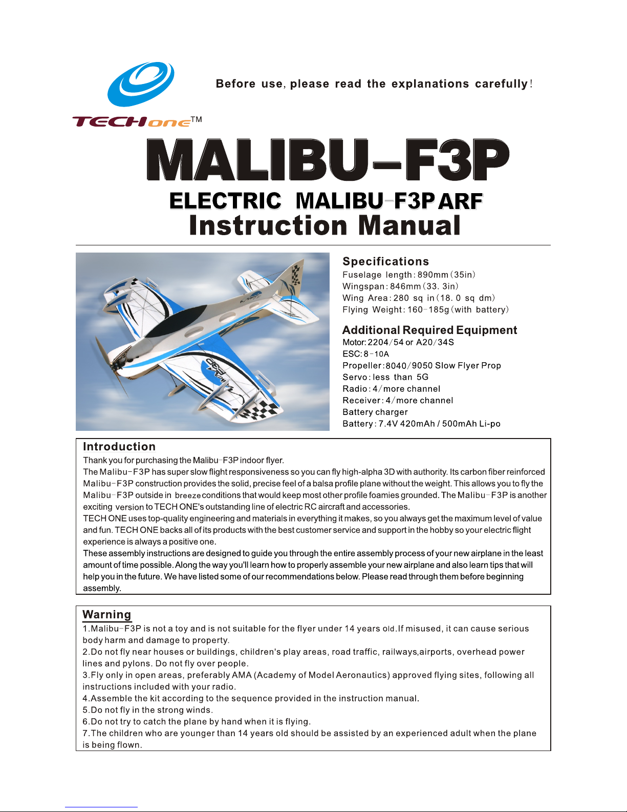
Page 1
Page 2
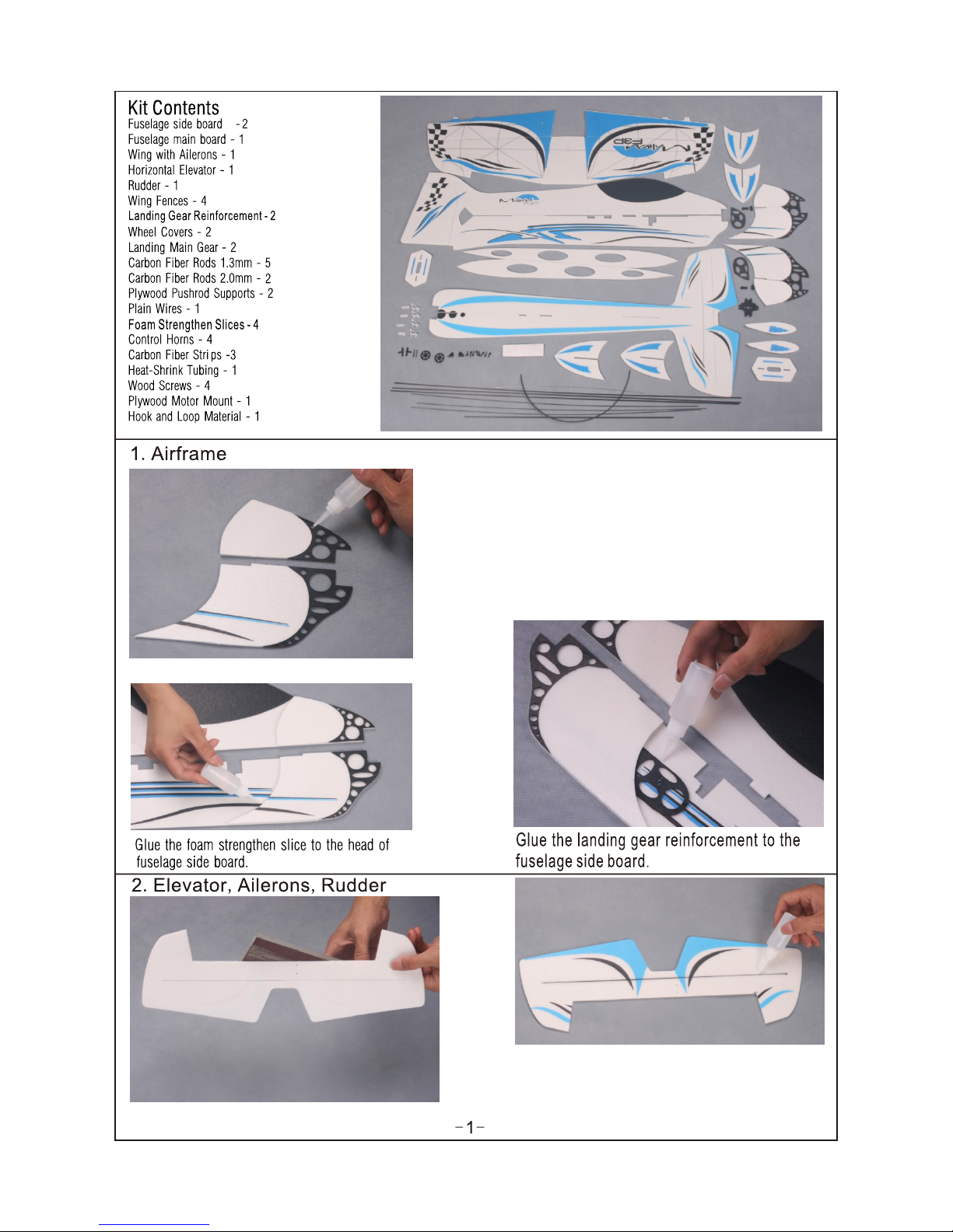
Sand a 45º bevel into the bottom leading edge of the
elevator.
Cut a piece of carbon fiber strip to a length of 14-2/3"
(376mm), then glue it to the below of the elevator, using some
foam-friendly C/A. Make sure the elevator is flat and the
leadingedge is straight while the glue cures.
Page 3
While holding the elevator tight against the stabilizer, apply a strip of
clear plastic tape (not included) to the top of the hinge line on both
sides of the elevator.
Sand a 45º bevel into the left side of the leading edge of the
rudder.
Sand a 45º bevel into the bottom of the leading edge of
the two ailerons.
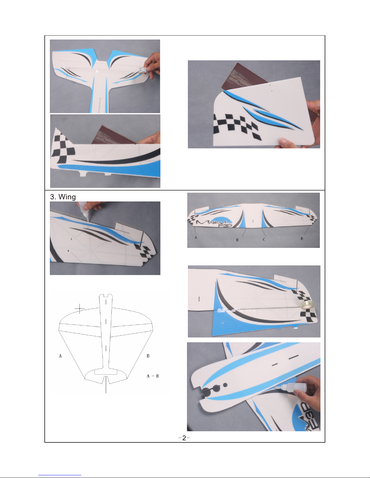
Use foam-friendly C/A to glue the carbon strips to A and
B to strengthen the wings.
Use some tape to warp the carbon strips on A,B,C and D showed in
the picture to avoid the carbon falling off.
Glue the wings with aileron to fuselage.
Notice:Measure from the tips of the wing to the rear of
the fuselage. The measurements must match from right
to left. If not, adjust the position of the wing until both
measurements are equal.
Page 4
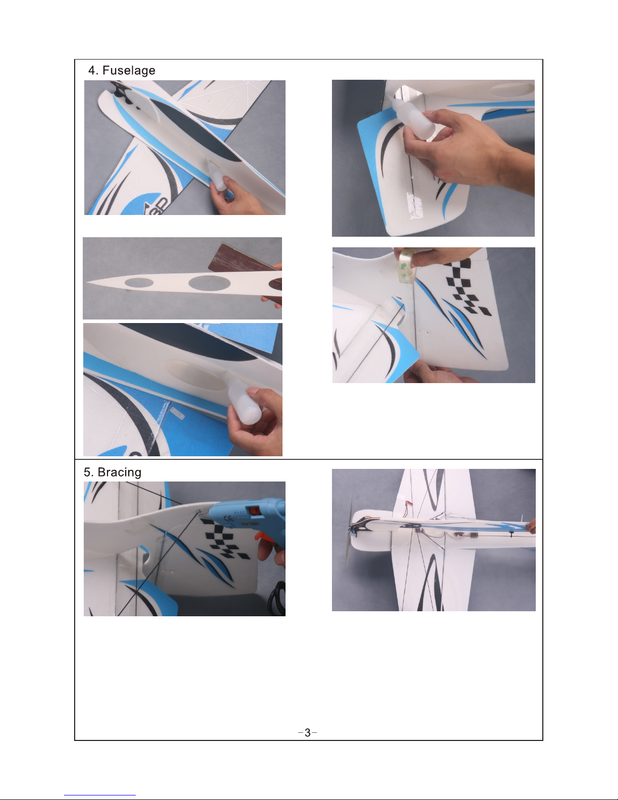
Glue the side board and main board of fuselage.
Make sure the side board is vertical to the main board.
Hinge the rudder to the back of the fuselage, using the same
techniques that you used to hinge the elevator to the
stabilizer.
Locate the two carbon rods. Pass the rods through the fin and
stabilizer. Put the rods together in the fin and use foam-friendly
C/A to glue the rods to the fin ONLY at this time.
Use a square to align the stabilizer with the fin.Once the fin is
perpendicular to the stabilizer, use foam-friendly C/A to glue the
carbon rod to the stabilizer. Square each side before gluing the rod
on that particular side.
Installing the wing bracing is similar to installing
the fuselage bracing, as you want the rods to be
glued to the carbon bracing that has been preinstalled
on the wing and fuselage. The rods are staggered and
fit into notches in the fuselage. Make sure the rods
are straight and are not flexing the wing. Use foam-friendly C/A
to glue the rods in position. The wing
should be flat and parallel to the horizontal stabilizer,
while also being perpendicular to the horizontal stabilizer
While also bei ng perpendicul ar t o the vertic al
fuselage.
Page 5

Install the prope lle r adapter onto yo ur motor, using
the screws p rovided with you r mot or. In sta ll th e motor
mount ont o your motor, using the sc rews provided
with your motor.
Glue the firewal l to th e hea d of th e plane.
Install the moto r ass emb ly on to the firewall, using t he
four wood screws p rov ide d.
PRO TIP After flyin g the a irp lan e, you may want to add
right and/or dow n thr ust t o the m otor. You can do this
by adding thin was her s bet wee n the motor mount and
the firewall.
Cut two pieces of carbon fiber rod , then cut two
pieces of heat-shrink tubing to a length of 1-1/2" (38mm).
Cut two pieces of plain wire to a length of 1-1/2" (38mm), then
make a L-Bend in one end of each piece of wire and a 4mm
long 90º bend in the other end of each piece of wire.
Secure one piece o f wir e to on e end o f the carbon fiber
rod, using one pie ce of h eat -sh rink material. Th e pie ce
of wire should ove rla p the c arb on fiber rod at least 1"
(25mm). Heat the h eat -sh rin k material with a heat gun
to shrink it into pl ace .PR O TIP F or extra security, a pply
a few drops of foam- fri end ly th in C/A to the end of the
pushrod and allow it to " wic k" in to the joint.
Page 6

Slide one plywood pus hro d sup ports over the end of
the carbon fiber r od an d tem por arily push the
plywood pushro d sup por ts in to the one precut slots
in the fuselage.
Center the e lev ator and rudd er servo s, then glue the
servo arms on .
Install the horn of aileron same as the horn of stabilizer.
Install wheel covers on the chock beside the wheel.
Screw one more chock outside of the cover, glue it.
Make s ure that both landing
gear strut are even w ith eac h
other(the same distance from
the botto m o f the w ing )or else
the airplan e won 't sit l eve l on
the ground.
Install the two wheel s and w hee l cho cks .keep
1mm d ist an ce bet we en whe el and i ts
chock.Apply some foam-fr ien dly thic k C/A to
glue the chocks.
Install the elevator aileron an d rudder servos into
the se rvo mo unt ing ho le in the ri ght si de of the
fuselage.Use a dab of foam-f rie ndl y th ick C/ A t o
secure them into pla ce. Bec aus e the size of servos
are differe nt, you m ay ne ed to c ut th e ser vo mo unt ing
hole larger to fit y our p art icu lar servos.
Page 7

Glue four wing fen ces t o the w ing , make sure that
the trailing edg e of ea ch wi ng fe nce is even with
the aileron hinge lin e. Us e a bui lder's triangle to
make sure that the w ing f enc es ar e perpendicular
to the wing.
Mount your ESC to th e fus ela ge si de, using a piece
of double-side f oam t ape ( not i ncluded).
Plug the servo and E SC le ad in to th eir proper slots in
your receiver,t hen m oun t you r receiver to the side of
the fuselage, op pos ite t he ES C, using
a piece of double- sid ed fo am ta pe (not
included).Dr aw th e ant enn a out the bottom of the
fuselage and sec ure i t alo ng it s length, using pieces
of clear tape (not i ncl ude d). D o not cut the antenna
shorter. Allow the e xce ss to h ang b eyond the back of
the fuselage.
Insta ll yo ur battery into t he battery compart ment,
using a p iece of hook and loop ma terial.
Installing the p rop ell er an d decals.
Balance your pro pel ler, t hen i nstall it onto your
motor.Using a cle an cl oth w ipe t he airframe down
completely to re mov e any d ust , debris and oil.
Page 8

BALANCE POINT
The Center of Gravity (C/G or Balance Point) is 3" (77mm) back
from the leading edge of the TOP wing, measured at the center of
the wing.
WARNING For test flying and general sport flying, we suggest
you balance the airplane at the C/G recommended above. For 3D
flying, you may want to experiment moving the C/G back in small
increments until you're satisfied with the result.
Control throws
Sport Flying
Ailerons: (26 .4mm) 1. 04" U p and Down
Elevator: (24 .8mm) 0. 98" U p and Down
Rudder: (3 7. 2mm)1.46 " Rig ht and Left
3D Flying
Ailerons: (72 .6mm) 2. 86" U p and Down
Elevator: (74 .4mm) 2. 93" U p and Down
Rudder: (111.6m m) 4.40" Right a nd Le ft
The control thro ws ar e mea sur ed from the widest point
of the control sur fac es
Exponential
Sport Flying
Ailerons: 20%
Elevator: 20%
Rudder: 20%
3D Flying
Ailerons: 45% - 55%
Elevator: 45% - 60%
Rudder: 45% - 60%
Exponential softens the response of the control surfaces around
neutral stick. This makes the airplane easier to control while using
such large control throws. The Exponential values shown are
given as a percent. Please note that different brands of radio
control systems may call for + or - Expo. Please check your
transmitter's owners manual for more info.
 Loading...