

Page 1

Specifications
Fusel age len gth: 884mm (34. 8i n)
Wings pan: 845mm (33. 2i n)
Flyin g Weigh t: 135- 160g( with b atter y)
Instruction Manual
Malibu2 F3PMalibu2 F3P
Before use,please read the explanations carefully!
lLaser-cut 3mm genuine EPS parts for optimum stre ngth an d
Minim um weig ht .
lLightweight carbon fiber truss system virtually eliminates flex .
lIdeal for indoor flight and capable of outdoor flight in low winds.
lMinimal assembly required flight ready in as little as 3 hours .
lVibrant screen printed trim scheme.
Warning
An R/C aircraft is not a toy! If misused, it can cause seriousbodily harm and
damage to property. Fly only in open areas,preferably AMA (Academy of
Model Aeronautics) approved flying sites, following all instructions included
with your radio.Always assume the electric motor can come on at any time
souse extreme caution.Before beginning assembly of your , we
strongly uggest that you read through this instruction manual so you
canbecome familiar with the parts and the assembly sequence.Assemble the
kit according to the sequence provided in the instruction manual. Do not
attempt to modify or change the kit design as doing so could adversely
change the models flying characteristics.
Malib u2-F3 P
s
Additional Required Equipment
Motor: 2403 KV:2100
ESC: 10 A
GWS 804
Radio 4 more channe l
Recei ver 4 more cha nnel
Batte ry char ger
7.4V mAh
Prope ller: 0 Slow Fl yer Pro p
Servo :5G* 3
: /
: /
Batte ry: 350- 500 ( 25C)
Introduction
Thank you for purchasing the Malibu2-F3P.
The Ma libu2 -F3P ARF has superb slow flight responsiveness so you can fly
high-alpha 3D with authority. Its carbon fiber reinforced Ma libu2 -F3P
construction provides the solid, precise feel of a balsa profile plane without the
weight. This allows you to fly the Mali bu2-F3P ARF outside in windier conditions
that would keep most other profile foamies grounded. The Mali bu2-F 3P ARF is
another exciting addition to TECHONE's outstanding line of electric RC aircraft
and accessories.
TECHONE uses top-quality engineering and materials in everything it makes, so
you always get the maximum level of value and fun. TECHONE backs all of its
products with the best customer service and support in the hobby so your electric
flight experience is always a positive one.
These assembly instructions are designed to guide you through the entire
assembly process of your new airplane in the least amount of time possible. Along
the way you'll learn how to properly assemble your new airplane and also learn
tips that will help you in the future. We have listed some of our recommendations
below. Please read through them before beginning assembly.
Required Tools and Adhesives (not included in the kit)
5 Minute Epoxy
Glue
Aerosol Zip-Kicker
# 0 and #1 Phillips Head Screwdrivers
1.5mm Hex Wrench
Adjustable Wrench
Wire Cutters
Z-Bend Pliers
Needle Nose Pliers
Modeling Knife
Scissors
Electric or Hand Drill
Assorted Drill Bits
Straight Edge Ruler
Pencil
T-Pins
Builder's Triangle
220 Grit Sandpaper with Sanding Block
Masking Tape
Paper Towels
Rubbing Alcohol
Epoxy Mixing Sticks
Epoxy Mixing Cups
Soldering Iron
Page 2
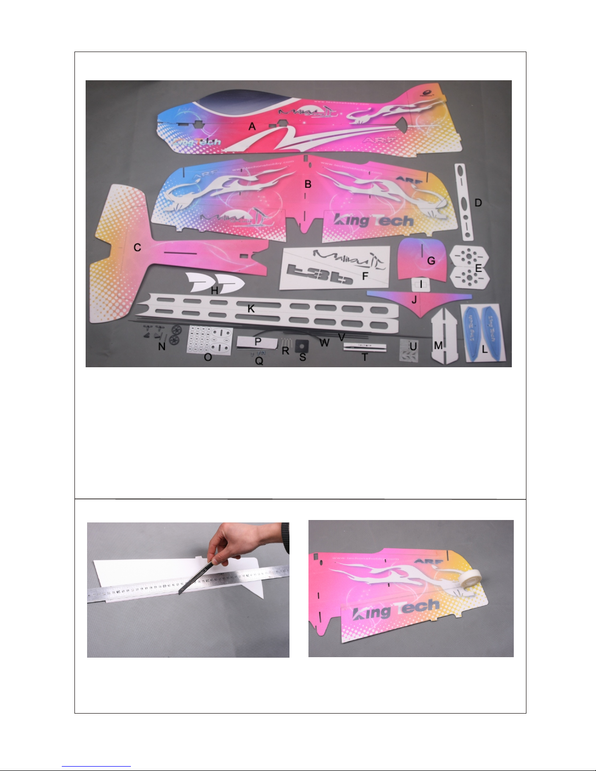
Kit Contents
-1-
A Fuselage
B Wing with aileron
C Rear of horizontal fuselage
D Rudder damping board
E Aileron damping board
F Wing strengthen foam with letters (Letters: Malibu, F3P)
G Head of horizontal fuselage
H Wing fences on the wing tip
I Strengthen foam slices around the battery holes
J Landing gear stringers
K Fuselage stringers
L Whe el c overs
M Wing fences u nd er the middle w ing
N Landing gea r se ts
O Doublers
P Velcro
Q Screws
R Z bend
S Motor mount
T Thread
U Servo arms an d co ntrol horns
V Carbon fibe r ro ds and strips
W Shrink tube
1.Cut 45 bev el on the two ailerons.
2.Use 3M magic tape to splice the two ailerons and the wing.
Page 3
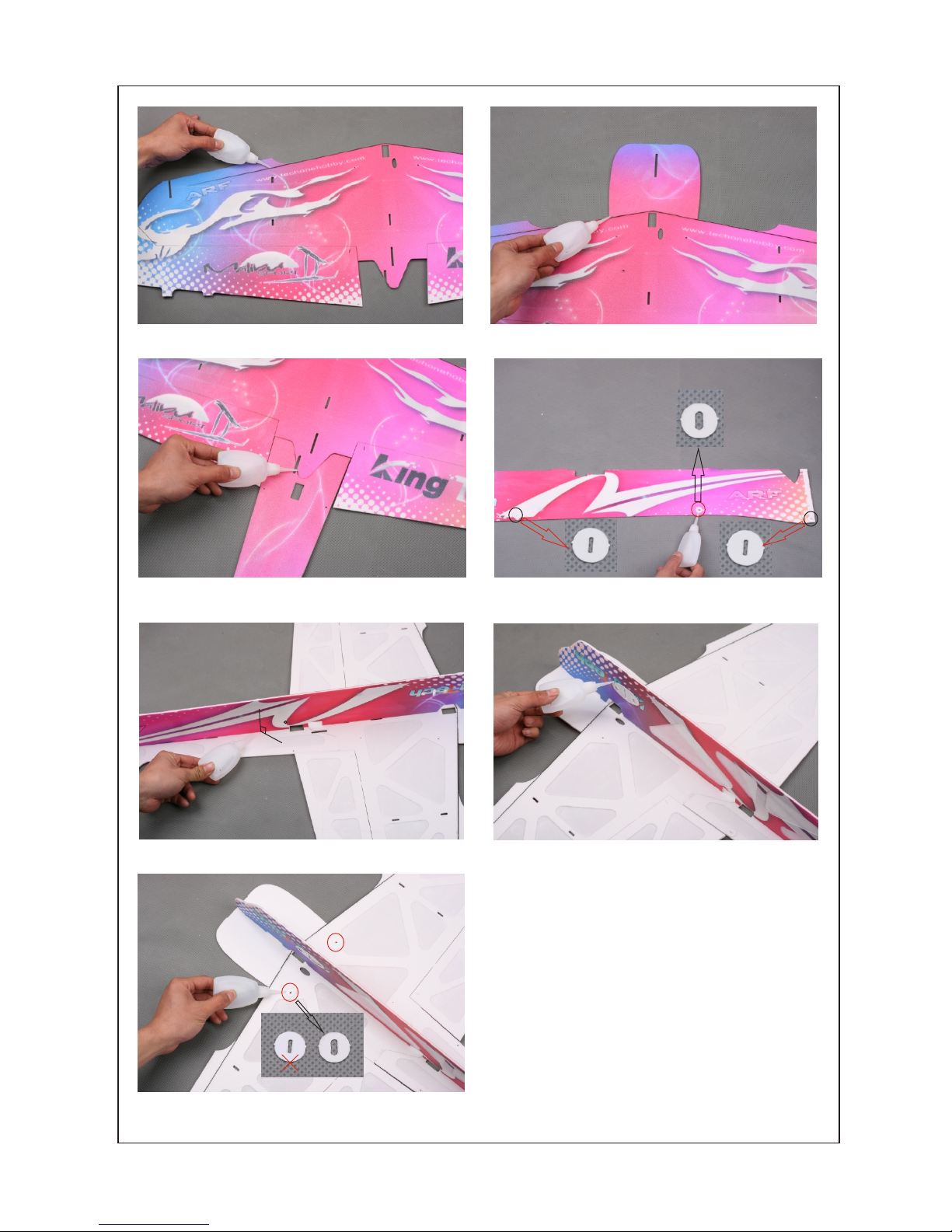
3.Glue 2pcs carbon fiber strips on the front of wing with some
foam-friendly C/A.
4. Use some foam friendly C/A to glue the head of the horizontal
fuselage to the wing, see above picture.
5.Key the rear of horizontal fuselage into the wing and apply
some foam friendly C/A.
7. Fix the lower vertical fuselage to the horizontal fuselage with
some foam friendly C/A. Make sure they’re vertical, no distortion.
8. Install the landing gear reinforcements.
9. Install the round doublers to the pre-reserved holes (2 places)
on the wing forehead to strengthen the joint of carbon fiber rod
and foam.
6.Install the round doublers to the pre-reserved holes (6 places)
on the lower vertical fuselage.
-2-
90
Page 4

17
5
mm
2 0
m
0
m
20
5
m
m
20
0m
m
305mm
300mm
11.Install the round doublers to the
pre-reserved holes (4 places) on the
horizontal stabilizer.
12. Insert the wing fence into the
pre-reserved slot of the middle wing and
apply some foam friendly C/A.
13. Bevel the wing strengthen foam.
10. Install the round doublers to the
pre-reserved holes (2 places) on the
horizontal fuselage.
14.Install the round doublers to the
pre-reserved holes (4 places) on the
wing. Please pay attention to the direction
of the slot on the round doubler, see
above picture for reference.
15.Install the carbon fiber rods (4pcs) to
strengthen the wing as shown.
16.Place the wing strengthen foam
between the two carbon fiber rods.
Note: Please pay attention to the hollowcarved letters on the wing strengthen
foam. Put the foam right side down.
17.Apply some C/A to the round doubler
joints.
18.Apply some C/A to all the joints of
carbon fiber rods and the wing strengthen
foam.
19.Fix the elevator to the fuselage with
3M magic tape.
20.Install other carbon fiber rods.
Finished carbon fiber rods assembly
picture as shown.
21. Install the landing gears.
-3-
Page 5

25. Install the servos.
26. Install the elevator and rudder control horns.
27. Bevel 45 degree the fusealge stringers.
28. Fix the fuselage stringers to the
fuselage. Note: Keep the fuselage and
wing vertical, no distortion.
29. Fix the wheel covers to the wheels with
some C/A.
30. Bevel the landing gear stringers.
31. Fix the landing gear stringers with
some C/A as shown.
32. Glue 1pc straight fiber glass and 1pc original servo arms together. 2 kinds of fiber
glass servo arms, straight servo arm (2pcs) and bended servo arm (1pc).
-4-
Rudder servo
Elevator servo
Aileron servo
90
22. Key the upper vertical fuselage on the
wing with some foam friendly C/A. Be
vertical and no distortion.
23. Fix the rudder to the fuselage with 3M
magic tape.
24. Install the motor mount.
Page 6

35.Insert the aileron control horns into the
pre-reserved slots on the aileron and
apply some C/A to fix it.
36. Push rod assembly: Put the longer
end of the “Z” bend into the shrink tube
and then overlap one end of the carbon
firber rod as shown in the picture, then use
a heat gun to shrink the tube.
(For ai leron )
40.Cut a 40mm long carbon fiber strip and a 20mm slot on the bottom vertical fuselage
as shown. Insert the strip into the slot, then apply some C/A to fix it. The strip is used as a
tail skid.
38.Link the servos and rudder control
horns with threads. Make sure the threads
are taut and the two ends of the servo
arms are tied with threads.
39.Link the servos and elevator control horns with threads. Make sure the threads are taut and the two ends of the servo arms are tied
with threads.
37.Install aileron carbon fiber rods.
41.Install the motor.
-5-
33.Glue 1pc bended fiber glass and 1pc original servo arms together.(for aileron)
34. Glue together the contron horns and
their backplates. (for aileron)
Page 7

45.Place the strengthen foam slices around the pre-reserved
battery hole and use some foam friendly C/A to fix. Then insert
the battery into the battery hole.
42.Insert the wing fence into the pre-reserved slot on the wing
tip, then apply some foam friendly C/A to fix it.
43.Insert the aileron damping board into pre-reserved place,
then apply some foam friendly C/A to fix it.
44.Install the rudder damping board. Same assembly as the
aileron damping board.
-6-
47.Install the receiver.
48.Insta ll the pr opell er.
46.Install the ESC with velcro.
ESC
Page 8

Seek Assistance
If you are new to R/C we suggest you find an experienced pilot to check out your aircraft and help you with
the first few flights.This will help prevent damage to your model and will speed up the learning process
and making your R/C experience all the more enjoyable. You can contact local R/C clubs or your dealer
to obtain the names of experienced R/C pilots who would be w illingto help you with your first few flights.
Although this is an ARF (Almost-Ready-to-Fly) kit, it does have some construction features that can be
challenging to the less experienced modeler. If you encounter difficulty in any construction sequence,
please feel free to contact one of our technicians, we stand ready to provide any assistance we can.
Contact us at:
E-Mail: techonehobby@gmail.com
Copyright 2010 Techonehobby
Http://www.techonehobby.com
TM
C
Balance Point
The Center of Gravity (C/G or Balance Point) is 80mm(3.15")
from the leading edge of the wing, measured at the center of the
wing.
WARNING For test flying and general sport flying, we suggest you
balance the airplane at the C/G recommended above. For 3D
flying, you may want to experiment moving the C/G back in small
increments until you're satisfied with the result.
Control thr ow s
Sport Flyin g
Ailerons: ( 26. 4m m) 1.0 4" Up and Down
Elevator: ( 24. 8m m) 0.9 8" Up and Down
Rudder: (3 7. 2mm) 1.46" Right and Left
3D Flying
Ailerons: (72.6mm)2.86" Up a nd Down
Elevator: (74.4mm)2.93" Up and Down
Rudder: (111.6mm)4.40" Ri ght and Left
The control throws are measured from the widest point of
the control surfaces
Exponenti al
Sport Flyin g
Ailerons: 2 0%
Elevator: 2 0%
Rudder: 20%
3D Flying
Ailerons: 4 5% - 5 5%
Elevator: 4 5% - 6 0%
Rudder: 45% - 6 0%
Exponenti al s oftens the re sponse of the c on trol surfac es
around neut ra l stick. Th is makes the ai rplane easier t o
control whi le u sing such lar ge control thro ws. The
Exponenti al v alues shown a re given as a perce nt. Please
note that different br an ds of radio con trol systems ma y call
for + or - Expo. Pl ea se check your t ransmitte r' s owners
manual for mo re i nfo.
Motor Thrust
To ensure great flight performance and to be able
to trim your airplane properly, it is critical that you
adjust the motor thrust as described. We suggest
that you add 2 degrees of down-thrust and 1
degrees of right-thrust. This can be achieved by
adding a washer or two behind the top and right
side of the motor (between the motor and the
firewall). When set properly, the trim for the
elevator and the rudder should be neutral. Finetune the down-thrust and right-thrust until this trim
is achieved.
Made in China
-7-
C/G
 Loading...