

Page 1
Warning
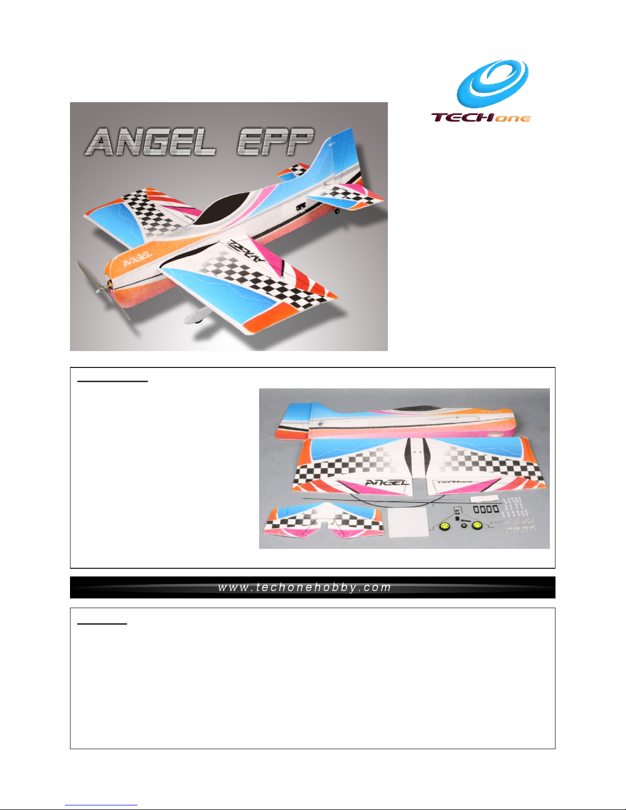
1.Fuselage 1
2. Wing 1
3.Ailerons 2
.
. levator 1
.
.Landing Gea r
. heel Cover(E PP ) 1
. heel hocks 4
10.Tailing whe el 1
11. Co nt ro l Horns 4
12.Clevis 8
13. Servo Mount 4
1 .
1 .Carbon Rod . * mm
16.Steel Wir e 0. 8* 360mm 1
17.Heat-Sh ri nk Tu bing ¢1.5*400 mm 1
1 .
4 Horizontal St ab il izer 1
5 E
6 Rudder 1
7 1
8 W
5 1 3 700 2
8 Velcro 1
19.
9 W C (plywood)
(plywood)
4 Hinges 15
Wood Screws - 4
Kit Co ntents
1. EPP Electric R\C m odel is not a toy and is not suitab le for the flyer under 14 years .
2.Do not f ly near houses or buildin gs childre n' s play areas road tra ffic r ailways airports, overh ead
power li nes and pylons. Do not fly ov er p eople.
3.
4. .
5.Do not f ly in the strong winds.
6.Do not t ry to catch the plane by hand whe n it is flying.
7.The ch ildren who are younger th an 1 4 years old should be assis te d by an experienced adult w hen
the plan e is being flown.
ANGEL- If
misuse d, it can cause serious bod il y harm and damage to proper ty.
, , ,
Fly only i n open areas, preferabl y AMA (A cademy of Model Aeronaut ic s) approved flying site s,
follow ing all instructions in cl uded with your radio.
Assemb le the kit according to the seq uence provided in the ins tr uction manual
Before use,please read the explanations carefully!
TM
Flying environment
In-door:L arge hall or gymnasium
Out- door: Windless dawn or dusk
Instruction Manual
Instruction Manual
Specifications
985mm (38.8 in.)
900mm (35.4 in.)
Brushless outrunn er M ot or
30A Brushless ESC
1060 Slow Flyer Prop
8
3 Cells 11.1V 10 00 mA h Li-po
Fuselage length:
Wingspan:
Flying Weig ht : 40 0- 420g (with b at te ry)
Motor: 2212
ESC:
Propeller:
Servo: g
Radio:4/ mo re c ha nnel
Receiver:4/m or e channel
Battery:
Page 2
5
, -cut
on elevator
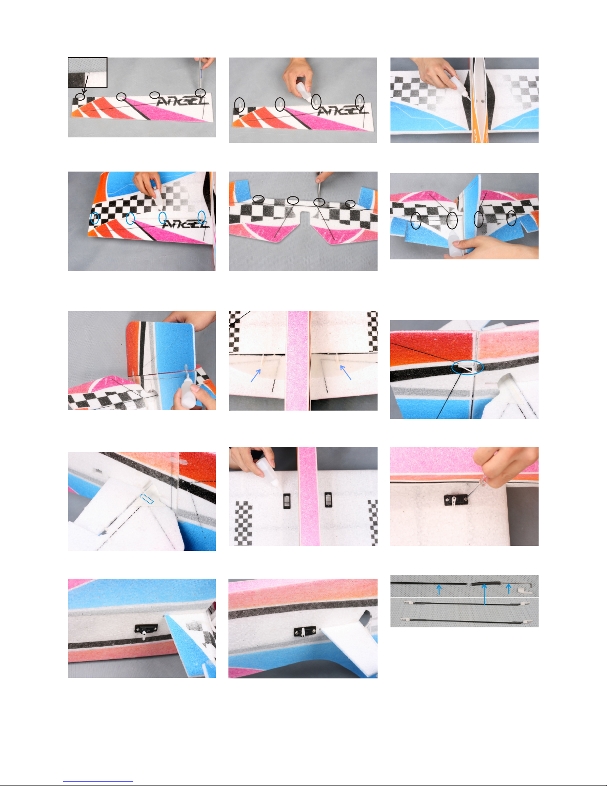
.Cut four slot s wh er e the hinges
will be installed we h av e pr e
the .
6. Insert the e le va tor and the
horizontal into the
fuselage Hinge the ele va to r to the
horizontal , using the same
techniques that you u se d to h inge
the ileron to the wing.
stabilizer
stabilizer
.
a
8. . Install the ilerons co nt rol horna
10. . Insta ll t he e levator control hor n
11. Gl ue se rv o
servo
the mount to the
wing Please align them w it h th e
holes on the wing.
.
1.
, -cut on
ileron
Cut four slots where th e hi ng es
will be installed we h av e pr e
the a .
2. Insert the h in ge s into the ,
then glue the cut
slots
.
3. Insert the w in g in to the fuselage.
Center the wing and glu e it t o th e
fuselage.
4. the same on wing,
h ileron tight
against the wing, ins er t th e hinges
into the , and glue the cut
Cut slots the
a
slots .
While olding the
7 rudder vertical
stabilizer
.Hinge the to the
, using the same
techniques that you u se d to h inge
the ileron to the wing.a
9 Install the rud de r co ntrol horn. .
12.Install t he i le ro n into the
mount using the screws
provided with the ser vo .
a servo
servo
13.Install t he ru dd er mo unt
and the using the same
techniques that you u se d to I nstall
the ileron .
servo
servo
servoa
14.Install t he el ev ator mount
and the using the same
techniques that you u se d to I nstall
the ileron .
servo
servo
servoa
15 L
, then
L
L
. A
L
,
L
.
.First you sho ul d ma ke the -
bend as shown hold the h ea t
shrink tubing that co nn ec ts the
pushrod to the L-b en d and gently
rotating the -b en d un til the glue
holding the - bend i n pl ac e has
broken loose djust the length by
pulling or pushing th e -bend until
the appropriate len gt h is a chieved
and re-glue th e -bend to the
pushrod using some CA gl ue
Steel W ire
Heat- Shr ink Tubi ng
Carbo n Rod
Page 3

16 L
Finish the servo inst al la tion by placing the ser vo a rm an d re in stalling the servo sc re w
.Thread a L-b end through the contr ol h or n. And thread the other -b en d onto the outer most hol e of t he s ervo
arm. onto the se rv o .
21.Cut a slot on the bo tt om f uselage
as shown.
23.I the the
i t to the fuselage.
nsert tailing wheel into
slot and glue
28 Cut 3pcs velcr o, t he n fix them
inside the cockpit as s ho wn i n above
picture
.
.
25 I . nstall the and pro pe ll er onto the
motor.
17.Install t he t wo w heels and wheel
chocks. Keep 1mm dist an ce
between wheel and its c ho ck . Apply
some C/A to glue the chock s.
18.Glue the tw o wh ee l cover pieces
together.
19.Slide one w he el c over onto each
axle and up against the w he el s.
Align the wheel cover s, t he n glue
them securely to the ax le s. An d
insert the landing ge ar i nt o the slot
of the bottom fuselag e.
20.Cut 2pcs ca rb on r ods.Place one end of ea ch r od i nto the fuselage and
the other end of the rod in to t he h orizontal stabili ze r an d glue it.
24.Install t he mo to r
into the motor mount
using the screws
provided with the
motor.
26.I the ESC.nstall
27.Install t he r ec eiver and battery
into the cockpit, usi ng a p ie ce of
v .elcro
ESC
Battery
Receiv er
22.Glue the ta il in g wheel pieces
together.
Page 4

Seek Assistance
If you are new to R/C we suggest you find an experienced pilot to check out your aircraft and help you with the first
few flights. This will help prevent damage to your model and will speed up the learning process and making your
R/C experience all the more enjoyable. You can contact local R/C clubs or your dealer to obtain the names of
experienced R/C pilots who would be w illing to help you with your first few flights.
Although this is an it does have some construction features that can be challenging
to the less experienced modeler. If you encounter difficulty in any construction sequence, please feel free to
contact one of our technicians , we stand ready to provide any assistance we can. Contact us at:
E-Mail: techonehobby@gmail.com
ARF (Almost-Ready-to-Fly) kit,
The Center of Gravity (C/G or Balance Point) is 3.2” (82mm)
from the leading edge of the wing, measured at the center of
the wing.
WAR NI NG For test flying and gene ra l sp ort flying, we
suggest you balance t he a ir plane at the C/G
recommended above . Fo r 3D f lying, you may want to
experiment moving t he C /G b ack in small incremen ts u nt il
you're satisfied wi th t he r esult.
Control throws
Sport Flying
Ailerons: (32.8mm)1.29" Up an d Do wn
Elevator: (22.8mm)0.90" Up an d Do wn
Rudder: (45.2mm)1.78" Right a nd Left
3D Flying
Ailerons: (82mm)3.23" Up and D own
Elevator: (57mm)2.24" Up an d Do wn
R udder: (113mm)4.45" Righ t an d Left
The control throws are measured from the widest point of
the control surfaces
Exponential
Sport Flying
Ailerons: 20%
Elevator: 20%
Rudder: 20%
3D Flying
Ailerons: 35% - 50%
Elevator: 35% - 50%
R udder: 35% - 50%
Exponential softe ns t he r esponse of the contro l su rf aces
around neutral stic k. This makes the air pl an e easier to
control while using s uc h la rge control throws. The
Exponential value s sh ow n are given as a percent. P le as e
note that diffe re nt brands of radio cont ro l sy stems may
call for + or - Expo. Pleas e ch ec k your transmitter' s
owners manual for mor e in fo .
Balance Point
TM
Copyright 2009 Techonehobby
Http://www.techonehobby.com
C
MADE IN CHINA
Motor Thrust
To ensure gr eat flight performanc e an d to
be able to t rim your airplane prope rl y, it is
critic al that you adjust the motor th rust as
descri bed. We su ggest that you add 2
degree s of down-thrust and 1 degr ee s of
right- thrust. Th is can be achieved by addin g
a washer o r two behind the top and righ t
side of th e motor (between the motor an d
the fire wall). When set properl y, the trim for
the elev ator and the rudder shoul d be
neutra l. Fine-tune the down-t hr ust and
right- thrust until this trim is ach ieved.
C/ G
 Loading...