

Page 1
Specifications
Fusel age len gth: 850mm (33. 5i n)
Wings pan: 800mm (31. 5i n)
Flyin g Weigh t: 150- 180g( with b atter y)
Instruction Manual
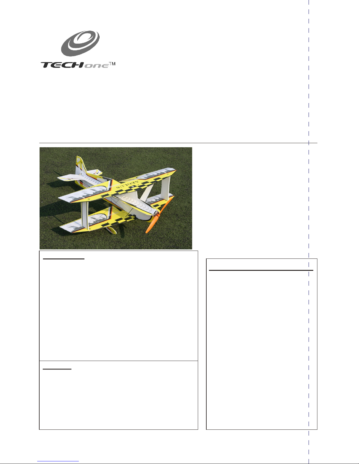
AEOLUS F3PAEOLUS F3P
Before use,please read the explanations carefully!
lLaser-cut 3mm genuine EPS parts for optimum stre ngth an d
Minim um weig ht .
lLightweight carbon fiber truss system virtually eliminates flex .
lIdeal for indoor flight and capable of outdoor flight in low winds.
lMinimal assembly required flight ready in as little as 3 hours .
lVibrant screen printed trim scheme.
Warning
An R/C aircraft is not a toy! If misused, it can cause seriousbodily harm and
damage to property. Fly only in open areas,preferably AMA (Academy of
Model Aeronautics) approved flying sites, following all instructions included
with your radio.Always assume the electric motor can come on at any time
souse extreme caution.Before beginning assembly of your ,
we strongly uggest that you read through this instruction manual so you
canbecome familiar with the parts and the assembly sequence.Assemble the
kit according to the sequence provided in the instruction manual. Do not
attempt to modify or change the kit design as doing so could adversely
change the models flying characteristics.
AEOLU S-F3P
s
Additional Required Equipment
Motor: 2404 KV:1600
ESC: 10 A
GWS 8040
Radio 4 m ore cha nnel
Recei ver 4 mor e chann el
Batte ry char ger
7.4V mAh
Prope ller: -905 0 Slow Fl yer Pro p
Servo :5G* 3
: /
: /
Batte ry: 350- 500
Introduction
Thank you for purchasing the AEOLUS-F3P.
The AEO LUS-F 3P ARF has super slow flight responsiveness so you can fly
high-alpha 3D with authority. Its carbon fiber reinforced AEOL US-F3 P
construction provides the solid, precise feel of a balsa profile plane without the
weight. This allows you to fly the AEOLUS -F3P ARF outside in windier
conditions that would keep most other profile foamies grounded. The AE OLUSF3P ARF is another exciting addition to TECH ONE's outstanding line of electric
RC aircraft and accessories.
TECH ONE uses top-quality engineering and materials in everything it makes, so
you always get the maximum level of value and fun. TECH ONE backs all of its
products with the best customer service and support in the hobby so your electric
flight experience is always a positive one.
These assembly instructions are designed to guide you through the entire
assembly process of your new airplane in the least amount of time possible. Along
the way you'll learn how to properly assemble your new airplane and also learn
tips that will help you in the future. We have listed some of our recommendations
below. Please read through them before beginning assembly.
Required Tools and Adhesives (not included in the kit)
5 Minute Epoxy
Glue
Aerosol Zip-Kicker
# 0 and #1 Phillips Head Screwdrivers
1.5mm Hex Wrench
Adjustable Wrench
Wire Cutters
Z-Bend Pliers
Needle Nose Pliers
Modeling Knife
Scissors
Electric or Hand Drill
Assorted Drill Bits
Straight Edge Ruler
Pencil
T-Pins
Builder's Triangle
220 Grit Sandpaper with Sanding Block
Masking Tape
Paper Towels
Rubbing Alcohol
Epoxy Mixing Sticks
Epoxy Mixing Cups
Soldering Iron
Page 2
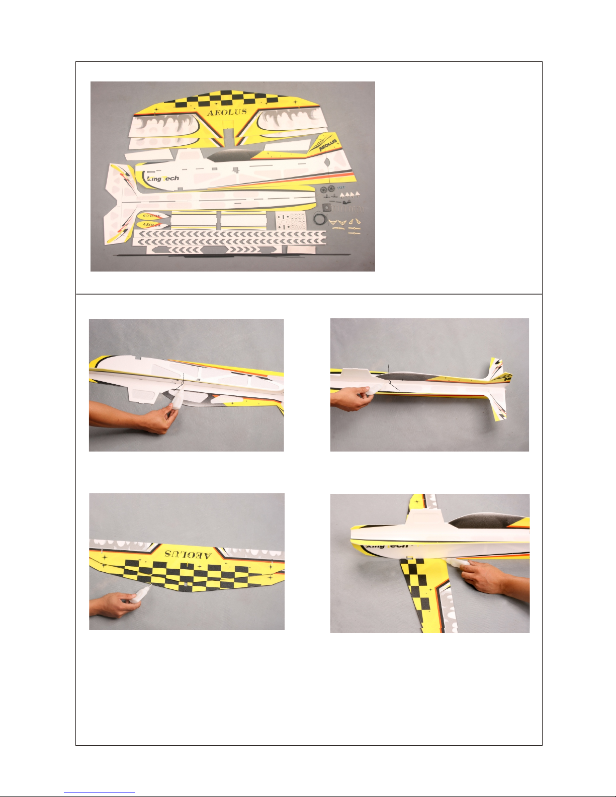
Kit Contents
Fuselage and Wing Assembly
-1-
1.
Glue 2p cs carb on stri ps on the f ront of t he wing s with
some fo am-fr iendl y C/A.
A
B
C
D
E
F
G
H
I
J
K
L
M
N
O
P
Q
R
90
Glue th e fusel age sid e board t o main bo ard wit h foam-friendl y C/A.
Note: N o disto rtion o f the fus elage
Use foa m-fri endly C /A to glue t he lowe r wing to t he
fusel age. No te: The l ower wi ng shou ld be
beper pendi cular t o the fus elage .
S
A Upper an d Lower W ings wi th Ailer on
B Fusel age Mai n Board
C Fusel age Sid e Board
D Wing Fe nces
E Wheel C overs
F Fusel age Str inger s
G Carbo n Fiber R ods
H Velcro
I Threa ds
J Landi ng Gear S tiffe ners an d Round
Doubl ers
K Eleva tor and R udder C ontro l Horns
L Aile ron Con trol Ho rns
M Servo Ar ms
N Z Bend
O Motor M ount
P Landi ng Gear s
Q Ailero n Contr ol Horn s
R Motor S crews
S Wing St rengt henin g Foam St rip
90
Page 3
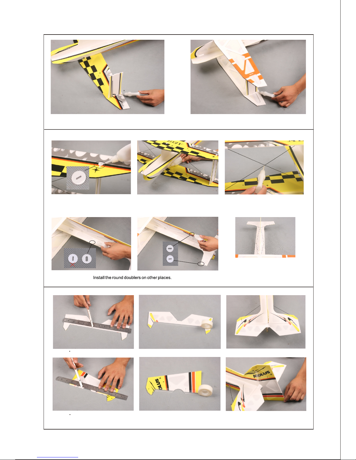
-2-
90
Bracing
Cut proper length of carbon fiber rods,
then install them into corresponding
round doublers. Note: The fuselage side
board should be perpendicular to the
fuselage main board.
2.
3. Others Assembly
Fix the w ing fen ces on th e lower w ing wit h some
foam- frien dly C/A .
Fix the u pper wi ng and th e wing fe nces to gethe r with
foam- frien dly C/A .
Insta ll the ro und dou blers o nto the
pre-r eserv ed hole s on uppe r and low er
wings t o stren gthen t he join t of carb on
fiber r ods and f oam.
Insta ll the ca rber fi ber rod s as show n
to stre ngthe n the fus elage a nd wing s.
Apply s ome foa m-fri endly C /A on the
inter secti on of the t wo carb er fibe r
rods an d fix.
Cut a 45 be vel on th e eleva tor as sh own.
Cut a 45 be vel on th e eleva tor as sh own.
Fix the e levat or and ho rizon tal sta biliz er with 3 M magic tape.
Fix the r udder a nd fuse lage wi th 3M mag ic tape .
1
4
5
mm
1
4 m
m5
20
0
m
m
Page 4

-3-
Cut 45 be vel on th e four ai leron s.
Use 3M ma gic tap e to spli ce the fo ur aile rons an d the upp er and
lower w ings.
Glue th e ailer on horn s onto th e upper a nd lower
ailer ons wit h some fo am-fr iendl y C/A.
Attac h the inc luded z -bend s to the su itabl e lengt h of carbon
fiber p ushro d using h eat shr ink tub e. Use a so ldering iron
or heat g un to shr ink the p ushro d to the z- bend.
Insta ll the mo tor mou nt.
Cut a 45 be vel as sh own.
Cut a 45 be vel as sh own.
Glue th e fusel age str inger s onto th e sides o f the fus elage .
Cut the b oth end s of the fo am stri ps as 45 be vel.
Glue su itabl e lengt h of carb on fibe r strip t o the
front o f the foa m strip a s show, th en atta ch the
foam st rips to t he uppe r wing an d fusel age and
fix the m with fo am-fr iendl y C/A.
170mm
Page 5

-4-
4. Landing Gear
Glue together the contron horns
and their backplates.
Aileron carbon fiber push rods wit h
Z bend.
Assem ble the l andin g gears a nd fix th em with s ome
foam- frien dly C/A .
Insta ll the la nding g ear sti ffene rs.
Insta ll the la nding g ear sti ffene rs.
Insta ll the la nding g ears wi th some
foam- frien dly C/A .
Fix the w heel co vers wi th some
foam- frien dly C/A .
5. C ontrol Horns and Servos
Glue th e anti- diffe renti al arm to t he serv o if you wa nt to ext end the
lengt h of the se rvo arm .
Fix the a ilero n contr ol horn s with
some C/ A.
Cut a 40mm long carbon fiber strip and a 20mm slot on the bottom vertical fuselage as shown.
Insert the strip into the slot, then apply some C/A to fix it. The strip is used as a tail skid.
Page 6

-5-
Insta l the pus h rods to c onnec t the ail eron se rvos an d
contr ol horn s.
Fix the e levat or cont rol hor ns with s ome C/A .
Fix the r udder c ontro l horns w ith som e C/A.
Page 7

-6-
6. Control System
Link th e servo s and con trol ho rns wit h threa ds, mak e sure th e threads a re taut a nd
the two e nds of th e servo a rms are t ied wit h threa ds.
Mount y our ESC t o the fus elage , using o ne piec e of velc ro.
Insta ll the mo tor
Insta ll the ba ttery i nto the
pre-r eserv ed plac e on the he ad of
plane a s shown .
Use one p iece of v elcro t o fix you r
recei ver on th e fusel age.
PRO TIP: After flying the airplane, you may want
to add right and/or down thrust to the motor. You
can do this by adding thin washers between the
motor mount and the firewall.
Page 8

Seek Assistance
If you are new to R/C we suggest you find an experienced pilot to check out your aircraft and help you with
the first few flights.This will help prevent damage to your model and will speed up the learning process
and making your R/C experience all the more enjoyable. You can contact local R/C clubs or your dealer
to obtain the names of experienced R/C pilots who would be willingto help you with your first few flights.
Although this is an ARF (Almost-Ready-to-Fly) kit, it does have some construction features that can be
challenging to the less experienced modeler. If you encounter difficulty in any construction sequence,
please feel free to contact one of our technicians, we stand ready to provide any assistance we can.
Contact us at:
E-Mail: techonehobby@gmail.com
Copyright 2009 Techonehobby
Http://www.techonehobby.com
TM
C
Balance Point
The Center of Gravity (C/G or Balance Point) is 2.3 6" (60mm)
from the leading edge of the wing, measured at the center of
the wing.
WARNING For test flying and general sport flying, we suggest
you balance the airplane at the C/G recommended above. For
3D flying, you may want to experiment moving the C/G back in
small increments until you're satisfied with the result.
Control thr ow s
Sport Flyin g
Ailerons: 2 8m m( 1.10" ) Up and Down
Elevator: 2 2m m( 0.87" ) Up and Down
Rudder: 36m m( 1.4 2" ) Ri ght and Left
3D Flying
Ailerons: 7 7m m( 3.03" ) Up and Down
Elevator: 6 6m m( 2.60" ) Up and Down
Rudder: 108 mm (4. 25")R ight and Left
The control t hr ows are measu red from the wide st
point of the co nt rol surface s
Exponenti al
Sport Flyin g
Ailerons: 2 0%
Elevator: 2 0%
Rudder: 20%
3D Flying
Ailerons: 4 5% - 5 5%
Elevator: 4 5% - 6 0%
Rudder: 45% - 6 0%
Exponenti al s oftens the re sponse of the c on trol
surfaces ar ou nd neutral st ick. This m akes the airpla ne
easier to con tr ol while usin g such large cont rol throws.
The Exponen ti al values sho wn are given as a per cent.
Please note t ha t diffe re nt brands of ra dio control
systems may c al l for + or - Expo. Pl ease check yo ur
transmitt er 's owners man ual for more in fo .
-7-
Motor Thrust
To ensure great flight performance and to be able
to trim your airplane properly, it is critical that you
adjust the motor thrust as described. We suggest
that you add 2 degrees of down-thrust and 1
degrees of right-thrust. This can be achieved by
adding a washer or two behind the top and right
side of the motor (between the motor and the
firewall). When set properly, the trim for the
elevator and the rudder should be neutral. Finetune the down-thrust and right-thrust until this trim
is achieved.
Made in China
 Loading...