

Technoware EVO DSP PLUS TT 100 KVA, EVO DSP PLUS TT 160 KVA, EVO DSP PLUS TT 200 KVA, EVO DSP PLUS TT 120 KVA User Manual
Uninterruptible Power Supply
EVO DSP PLUS TT 100 KVA
EVO DSP PLUS TT 120 KVA
EVO DSP PLUS TT 160 KVA
EVO DSP PLUS TT 200 KVA
User’s manual
Manuale utente


Index
User’s Manual - English ...............................................................................1
Safety Warnings ........................................................................................1
1 Introduction ........................................................................................2
2 General Characteristics ..........................................................................3
3 Receipt and site selection .......................................................................3
3.1 Site Selection ................................................................................ 3
3.2 UPS Unpacking ............................................................................... 4
4 Operational Principles............................................................................5
4.1 Block Diagram of UPS ....................................................................... 5
4.2 Operation Modes ............................................................................. 6
4.2.1 Standby Mode ......................................................................................... 6
4.2.2 Line Mode .............................................................................................. 7
4.2.3 Battery Mode .......................................................................................... 7
4.2.4 Bypass Mode ........................................................................................... 8
4.2.5 ECO Mode .............................................................................................. 8
4.2.6 Shutdown Mode ....................................................................................... 9
4.2.7 Maintenance Bypass Mode ........................................................................... 9
5 Control Panel and LCD Touchscreen ........................................................ 10
5.1 Introduction ................................................................................ 10
5.2 LCD Touchscreen Description ............................................................ 11
5.2.1 Initial Screen ........................................................................................ 11
5.2.2 Main Screen (Home) ................................................................................ 11
5.2.3 Control Submenu ................................................................................... 13
5.2.4 Measurement Screen ............................................................................... 14
5.2.5 Setup Screen ........................................................................................ 16
5.2.5.1 Setup General Screen ...................................................................... 20
5.2.5.2 Setup System Screen ....................................................................... 23
5.2.5.3 Setup Battery Screen ....................................................................... 25
5.2.5.4 Setup Pre-Alarm Screen .................................................................... 26
5.2.5.5 Setup Parallel Screen....................................................................... 27
5.2.6 Information Submenu .............................................................................. 28
5.2.6.1 Information–Identification Submenu ..................................................... 28
5.2.6.2 Information–System Submenu ............................................................. 28
5.2.6.3 Information–Battery Submenu ............................................................ 29
5.2.7 Event Submenu ..................................................................................... 30
5.2.7.1 Event-Current Events Submenu .................................................................. 31
5.2.7.2 Event-History Events Submenu ................................................................... 31
5.2.7.3 Event-Reset All Events Submenu ................................................................. 32
5.3 Alarm List ................................................................................... 33
5.4 History Record ............................................................................. 35

6 ELECTRICAL INSTALLATION.................................................................... 36
6.1 Front Side ................................................................................... 36
6.1.1 Power Stage/Module ............................................................................... 36
6.1.2 Interface and Communication .................................................................... 37
6.1.2.1 CN1-Temperature Detection Port for External Battery Pack ........................ 38
6.1.2.2 CN2-EPO (Emergency Power OFF) connector ........................................... 38
6.1.2.3 RS232 and USB Interfaces .................................................................. 39
6.1.2.4 SNMP Interface .............................................................................. 39
6.2 Rear Panel .................................................................................. 40
6.3 Output/input Terminal Blocks ........................................................... 41
6.4 Installation .................................................................................. 42
7 Functioning ....................................................................................... 44
7.1 Turn ON Operation ........................................................................ 44
7.2 Cold Start Startup.......................................................................... 46
7.3 Turn OFF Operation ....................................................................... 47
7.3.1 Turn OFF Operation in Bypass Mode/Standby Mode .......................................... 47
7.3.2 Turn OFF Operation in Line Mode ................................................................ 49
7.3.3 Turn OFF Operation in Battery Mode ............................................................ 50
7.4 Maintenance Bypass (Manual Bypass) Operation ..................................... 50
7.4.1 Transfer to Maintenance Bypass ................................................................. 51
7.4.2 Transfer to UPS Protection ....................................................................... 52
7.5 Low Battery and Automatic Restart ..................................................... 53
7.6 Load Control ................................................................................ 53
7.7 Operating Procedures for Parallel System ............................................. 54
7.7.1 Input and Output Wiring........................................................................... 54
7.7.2 Parallel Setting ..................................................................................... 55
7.7.2.1 Parallel Board for UPS 1 ................................................................... 55
7.7.2.2 Power Stage/Module ID of UPS 2 ......................................................... 55
7.7.2.3 Parallel Board for UPS 2 ................................................................... 56
7.7.3 Parallel Function Setting .......................................................................... 57
7.7.4 Parallel Cable Connection ........................................................................ 57
7.7.5 Parallel System Turn On Procedure ............................................................. 58
8 Technical Characteristics ...................................................................... 59
9 Maintenance ...................................................................................... 61
9.1 UPS Cleaning ............................................................................... 61
9.2 Battery ...................................................................................... 61
9.3 Operator Safety ............................................................................ 61
10 Troubleshooting ................................................................................. 62
Conformity to the European Directives ......................................................... 65
Product Disposal ..................................................................................... 65
Lead Batteries ........................................................................................ 65

Indice
Avvisi di Sicurezza .................................................................................. 67
1 Introduzione ..................................................................................... 68
2 Caratteristiche Generali ....................................................................... 69
3 Ricevimento e Collocazione................................................................... 69
3.1 Scelta della Collocazione ................................................................. 69
3.2 Disimballaggio e Posizionamento ........................................................ 70
4 Principi di Funzionamento .................................................................... 71
4.1 Diagramma a Blocchi dell’UPS ........................................................... 71
4.2 Modi di Funzionamento ................................................................... 72
4.2.1 Modo Standby ....................................................................................... 72
4.2.2 Modo Line ............................................................................................ 73
4.2.3 Modo Battery ........................................................................................ 73
4.2.4 Modo Bypass ......................................................................................... 74
4.2.5 Modo ECO ............................................................................................ 74
4.2.6 Modo Shutdown ..................................................................................... 75
4.2.7 Modo Maintenance Bypass ......................................................................... 75
5 Pannello di Controllo e Touchscreen LCD .................................................. 76
5.1 Introduzione ................................................................................ 76
5.2 Descrizione dell’LCD Touchscreen ...................................................... 77
5.2.1 Schermata Iniziale .................................................................................. 77
5.2.2 Schermata Principale (Home) .................................................................... 77
5.2.3 Sottomenu “Control” .............................................................................. 79
5.2.4 Schermata “Measurement” ....................................................................... 80
5.2.5 Schermata “Setup” ................................................................................. 82
5.2.5.1 Schermata “Setup-General” ............................................................... 86
5.2.5.2 Schermata “Setup-System” ................................................................ 89
5.2.5.3 Schermata “Setup-Battery” ............................................................... 91
5.2.5.4 Schermata “Setup-Pre-Alarm” ............................................................ 92
5.2.5.5 Schermata “Setup-Parallel” ............................................................... 93
5.2.6 Sottomenu “Information” ......................................................................... 94
5.2.6.1 Sottomenu “Information–Identification” ................................................ 94
5.2.6.2 Sottomenu “Information–System” ........................................................ 94
5.2.6.3 Sottomenu “Information-Battery” ....................................................... 95
5.2.7 Sottomenu “Event” ................................................................................ 96
5.2.7.1 Sottomenu “Event-Current Events” ...................................................... 97
5.2.7.2 Sottomenu “Event-History Events” ...................................................... 97
5.2.7.3 Sottomenu “Event-Reset All Events” .................................................... 98
5.3 Lista Messaggi di Allarme ................................................................. 99
5.4 Altre Segnalazioni nella “History Events”............................................. 101

6 INSTALLAZIONE ELETTRICA .................................................................. 102
6.1 Lato Frontale .............................................................................. 102
6.1.1 Stadi/Moduli di Potenza .......................................................................... 102
6.1.2 Porte di Comunicazione e Interfacce .......................................................... 103
6.1.2.1 CN1-Porta per Rilevamento Temperatura della Batteria Esterna .................. 104
6.1.2.2 CN2–Connettore EPO (Emergency Power Off) ......................................... 104
6.1.2.3 Interfacce RS232 e USB ................................................................... 105
6.1.2.4 Interfaccia SNMP ........................................................................... 105
6.2 Retro UPS .................................................................................. 106
6.3 Morsettiere Output/Input ............................................................... 107
6.4 Installazione Elettrica .................................................................... 108
7 Funzionamento ................................................................................ 110
7.1 Procedura di Accensione................................................................. 110
7.2 Accensione Cold Start .................................................................... 112
7.3 Procedura di Spegnimento .............................................................. 113
7.3.1 Spegnimento in Modo Bypass/Modo Standby .................................................. 113
7.3.2 Spegnimento in Modo Line ....................................................................... 115
7.3.3 Spegnimento in Modo Battery ................................................................... 116
7.4 Operazioni di Maintenance Bypass (Bypass Manuale) ............................... 116
7.4.1 Trasferimento a Maintenance Bypass .......................................................... 117
7.4.2 Trasferimento a Funzionamento UPS........................................................... 118
7.5 Fine Autonomia e Riaccensione Automatica .......................................... 119
7.6 Controllo del Carico ...................................................................... 119
7.7 Procedure Operative per Sistemi Parallelo ........................................... 120
7.7.1 Collegamenti Input/Output ...................................................................... 120
7.7.2 Impostazioni per Parallelo ....................................................................... 121
7.7.2.1 Scheda Parallelo dell’UPS 1 .............................................................. 121
7.7.2.2 Numero ID degli Stadi/Moduli di Potenza dell’UPS 2 ................................. 121
7.7.2.3 Scheda Parallelo dell’UPS 2 .............................................................. 122
7.7.3 Impostazioni per il Funzionamento Parallelo ................................................. 123
7.7.4 Collegamento dei Cavi Parallelo ................................................................ 123
7.7.5 Procedura Accensione del Sistema Parallelo .................................................. 124
8 Caratteristiche Tecniche..................................................................... 125
9 Manutenzione .................................................................................. 127
9.1 Pulizia dell’UPS ........................................................................... 127
9.2 Batterie .................................................................................... 127
9.3 Sicurezza dell’Operatore ................................................................ 127
10 Anomalie ed Interventi ....................................................................... 128
Conformità alle Direttive Europee ............................................................. 131
Smaltimento del Prodotto ....................................................................... 131
Batterie al Piombo ................................................................................ 131
ENGLISH
UPS EVO DSP PLUS TT 1 User’s manual
User’s Manual - English
Safety Warnings
Read this manual carefully and completely before installing and using the TECNOWARE EVO
DSP PLUS TT Uninterruptible Power Supply, which, from here after, will also be referred to as
UPS.
The UPS must be used only by properly trained personnel. To ensure correct and safe
operations, it is necessary that operators and maintenance personnel observe the general
safety Standards as well as the specific instructions included in this manual.
Risk of electric shock: do not remove the cover. The UPS contains internal parts which are at
a high Voltage and are potentially dangerous, capable of causing injury or death by electric
shock.
There are no internal parts in the UPS which are user serviceable. Any repair or maintenance
work must be performed exclusively by qualified technical personnel authorized by
TECNOWARE. TECNOWARE declines any responsibility if this warning is disregarded.
The electric installation has to be done by qualified personnel. Follow all the Safety Standards
(CEI Standards in Italy or IEEE elsewhere) for the Input/Output connections and for the right
section of Input/Output cables.
It is compulsory to ground the UPS according to Safety Standards.
Risk of electric shock at the Output lines when the UPS is ON.
Risk of electric shock at the Output lines while the unit is connected to the AC utility line.
For respect of the Safety Standards is necessary the presence of a differential circuit breaker
between UPS Output lines and the loads.
We recommend to use a dedicate AC Input/Output power line for the UPS.
Do not obstruct ventilation slots or holes and do not rest any object on top of the UPS.
Do not insert objects or pour liquids in the ventilation holes.
Install the UPS indoors, in a protected, clean and moisture-free environment.
Do not expose to the direct sun light.
Do not keep liquids, flammable gases or corrosive substances near the UPS.
ENGLISH
User’s manual 2 UPS EVO DSP PLUS TT
1 Introduction
UPS EVO DSP PLUS TT (UPS means Uninterruptible Power Supply) is the result of constant technological research
aimed at obtaining the best performance at the lowest cost.
UPS EVO DSP PLUS TT is an advanced ON-LINE UPS built specifically to protect your computer from any
irregularities in the AC line (for example blackouts, brownouts, over voltages, micro-interruptions), which often
cause damage to hardware and software.
All that is possible because UPS EVO DSP PLUS TT is a Double-Conversion ON-LINE UPS.
Under normal AC line condition UPS EVO DSP PLUS TT provides an automatic Output Voltage regulation from the
Rectifier and Inverter blocks and filters out frequently occurring electrical disturbances (high Voltage transients,
spikes, interferences, etc.), thus protecting the devices connected to its outlets. During a power failure, UPS EVO
DSP PLUS TT continues supplying adequate AC power (with a true sine wave) to all connected devices through
batteries and by its DC/AC converter (Inverter).
UPS EVO DSP PLUS TT protects the devices from accidental overload or Inverter fault by an Automatic Bypass that
directly connects the AC Input line with Output LIne.
UPS EVO DSP PLUS TT models are factory-equipped with RS-232 and USB interfaces, which may be used for notify
to a computer a power failure or a Low Battery condition: this allows automatic data backup during an extended
blackout with the most common operating systems (Windows, Linux, Unix, etc.). Thanks to Interfaces, UPS EVO
DSP PLUS TT can communicate the several made measurements (Input/Output Voltage, batteries, absorption,
Frequency, etc.), and can also be programmed in order to start-up or shutdown automatically at fixed times.
Read this manual carefully before using the UPS EVO DSP PLUS TT; it includes
important safety warnings and useful advices for correct use and installation.
UPS EVO DSP PLUS TT is constantly being developed and improved: consequently, your unit may differ somewhat
from the description contained in this manual.
This manual includes the following models:
UPS EVO DSP PLUS TT 100 KVA
UPS EVO DSP PLUS TT 120 KVA
UPS EVO DSP PLUS TT 160 KVA
UPS EVO DSP PLUS TT 200 KVA
In this manual UPS EVO DSP PLUS TT will simply be referred to as UPS.
EVO DSP PLUS TT models are made from a single unit that contains only the electronic parts. There are not
batteries inside the unit.
Then the UPS must be connected to an external Battery Box to operate properly.

ENGLISH
UPS EVO DSP PLUS TT 3 User’s manual
2 General Characteristics
UPS EVO DSP PLUS TT has all the advanced features, which guarantee maximum reliability and safety:
Double-Conversion ON-LINE Transformerless technology
Power stages/modules architecture (from 3 to 6 power stages/modules in a single UPS)
Output Voltage regulation 1%
Protection from overload and short circuits
Automatic Bypass to protect from accidental overload or Inverter fault
Start-up even under Mains OFF conditions
Automatic protection when Battery is low
Automatic restart, following an automatic shut-down due to Low Battery, once AC utility power comes
back on
Selectable Input Frequency (50/60 Hz)
Touchscreen Graphic LCD for monitoring of the Input and Output Voltages measurements, batteries
Voltage, percentage of load, frequency, alarms, overload, fault, events history and path of energy flow
and for setting all the UPS parameters
Acoustic signals of various kinds indicating alarm situations
SNMP Adapter (optional)
EPO (Emergency Power OFF)
Communication with the computer through RS-232 and USB interfaces
Available extended autonomy by adding external Battery Boxes
Manual Bypass for maintenance
Parallel operating mode up to 2 UPS (optional)
ECO functioning Mode (selectable)
Frequency Converter functioning mode (selectable)
High efficiency
Maximum reliability
Smart design and easy to use
3 Receipt and site selection
3.1 Site Selection
We recommend paying attention to the below points in order to choose a correct placement for your UPS:
The UPS is designed to operate in a protected environment (e.g. offices). We therefore recommend
installing it in a place with very little or no humidity, dust or smoke.
When the UPS is brought from a cold place to a warmer place, humidity in the air may cause
condensation in the UPS. In this case, allow UPS to stand for two hours in the warmer place before
beginning with the installation.
ENGLISH
User’s manual 4 UPS EVO DSP PLUS TT
In all circumstances, see the “Technical Characteristics” chapter for environmental specifications and
check that the selected area meets these criteria.
During normal operation the UPS discharges a minimal amount of heat. So it is necessary to leave at least
30 cm of unobstructed space all around the UPS in order to keep it properly ventilated.
Do not obstruct ventilation holes.
Do not insert objects or pour liquids in the ventilation holes.
Do not rest any object on top of the UPS.
Do not keep liquids, flammable gases or corrosive substances near the unit.
Install the UPS on a properly tiled floor. Avoid the installation on a floor that is not tiled flat.
3.2 UPS Unpacking
Carefully remove the UPS from its packaging, and carry out a meticulous inspection.
We recommend keeping the original packaging in a secure place, in case you need to send the UPS for
maintenance purposes. In case of transport damage, notify the carrier and dealer immediately.
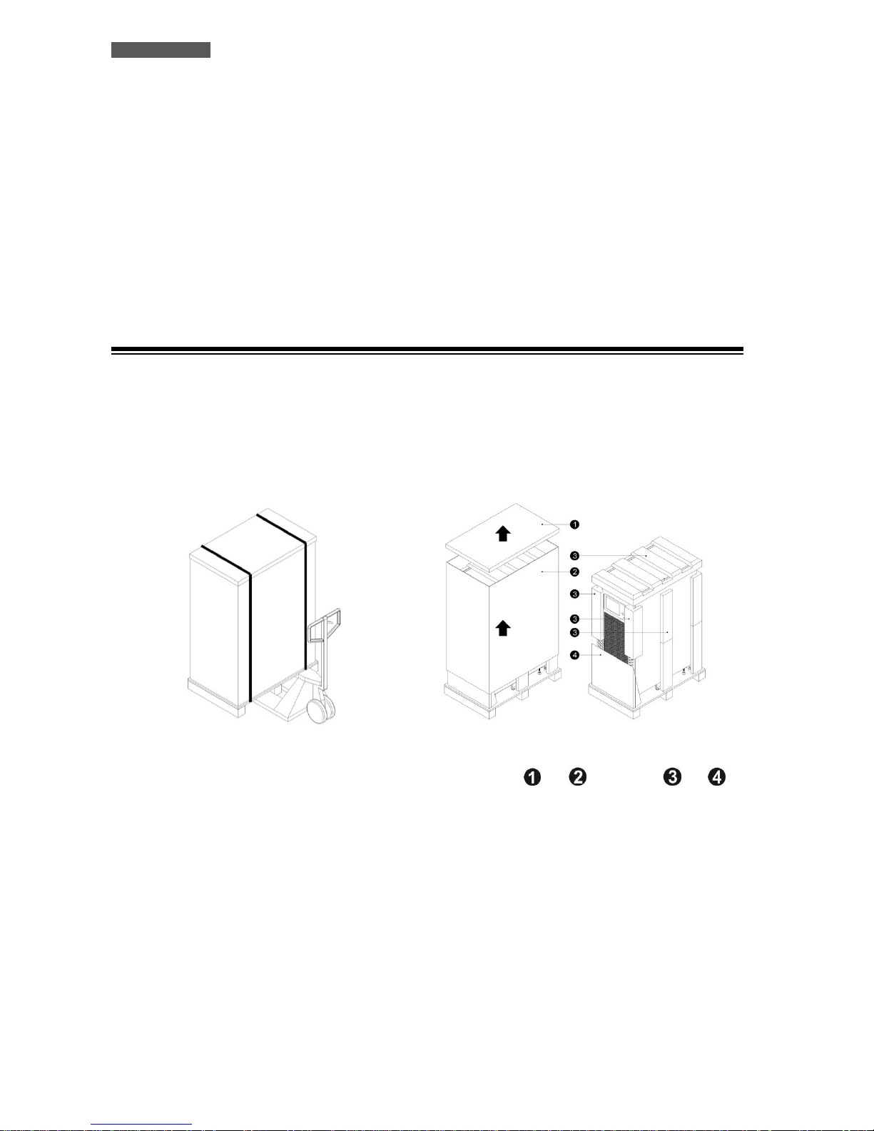
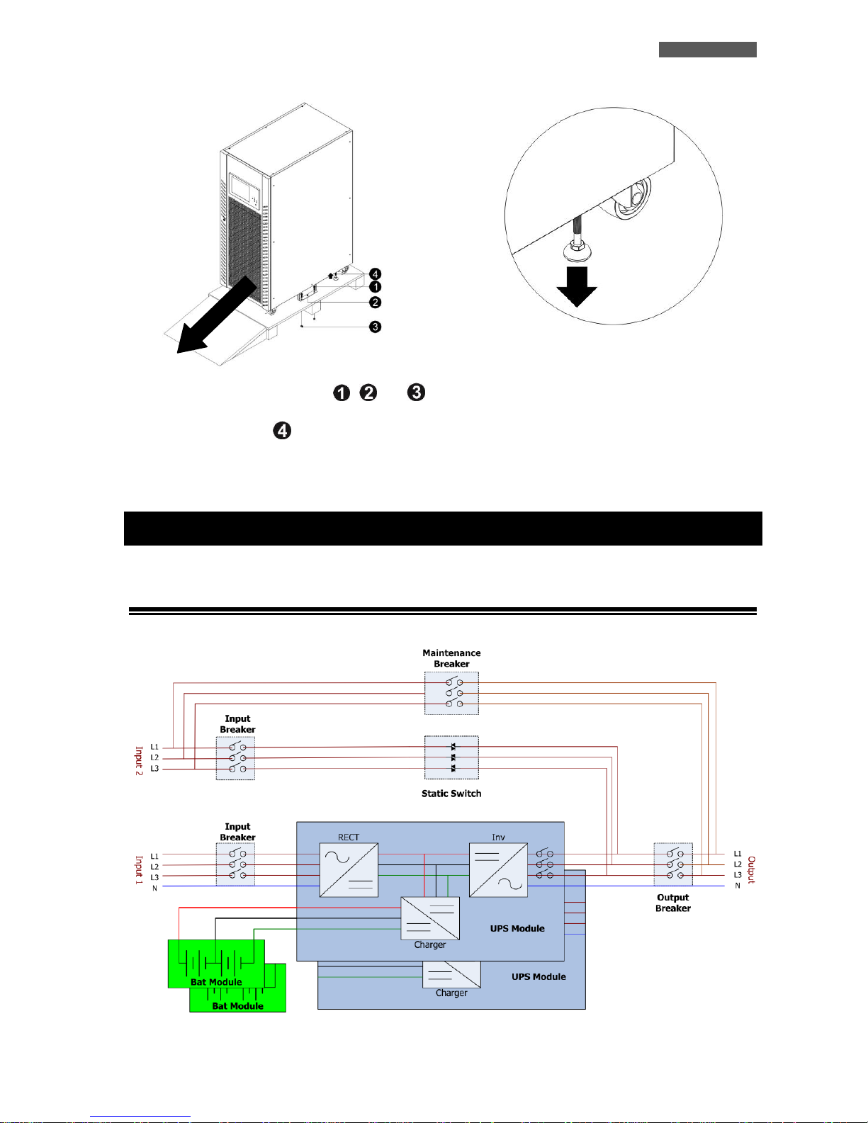
We advise you to follow the steps below explained:
1. Use a forklift to move the product to installed
area. Please make sure the bearing capacity
of forklift is sufficient.
2. Please follow the unpacking order to remove
carton ( and ) and foams ( and ).
ENGLISH
UPS EVO DSP PLUS TT 5 User’s manual
3. Remove two fixing plates ( , and )
located on the two sides of the unit. Loosen
levelling feet ( ) in figure by rotating
them in counter clockwise. Then, move the
cabinet from the pallet.
4. To fix the cabinet in position, simply rotate
levelling feet clockwise.
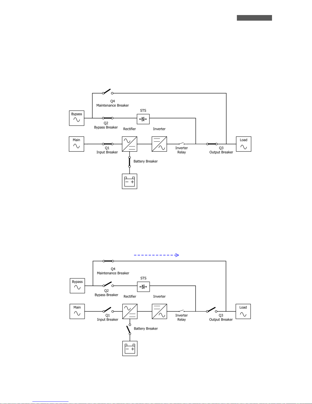
4 Operational Principles
4.1 Block Diagram of UPS
Figure 4.1 – Block and Wiring Diagram
ENGLISH
User’s manual 6 UPS EVO DSP PLUS TT
4.2 Operation Modes
EVO DSP PLUS TT is a Three-Phase, Four-Wire On-Line, Double-Conversion UPS that permits operation in the
following modes:
Standby Mode
Line Mode
Battery Mode
Bypass Mode
ECO Mode
Shutdown Mode
Maintenance Bypass Mode (Manual Bypass)
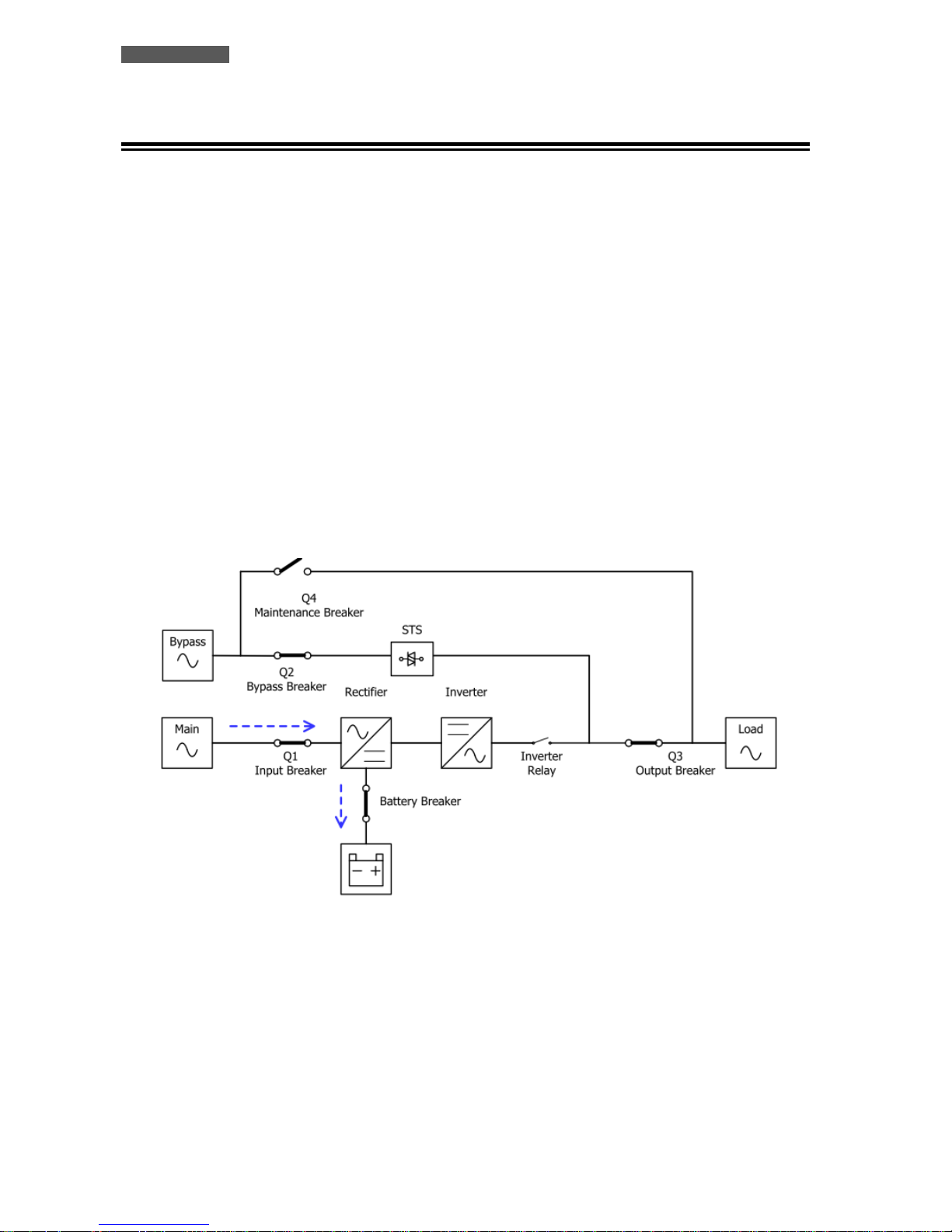
4.2.1 Standby Mode
Upon connecting to Utility Input Power, the UPS is in Standby Mode unless UPS is turned on (if Bypass enable
setting is Disabled), and Charger Function will be active when the Battery is connected. The load is not powered
under this mode.
Figure 4.2 – Standby Mode Diagram
ENGLISH
UPS EVO DSP PLUS TT 7 User’s manual
4.2.2 Line Mode
In Line Mode, the Rectifier delivers power from the mains and supplies DC power to the Inverter and the Charger
charges the Battery. The Inverter filters the DC power and converts it into pure and stable AC power to the load.
Figure 4.3 – Line Mode Diagram
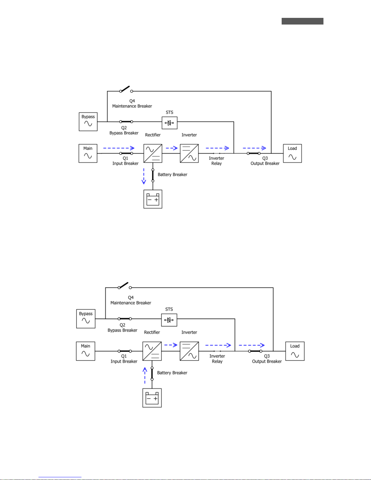
4.2.3 Battery Mode
The UPS automatically transfers to Battery Mode if the Utility fails. There is no interruption to the load upon
failure. In battery mode, the rectifier delivers power from the battery and supplies DC power to the inverter.
The inverter filters the DC power and converts it into pure and stable AC power to the load.
Figure 4.4 – Battery Mode Diagram
ENGLISH
User’s manual 8 UPS EVO DSP PLUS TT
4.2.4 Bypass Mode
Upon connecting to Utility Input Power, the UPS is in Bypass Mode before UPS is turned on (if BYPASS enable
setting is Enabled), and Charger function will be active when Battery is connected.
After UPS has been turned on, if the UPS encounters abnormal situations (over-temperature, overload …, etc.),
the Static Transfer Switch (STS) will perform as a transference of the load from the Inverter to the Bypass source
with no interruption. If the transference is caused by a recoverable reason, the UPS will turn back to Line Mode
when abnormal situation has been solved.
Figure 4.5 – Bypass Mode Diagram
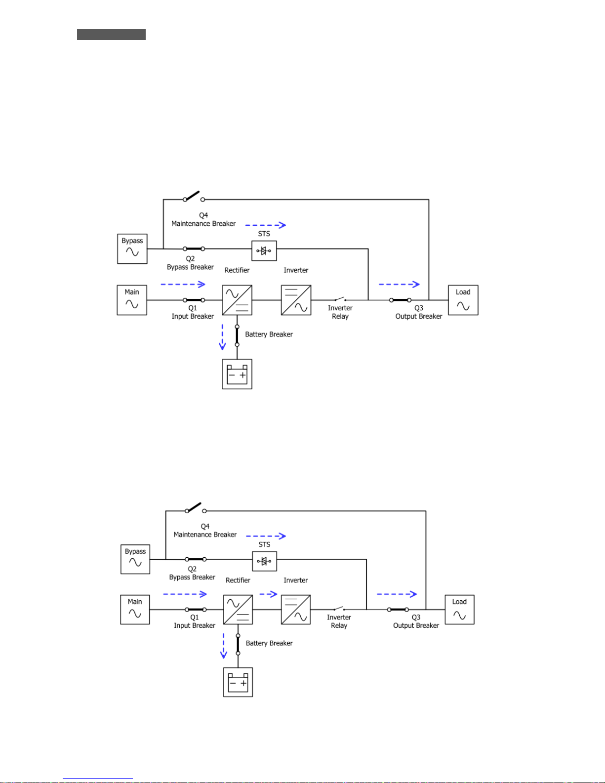
4.2.5 ECO Mode
The ECO Mode can be enabled through the LCD control panel. In ECO mode, the load is diverted to Bypass when
the Bypass voltage and frequency are within the acceptable ranges. If the Bypass is out of range, the UPS will
transfer the power source of load from Bypass to Inverter. In order to shorten the transfer time, the rectifier and
inverter are working when the UPS is in ECO mode.
Figure 4.6 – ECO Mode Diagram
ENGLISH
UPS EVO DSP PLUS TT 9 User’s manual
4.2.6 Shutdown Mode
When you want to switch off the UPS and the power supply is absent, the UPS will enter Shutdown mode. Or
when the UPS has discharged the Battery to the cut-off level, the UPS will also enter into Shutdown Mode.
When the UPS enters this mode, it is going to shut off the control power of UPS. The Rectifier, Charger and
Inverter will be all shutdown.
Figure 4.7 – Shutdown Mode Diagram
4.2.7 Maintenance Bypass Mode
A Manual Bypass Switch is available to ensure continuity of supply to the critical load when the UPS becomes
unavailable e.g. during a maintenance procedure. Before entering the Maintenance Bypass Mode, make sure the
Bypass power source is normal.
Figure 4.8 – Maintenance Bypass Mode Diagram
ENGLISH
User’s manual 10 UPS EVO DSP PLUS TT
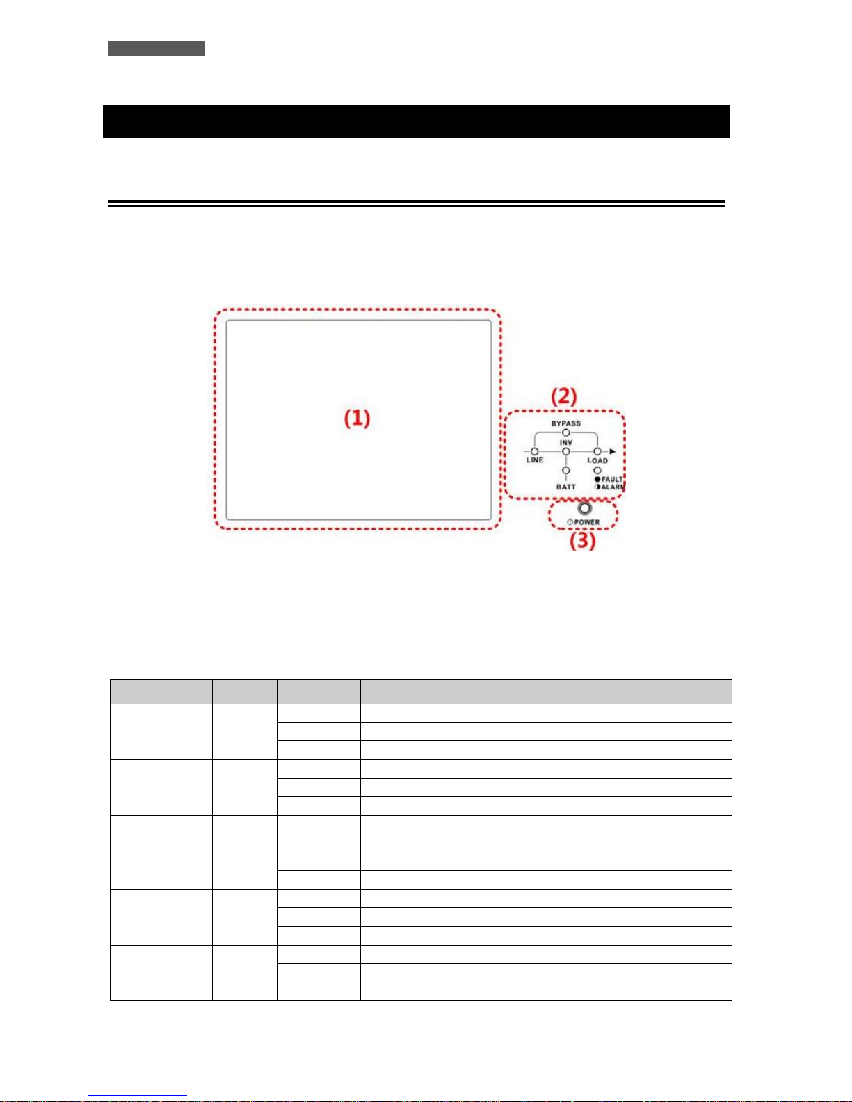
5 Control Panel and LCD Touchscreen
5.1 Introduction
On the front panel of the UPS there is the control interface which is divided into 3 parts: (1) LCD Touchscreen,
(2) LED indications, (3) Power ON/OFF button, as shown in figure 5.1. All the electrical measurements,
parameters, settings, UPS status, battery status and any alarms are displayed on the LCD Touchscreen.
In addition, the UPS emits, during operation, acoustic signals through a buzzer (refer to table 5.3).
Figure 5.1 – Control Panel
(1) LCD Touchscreen
(2) LED indications (refer to table 5-1)
(3) Power ON/OFF Button (refer to table 5-2)
Table 5-1: LED Indications
LED
Color
Status
Definition
LINE
Green
ON
Input source is normal.
Flashing
Input source is abnormal.
OFF
No input source
BYPASS
Yellow
ON
Load on Bypass.
Flashing
Input source is abnormal.
OFF
Bypass not operating.
LOAD
Green
ON
There is power output for the load.
OFF
There is no power output for the load.
INV
Green
ON
Load on inverters.
OFF
Inverters not operating.
BATTERY
Red
ON
Load on Battery.
Flashing
Low battery
OFF
Battery converter is normal and battery is charging.
FAULT/ALARM
Red
ON
UPS fault.
Flashing
UPS alarm.
OFF
Normal.
ENGLISH
UPS EVO DSP PLUS TT 11 User’s manual
Table 5-2: Power Button
Control Key
Description
Power ON/OFF
Turn On UPS or Turn Off UPS (hold 2 seconds).
Table 5-3: Audible Alarm
UPS condition
Description
Power ON/OFF
Buzzer sounds 2 seconds.
Battery mode
Buzzer sounds every 2 seconds.
Low Battery
Buzzer sounds every 0.5 seconds.
UPS alarm
Buzzer sounds every 1 second.
UPS fault
Buzzer continuously sounds.
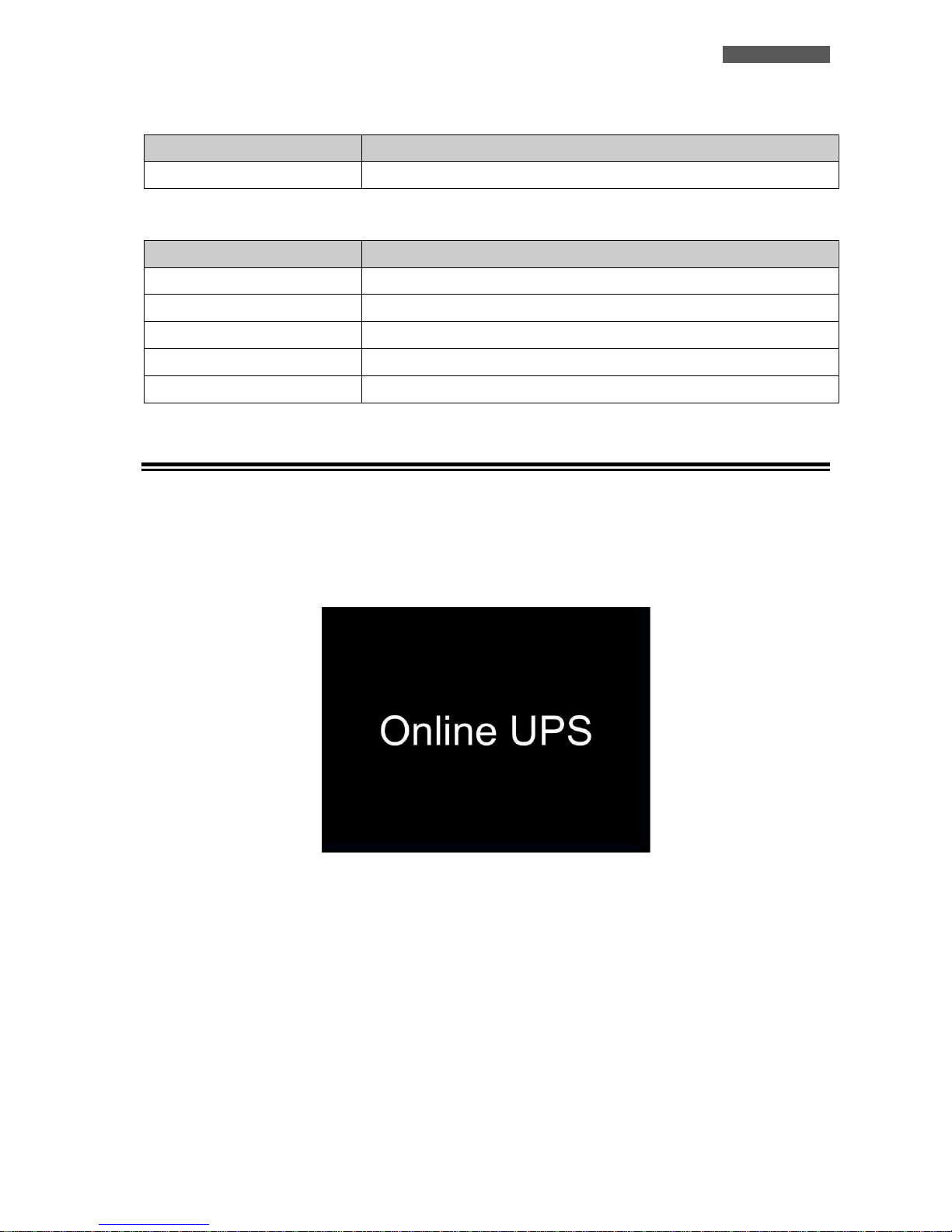
5.2 LCD Touchscreen Description
5.2.1 Initial Screen
Upon powering on, the UPS will execute POST (Power-On Self-Test). The initial screen will remain approximately
5 seconds as shown below.
Figure 5.2 – Initial Screen
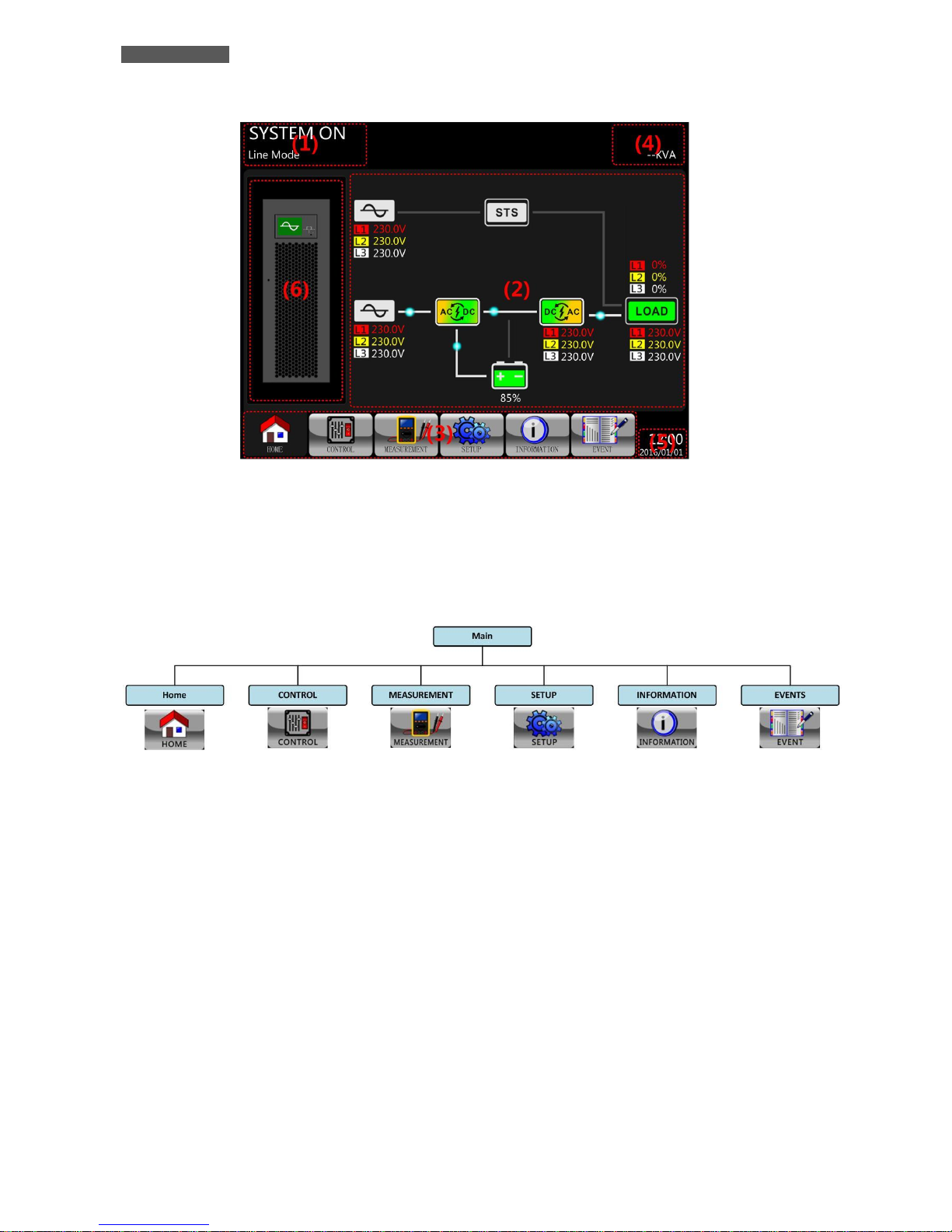
5.2.2 Main Screen (Home)
After initialization, the main screen will display as shown in figure 5.3. Main Screen is divided into six sections.
ENGLISH
User’s manual 12 UPS EVO DSP PLUS TT
Figure 5.3 – Main Screen
(1) Operation Mode: it shows UPS current operation mode and status.
(2) Flow Chart: it shows current flow chart and measurement data.
(3) Main Menu: touch each icon to enter submenu. Refer to figure 5.4 for Menu Tree.
Figure 5.4 - Menu Tree
(4) Power Rating: it show UPS power rating.
(5) Date and Time: it shows current date and time.
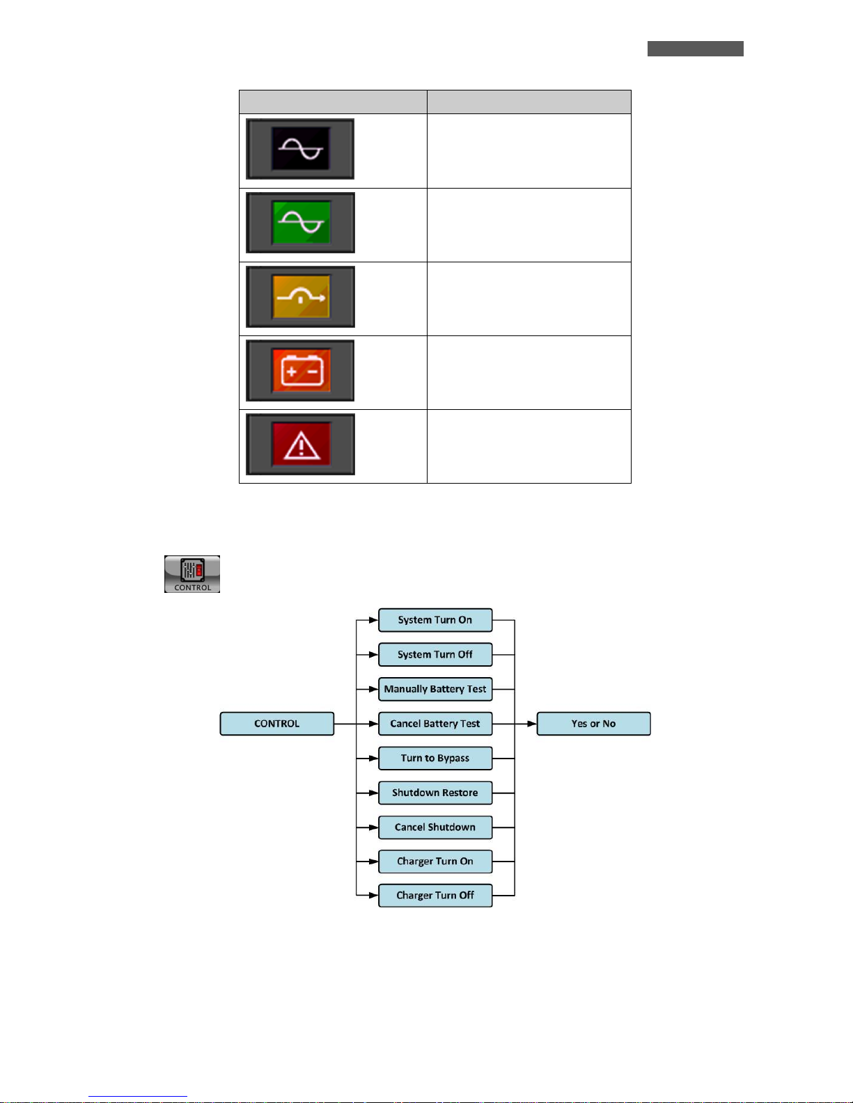
(6) Status: the meanings of each icon are listed as below.
ENGLISH
UPS EVO DSP PLUS TT 13 User’s manual
Icon
UPS status
UPS operates in Standby Mode or
Shutdown Mode.
UPS operates in Line Mode or
Converter Mode.
UPS operates in Bypass Mode or
ECO Mode.
UPS operates in Battery Mode or
Battery Test Mode.
UPS operates in Fault Mode.
5.2.3 Control Submenu
Touch icon to enter into the submenu as shown in figure 5.5 and figure 5.6.
Figure 5.5 - Control Menu Tree
ENGLISH
User’s manual 14 UPS EVO DSP PLUS TT
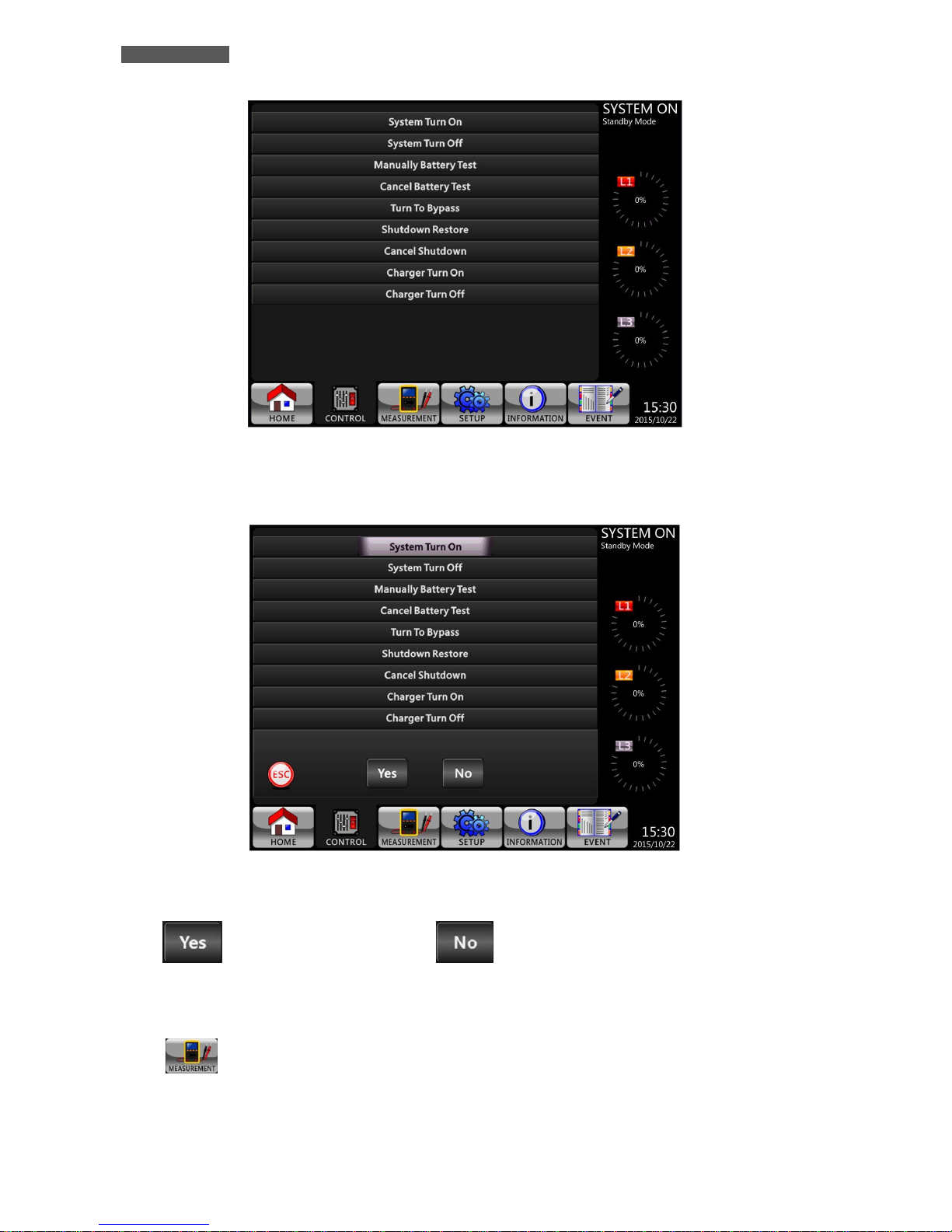
Figure 5.6 - Control Screen Page
Touch any option directly. Then, confirmation screen will pop up, as shown in figure 5.7.
Figure 5.7 - Confirmation Screen
Touch icon to confirm command or touch icon to cancel command.
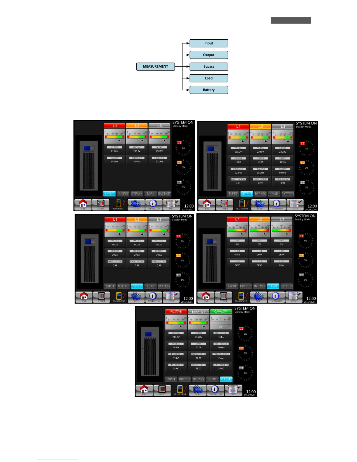
5.2.4 Measurement Screen
Touch icon to enter into the submenu. You may choose Input, Output, Bypass, Load or Battery to
monitor each detailed status. Please refer to figures 5.8 and 5.9 for detailed descriptions. All detailed
measurement items are listed in table 5-4.
ENGLISH
UPS EVO DSP PLUS TT 15 User’s manual
Figure 5.8 - Measurement Menu Tree
Figure 5.9 - System Measurement Screens

ENGLISH
User’s manual 16 UPS EVO DSP PLUS TT
Table 5-4: Measurement Items
Submenu
Item
Explanation
Input
L-N Voltage (V)
Input phase voltage (L1, L2, L3) - step 0.1V
Frequency (Hz)
Input frequency (L1, L2, L3) - step 0.1Hz
Output
L-N Voltage (V)
Output phase voltage (L1, L2, L3) - step 0.1V
L-N Current (A)
Output phase current (L1, L2, L3) - step 0.1A
Frequency (Hz)
Output frequency (L1, L2, L3) - step 0.1Hz
Power Factor
Output power factor (L1, L2, L3)
Bypass
L-N Voltage (V)
Bypass phase voltage (L1, L2, L3) - step 0.1V
Frequency (Hz)
Bypass frequency (L1, L2, L3) - step 0.1Hz
Power Factor
Bypass power factor (L1, L2, L3)
Load
Sout (KVA)
Apparent power - step 0.1KVA
Pout (KW)
Active power - step 0.1KW
Load Level (%)
The percentage of connected load- step 1%
Battery
Positive Voltage (V)
Battery positive voltage - step 0.1V
Negative Voltage (V)
Battery negative voltage - step 0.1V
Positive Current (A)
Battery positive current - step 0.1A
Negative Current (A)
Battery negative current - step 0.1A
Remain Time (Sec)
Battery remaining runtime - step 1sec
Capacity (%)
The percentage of the battery capacity - step 1%
Test Result
Battery test result
Charging Status
Battery charging status
Temperature 01
Temperature of external battery pack - step 0.1℃
Temperature 02
Temperature of external battery pack through extra communication
card T1 - step 0.1℃
Temperature 03
Temperature of external battery pack through extra communication
card T2 - step 0.1℃
Temperature 04
Temperature of external battery pack through extra communication
card T3 - step 0.1℃
Temperature 05
Temperature of external battery pack through extra communication
card T4. - step 0.1℃
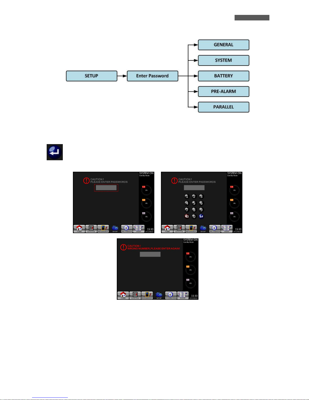
5.2.5 Setup Screen
Touch the to enter into the Setup submenu. It requires a password to access the General, System,
Battery, Pre-Alarm and Parallel submenus as shown in figures 5.10 and 5.11. The default password is “0000”.
ENGLISH
UPS EVO DSP PLUS TT 17 User’s manual
Figure 5.10 - Setup Menu Tree
Touch the grey column and you will be prompt with a number keyboard. Please enter 4-digit password and press
to enter SETUP sub-menu. If incorrect password is entered, you may retry.
Figure 5.11 - Enter Password Screen
There are two levels of password protection: user password and administrator password.
The default password for user is “0000”. It could be changed by users.
The administrator password is owned by trained service personnel.
Different level of password can access to different settings. The setting can be changed in various operation
modes. Please refer to table 5-5 for details (Y = YES: available setting)

ENGLISH
User’s manual 18 UPS EVO DSP PLUS TT
Table 5-5: All setting items in Setup menu
UPS operation
Mode
Setting item
Standby Mode
Bypass Mode
Line Mode
Battery Mode
Battery Test Mode
Fault Mode
Converter Mode
ECO Mode
Authorization
User
Admini-
strator
General
Model Name
Y Y Y Y Y Y Y Y
Y
Language
Y Y Y Y Y Y Y Y Y
Y
Time
Y Y Y Y Y Y Y Y
Y
Change Password
Y Y Y Y Y Y Y Y Y
Y
Baud Rate
Y Y Y Y Y Y Y Y Y
Y
Audible Alarm
Y Y Y Y Y Y Y Y Y
Y
Factory Reset
Y
Y
EEPROM Reset
Y
Y
EPO Function
Y
Y
Save Setting
Y Y Y
Y
Startup Screen
Y Y Y Y Y Y Y Y
Y
System
Output Voltage
Y Y
Y
Bypass Voltage Range
Y Y Y Y Y Y Y Y
Y
Bypass Frequency Range
Y Y
Y
Converter Mode
Y
Y
ECO Mode
Y Y Y Y
Y
Bypass Mode
Y Y
Y
Auto-Restart
Y Y Y Y Y Y Y Y
Y
Cold Start
Y Y Y Y Y Y Y Y
Y
Battery Mode Delay Time
Y Y Y Y Y Y
Y
System Shutdown Time
Y Y Y Y Y Y Y Y
Y
System Restore Time
Y Y Y Y Y Y Y Y
Y
Charger Test
Y Y Y Y Y
Y

ENGLISH
UPS EVO DSP PLUS TT 19 User’s manual
UPS operation
Mode
Setting item
Standby Mode
Bypass Mode
Line Mode
Battery Mode
Battery Test Mode
Fault Mode
Converter Mode
ECO Mode
Authorization
User
Admini-
strator
Battery
Nominal Battery Voltage
Y Y
Y
Battery Capacity in Ah
Y Y Y Y Y Y
Y
Maximum Charging Current
Y Y
Y
Battery Low/Shutdown Setting
Y Y Y Y Y Y
Y
Periodic Battery Test
Y Y Y Y Y Y Y Y
Y
Battery Test Interval
Y Y Y Y Y Y Y Y
Y
Stop by Time
Y Y Y Y Y Y Y
Y
Stop by Battery Voltage
Y Y Y Y Y Y Y
Y
Stop by Battery Capacity
Y Y Y Y Y Y Y
Y
Battery Age Alert
Y Y Y Y Y Y Y Y
Y
Temperature Compensation
Y Y Y Y Y Y Y Y
Y
Charging Voltage
Y Y
Y
Auto-Restart Battery Voltage
Y Y Y Y Y Y Y Y
Y
Pre-Alarm
Line Voltage Range
Y Y Y Y Y Y Y Y
Y
Line Frequency Range
Y Y Y Y Y Y Y Y
Y
Load
Y Y Y Y Y Y Y Y
Y
Parallel
UPS Parallel
Y Y
Y
Independent Battery
Y Y
Y
Setting Procedure
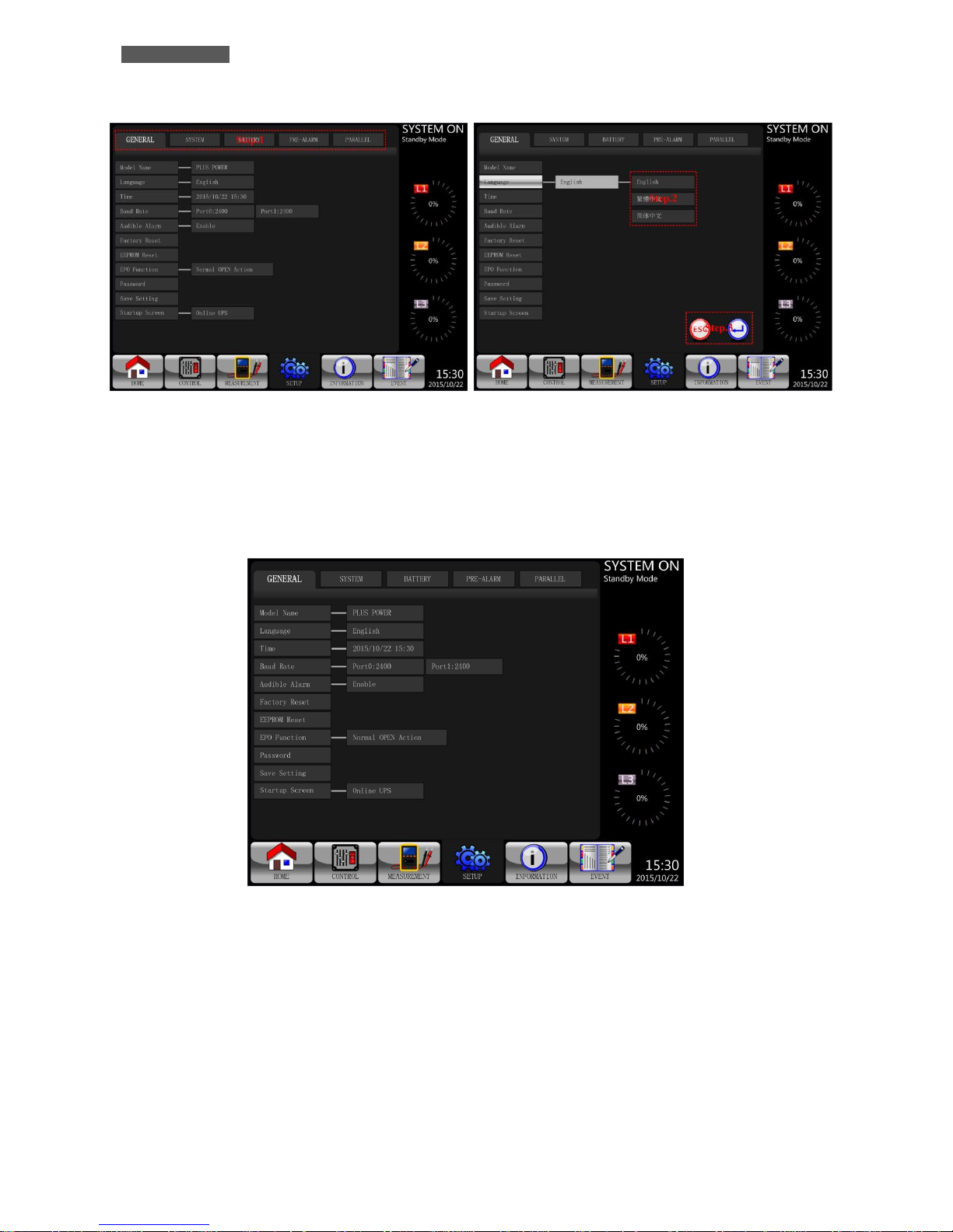
1. Choose between General, System, Battery, Pre-Alarm and Parallel.
2. Each item will show current value. Simply click current value and it will list all alternatives in the end.
3. Choose to confirm the change or choose icon to cancel any modifications.
ENGLISH
User’s manual 20 UPS EVO DSP PLUS TT
Figure 5.12 - Setting Procedure
5.2.5.1 Setup General Screen
The Setup-General screen and setting options are shown in figure 5.13 and table 5-6.
Figure 5.13 - Setup-General Screen

ENGLISH
UPS EVO DSP PLUS TT 21 User’s manual
Table 5-6: Setup General Setting List
Setting Item
Sub Item
Explanation
Model Name
--
Set UPS Name (xxxxxxxxxx).
The max. length is 10 characters.
Time
Adjust Time
Set current date and time.
Format: (yyyy / mm / dd hour : min : sec)
MUST be set after UPS installation
System Installed Date
Set system installed date.
Format: (yyyy / mm / dd)
2015/1/1 (Default)
MUST be set after UPS installation
System Last Maintain
Date
Set system latest maintenance date.
Format: (yyyy / mm / dd)
MUST be set after UPS installation
Battery Installed Date
Set battery installed date.
Format: (yyyy / mm / dd)
MUST be set after UPS installation
Battery Last Maintain
Date
Set battery latest maintenance date.
Format: (yyyy / mm / dd)
MUST be set after UPS installation
Baud Rate
--
Set COM Baud Rate:
2400 (Default)
4800
9600
Audible Alarm
--
Set Audible Alarm:
Disable
Enable (Default)
Factory Reset
--
Restore to factory default setting: refer to table 5-7.
EEPROM Reset
--
Restore EEPROM to default setting: refer to table 5-7.
EPO Function
--
Set EPO active status:
Normal Close Active
Normal Open Active (Default)
Password
--
Set New Password. 0000 (Default)
Save Settings
--
Save all settings to EEPROM.
Use this feature to save the setting(s) you have done.
Startup Screen
--
Set up initial screen (xxxxxxxxxxxx).
The max. length is 12 characters.

ENGLISH
User’s manual 22 UPS EVO DSP PLUS TT
Table 5-7: EEPROM Reset Category List
Setting Item
Factory Reset
EEPROM Reset
General
Model Name
Language Y Y
Adjust Time
System Installed Date
Y
System Last Maintain Date
Y
Battery Installed Date
Y
Battery Last Maintain Date
Y
Change Password
Y
Baud Rate Y
Audible Alarm
Y
Y
Factory Reset
EEPROM Reset
EPO Function Y
Save Setting
Startup Screen
System
Output Voltage
Y
Bypass Voltage Range
Y
Y
Bypass Frequency Range
Y
Y
Converter Mode
Y
Y
ECO Mode Y Y
Bypass Mode Y Y
Auto-Restart Y Y
Cold Start Y
Battery Mode Delay Time
Y
Y
System Shutdown Time
Y
Y
System Restore Time
Y
Y
Charger Test
Battery
Nominal Battery Voltage
Y
Y
Battery Capacity in Ah
Y
Y
Maximum Charging Current
Y
Y
Battery Low/Shutdown Setting
Y
Y
Periodic Battery Test
Y
Y
Battery Test Interval
Y
Y
Stop by Time Y Y
Stop by Battery Voltage
Y
Y
Stop by Battery Capacity
Y
Y
Battery Age Alert
Y
Y
Temperature Compensation
Y
Y
Charging Voltage
Y
Y
Auto-Restart Battery Voltage
Y
Y
Pre-Alarm
Line Voltage Range
Y
Line Frequency Range
Y
Load Y
ENGLISH
UPS EVO DSP PLUS TT 23 User’s manual
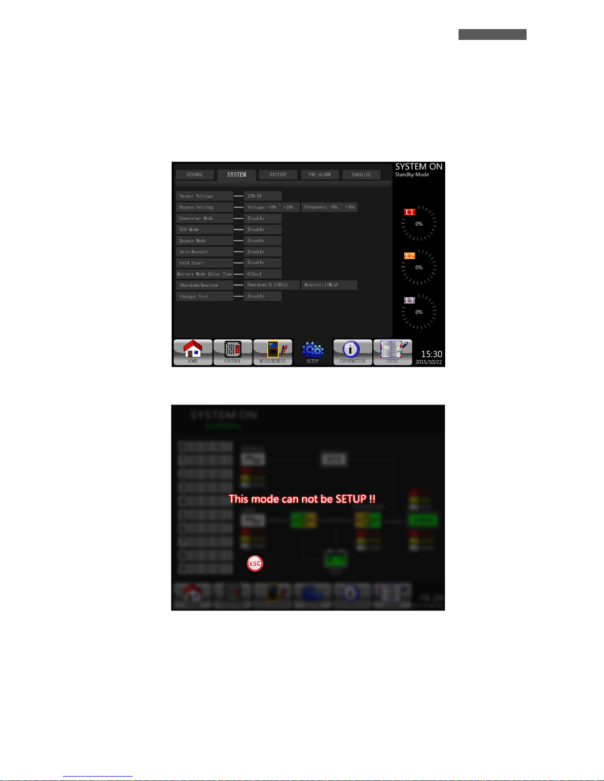
5.2.5.2 Setup System Screen
The Setup-System Screen and setting options are shown in figure 5.14; refer to table 5-8. System Setting can only
be access when UPS is operated in certain mode. Please refer to table 3-5 for the details. If an option is not
available under specific mode, a warning screen will appear such as in figure 5.15
Figure 5.14 - Setup-System Screen
Figure 5.15 - Warning Screen

ENGLISH
User’s manual 24 UPS EVO DSP PLUS TT
Table 5-8: Setup-System Setting List
Setting Item
Sub Item
Explanation
Output
Voltage
--
Set Output Voltage:
220Vac (Default)
230Vac
240Vac
Bypass Setting
Bypass Voltage
Range
Set Bypass Voltage Range.
Upper limit:
+10%
+15% (Default)
+20%
Lower limit:
-10%
-20% (Default)
-30%
Bypass
Frequency
Range
Set bypass Frequency range.
Upper/ Lower limit:
+/- 1Hz
+/- 2Hz
+/- 4Hz (Default)
Converter
Mode
--
Set Converter Mode:
Disable (Default)
Enable
ECO Mode
--
Set ECO Mode:
Disable (Default)
Enable
Bypass Mode
--
Set Bypass Mode:
Disable (Default)
Enable
If you need the Bypass power when UPS is OFF, please enable it.
Auto-Restart
--
Set Auto-Restart:
Disable
Enable (Default)
After “Enable” is set, once UPS shutdown occurs due to low battery and
then utility restores, the UPS will return to Line Mode.
Cold Start
--
Set Cold Start:
Disable
Enable (Default)
After “Enable” is set, the UPS can be turned on without connecting to
utility by pressing BATTERY START Button. Refer to section 7.2 “Cold
Start Startup” for the details.
Battery Mode
Delay Time
--
Set System Shutdown Delay Time in Battery Mode (0~9990 sec):
0: Disable (Default)
NOT 0: Enable
When this feature is enabled, UPS will shut off output after UPS operates
in Battery Mode for certain seconds.
Shutdown/
Restore
System
Shutdown Time
Set System Shutdown Time (0.2~99 min):
0.2 min (Default)
This delay time will start counting when the CONTROL-Shutdown
command is executed.
System Restore
Time
Set System Restore Time (0~9999 min)
1 min (Default)
This delay time will start counting after shutdown time is elapsed when
the CONTROL-Shutdown Restore command is executed.
Charger Test
--
Set Charger Test:
Disable (Default)
Enable
 Loading...