

Page 1
Technovision Interactive
421VS
Operating Guide
Revision 2017-11
TECHNOVISION INTERACTIVE INC
www.technovision.com
Page 2 Technovision 421VS Operating Guide
Page 2

Technovision 421VS Operating Guide Page 3
Table of Contents
421VS SYSTEM OVERVIEW.....................................................................4
TTL CONTROL (2 AND 4 LINE MODE).................................................. 4
2-LINE TTL CONTROL..............................................................................5
4-LINE CONTROL (DRY CONTACT CLOSURE).................................. 5
RS232 CONTROL (9600,8,N,1)....................................................................6
DETERMINING THE SWITCHER ADDRESS:......................................................6
TECHNICAL SPECIFICATIONS..............................................................7
FUNCTION SWITCH SETTINGS ON MAIN BOARD (DS1).................7
421VS POWER REQUIREMENTS: .......................................................... 7
CSYNC OUTPUT:......................................................................................7
CONTROL PORT CONFIGURATION (DB9 MALE): ............................... 7
AVAILABLE OPTIONS...............................................................................7
Page 4 Technovision 421VS Operating Guide
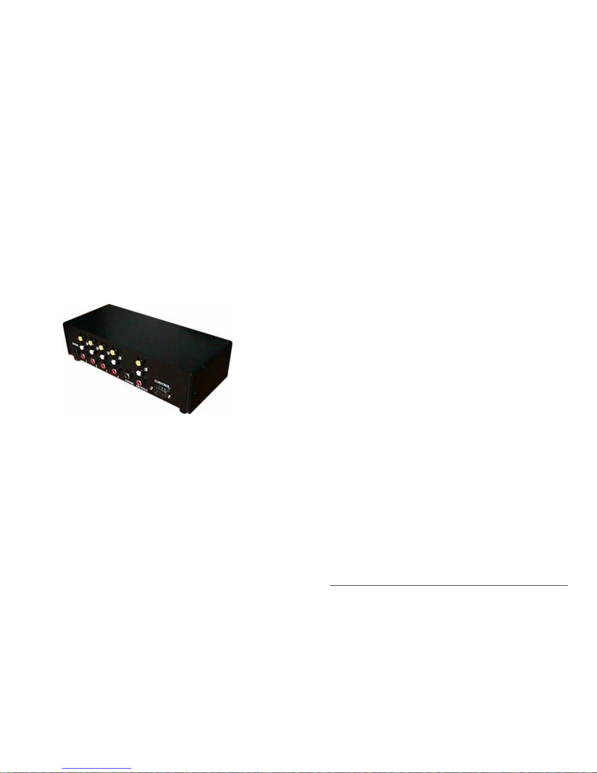
421VS SYSTEM OVERVIEW
The Technovision PC-2 is a 4 to 1 vertical interval (audio follow video)
switcher capable of being controlled various ways, using the external
CONTROL connector on the back:
The different modes of control are:
• 2-line TTL control (DEFAULT)
• 4-line TTL (dry contact closure) control
• RS232 control
CAUTION
Please make sure the power supply to the 421VS is unplugged before
attaching cables. Static discharge into the 421VS through any of its
connectors may damage the switcher.
**NOTE**
VIDEO INPUT#1 MUST BE CONNECTED – THIS INPUT IS USED
TO GENERATE THE VERTICAL SYNCH PULSE.
TTL CONTROL MODES: (2 and 4 line mode)
• The default setting for the switcher is 2-line TTL controls (DIP switch
positions 1 and 2 OFF).
• INPUT CONTROL lines are pulled high internally by the switcher. To
select an input you will have to pull the appropriate input control lines on
the CONTROL connector to ground. The default video input at power-up
is 1 (all INPUT CONTROL lines high).
• In 2-line mode, the control lines must be kept low or the input will switch
back to 1.
• In 4-line mode the control line can be pulled low momentarily.
• Pin 1 is input control line 1. (Used in 2 and 4-line mode).
• Pin 6 is input control line 2. (Used in 2 and 4-line mode).
• Pin 2 is input control line 3. (Used in 4-line mode only).
• Pin 7 is input control line 4. (Used in 4-line mode only).
• Pin 5 is the ground.
Page 3

Technovision 421VS Operating Guide Page 5
CONTROL MODE: 2-line TTL Control
DIP-switch position 1 and 2 must be OFF. Control lines MUST be kept low
to select the video input.
INPUT # PIN 1 on CONTROL PIN 6 on CONTROL
1 HIGH (OPEN) HIGH (OPEN)
2
Pulled LOW to Ground
HIGH (OPEN)
3 HIGH (OPEN)
Pulled LOW to Ground
4
Pulled LOW to Ground Pulled LOW to Ground
Example: To select INPUT #2 you must contact pin 1 to ground (pin 5).
Releasing it would return the INPUT to #1.
CONTROL MODE: 4-line TTL Control (dry contact closure)
DIP-Switch position 1 must be OFF and position 2 must be ON. Input
control lines can be pulled low (dry contact closure with pin 5) momentarily
to select the input.
INPUT # PIN 1 PIN 6 PIN 2 PIN 7
1
PULLED
LOW
HIGH
(OPEN)
HIGH
(OPEN)
HIGH
(OPEN)
2 HIGH
(OPEN)
PULLED
LOW
HIGH
(OPEN)
HIGH
(OPEN)
3 HIGH
(OPEN)
HIGH
(OPEN)
PULLED
LOW
HIGH
(OPEN)
4 HIGH
(OPEN)
HIGH
(OPEN)
HIGH
(OPEN)
PULLED
LOW
Example: To select INPUT2 you can momentarily contact pin 6 to ground
(pin 5).
Page 6 Technovision 421VS Operating Guide
CONTROL MODE: RS232 Control (9600, 8, N, 1)
• You will have to remove the lid on the 421VS and move Function switch
position 1 to the ON position for RS232 control.
• The protocol is 9600 baud, no parity, 8 bits, 1 stop.
• The switcher receives data on pin 3 and transmits on pin 8 of the DB9
male connector on the back of the switcher. Data ground is pin 5.
• On start-up the switcher will transmit "Technovision 421VS".
• A single byte is sent to the switcher to select the input signal. This byte is
echoed back by the switcher upon receipt of the command.
The protocol of the single byte command to the switcher is as follows:
• Bits 7 to 4 are always ∅∅11 (30H)
• Bits 3 and 2 are the switcher address (0 to 3). Default is ∅∅
• Bits 1 and 0 are the input select value (I). Value of ∅=input 1, 1=input 2,
2=input 3 and the value of 3=input 4.
Example for a switcher with the address of ∅∅ (DEFAULT):
Input # RS232 character to transmit to the switcher (address 0)
1
30H (30H+address∅∅ + ∅), ASCII "∅" , decimal 48
2
32H (30H+address∅∅ + 1), ASCII "1" , decimal 49
3
32H (30H+address∅∅ + 2), ASCII "2" , decimal 50
4
33H (30H+address∅∅ + 2), ASCII "3" , decimal 51
Determining the switcher address:
Address Value to add
0 0
1 4
2 8
3 12
Example: To select INPUT#3 on the 421VS with the address of 0 (default),
you would transmit (30H+0+3) - the character “3” to the 421VS.
Example: To select INPUT#3 on the 421VS with the address of 1, you would
transmit (30H+4+3) - the character “7” to the 421VS.
Page 4

Technovision 421VS Operating Guide Page 7
TECHNICAL SPECIFICATIONS
FUNCTION SWITCH SETTINGS ON MAIN BOARD (DS1)
SWITCH
POSITION #
Function
ON
OFF
(Default)
1 Control Mode RS232
TTL
2 4 / 2 line select 4-line
2-line TTL
3 Value of bit 1 of
switcher address
Switcher Address
bit 1 = 1
Address
bit 1 = 0
4 Value of bit 0 of
switcher address
Switcher Address
bit 0 = 1
Address
bit 0 = 0
421VS POWER REQUIREMENTS:
16 VDC, 200ma, 2.1 mm connector, and center positive.
CSYNC OUTPUT:
An RCA connector provides the composite sync signal. This signal along with
the vertical switch timing is derived from the video signal on INPUT 1.
CONTROL PORT CONFIGURATION (DB9 male):
Pin# Description Pin# Description
1 Input control line 1 6 Input control line 2
2 Input control line 3 7 Input control line 4
3 RS232 Receive data RX
(INPUT)
8 RS232 Transmit data TX
(OUTPUT)
4 Secondary RX 9 Secondary TX
5 GROUND
AVAILABLE OPTIONS
Part # Description
421RACK 19" EIA RACK MOUNT KIT
Page 8 Technovision 421VS Operating Guide
 Loading...