

Page 1
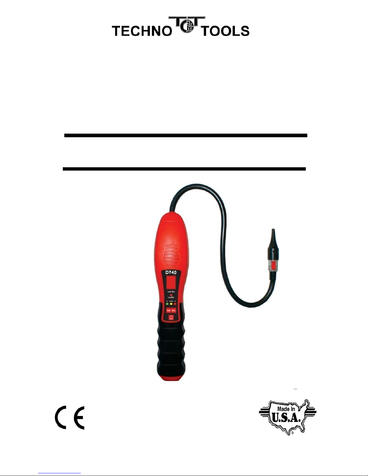
Model D740
H2 Tracer Gas Leak Detector
User Manual
Detects H2/N2 5/95% Tracer Gas
Design certified by
ACSI to meet
SAE Standard J2970
Page 2

INTRODUCTION
The D740 features a long life sensor technology that is designed to
detect H2/N2 5/95% Tracer Gas mixture, also known as “Forming
Gas”.
The instrument’s unique digital leak size indicator takes the
guesswork out of whether or not to repair a small leak. The digital
display is independent from the audio alarm and sensitivity level,
allowing the precise pinpointing of the leak source.
When used with the H2/N2 5/95%Tracer Gas mixture, the D740 will
detect leak rates equivalent to 4 g/year of R-134a in the “HI” setting
and 7 g/yr in the “NORM” setting while moving the probe at
3”/second. This complies with SAE Standard J2970 sections 7.2 and
7.3. Leak Testing with Tracer Gas is consistent with the teachings
from EUStandards EN35422, EN14624, Article 6, Paragraph 3 of EU
Directive 2006/40/EC and the EU F-gas rules.
FEATURES
Unique numeric leak size
Indicator
Long life, stable sensor
H2 sensitivity-4 grams/year
R-134a equivalent
Automatic calibration and
reset to ambient
Visual LED leak alarm near
the sensor
3 adjustable sensitivity levels
Low battery indicator
True mechanical pump
Audio mute function
Uses 4 AA alkaline batteries
CE Certified
Comfortable Santoprene grip
2- year warranty
Made in USA
1
Page 3
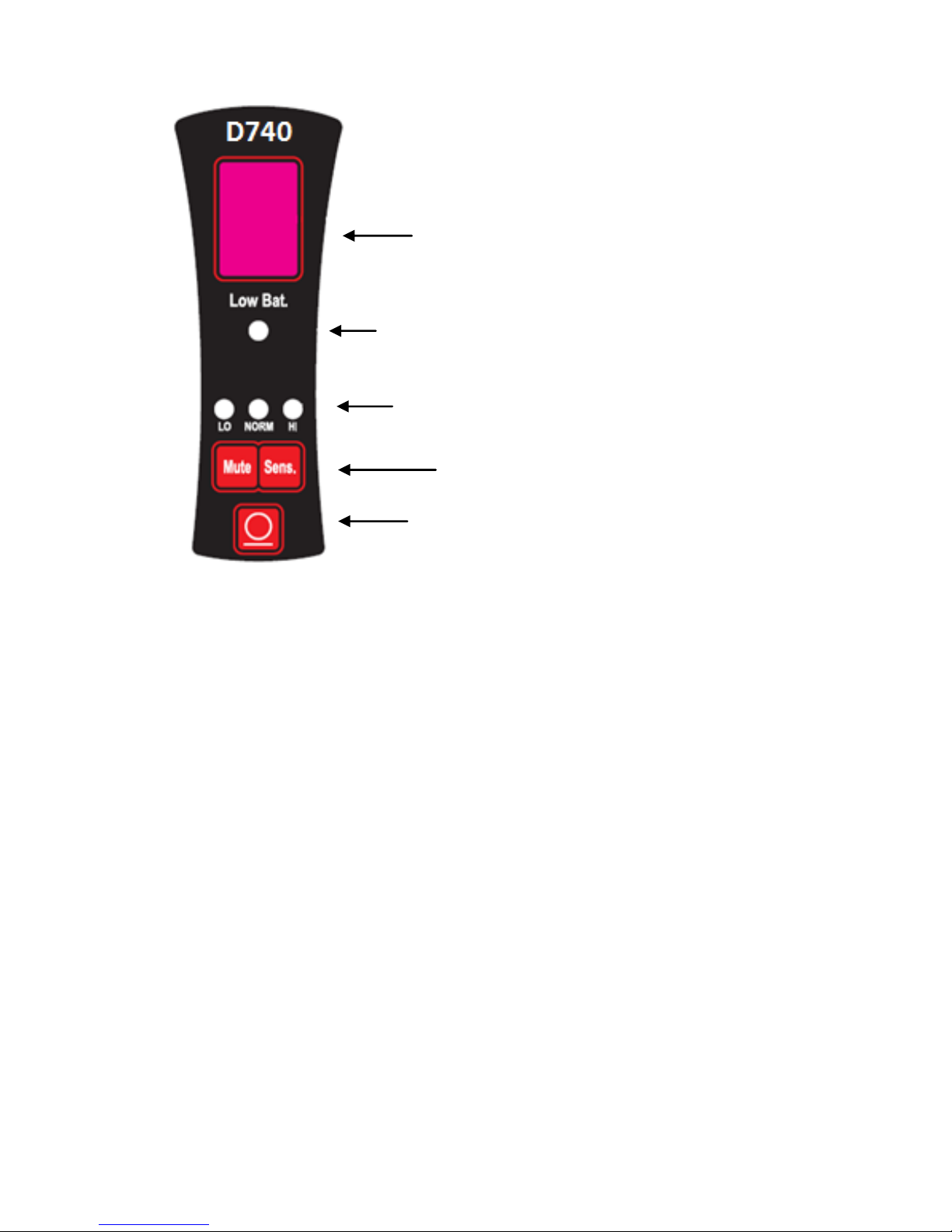
D740 Control Panel
Operating Instructions
1. TURN ON: Press the ON/OFF button once to turn on and again to turn off.
NOTE: Hold button down for approximately 1 second to turn unit off.
2. WARM UP: The detector automatically starts heating the sensor. During the
heating cycle, the digital leak size indicator will flash 0 and the detector will
sound a slow “beep”. Warm up is usually less than 20 seconds.
3. READY: The detector is ready to begin searching for leaks when the flashing 0
stops and the green sensitivity LED turns on (7g/yr setting). The audio “beep”
increases in frequency and the probe LED begins to blink steadily.
4. SEARCHING: When searching for leaks, move the sensor tip along a/c lines
and fittings no further away than 3/8” and moving at approximately 3”/second. If
the detector alarms, make smaller sweeps back and forth until the leak source
can be pin pointed. Note: The D740 only responds to changes in leak
concentration. The alarm will re-set automatically if the sensor tip is held
at the leak source. If the leak detector has been out of use for an
extended period, weeks or months, the following action is recommended.
Power on the instrument and allow it to come out of warm up. Then run it
with the sensitivity level in the Hi (high) position for several minutes
before testing it with the Leak Test Vial. This action will guarantee that
the sensor is fully conditioned for maximum response to refrigerant gas.
Digital Leak Size
Indicator
Low Battery
Indicator
Sensitivity Level Indicators
Audio Mute &
Sensitivity Level Selectors
Power
On/Off
2
Page 4

Tracer Gas Detection
Tracer Gas consists of a non-toxic, non-flammable,
environmentally friendly (non-polluting) mixture of 5% Hydrogen
and 95% Nitrogen. For this reason, the Tracer Gas can be released
into the environment after the leak detection procedure is
completed.The D740 detects the hydrogen component of the
Tracer gas and because hydrogen molecules are so small, it is an
ideal gas for leak detection.
The Tracer Gas is charged into an empty system at a pressure of
approximately 75 psi (5bar). Run the engine with air conditioner on
briefly to properly distribute the H2N2 Tracer Gas. As hydrogen is
lighter than air, always probe slightly above the suspected leak
area. Begin with the detector set in the “HI” (4g/yr setting). Move
the probe at a rate of approximately 3”/second and as close as
possible to the suspected area. If looking for an apparently larger
leak, check first at the 7 g/yr “Norm” setting or the “LO” setting.
Once the source of the leak is located and repaired, the Tracer Gas
can be released and the system can be recharged again with
refrigerant. A final check should be performed using an SAE
certified refrigerant gas leak detector such as the D440A or the
D440A-UV.
Leak Size Indicator
The digital leak size indicator remains off normally but once a leak
is detected, a number from 1-9 will be displayed for the H2/N2
Tracer Gas regardless of the sensitivity setting.
The number will continue to increase or decrease depending on
the amount of Tracer Gasis sensed. The maximum value will be
displayed once the leak source has been located. The table below
can be used to approximate the size of leak
:
Maximum # displayed
Approx. Leak Size (oz/yr)
1 -3
0.15
4-6
0.15 to 0.5
7-9
>0.5
3
Page 5
Adjusting Sensitivity Levels
The Leak Detector will default to the “NORM” sensitivity level
automatically once the unit comes out of the warm up cycle and
the green LED will turn on.
To change sensitivity levels, press the SENS once for “HI”
sensitivity (red LED will turn on) and again for “LO” sensitivity
(yellow LED will turn on).
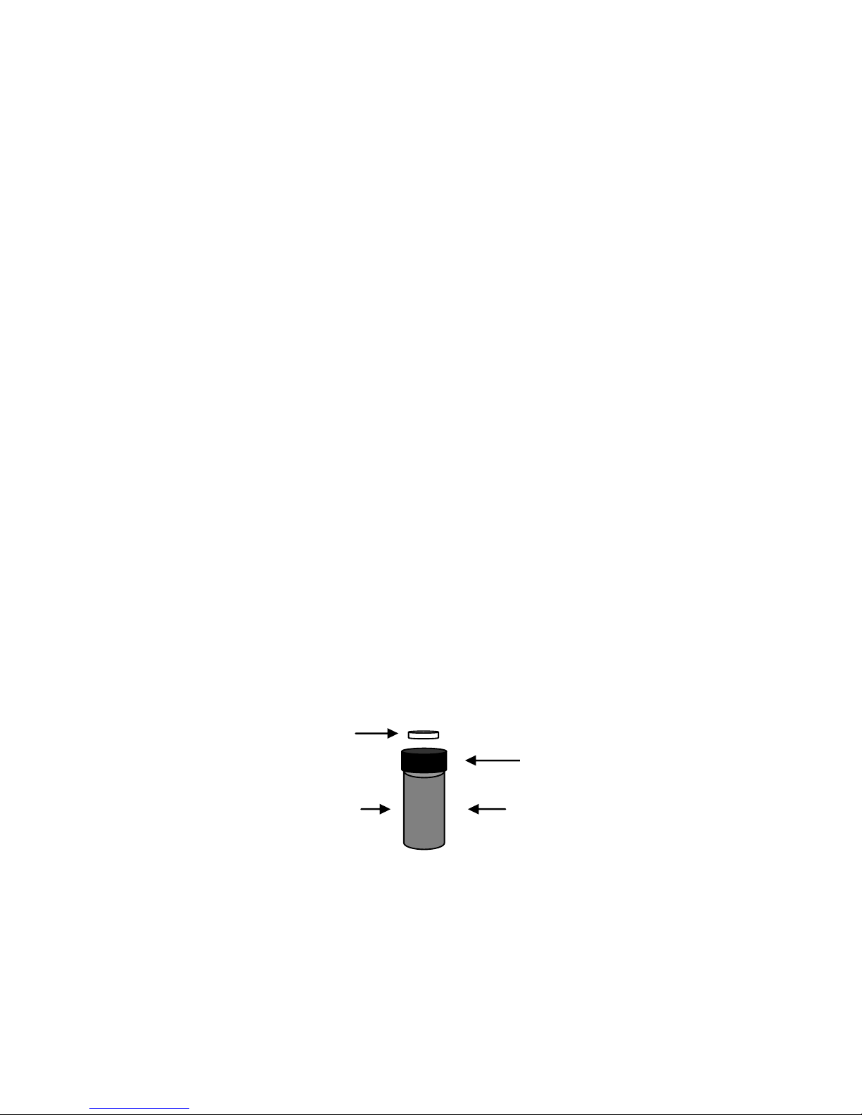
Leak Test Vial
The leak detector comes with a Leak Test Vial that allows the
user to make sure the detector is performing properly.
To test the instrument
1. Remove the colored label dot in the center of the screw
cap to expose the vent hole in the top of the screw cap.
(see fig. below)
2. Turn on the detector and allow the unit to complete the
warm up cycle.
3. Place the sensor close to the small hole in the top of the
Leak Test Vial. The beep rate should increase and the
Digital Leak Size Indicator should display a number from
3-6 indicating that the sensor and electronics are working
properly.
NOTE: Replace the Test Vial back in the nylon bag when
not in use to extend the shelf life. Replace Test Vial when
the green color is less than ¼ full or at the time of the
expiration date.
4
Leak Test Vial
Remove label dot over
vent hole before testing
Expiration Date
on label
Vial Cap with vent
hole
Page 6
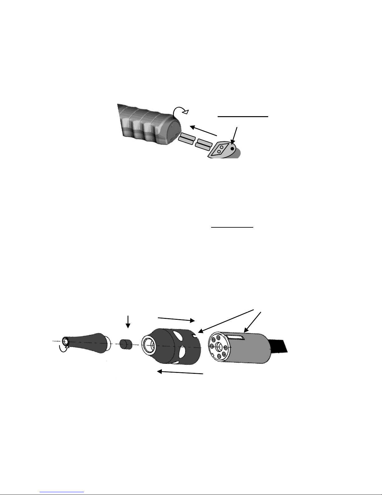
Maintenance
Polarity Mark
Filter
Keyway alignment
Pull straight out (do not
Unscrew tip to
replace filter
Push straight on (do not
twist) to install sensor
Batteries:
Install Batteries: Remove screw located at rear end of unit and
pull down hinged battery door to open as shown. Always insert
all four batteries into the battery compartment in the same
direction. Note polarity mark on the inside of the battery door
for proper battery orientation.
Sensor:
Replace Filter: Unscrew sensor tip as shown to replace filter.
Replace filter whenever it becomes visibly dirty or every 2 to 3
months depending on use.
Replace Sensor: Remove sensor by pulling out of socket. Install
the new sensor by aligning the notch in sensor cover with the raised
keyway on sensor socket holder (see figure below).
Note: Do not force sensor into socket. Misalignment can
damage the sensor pins.
5
IMPORTANT: Make sure sensor is fully inserted for proper
operation. The detector will stay in warm-up mode and the on/off
switch will become inoperative if the sensor becomes loose or is
not fully inserted.
Page 7

Low Battery Indicator
Replace the 4 AA Alkaline batteries when the red LED on the
control panel is lit. Follow battery installation instructions under
Maintenance section.
Audio Mute Function
To silence or mute the audio beep and alarm signal, press the
MUTE button. To restore the audio sound, press the MUTE
button again. (Note: a few seconds is required to restore sound
if the mute button is pressed in rapid succession.)
Cross Sensitivity to Automotive Chemicals
Some automotive solvents and chemicals have similar hydrocarbon
properties as H2 and may elicit a positive response (<20 seconds)
from the D740. Before leak checking, clean up any chemicals in the list
below that elicit a positive response.
Product Specifications
Model #
D740
Name
Leak Detector, H2 Tracer Gas
Sensitivity
4 g/yr R-134a equivalent
Sensor Life
>300 hours
Response Time
Instantaneous
Power Supply
4 AA Alkaline batteries
Battery Life
4-6 hours continuous
Warm up time
< 20 seconds
Probe length
17 inches
Numerical Display
7 segment digital display (1 to 9)
Weight, lbs
1.5 lbs
Warranty
2 years
Chemical Name/Brand
Response
Methanol based windshield wash fluid
N
Ford Spot Remover (Wet)
Y
Ford Rust Inhibitor
Y
Ford Gasket Adhesive (Wet)
Y
Loctite Natural Blue degreaser (diluted)
Y
Ford Brake Parts Cleaner
Y
Ford Silicone Rubber (uncured)
Y
Motorcraft Antifreeze heated to 160 deg F
N
Gunk liquid wrench
Y
Ford silicone lubricant
N
Ford Pumice lotion (with solvent)
Y
Ford Motorcraft brake fluid
Y
Ford Carburetor Cleaner
Y
Transmission fluid heated to 160 deg F
N
Mineral engine oil heated to 160 deg F
N
6
Page 8

Replacement Parts
Item
Part Number
H2/N2 Sensor with Filter
AC-SEN00012A
Sensor filters (5 pack)
AC-FIL0001A
Leak Test Vial
AC-LSA0001A
Parts Kit(includes H2 sensor, test vial, & filter kit)
AC-KIT0005A
Carrying Case
AC-CAS0001A
RETURN FOR REPAIR POLICY
Every effort has been made to provide reliable, superior quality
products. However, in the event your instrument requires repair,
forward unit to Service Center freight prepaid to the address below
with return address, phone number and/or email address.
SERVICE CENTER
2651 W 81st Street
Hialeah, FL33016
WARRANTY POLICY
The D740H2/N2 Tracer Gas Leak Detector is warranted to be free
of defects in materials and workmanship for a period of two years
from the date of purchase. This warranty applies to all repairable
instruments that have not been tampered with or damaged through
improper use including unauthorized opening of the unit. Please
ship warranty units that require repair freight prepaid to Service
Center along with proof of purchase, return address, phone
number and/ or email address.
Call Toll Free: 800-222-0956
Fax: 786-235-1202
 Loading...