

Technotherm W SE 15 Slim, WSE 50 Slim, WSE 80 Slim, WSE 30 Slim, WSE 100 Slim Operating And Installation Instructions
Page 1
WW SE 1
WW SE 1
WSE 15 Slim
WSE 30 Slim / WSE 50 Slim
WSE 80 Slim / WSE 100 Slim
SE 1
SE 1
5 Slim5 Slim
5 Slim5 Slim
WW SE 30 Slim / W
WW SE 30 Slim / W
SE 30 Slim / W
SE 30 Slim / W
SE 50 SlimSE 50 Slim
SE 50 SlimSE 50 Slim
WW SE 80 Slim / W
WW SE 80 Slim / W
SE 80 Slim / W
SE 80 Slim / W
SE 1SE 1
SE 1SE 1
00 Slim00 Slim
00 Slim00 Slim
GB
9
10
D
2
3
Montage- und Gebrauchsanleitung
Wandspeicher
Operating and installation instructions
Wall-mounted storage water heater
Page 2
Wandmontage
Sehr geehrter Kunde!
Wir wünschen Ihnen viel Freude mit dem neuen Heißwasserspeicher. Das Gerät ermöglicht
Ihnen einen hohen Bedienkomfort und einen energiesparenden Betrieb. Vor der Inbetriebnahme informieren Sie sich bitte über die richtige Montage, Inbetriebnahme, Bedienung und
Wartung. Beachten Sie bitte, daß die Installation des Gerätes von einem autorisierten
Fachmann vorgenommen wird.
Nachstehend geben wir die dazu erforderlichen Hinweise:
WandmontageWandmontage
WandmontageWandmontage
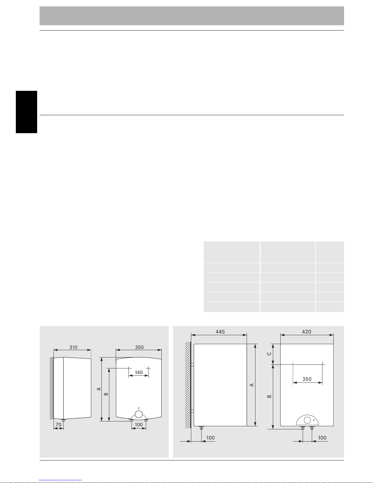
Die Wandspeicher WSE 15...100 Slim werden senkrecht mit den Anschlussstutzen
nach unten montiert und sollten so nah
wie möglich an der Zapfstelle angebracht
werden. So werden unnötige Wärmeverluste durch lange Rohrleitungen vermieden
und die Einstellbarkeit der gewünschten
Wassertemperatur verbessert.
Halten Sie für Wartungsarbeiten und eventuelle Reparaturen einen Platz von mindestens 50 cm unter dem Abgang der Rohrleitungen frei.
Zur Befestigung des Wandspeichers müssen Dübel und Schrauben verwendet werden, die dem Gewicht des Speichers mit
gefülltem Behälter Rechnung tragen (s.
Technische Daten, S. 5). Beachten Sie
bitte, daß die vorgesehene Wand ausreichend tragfähig ist!
WSE 15 Slim: Zur Befestigung sind zwei
Schrauben entsprechend den Maßen nach
Bild1 und Tab. 1 in der Wand zu verankern.
Danach wird der Speicher mit den an der
Rückwand befindlichen Ösen auf den
Schrauben eingehängt.
WSE 30...100 Slim: Die Lage der für die
Anbringung erforderlichen Schrauben ist
Bild 2 zu entnehmen. Die Wandbefestigung
ist in die Rückseite des Speichers integriert.
Tabelle 1Tabelle 1
Tabelle 1Tabelle 1
Tabelle 1
WSE 15 Slim:WSE 15 Slim:
WSE 15 Slim:WSE 15 Slim:
WSE 30...100 Slim:WSE 30...100 Slim:
WSE 30...100 Slim:WSE 30...100 Slim:
WANDMONTWANDMONT
WANDMONTWANDMONT
WANDMONTA GE
AA
AA GE
GE
GEGE
Modell A B C
(mm) (mm) (mm)
WSE 15 Slim 500 398 WSE 30 Slim 510 310 235
WSE 50 Slim 690 470 250
WSE 80 Slim 950 735 245
WSE 100 Slim 1125 900 255
– 2 –
D
Bild 1:Bild 1:
Bild 1:Bild 1:
Bild 1: WSE 15 Slim
Bild 2:Bild 2:
Bild 2:Bild 2:
Bild 2: WSE 30 Slim ... WSE 100 Slim
Page 3
– 3 –
raturzwecke entleert werden. Das Sicherheitsventil muss regelmäßig in gewissen
Abständen betätigt werden, um einem
Festsitzen durch Kalkablagerungen vorzubeugen.
DasAbflussrohrdesSicherheitsventilsmuss
immer zur Atmosphäre hin geöffnet bleiben.
Das durch den Druckanstieg beim Aufheizen
austretende Wasser muss über einen Ablauftrichter und ein Abflussrohr mit Gefälle,
das einen unbehinderten Ablauf des Wassers garantiert, abgeführt werden.
Ist der Wasserdruck höher als 5 bar, so
muss ein Druckminderer installiert werden. Ansonsten besteht die Gefahr, dass
das Sicherheitsventil anspricht und nicht
wieder schließt.
Installation: Das unbedingt
benötigte Sicherheitsventil
gehört nicht zum Lieferumfang des Speichers. Bei der
Montage beachten Sie bitte
die dem Ventil beiliegenden
Hinweise.
Vor Anschluss des Speichers
an die Wasserleitung ist diese gründlich durchzuspülen,
damit keine Fremdkörper in
den Speicher oder die Sicherheitsbaugruppe gelangen.
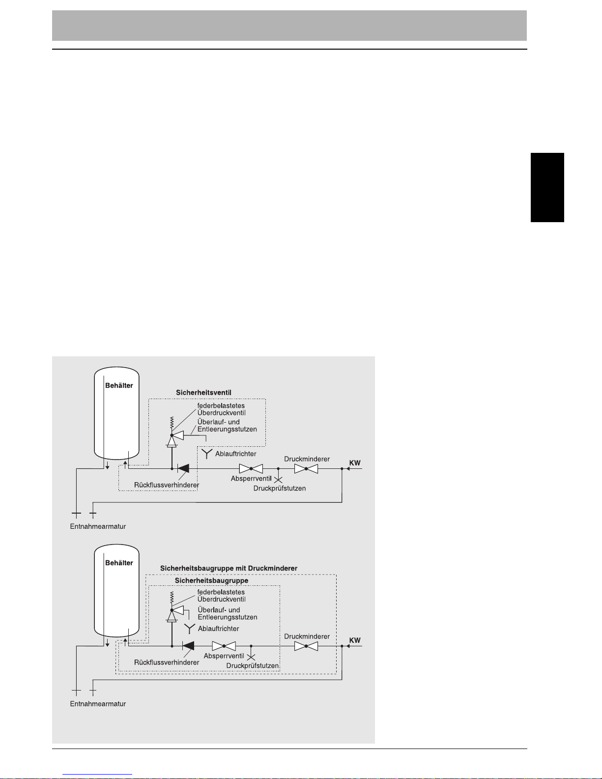
Speicher nach Schema in
Bild 3 installieren.
Auf Wunsch können ab Werk
Sicherheitsbaugruppen mit
oder ohne Druckminderer geliefert werden, die nach Bild 3
installiert werden.
Zur Montage und Handhabung der Sicherheitsbaugruppe lesen Sie bitte die der
Sicherheitsbaugruppe beiliegende Anleitung.
Wasseranschluss
Wichtige Hinweise zur Installation: Die
Wasserinstallation ist nach DIN 1988
„Technische Regeln für die Trinkwasserinstallation (TRWI)“
und DIN 4753
„Wassererwärmungsanlagen für Trink- und Betriebswasser“
auszuführen.
Der Speicher muss unbedingt mit einem
bauartgeprüften Sicherheitsventil installiert werden! Dieses Sicherheitsventil
schützt den Speicher vor unzulässig hohem Druckanstieg. Außerdem verhindert
es bei fehlendem Wasserdruck den Rückfluss des Speicherinhaltes in die Zuleitung.
Durch Öffnen des Sicherheitsventils (siehe
Montageanleitung der Sicherheitsbaugruppe) kann der Speicher bei geschlossenem Absperrventil für Wartungs- und Repa-
Ist der Wasserdruck höher als 5 bar, soIst der Wasserdruck höher als 5 bar, so
Ist der Wasserdruck höher als 5 bar, soIst der Wasserdruck höher als 5 bar, so
muss ein Druckminderer installiert wer-muss ein Druckminderer installiert wer-
muss ein Druckminderer installiert wer-muss ein Druckminderer installiert werden.den.
den.den.
Installation:Installation:
Installation:Installation:
nichtnicht
nichtnicht
WasseranschlussWasseranschluss
WasseranschlussWasseranschluss
Wichtige Hinweise zur Installation:Wichtige Hinweise zur Installation:
Wichtige Hinweise zur Installation:Wichtige Hinweise zur Installation:
Der Speicher muss unbedingt mit einemDer Speicher muss unbedingt mit einem
Der Speicher muss unbedingt mit einemDer Speicher muss unbedingt mit einem
bauartgeprüften Sicherheitsventil instal-bauartgeprüften Sicherheitsventil instal-
bauartgeprüften Sicherheitsventil instal-bauartgeprüften Sicherheitsventil installiert werden!liert werden!
liert werden!liert werden!
WASSERANSCWASSERANSC
WASSERANSCWASSERANSCHL
WASSERANSCHLUSS
HL
HLHLUSS
USS
USSUSS
Bild 3:Bild 3:
Bild 3:Bild 3:
Bild 3: Wasserinstallation mit Sicherheitsventil (oben) oder
Sicherheitsbaugruppe (unten)
D
Page 4
– 4 –
Füllen: Nach Anschluss des Heißwasserspeichers das Absperrventil öffnen. Anschließend Warmwasserhahn öffnen. Wenn
aus diesem Wasser austritt, ist der Speicher gefüllt. Dann den Auslaufhahn schließen und Anlage auf Dichtheit überprüfen.
Den Heißwasserspeicher auf keinen Fall
an das elektrische Netz anschließen,
ohne zu überprüfen, ob er tatsächlich
vollständig mit Wasser gefüllt ist!
Elektrischer Anschluss
Der elektrische Anschluss ist nach VDE
0100 „Bestimmungen für das Errichten
von Starkstromanlagen mit Nennspannungen bis 1000 V“ und den Vorschriften
des örtlichen Energieversorgungsunternehmens (EVU) auszuführen. Der elektrische Anschluss darf nur an einer ordnungsgemäß installierten Schutzkontaktsteckdose erfolgen.
Bei Festanschluss muss in der Zuleitung
allpolig eine Trennstrecke von mindestens
3 mm Kontaktabstand (z.B. Sicherung)
vorhanden sein.
Dieser elektrische Anschluss muss durch
einen zugelassenen Fachmann erfolgen.
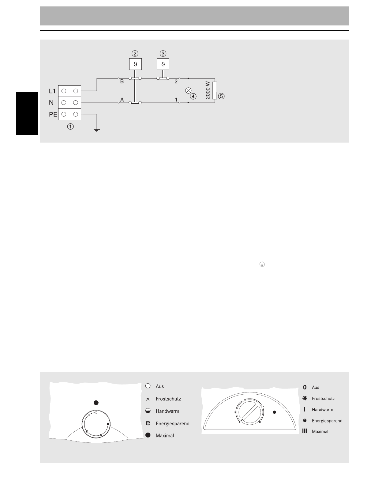
Nach Abnahme des Deckels ist das Netzkabel durch die Kabeleinführung an der
Geräteunterseite zu führen und mit der
Zugentlastungsschelle zu befestigen. Danach erfolgt der Anschluss an den Klemmen L1, N und
Dieser elektrische Anschluss muss durchDieser elektrische Anschluss muss durch
Dieser elektrische Anschluss muss durchDieser elektrische Anschluss muss durch
einen zugelassenen Fachmann erfolgen.einen zugelassenen Fachmann erfolgen.
einen zugelassenen Fachmann erfolgen.einen zugelassenen Fachmann erfolgen.
(PE) (siehe Bild 4).
InbetriebnahmeInbetriebnahme
InbetriebnahmeInbetriebnahme
Inbetriebnahme
Die erste Inbetriebnahme und Aufheizung
muss der Fachmann überwachen
Die Wassertemperatur kann an einem au-
ßen befindlichen Reglerknopf zwischen
ungefähr 25 °C (Minimum) und 75 °C
(Maximum) eingestellt werden (siehe
Bild 5).
D
Füllen:Füllen:
Füllen:Füllen:
Den Heißwasserspeicher auf keinen FallDen Heißwasserspeicher auf keinen Fall
Den Heißwasserspeicher auf keinen FallDen Heißwasserspeicher auf keinen Fall
an das elektrische Netz anschließen,an das elektrische Netz anschließen,
an das elektrische Netz anschließen,an das elektrische Netz anschließen,
ohne zu überprüfen, ob er tatsächlichohne zu überprüfen, ob er tatsächlich
ohne zu überprüfen, ob er tatsächlichohne zu überprüfen, ob er tatsächlich
vollständig mit Wasser gefüllt ist!vollständig mit Wasser gefüllt ist!
vollständig mit Wasser gefüllt ist!vollständig mit Wasser gefüllt ist!
Elektrischer AnschlussElektrischer Anschluss
Elektrischer AnschlussElektrischer Anschluss
Der elektri-Der elektri-
Der elektri-Der elektri-
sche Anschluss darf nur an einer ord-sche Anschluss darf nur an einer ord-
sche Anschluss darf nur an einer ord-sche Anschluss darf nur an einer ordnungsgemäß installierten Schutzkon-nungsgemäß installierten Schutzkon-
nungsgemäß installierten Schutzkon-nungsgemäß installierten Schutzkontaktsteckdose erfolgen.taktsteckdose erfolgen.
taktsteckdose erfolgen.taktsteckdose erfolgen.
ELEKELEK
ELEKELEK TRISC
ELEKTRISCHER ANSCHLUSS
TRISC
TRISCTRISC
HER ANSC
HER ANSC
HER ANSCHER ANSC HL
HL
HLHLUSS
USS
USSUSS INBETRIEBN
INBETRIEBN
INBETRIEBNINBETRIEBNAHME
INBETRIEBNAHME
AHME
AHMEAHME
Bild 5:Bild 5:
Bild 5:Bild 5:
Bild 5: Bedienblende für WSE 15 Slim (links) und WSE 30 Slim ... WSE 100 Slim (rechts)
1 Klemmleiste
2 Sicherheits-
temperaturbegrenzer
3 Thermostat
4 Signallampe
5 Heizkörper
Bild 4:Bild 4:
Bild 4:Bild 4:
Bild 4: Schaltplan
Page 5

TECTEC
TECTECHNISC
TECHNISCHE DATEN
HNISC
HNISCHNISC
HE D
HE D
HE DHE D AAAA
TENTEN
TENTEN
– 5 –
D
ee
ee
fließt. Wenn ständig Wasser aus dem
Abflussrohr der Sicherheitsbaugruppe austritt, muss ein Druckminderer installiert
werden (siehe oben).
Es ist ratsam, den Speicher nur bei längerer Abwesenheit vom Netz zu trennen.
Durch die hochwertige Wärmedämmung
aus FCKW-freiem Polyurethanschaum ist
der Wärmeverlust nur unbedeutend.
Bei Frostgefahr ist der Speicher bei geschlossenem Absperrventil über das
Entleerungsventil an der Sicherheitsbaugruppe zu entleeren.
Bei geringerem Warmwasserverbrauch
oder bei stark kalkhaltigem Wasser empfiehlt sich die Energiesparstellung „ e“ bei
ca. 60 °C. In bestimmten Zeitabständen
oder nach Entnahme von Warmwasser heizt
das Gerät automatisch nach; der Heizvorgang wird durch die Signallampe angezeigt.
Beim Aufheizen des Speichers entsteht
infolge Volumenzunahme des Wasserinhaltes ein Druckanstieg. Wenn der Nenndruck der Sicherheitsbaugruppe dabei
überschritten wird, öffnet das Ventil, wobei etwas Wasser in den Ablauftrichter
TTTTecec
ecechnisc
hnisc
hnischnisc
he Dat
he Dat
he Dathe Datenenenen
Model WSE 15 WSE 30 WSE 50 WSE 80 WSE 100
Slim Slim Slim Slim Slim
Volumen (l) 15 30 50 80 100
Nenndruck (MPa) 0,6
Gewicht leer/gefüllt
mit Wasser (kg) 11/26 19/49 24/74 31/111 36/136
Korrosionsschutz Emaillierung & Magnesiumschutzanode
Leistungsaufnahme (W) 2000
Anschlussspannung (V) 230
Schutzklase I
Schutzgrad IP 24
Aufheizzeit
bis 75 °C
1)
(min) 33 65 115 185 235
Mischwassermenge bei 40 °C (l) 27 58 94 148 194
Bereitschaftsstromverbrauch
2)
(kWh/d) 0,40 0,90 0,99 1,26 1,71
Technische Daten
1) Aufheizzeit des gefüllten Behälters bei einer Eintrittstemperatur des kalten Wassers von 15 °C
2) Energieverbrauch bei konstanter Wassertemperatur von 65 °C bei einer Umgebungstemperatur
von 20 °C, gemessen nach DIN 44532
Page 6

WW
WWARARTUNG, KUNDENDIENST , GARANTIEBEDINGUNGENT
WARTUNG, KUNDENDIENST, GARANTIEBEDINGUNGEN
ARTUNG, KUNDENDIENS
AR
TUNG, KUNDENDIENS
TUNG, KUNDENDIENS T
T , GARANTIEBEDINGUNGEN, GARANTIEBEDINGUNGEN
, GARANTIEBEDINGUNGEN
– 6 –
WW
WWar
ar tung
arartungtungtung
Achtung! Vor Lösen des Anschluss-Achtung! Vor Lösen des Anschluss-
Achtung! Vor Lösen des Anschluss-Achtung! Vor Lösen des Anschlussdeckels muss das Gerät immer span-deckels muss das Gerät immer span-
deckels muss das Gerät immer span-deckels muss das Gerät immer spannungsfrei geschaltet werden!nungsfrei geschaltet werden!
nungsfrei geschaltet werden!nungsfrei geschaltet werden!
KK
Kundendiens K
undendiens
undendiens
undendienst
t
t
GarGar
GarGarantiebedingung
antiebedingung
antiebedingungantiebedingung
en
enen
Irrtümer und technische Änderungen vorbehalten. Abmessungen ohne Gewähr.
t
Wartung
Das Äußere des Speichers erfordert keine
besondere Wartung. Zur Reinigung nur mit
einem weichen Lappen oder feuchten
Schwamm abreiben, keine Scheuermittel
verwenden!
Zur Sicherung einer langen Lebensdauer
empfiehlt es sich, die im Gerät installierte
Korrosionschutz-Anode (Magnesium-Anode) einer jährlichen Inspektion durch einen Fachmann unterziehen zu lassen. In
Gebieten mit besonders aggressivem Was-
ser kann diese Prüfung häufiger notwen-
dig sein — dazu entsprechende Informationen vom Installateur oder direkt beim
Wasserversorgungsunternehmen einholen!
Vor einem übermäßigen Erhitzen des Wassers bei einem eventuellen Ausfall des
Thermostaten ist das Gerät durch einen
zweipoligen Sicherheitstemperaturbegrenzer geschützt, der beide Leitungen
unterbricht. Wenn der Sicherheitstemperaturbegrenzer ausgelöst wurde, ist
ein autorisierter Fachmann zur Durchfüh-
rung der Reparatur hinzuzuziehen.
Achtung! Vor Lösen des Anschlussdeckels muss das Gerät immer spannungsfrei geschaltet werden!
Kundendienst
en
Die Firma Lucht LHZ Elektroheizung GmbH & Co. KG übernimmt unabhängig von den
Verplichtungen des Verkäufers gegenüber dem Käufer für dieses Gerät eine Garantie
von 24 Monaten ab Verkaufsdatum.
Innerhalb der Garantie werden alle Mängel, die auf Material- oder Herstellungsfehler
zurückzuführen sind, kostenlos beseitigt. Über die kostenlose Fehlerbeseitigung hinausgehende Ansprüche können im Rahmen der Garantie nicht geltend gemacht werden. Unsere
Garantieleistungen setzen voraus, daß der Heißwasserspeicher ordnungsgemäß mit der
vorgeschriebenen Sicherheitsbaugruppe betrieben wurde.
Der Garantieanspruch erlischt, wenn nicht fachgerechte Reparaturen oder Eingriffe in das
Gerät vorgenommen wurden. Schäden, die durch unsachgemäßen Gebrauch, durch falsche
Aufbewahrung oder unsachgemäßen Transport, durch unsachgemäße Installation sowie
durch höhere Gewalt oder sonstige äußere Einflüsse entstehen, fallen nicht unter die
Garantie.
Wir behalten uns vor, bei auftretenden Mängeln defekte Teile auszutauschen. Ausgetauschte Teile oder Geräte gehen in unser Eigentum über.
Bei einer eventuell erforderlichen Reparatur wenden Sie sich bitte an Ihren Installateur/
Händler, bei dem Sie das Gerät erworben haben.
Garantiebedingung en
D
Page 7

WALL MOUNTINGWALL MOUNTING
WALL MOUNTINGWALL MOUNTING
WALL MOUNTING
– 7 –
GB
Dear customer!
we hope the new thermal storage water heater will give you great pleasure. This appliance
offers high operating convenience and energy-saving operation. Please make yourselves
acquainted with the correct mounting, initiation, operation and maintenance before use.
Please make sure that the appliance is installed by a qualified specialist.
In the following we will give you the necessary instructions:
WW
WW
all mounting
Wall mounting
The wall-mounted storage water heaters
WSE 15...100 Slim must be installed in a
vertical position with the connecting
branches pointing downwards. They should
be installed as close to a water tap as
possible. That way unnecessary heat losses
caused by long pipes will be avoided and
the adjustability of the desired water temperature improved.
For maintenance work and possible repairs, please keep clear a minimum space
of 50 cm underneath the exit of the pipe
lines.
In order to fasten the wall-mounted stor-
age water heater it is necessary to use
dowels and screws suitable for the weight
of the storage water heater including a full
tank (refer to Technical Data, p. 10). Please
make sure that the carrying capacity of the
wall intended to hold the storage water
heater is large enough.
all mounting
all mountingall mounting
WSE 15 Slim:WSE 15 Slim:
WSE 15 Slim:WSE 15 Slim:
WSE 15 Slim: In order to fasten the wallmounted storage water heater two screws
are to be attached to the wall according to
table 1 and figure 1. The storage water
heater is hung up on the screws using the
eyelets on the back panel.
WSE 30...100 Slim: The position for attaching the necessary screws is shown in
figure 2. The wall fixing element is a component of the storage water heater.
WSE 30...100 Slim:WSE 30...100 Slim:
WSE 30...100 Slim:WSE 30...100 Slim:
Table 1Table 1
Table 1Table 1
Table 1
Fig. 2: WSE 30 Slim ... WSE 100 Slim
Fig. 2:Fig. 2:
Fig. 2:Fig. 2:
Model A B C
(mm) (mm) (mm)
WSE 15 Slim 500 398 WSE 30 Slim 510 310 235
WSE 50 Slim 690 470 250
WSE 80 Slim 950 735 245
WSE 100 Slim 1125 900 255
Fig. 1:Fig. 1:
Fig. 1:Fig. 1:
Fig. 1: WSE 15 Slim
Page 8

WW
WW A
WATER SUPPLY
AAATER SUPPLTER SUPPL
TER SUPPLTER SUPPLYYYY
– 8 –
W
Water Supply
Water Supply
Important instructions for installation:
The water supply installation is to be carried out according to DIN 1988
WW atatat
er Suppl
er Suppler Suppl yyy
Important instructions for installation:Important instructions for installation:
Important instructions for installation:Important instructions for installation:
“Technical
Rules for Drinking Water Installation
(TRWI)”
, DIN 4753
“Water heating installa-
tions for drinking and service water”
and/
or the national standards which may apply.
It is absolutely necessary to install the
storage water heater equipped with a
design-approved safety module. This
safety module protects the storage water
heater from an inadmissible increase of
pressure. In addition, it prevents the contents of the storage water heater from
flowing back into the feeding pipe in the
case of insufficient water pressure. For
maintenance and repair purposes, it is
It is absolutely necessary to install theIt is absolutely necessary to install the
It is absolutely necessary to install theIt is absolutely necessary to install the
storage water heater equipped with astorage water heater equipped with a
storage water heater equipped with astorage water heater equipped with a
design-approved safety module.design-approved safety module.
design-approved safety module.design-approved safety module.
possible to empty the storage water heater
with the closed stop valve by opening the
safety valve (refer to mounting instructions of the safety module). The safety
valve must be activated regularly at certain intervals in order to prevent it from
getting stuck due to calcium deposits.
The discharge pipe of the safety module
must always stay open towards the atmosphere. Outflowing water, caused by the
increasing pressure by heating, has to rinse
through a funnel connected to a discharge
pipe keeping a constant inclination that
guarantees an unhindered outflow of water.
If the water pressure is higher than
5 bar, it is necessary to install a safety
module with pressure reducer. Otherwise there is a danger that the pressure
If the water pressure is higher thanIf the water pressure is higher than
If the water pressure is higher thanIf the water pressure is higher than
5 bar5 bar
5 bar5 bar
, it is necessary to install a safety
, it is necessary to install a safety
, it is necessary to install a safety, it is necessary to install a safety
module with pressure reducer.module with pressure reducer.
module with pressure reducer.module with pressure reducer.
control valve of the safety
module responds and does
not close afterwards.
Installation: The absolutely
necessary safety valve is not
shipped together with the
storage water heater. For
mounting read the instructions enclosed with the safety
valve, please.
Before connecting the storage water heater to the water pipe, the pipe should be
rinsed thoroughly in order to
avoid impurities getting into
the storage water heater or
into the safety module.
Install the storage water
heater according to the diagram in figure 3.
If desired, it is possible to
deliver ex works safety modules with or without pressure
reducer, for mounting refer
to figure 3.
Installation:Installation:
Installation:Installation:
notnot
notnot
Fig. 3: Installation schema for installation with safety valve
(top) or safety modul (below)
Fig. 3:Fig. 3:
Fig. 3:Fig. 3:
GB
Page 9

ELECTRIC CONNECTIONELECTRIC CONNECTION
ELECTRIC CONNECTIONELECTRIC CONNECTION INITIA
ELECTRIC CONNECTION
INITIA
INITIAINITIA
INITIATION
TIONTION
TIONTION
– 9 –
GB
We ask you to read the instructions enclosed with the safety module for mounting and handling the safety module.
Filling: Having connected the thermal storage water heater, open the stop valve.
Then open the hot-water tap. When water
comes from this tap, the storage water
heater is filled. Then close the drain cock
and check that the installation is leakproof.
Never connect the thermal storage water heater to the electric mains without
checking whether it is really completely
filled with water!
Electric connection
The electric connection is to be carried out
according to VDE 0100 “Regulations for
the erection of power installations with
nominal voltages up to 1000 V” and the
regulations of the local electric supply
company (EVU). The electric connection
of the appliance may only be carried out
using a shockproof socket installed according to safety regulations.
For fixed connections, an all-pole switch
with an air gap of at least 3 mm contact
clearance (e.g. safety fuse) must be installed fixed in the power supply. This
electric connection must be made by a
licensed specialist.
Filling:Filling:
Filling:Filling:
Never connect the thermal storage wa-Never connect the thermal storage wa-
Never connect the thermal storage wa-Never connect the thermal storage water heater to the electric mains withoutter heater to the electric mains without
ter heater to the electric mains withoutter heater to the electric mains without
checking whether it is really completelychecking whether it is really completely
checking whether it is really completelychecking whether it is really completely
filled with water!filled with water!
filled with water!filled with water!
ElectrElectr
ElectrElectr
ic connection
ic connection
ic connectionic connection
The electric connectionThe electric connection
The electric connectionThe electric connection
of the appliance may only be carried outof the appliance may only be carried out
of the appliance may only be carried outof the appliance may only be carried out
using a shockproof socket installed ac-using a shockproof socket installed ac-
using a shockproof socket installed ac-using a shockproof socket installed according to safety regulations.cording to safety regulations.
cording to safety regulations.cording to safety regulations.
ThisThis
ThisThis
electric connection must be made by aelectric connection must be made by a
electric connection must be made by aelectric connection must be made by a
licensed specialist.licensed specialist.
licensed specialist.licensed specialist.
Having removed the cover, the mains cable
must be led through the cable entry at the
bottom side of the appliance and must be
fastened using the strain relief strap. Then
the connection to the binders L1, N and
(PE) has to be made (refer to figure 4).
InitiationInitiation
InitiationInitiation
Initiation
A specialist must supervise the first initiation and the heating-up.
The water temperature can be set between approx. 25 °C (minimum) and 75 °C
(maximum) using a control knob located
outside (see figure 5).
When the water consumption is low or the
water is highly calcareous it is recommended to use the power saving position
“ e” at approx. 60 °C. The appliance will
reheat automatically at certain intervals or
after hot water has been taken; the heating operation is indicated by the pilot lamp.
When heating up the storage water, the
pressure inside rises as a result of the
volume increase. When the nominal pressure of the safety module is exceeded, the
valve opens and some water flows into the
discharge funnel. If water flows constantly
from the discharge pipe of the safety module, a pressure reducer must be installed
(as mentioned above).
e”e”
e”e”
1 Connection terminal
2 Safety temperature
limiter
3 Thermostat
4 Pilot lamp
5 Heater
Fig. 4:Fig. 4:
Fig. 4:Fig. 4:
Fig. 4: Circuit diagram
Page 10

SPECIFICSPECIFIC
SPECIFICSPECIFICA
SPECIFICATIONS
AAATIONSTIONS
TIONSTIONS
– 10 –
Fig. 5:Fig. 5:
Fig. 5:Fig. 5:
TT
TT
Technical Data
ecec
ecec
hnical Dat
hnical Dat
hnical Dathnical Dat aaaa
1) The time needed for heating-up the filled tank, starting with a cold water temperature of 15 °C
2) The energy consumption for a constant water temperature of 65 °C at an environment temperature
of 20 °C, measured according to DIN 44532
GB
When there is danger of frost, the storage
water heater must be emptied by means of
the drain valve at the safety module with
the stop valve being closed.
It is advisable not to separate the storage
water heater from the mains except during
fairly long absences. Due to the high-quality thermal insulation made of CFC-free
polyurethane rigid foam, the heat loss is
insignificant.
Fig. 5: Control panel for the model WSE 15 Slim (left)
and the models WSE 30 Slim ... WSE 100 Slim (right)
Model WSE 15 WSE 30 WSE 50 WSE 80 WSE 100
Slim Slim Slim Slim Slim
Capacity (l) 15 30 50 80 100
Nom. pressure (MPa) 0,6
Weight empty/filled
with water (kg) 11/26 19/49 24/74 31/111 36/136
Corrosion protection enamaled tank + magnesium anode
Power consumption (W) 2000
Supply voltage (V) 230
Protecting class I
Protecting type splash water proof
Time needed for heating-
up to 75 °C
1)
(min) 33 65 115 185 235
Mix water capacity
at 40 °C (l) 27 58 94 148 194
Stand-by
consumption
2)
(kWh/d) 0,40 0,90 0,99 1,26 1,71
Page 11

Caution! Before loosening the contact
lid, it is always necessary to switch the
appliance into a voltage-free state!
MaintMaint
MaintMaintenance
Maint
The outside of the storage water heater
does not require any special maintenance.
For cleaning purposes, merely rub it off
with a smooth cloth or a damp sponge. Do
not use any scouring agents or detergents.
In order to ensure a long life it is recommended to ask a specialist to inspect the
anticorrosive anode (magnesium anode)
installed within the appliance at annual
intervals. In regions with particularly aggressive water it may be necessary to
carry out this examination more frequently
- consult the plumber or the water supply
company for appropriate information!
Should the thermostat fail, the appliance
will be protected from excessive heating of
the water by means of a safety temperature limiter that interrupts all phases. If the
safety temperature limiter should be triggered, an authorized specialist must be
called in to carry out the repair.
enance
Caution! Before loosening the contact
lid, it is always necessary to switch the
appliance into a voltage-free state!
enance
enance
enance
Caution! Before loosening the contactCaution! Before loosening the contact
Caution! Before loosening the contact
lid, it is always necessary to switch thelid, it is always necessary to switch the
lid, it is always necessary to switch the
appliance into a voltage-free state!appliance into a voltage-free state!
appliance into a voltage-free state!
TT
TT
erms of guar antee
T
The terms of guarantee issued by the manufacturer’s agent in the country of purchase apply
to this device. Upon request and at any time the dealer who sold the device to you will inform
you about the concrete content of the terms. To be able to use guarantee services it is
absolutely necessary to present a receipt showing the date of purchase and bearing the
dealer’s stamp and signature.
erms of guarantee
er
er ms of guar
erms of guar
ms of guar
ant
ant
ant
ee
ee
ee
MAINTENMAINTEN
MAINTENMAINTENANCE
MAINTEN
ANCE
ANCE
ANCE
ANCE
GB
– 11 –
01.08.2013
Irrtümer und technische Änderungen vorbehalten. Abmessungen ohne Gewähr.
Lucht LHZ Elektroheizung GmbH & Co. KG
Obere Hauptstr. 61
09232 Hartmannsdorf
Fon: +49 (0) 3722 63370 E-mail: info@technotherm.de
Fax: +49 (0) 3722 633720 Web: www.technotherm.de
 Loading...