

Technotherm TTS 170 F, TTH 550, TTS 240, TTN 130 F, TTW 110 Installation And Technical Manual
...
1
D
THESE INSTRUCTIONS SHOULD BE READ CAREFULLY AND RETAINED FOR
FUTURE REFERENCE.
BE SURE TO OBSERVE ALL LABELS AND WARNINGS ON THE APPLIANCE
.
Edition:12/16
Id_Nr. 900 319 701
Installation and technical manual
Storage Heater with electronic control
GB
TTS 200
TTS 240 TTS 170 F TTN 300 TTN 130 F TTW 110 TTH 550
TTS 300 TTS 260 F TTN 400 TTN 200 F TTW 160
TTS 360 TTS 340 F TTN 500 TTN 270 F TTW 210
TTS 400 TTS 430 F TTN 330 F TTW 260
TTS 510 TTS 510 F TTN 400 F TTW 310
TTS 610
TTS 710
Including all_Eco-devices
Edition:10/14
2
Manual Storage Heater TTS wi th electronic control
GB
Contents
Introduction page 3
Safety page 4
Design and Construction page 5
Operation page 6 to 7
Installation page 8 to 13
Room Thermostats page 13
Technical Data page 14
Circuit Diagram page 19
Attention : The storage heater must only be installed by a competent electrician.
Edition:10/14
3
Manual Storage Heater TTS wi th electronic control
GB
Introduction
We congratulate you on your purchase of your Technotherm storage heater.
Although the Installation and Operation of the heater is very simple, we advise that you read
this booklet carefully as it gives you important information on safety, the installation and
operation, as well as the care of the appliance. Please retain the instructions and pass them
on to future occupants of the heated dwelling.
Please note the following:-
dispose of all packing materials in the
proper way.
if the heater shows any sign of damage, report it straight away, before installation!
chipped or slightly damaged bricks can be used without problem.
this heat er must only be installed and serviced by a qualified electrician.
Read all the information on the rating label and make sure that this corresponds to the
required values.
Edition:10/14
4
Manual Storage Heater TTS wi th electronic control
GB
Caution
Storage Heaters may become very hot!
Electric storage heaters are space heating appliances and will attain surface temperatures in
excess of 90°C (195°F) and greater directly in front of or above the discharge grille.
Do not create fire hazards by placing flammable objects, materials or substances on, against
or near the heater.
Keep the air discharge grille clear at all times and allow a 30 cm (12") clearance in front of
the heater, 3cm (1¼“) to the sides and top.
This manual must be read by the installing electrician prior to installation of the heater and by
the owner or occupant prior to operation of the heating system. Save this manual and pass it
on to any new owner or occupant. Should the heater(s) require service, provide this manual
to the service personnel.
This equipment is only for installation in accordance with current Electrical Codes. It should
only be installed by a competent, licensed electrician. Any deviation from these instructions
will result in voiding the warranty and may create a dangerous condition.
Description
How it works...
The concept is simple:
Use electricity when there is little demand for it (usually at night) so that the Electricity
Board can sell it at lower rates.
Turn this cheap electricity into heat which can be easily stored.
Store just enough heat to comfortably meet your daily needs.
Use the stored heat (but not electricity) during the rest of the day when electricity costs
much more because everybody else needs it (industries, businesses, schools and
homes).
Here is how your TTS Heating System does it:
The Electricity Board puts in a different type of electric meter which measures the electricity
you use during the "Off-Peak" hours on one set of dials and the "On-Peak" hours on another
set. Some utilities may, instead, provide a separate meter which measures only the electricity
used by the storage heaters. This will depend on the type of rate your Power Company
offers.
TTS heaters work the same way with any of these rates. When the meter switches at the
pre-set time or by command, from the high rate "On-Peak" to the low rate "Off-Peak", it
signals a control panel in the heating system to turn on the individual TTS heaters and begin
charging them up.
The temperature in each room is controlled independently by a thermostat (integral or wall
mounted) used to operate a small fan within the heater to discharge stored heat as needed.
No other heating system offers the precise combination of thermostat controlled convection
heat supported by a constant background of radiant heat emitted by the warm surfaces of the
heater case. No ups and downs in room temperature, just comfort at its best.
Edition:10/14
5
Manual Storage Heater TTS wi th electronic control
GB
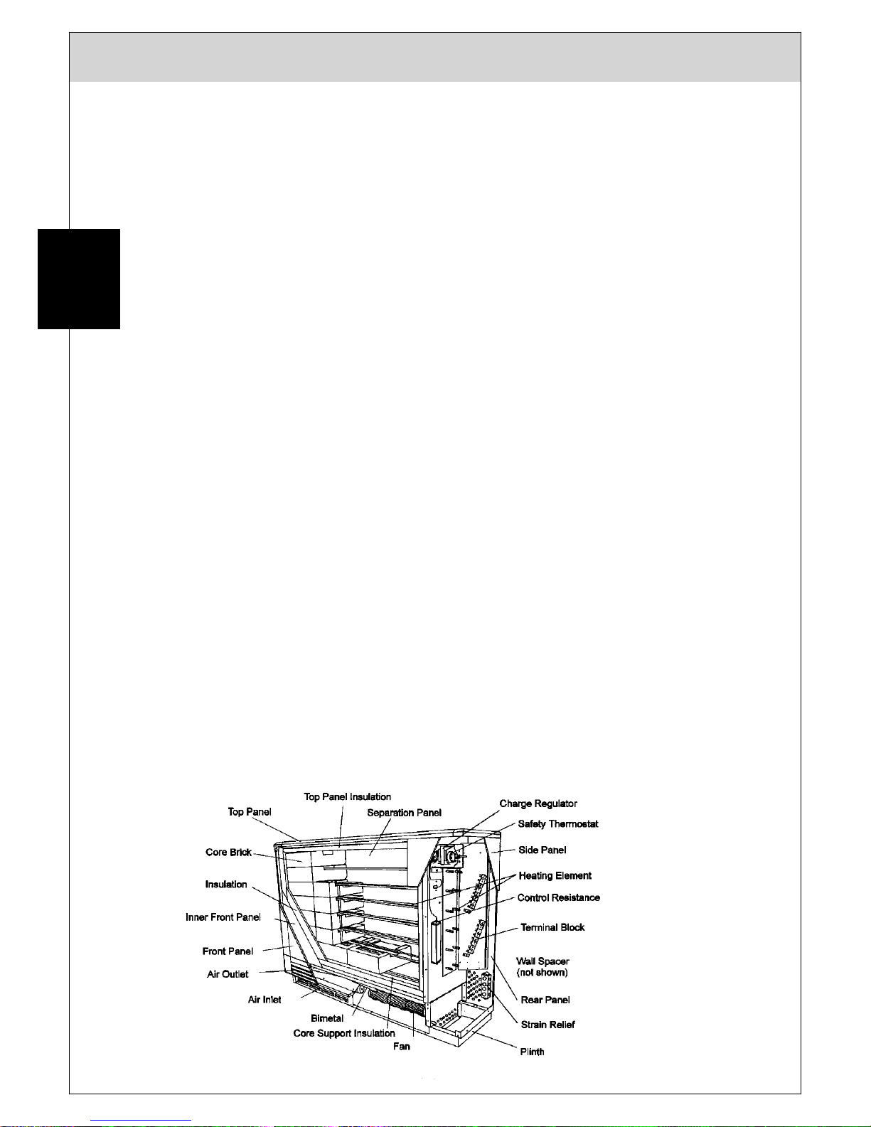
Design and Construction
TTS heaters are an assembly of 6 primary elements:
1. Case - The attractively designed steel case is finished with a high degree of
craftsmanship. All surfaces painted with a neutral off-white baked enamel. This case is
very strong and provides the base upon which all other components are supported.
2. Thermal Insulation - The thermal insulation within the heater provides a key function in
the heaters' design and is a combination of Vermiculite panels and a micro porous type
ceramic material. The result is the ability to store heat within the brick core at
temperatures reaching 675°C (1250°F) and yet provide surface temperatures on the
case which are typically below 75°C (165°F).
3. Storage Core - The actual heat storage device is an assembled core made up of
refractory bricks of feolite material, approx. 6 kg (13 lbs) each.
The bricks are identical and are delivered in packs of 2’s and 3’s (see Technical Data,
page 14).
The bricks are moulded, high temperature fired and specifically formulated to provide the
highest specific heat and thermal conductivity for the maximum efficiency as a storage
core.
4. Heating Elements - The electric heating elements are a metal sheath, rod type made of
the finest materials proven in millions of installations over the past 20 years. This
element placed within the special shaped storage bricks, provides for rapid heat
recovery and an even application of heat to the storage core.
5. Charge Controls - TTS heaters are equipped with two separate thermostat controls, the
first is the "Manual" charge thermostat which can be fitted with a control knob at the front
of the heater. This control is used to manually set the temperature level that the heater
storage core will be charged to during each charge period, and thus the amount of heat
stored. The second charge control is a fixed setting "Safety" or high temperature limit
thermostat which will shut the heater off if the other controls fail to limit the maximum
temperatures.
6. Fan Assembly - The TTS heater utilizes a low-volume, slow speed fan to push heat
from the storage core when the wall thermostat signals the need for heat in the room.
The fan assembly also includes the discharge air mixing valve used to keep the output
air temperature at a safe and comfortable level. TTS heater fans are nearly silent in
normal operation and should not cause concern even in bedroom applications.
Edition:10/14
6
Manual Storage Heater TTS wi th electronic control
GB
Operating Instructions
The operation of TTS heaters is convenient and economical. The heaters charge over night.
Radiation from the casing provides a low level of background heat. The fan can be switched
on as desired increasing heat output.
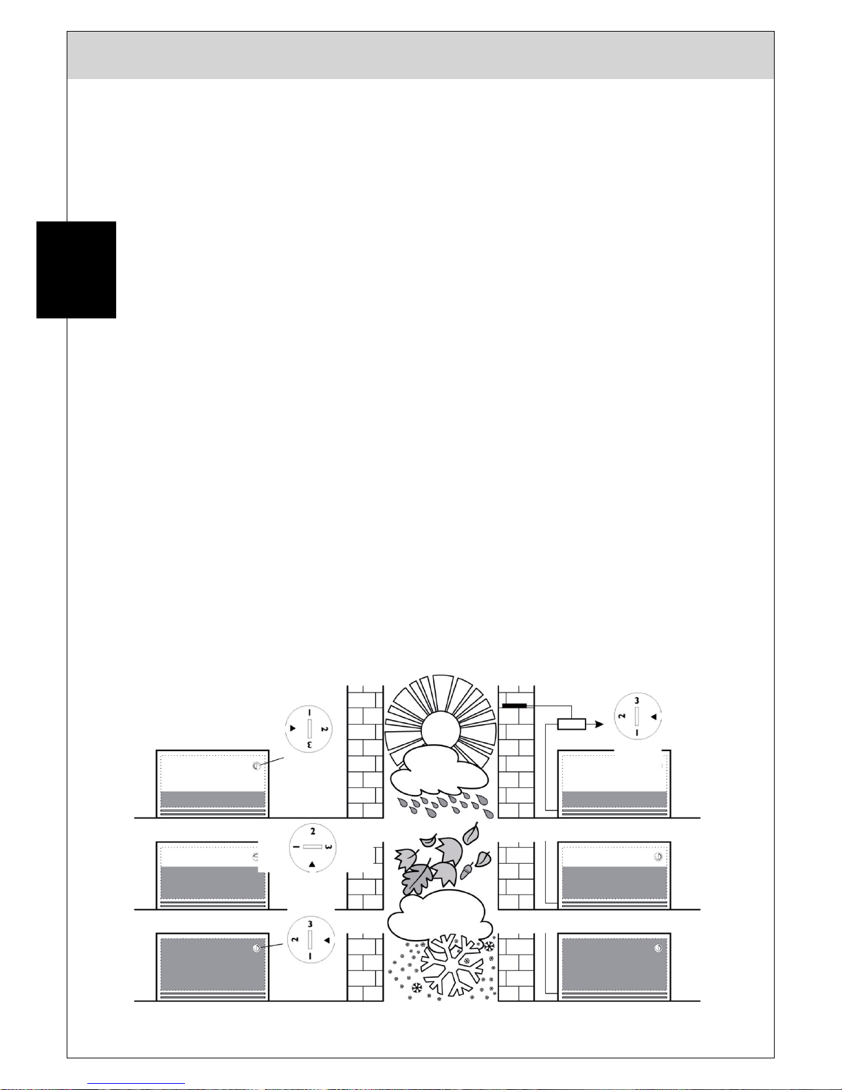
Heater Charging Adjustments
TTS heater charging can be controlled either automatically or manually.
Automatic Control
The most common method of control for heating systems consisting of three or more heaters
is an automatic charge control. This control uses a weather (outdoor temperature) sensor to
set the maximum charge level and sends a signal to the heater. At the heater, residual heat
left over from the last charge cycle is compared and the maximum charge setting is adjusted.
When an automatic charge control is provided, there is normally no need for manual
adjustment unless an individual heater is oversized for the space. The manual adjustment
does, however, provide a convenient method of reducing the heat output in unoccupied
rooms or rooms where heating requirements vary, such as bedrooms, etc.
Manual Control
When only "Manual" adjustment of the TTS heater is needed, the exterior mounted control
knob must be installed. This is the knob that was found in the cardboard shipping support
used between the heater elements. The heater's thermal charge level can now be adjusted
by a simple turn of the knob.
Suggested knob settings for maximum heating comfort and efficiency are:
Summer weather No charge
Cool weather 1/3 charge
Cold weather 2/3 charge
Very cold weather Full charge

Edition:10/14
7
Manual Storage Heater TTS wi th electronic control
GB
Output Control
A proportion of the stored heat will be radiated from the casing providing a low level of
background heat. Output can be increased by switching on the fan(s) whereby heat is
discharged from the low level outlet grille.
This is done at the room thermostat located on the wall facing the heater. If the thermostat is
provided with an "ON-OFF" switch for the fan(s) set this switch to "ON". Then turn the
thermostat knob to the desired room temperature indicated on the dial. Once set, the
thermostat will then keep the room temperature automatically at this level by switching the
fan(s) on and off accordingly.
Integral Thermostat
TTS storage heaters are designed to use an integral thermostat as an optional accessory.
This is often of advantage when retrofitting storage heat into existing buildings as it
eliminates the need for wiring between a wall thermostat and the heater.
The accessory kit comprises a side panel complete with pre-wired thermostat and rocker
switch assembly.
Care of the Storage Heater
TTS storage heaters are designed to require minimum maintenance. The surface (when
cool) can be cleaned with any "liquid" household cleaner.
Note - Do not use abrasive cleaners as these may damage the finish.
In those areas where considerable amounts of dust, dirt and/or fur are encountered, it is
recommended that the area behind and in front of the heater be vacuumed quite frequently.
The fan assembly and base compartment should be completely cleaned at least every three
years just before a heating season.
Electrical Shock Hazard
TTS heaters are supplied by more than one electrical circuit.
Be sure that all circuits are turned off before opening the heater case.
Service should only be made by competent, qualified personnel.

Edition:10/14
8
Manual Storage Heater TTS wi th electronic control
GB
Installation
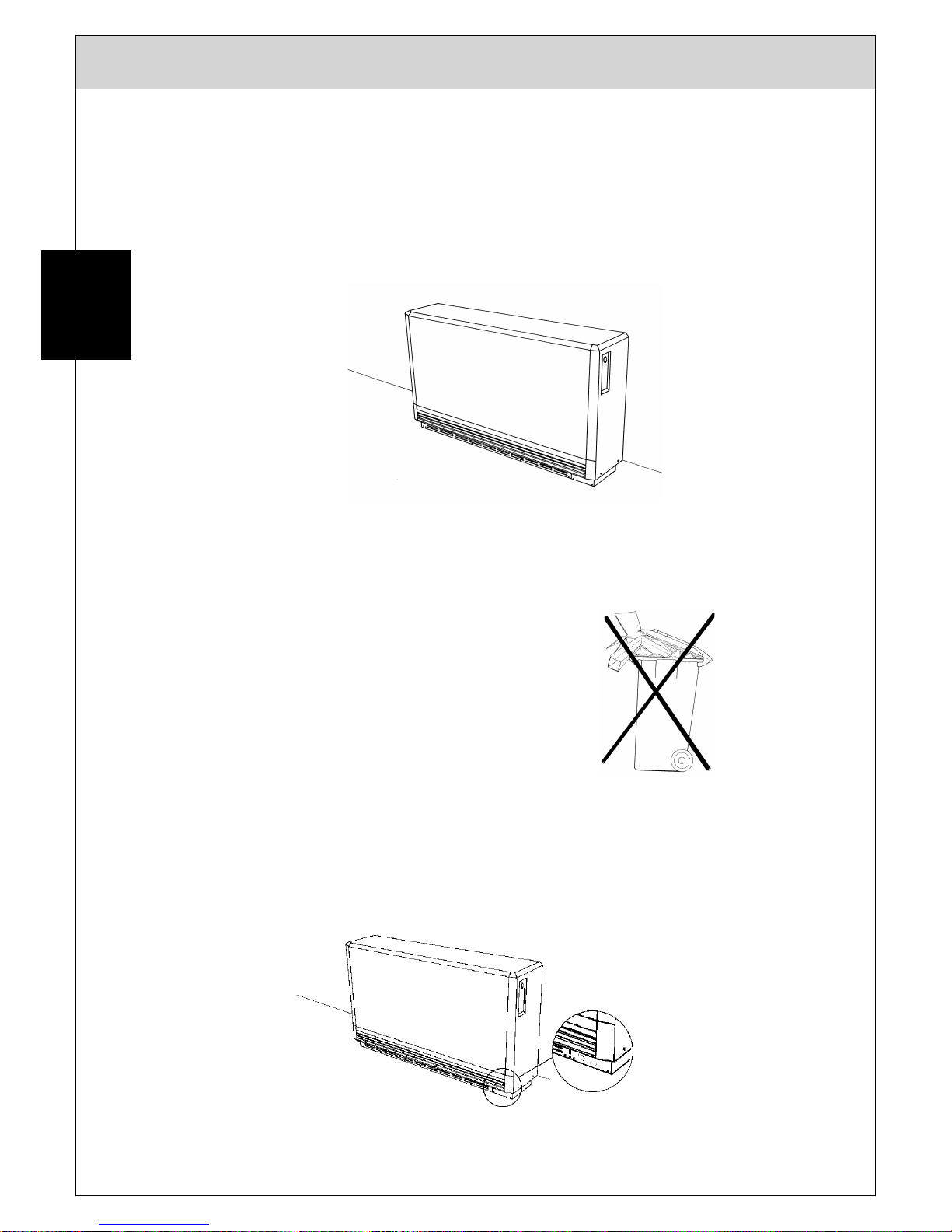
Positioning
Please read the instructions in the introductory section concerning position, safety and loadbearing capacity.
If in doubt, consult a building engineer.
Transport
To facilitate transport, the heater and the bricks are packaged separately. The 7 bricks per
core column are packed in two’s and three’s.
The heating elements are factory fitted and pre-wired.
Preparation
In order to avoid unnecessary scratching
or other damage to the heater it is advised
to unpack it close to its proposed place of
installation.
Tip the carton on its back and remove the
screws from the wooden palette to which
the base of the heater is attached.
Bring the carton back upright, cut the
bands and pull the carton from the heater.
Remove the wooden battens and the
plastic covering and the take the heater
from its palette.
The installation can now begin:
Unscrew the two screws holding the righthand side panel and, after pulling off the
regulator knob, pull the panel outwards
and downwards to remove.

Edition:10/14
9
Manual Storage Heater TTS wi th electronic control
GB
The heater must be prevented from tipping
over by fixing the two brackets to the wall
using the screws and plugs, all of which
are contained in the plastic bag in the
right-hand side of the heater cabinet. If
these screws and plugs are unfit for the
wall fabric in question, other suitable
materials must be used.
The connecting cables can now be drawn
through the strain relief at the back of the
heater and cut to length.
Fix the safety brackets to the wall at the
height shown in the diagram. Remember,
when placing the heater on thick-pile
carpeting that the heater will sink
somewhat into the pile. This must be
allowed for as well as if the heater is
placed on a board or feet to raise it from
the carpet. The distance between the
brackets should be about one-half of the
heater length, although the exact spacing
is not important.
For more stability the brackets can be
screwed to the heater through the spacer
bracket at the rear of the heater.
Remove the metric screw at the right-hand
end of the air-outlet grille....

Edition:10/14
10
Manual Storage Heater TTS wi th electronic control
GB
.... pull the grille slightly outwards and
push it to the left to remove it.
Remove the front panel screws.
Pull the bottom of the front panel out to
about 45° and then pull it downwards to
remove it from the top panel.

Edition:10/14
11
Manual Storage Heater TTS wi th electronic control
GB
Remove the four screws from the inner
front panel and carefully remove the
panel itself. Be very careful not to damage
the fragile insulation attached to the rear of
the panel.
Having removed the card holding the
heating elements in position, the core
bricks are then put into the heater, starting
with the bottom row. To facilitate this, lift
the heating element up slightly.
The first brick is put into the core on the
left-hand side ...
... then slid across to the right.
The second brick is then set on the far left
of the core and the remaining bricks in the
middle.

Edition:10/14
12
Manual Storage Heater TTS wi th electronic control
GB
This is repeated until all the bricks have
been installed.
After removing any waste, dust or other particles from the interior of the heater, the panels
can be refitted in the reverse order, i.e.
1. inside front panel
2. outside front panel
3. air-outlet grille.
Connection of Supply Cables
Warning! THIS APPLIANCE MUST BE EARTHED!
Only heat resisting cable shall be used. The wire in the mains cable will be coloured
according to the following code:
Green and Yellow: Earth
Brown: Live
Blue: Neutral
The electrical wiring requires two supply cables. Ensure the cable is appropriate for the
heater rating.
1. Feed the two supply cables (three if automatic charge control is used) in from the rear of
the heater through the cable clamp and to the terminal block.
2. Storage Element Supply - Connect the live phase cables to the terminals marked L1, L2
and L3 and connect the neutral to one of the terminals marked N.
3. Fan Supply - This supply is connected into the terminal strip located below the element
terminal block. Connect the live supply to the terminal marked LE and the neutral supply
to the terminal marked N.
4. Earth Connection - Ensure the earth cables are securely fixed to the earthen screws
located at the bottom of both terminal blocks.
5. Ensure all cables are firmly connected to the terminal blocks.

Edition:10/14
13
Manual Storage Heater TTS wi th electronic control
GB
System Start-up
Note: The heaters are fed from three circuits: (1) the element feed, (2) the charge
control and (3) the discharge control circuit. All breakers must be off for the
heater to be safely de-energized to permit safe servicing.
Steps to activate the system
1. Control Panel - Energize control panel at the circuit breaker.
2. Fans and Thermostats - Check proper operation of fans and thermostats. Check to see
that the fans go ON and OFF with operation of the thermostat.
3. Circuit Breakers - Switch "ON" all element feed circuit breakers.
4. Time Synchronization - Check the synchronization of the control panel or time clock to
have it coincide with the time of day meter (see specific control panel instructions for
further information).
5. First Charge - The heater insulation is free from organic binding material. It can thus be
operated immediately without having to go on full charge in order to purge any odours. It
is, however, advisable, to ventilate the room well during the initial charging phase.
6. Current Draw - It is wise to check the current draw of each heater. See the Technical
Data Sheet for the proper amperage. This can be done at the breaker panel or at the
individual heaters.
Room Thermostat
The room thermostat must be installed according to national and local codes of practice. It
must also be earthed.
It is very important that the room thermostat be correctly positioned on the wall.
• Air must be able to circulate freely around the thermostat.
• The thermostat must be protected from direct sunshine and/or draughts.
• Fix the thermostat to an inside wall opposite the heater itself (the ideal position is next to
the door).

Edition:10/14
14
Manual Storage Heater TTS wi th electronic control
Technical Data
Modell (incl. ECO-devices)
TTS 200
TTS 240
TTS 300
TTS 360
TTS 400
TTS 510
TTS 610
TTS 710
Type
THS 092
THS 093
THS 094
THS 094
THS 095
THS 096
Article No.
852 020
005
852 024
005
852 030
005
852 036 005
852 040
005
852 051
005
852 061
005
852 071 005
Nominal rating *
1680 W
2400 W
2700 W
3600 W
4000 W
5000 W
6000 W
7000 W
Nominal voltage
230 V~
400V 2N~
400V 3N~
50 Hz
400 V 3N~ 50 Hz
Nominal charge
period*
8 h
Nominal charge
16,0 kW
19,2 kWh
24,0 kW
28,8 kWh
32 kWh
40 kWh
48 kWh
56 kWh
Maximum charge
22 kWh
32 kWh
35 kWh
44 kWh
53 kWh
62 kWh
Dimensions (mm)
width
height
deep
580
660
245
760
660
245
940
660
245
940
660
245
1120
660
245
1300
660
245
Weight total
128 kg
32 kg
183 kg
39 kg
238 kg
238 kg
292 kg
347 kg
Weight cabinet
46 kg
46 kg
53 kg
60 kg
No. Brick packs
4 x 42
2 x 43
6 x 42
3 x 43
8 x 42
4 x 43
8 x 42
4 x 43
10 x 42
5 x 43
12 x 42
6 x 43
Fan
230 V / 50 Hz / 1 x 9 W
230 V / 50 Hz / 2 x 9 W
Power ZH
750 W
1000 W
1000 W
1000 W
1500 W
1500 W
These heaters are drip-water proof if mount ed to a wall as described in the installation i nstructions.
*
Power ratings with full rated power
Model (incl. Eco-devices)
TTS 200
TTS 240
TTS 300
TTS 360
TTS 400
TTS 510
TTS 610
TTS 710
100 % (default)
2000 W
2400 W
3000 W
3600 W
4000 W
5000 W
6000 W
7000 W
92 % -
2760 W
3312 W
3680 W
4600 W
5520 W
6440 W
84 %
1680 W
-
2520 W
3024W
3360 W
4200 W
5040 W
5880 W
75 % -
2250 W
2700 W
3000 W
3750 W
4500 W
5250 W
67 %
1340 W
1608 W - - - - -
Connections according to the connection possibilities (see page 19)

15 Edition:12/16
Manual Storage Heater TTS with electronic c ontrol
Technical datas standard flat models
Modell
(incl. ECO-devices)
TTS 170 F
TTS 260 F
TTS 340 F
TTS 430 F
TTS 510 F
Type
THS 038
THS 039
THS 040
THS 041
THS 042
Article No.
852 317 005
852 326 005
852 334 005
852 343 005
852 351 005
Nominal rating *
1700 W
2550 W
3400 W
4250 W
5100 W
Nominal voltage
230V~
400 V 2N~
400 V 3N~
50 Hz
400 V 3N~ 50 Hz
Nominal charge
period*
8 h
Nominal charge
13,6 kWh
20,4 kWh
27,2 kWh
34,0 kWh
40,8 kWh
Maximum charge
15,1 kWh
22,7 kWh
30,2 kWh
37,8 kWh
45,3 kWh
Dimensions (mm)
width
height
deep
580
660
185
760
660
185
940
660
185
1120
660
185
1300
660
185
Weight total
108 kg
155 kg
206 kg
255 kg
303 kg
Weight cabinet
26 kg
31 kg
40 kg
47 kg
54 kg
No. Brick packs
4 x 44
2 x 45
6 x 44
3 x 45
8 x 44
4 x 45
10 x 44
5 x 45
12 x 44
6 x 45
Fan
230 V / 50 Hz / 1 x 9 W
230 V / 50 Hz / 2 x 9 W
Power ZH
750 W
1000 W
1000 W
1500 W
1500 W
*
Power ratings with full rated power
Connections according to the connection possibilities (see page 19)
Model (incl. Eco-devices)
TTS 170 F
TTS 260 F
TTS 340 F
TTS 430 F
TTS 510 F
100 % (default)
1700 W
2550 W
3400 W
4250 W
5100 W
92 % - -
3130 W
3910 W
4690 W
84 % - -
2860 W
3570 W
4280 W
75 % - -
2550 W
3190 W
3820 W
67 %
1140 W
1710 W - -
-
50 %
850 W
1270 W - -
-

16 Edition:12/16
Manual Storage Heater TTS with electronic c ontrol
Technical datas model low
Modell (incl. ECO- devices)
TTN 300
TTN 400
TTN 500
Type
THS 028
THS 029
THS 030
Article No.
852 330 005
852 340 005
852 350 005
Nominal rating *
3000 W
4000 W
5000 W
Nominal voltage
400 V 3N~ 50 Hz
Nominal charge
period*
8 h
Nominal charge
24 kWh
32 kWh
40 kWh
Maximum charge
26,5 kWh
35,0 kWh
44,2 kWh
Dimensions (mm)
width
height
deep
940
536
245
1120
536
245
1300
536
245
Weight total
176 kg
215 kg
253 kg
Weight cabinet
39 kg
43,5 kg
48 kg
No. Brick packs
4 x 42
4 x 43
5 x 42
5 x 43
6 x 42
6 x 43
Fan
230 V / 50 Hz / 2 x 9 W
Power ZH
1000 W
1500 W
1500 W
* Power ratings with full rated power
Connections according to the connection possibilities (see page 19)
Modell
(incl. Eco-devices)
TTN 300
TTN 400
TTN 500
100 % (default)
3000 W
4000 W
5000 W
88 %
2640 W
3520 W
4400 W
75 %
2250 W
3000 W
3750 W
63 %
1890 W
2520 W
3150 W
50 %
1500 W
2000 W
2500 W

17 Edition:12/16
Manual Storage Heater TTS with electronic c ontrol
Technical datas model low & flat
Modell
(incl. ECO-devices)
TTN 130 F
TTN 200 F
TTN 270 F
TTN 330 F
TTN 400 F
Type
THS 032
THS 033
THS 034
THS 035
THS 036
Article No.
852 113 005
852 121 005
852 127 005
852 133 005
852 140 005
Nominal rating *
1330 W
2000 W
2700 W
3330 W
4000 W
Nominal voltage
230V~
400 V 2N~
50 Hz
400 V 3N~ 50 Hz
Nominal charge
period*
8 h
Nominal charge
11,2 kWh
16,0 kWh
21,6 kWh
27,2 kWh
32,0 kWh
Maximum charge
12,4 kWh
17,8 kWh
24,0 kWh
30,2 kWh
35,2 kWh
Dimensions (mm)
width
height
deep
580
536
185
760
536
185
940
536
185
1120
536
185
1300
536
185
Weight total
76 kg
109 kg
141 kg
172 kg
202 kg
Weight cabinet
25 kg
32 kg
39 kg
44 kg
49 kg
No. Brick packs
2 x 44
2 x 45
3 x 44
3 x 45
4 x 44
4 x 45
5 x 44
5 x 45
6 x 44
6 x 45
Fan
230 V / 50 Hz / 1 x 9 W
230 V / 50 Hz / 2 x 9 W
Power ZH
750 W
1000 W
1000 W
1500 W
1500 W
* Power ratings with full rated power
Connections according to the connection possibilities (see page 19)
Modell
(incl. ECO-devices)
TTN 130 F
TTN 200 F
TTN 270 F
TTN 330 F
TTN 400 F
100 % (default)
1330 W
2000 W
2700 W
3330 W
4000 W
88 % - 1760 W
2380 W
2990 W
3520 W
75 %
1050 W
1500 W
2025 W
2550 W
3000 W
63 % - 1260 W
1700 W
2140 W
2520 W
50 %
700 W
1000 W
1350 W
1700 W
2000 W

18 Edition:12/16
Manual Storage Heater TTS with electronic c ontrol
Technical datas TTW
Modell
(incl. ECO-devices)
TTW 160
TTW 210
TTW 260
TTW 310
Type
THS 053
THS 054
THS 055
THS 056
Article No.
852 303 005
852 304 005
852 305 005
852 306 005
Nominal rating *
1600 W
2100 W
2600 W
3100 W
Nominal voltage
400 V 3N~ 50 Hz
Nominal charge
12,8 kWh
16,8 kWh
20,8 kWh
24,8 kWh
Maximum charge
14,3 kWh
18,8 kWh
23,3 kWh
27,8 kWh
Dimensions (mm)
width
height
deep
760
536
130
940
536
130
1120
536
130
1300
536
130
Weight total
103 kg
130 kg
156 kg
181 kg
Weight cabinet
22 kg
29 kg
34 kg
39 kg
No. Brick packs
3 x 13/3
3 x 13/4
4 x 13/3
4 x 13/4
5 x 13/3
5 x 13/4
6 x 13/3
6 x 13/4
Fan
230 V / 50 Hz
/ 1 x 9 W
230 V / 50 Hz / 2 x 9 W
Power ZH
1000 W
1000 W
1500 W
1500 W
Technical datas TTH
Modell
(incl. ECO-devices)
TTH 550
Type
THS 075
Article No.
852 381 005
Nominal rating *
5500 W
Nominal voltage
230 V~
400 V 3N~
50 Hz
Nominal charge
period*
8 h
Nominal charge
44 kWh
Maximum charge
49 kWh
Dimensions (mm)
width
height
deep
760
970
245
Weight total
302 kg
Weight cabinet
55 kg
No. Brick packs
12 x 43
Fan
230 V / 50 Hz / 1 x 9 W
Power ZH
1000 W
* Power ratings with full rated power
Incl. all ECO-
devices
100 % (default)
92 %
84 %
75 %
TTH 550
5500 W
5060 W
4620 W
4125 W

19 Edition:12/16
Manual Storage Heater TTS with electronic c ontrol
GB
Connection possibilities
TTS 200 till 240 TTS 300 till 710
TTS 170 F till 260 F TTS 340 F till 510 F
TTH 550
TTN
130
F
TTN 300 till 500
TTN 200 F till 400 F
Performance label
Our equipment is supplied with power stickers. Depending on the connected power,
the corresponding sticker has to be glued into the surrounding area of the rating plate.
Example: Performance label sticker
7000 W
12 h

20 Edition:12/16
Manual Storage Heater TTS with electronic c ontrol
GB
Functional description of the electronic charging device - EL
Instructions:
The electronic charging regulator EL is designed for manual and weather - and residual heat -
dependent charging of the heat accumulators.
The controller can recognize and process the following control signals:
AC: 37/40 % ED, 68/72 % ED, 80 % ED PS, 80 % ED NS
DC: 0,91 - 1,43 V
PS = Positive disturbance behaviour. Working range between 0% ED and 80% ED
NS = Negative disturbance behaviour. Working range between 2% ED and 80% ED
For direct connection.
❍ Connection of the core probe (thermocouple)
Connect the positive cable to the R + terminal and the negative cable to the G- terminal.
❍ Connection of the setpoint potentiometer (potentiometer)
Connect the designated cable of the setpoint to terminal P1. Connecting the DC control voltage
[0.91 V - 1.43 V] Connect the positive cable to the D + terminal and the negative cable to the Dterminal on the charge controller
❍ Connection of the DC control voltage [0.91 V - 1.43 V]
Connect the positive cable to the D + terminal and the negative cable to the D- terminal on the
charge controller.
When an increased voltage is connected, e.g. 230V, the controller is irreparably damaged.
The AC control voltage is connected directly to the terminals A1 / Z1, A2 / Z2 of the heat
accumulator.
Manual charging of the heat accumulators is only possible with the factory setting of the DIP switches.
Danger:
For green and white thermocouple, the positive
conductor is green.
Coding switch
❍ Selection of the control signal (40% ED, 68%
ED, 80% ED NS, 80% ED PS, etc.) with the DIP
switches from No. 6 to No. 8,
Row S2
Before commissioning, make sure that the control
signal of the charge control and of the support
controller is identical
Default:
AV (230V) 80%
ED -PS
Switch number /
Control signal
6 7 8
DC (0,91-1,43)
OFF
OFF
ON
AC (230 V) NS 80 %
ON
OFF
OFF
AC (230 V) PS 80 %
ON
OFF
ON
AC (230 V) PS 68 %
ON
ON
OFF
AC (230 V) PS 40 %
ON
ON
ON
Default setting

21 Edition:12/16
Manual Storage Heater TTS with electronic c ontrol
GB
Plug assignment
❍ Supply voltage of the charge regulator
(230 V AC) - Stecker L und N
❍ Control of thermocouple (230V AC)
Plug TRL and TRN
❍ Control voltage 230 V AC (Z1 - Z2 for weather-dependent charging)
Plug A1 and A
Installation of the charger
When installing the charger, care must be taken that the clearance and creepage distances of 8
mm are maintained.
❍ Connection of the supply voltage
The charger can be connected either to the high-tariff circuit or to the low-tar circuit. The controller is
functional for both connection variants
Charging of the storage heater
The charge controller has 2 LED indicators: one green to indicate the operating state, and one red to
indicate the fault. After the supply voltage is switched on, the green LED flashes: the controller is ready
for operation. After release - during charging, the green LED is lit continuously - the thermocouple is
switched on.
Response times of a few seconds must be observed.
Disturbances
Sensor break: When the sensor is broken, both LEDs flash, no charging occurs.
Sensor Short Circuit: The charger can not detect a short-circuit of the sensor. If this is the case, the
green LED is lit continuously and the heat accumulator is charged up to the max.
Off temperature of the safety limiter.
Note: If necessary, the customer service can determine the zero voltage at the
thermocouple in the two cases using an mV analogue or digital measuring device
(only with a warm device, otherwise 0mV)
If the setpoint core temperature is exceeded by 100 K, the red LED is continuously lit. The green LED
flashes. The charging process is interrupted, but the charge continues until the core temperature falls
below its setpoint.
Setpoint generator:
If the connection to P1 is missing, the green LED flashes and there is no charge.
If the P2 is not connected, the green LED flashes and there is no charge; If the
connection to the P3 is missing - the green LED is lit and the heat accumulator
charges up to the max. Adjusted core temperature from the charger;
With missing potentiometer
The green LED flashes and there is no charge instead.
If the core probe is incorrectly connected and the heat storage unit (potentiometer on) is switched on,
the green LED is continuously on, and the heat accumulator is charged until the safety limiter is switched
off.
Always interrupt all electrical circuits before undertaking any work in the electrical compartment.

22 Edition:12/16
Manual Storage Heater TTS with electronic c ontrol
GB
Caution!
Remote charge control possible. Even if charge and discharge circuits are
interrupted, voltage could still apply on terminals A1/Z1 and A2/Z2.
Check that all connections are tight. Loose connections can lead to defects such as
melted tabs.
Lucht LHZ Elektroheizung GmbH & Co. KG
Reinhard-Schmidt-Str. 1
09217 Burgstädt
Fon: +49 (0) 3724 66869 0
Fax: +49 (0) 3724 66869 2 0
E-mail: info@technotherm.de
Web: www.technotherm.de
TECHNOTHERM Service
Fon: +49 (0) 3724 66869 0
 Loading...