

Page 1
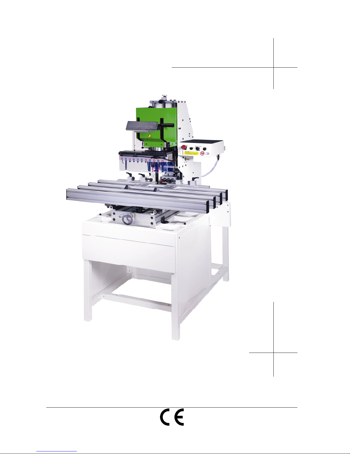
multiflex
OPERATING INSTRUCTIONS
technoplus Verarbeitungstechnik GmbH As of: 12.12.2007
6923 Lauterach / AUSTRIA Version:
1.0
Retain for future reference!
Page 2

2 Version 1.0
Page 3

Version 1.0
3
Identification data
Identification data manufacturer
technoplus Verarbeitungstechnik GmbH
Lerchenauerstraße 69
6923 Lauterach / AUSTRIA
Telephone: +43 (0) 5574 76178-0
Fax: +43 (0) 5574 76178-2
Email: [email protected]
Internet: www.technoplus.eu
Identification data marketing company
Grass GmbH
Grass Platz 1
6973 Höchst / AUSTRIA
Telephone: +43 (0) 5578 701-0
Fax: +43 (0) 5578 701-59
Email: [email protected]
Internet: www.grass.at
Identification data product
Product: Drilling and inserting machine
Type : multiflex
Item number: 80280
Serial number: …………
Year of manufacture: …………
Legal information relating to operating instructions
These operating instructions and the information contained therein have been compiled
with all due care and attention. However, technoplus Verarbeitungstechnik GmbH
accepts no liability for printing errors, other forms of error, or any damage resulting from
such.
technoplus Verarbeitungstechnik GmbH reserves the right to undertake changes to
their products which serve to facilitate their technical advancement. Such amendments
may not necessarily be documented individually in each case.
The copyright to these documents remains the sole property of the manufacturer. All
manner of reproduction, including excerpts, is only permitted with the permission of the
manufacturer. The only exception to this is where the copying of instructions is required
for the operation of the product.
© Copyright technoplus Verarbeitungstechnik GmbH 2007. All rights reserved.
Page 4

4 Version 1.0
Table of Contents
1.
General user information 6
1.1. Purpose of the document ................................................................................... 6
1.2. Positional information in the documentation....................................................... 6
1.3. Figures used ...................................................................................................... 7
1.4. Symbols used..................................................................................................... 8
2.
Basic safety instructions 9
2.1. General safety instructions................................................................................. 9
2.2. Obligations of the operating company.............................................................. 10
2.3. Obligations of the personnel ............................................................................ 10
2.4. Proper use ....................................................................................................... 10
2.5. Reasonably foreseeable misuse ...................................................................... 10
2.6. Safety equipment ............................................................................................. 11
2.7. Personal protective equipment......................................................................... 11
2.8. Hazards and safety measures ......................................................................... 12
2.9. Residual risk according to EN ISO 12100 parts 1+2 ........................................ 13
3.
Product information 14
3.1. Overview of machine with component descriptions.......................................... 14
3.2. Technical Data ................................................................................................. 15
3.3. Machine identification....................................................................................... 17
4.
Permissible tools 18
4.1. Vertical boring mill............................................................................................ 18
4.2. Horizontal boring mill........................................................................................ 18
5.
Permissible workpieces 19
5.1. Permissible materials ....................................................................................... 19
5.2. Permissible workpiece dimensions .................................................................. 19
6.
Unpacking and scope of delivery 20
6.1. Unpacking ........................................................................................................ 20
6.2. Scope of delivery.............................................................................................. 20
7.
Transport, Storage and Erection 21
7.1. Transport and storage conditions..................................................................... 21
7.2. Space requirements and ambient conditions ................................................... 21
7.3. Requirements for the foundations .................................................................... 21
7.4. Erection at final site.......................................................................................... 22
8.
Installation and commissioning 23
8.1. Pneumatic connection...................................................................................... 23
8.2. Electrical connection ........................................................................................ 23
8.3. Dust extraction connection............................................................................... 23
Page 5

Version 1.0
5
9.
Working with the machine 24
9.1. Clamping the drill bit into the quick-change chuck........................................... 24
9.2. Mounting the quick-change chuck on the boring head .................................... 24
9.3. Attaching a table extension.............................................................................. 25
9.4. Mounting the insertion matrices on the insertion frame ................................... 25
10. Settings on the machine 26
10.1. Setting the vertical bore depth ......................................................................... 26
10.2. Setting the vertical bore spacing...................................................................... 26
10.3. Setting the horizontal bore depth..................................................................... 27
10.4. Setting the horizontal bore height .................................................................... 27
10.5. Adjust the drilling speed................................................................................... 28
11. Troubleshooting and fault recovery 29
12. Maintenance 30
12.1. Maintenance schedule..................................................................................... 30
12.2. Cleaning instructions ....................................................................................... 31
13. Circuit diagrams 32
13.1. Pneumatic Diagram ......................................................................................... 32
13.2. Pneumatic components ................................................................................... 33
13.3. Electrical circuit diagram.................................................................................. 34
13.4. Electrical components...................................................................................... 35
14. Decommissioning and disposal 36
14.1. Decommissioning ............................................................................................ 36
14.2. Disposal........................................................................................................... 36
15. Warranty conditions 37
16. Miscellaneous 39
16.1. Declaration of conformity ................................................................................. 39
16.2. Resale sheet.................................................................................................... 41
16.3. Questionnaire 1 - Reason for purchasing the multifflex ................................... 43
16.4. Questionnaire 2 - Satisfaction.......................................................................... 45
17. Personal notes 47
Page 6
GENERAL USER INFORMATION
Version 1.0 6
1. General user information
1.1. Purpose of the document
These operating instructions serve to describe the operational processes and
maintenance of the machine as well as to provide important information required for
the safe and efficient handling of the machine.
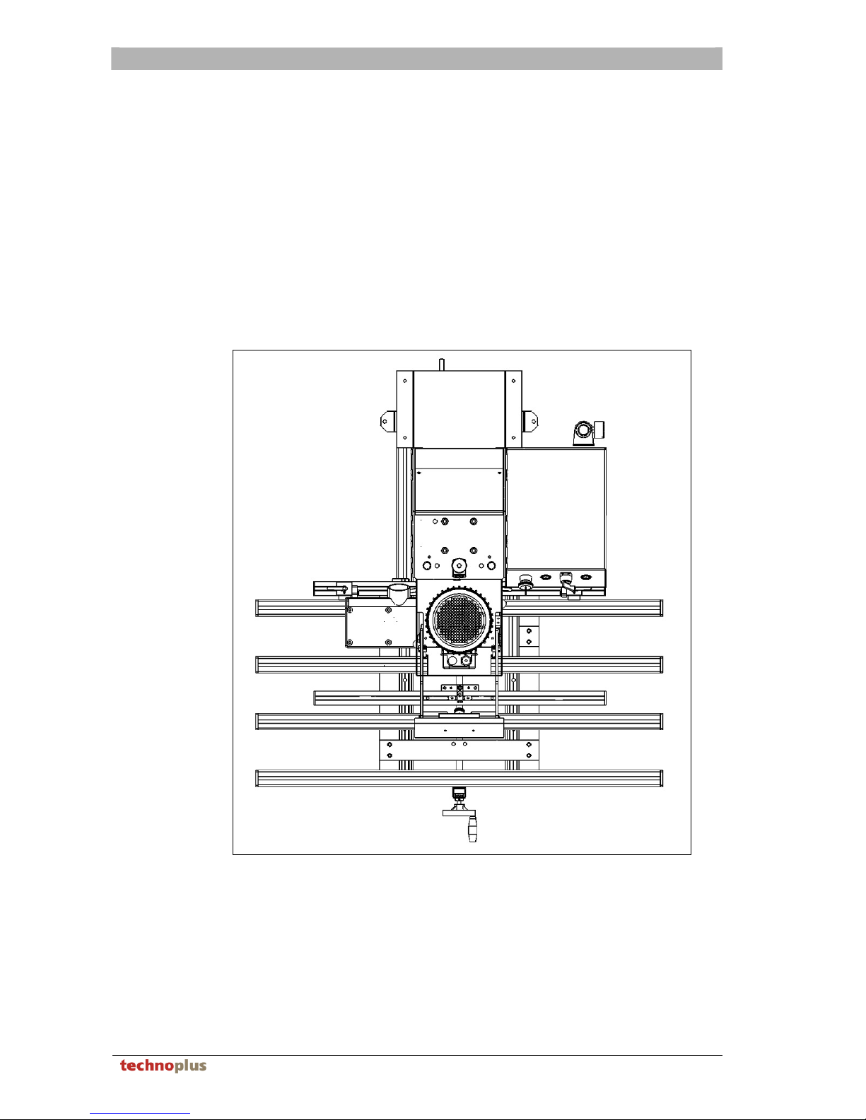
1.2. Positional information in the documentation
All directional and positional information in these operating instructions relate to the
operating position of the user.
Rear side of the machine
L
e
f
t
R
i
g
h
t
Front side of the machine
Operating position of the user
Page 7

GENERAL USER INFORMATION
Version 1.0 7
1.3. Figures used
Instructions and system reactions
Operating steps that are to be undertaken by operating personnel are depicted as
numbered lists. The order of the steps is to be maintained. The reactions to the
respective operations are marked by means of an arrow. Example:
1. Operation 1
Reaction to operation 1
2. Operation 2
Reaction to operation 2
Lists
Lists that do not have a set order are depicted as lists with dashes. Example:
– Dash 1
– Dash 2
Numbering in figures
Numbering in figures is shown within quotation marks. Example:
”1“
”2“
Page 8
GENERAL USER INFORMATION
8 Version 1.0
1.4. Symbols used
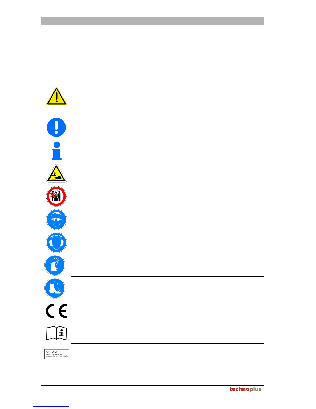
Important!
The symbols serve the purposes of safety and may not be removed or damaged
under any circumstances. Observe all warning and safety signs attached to the
machine.
Danger!
Immediate impending danger which will lead to serious injury
or death.
Warning!
Possibly dangerous situation which could lead to serious injury
or death.
Caution!
Possibly dangerous situation which could lead to minor injury.
Also warning of property damage.
Important!
Potentially damaging situation which could cause either the
product or property in its vicinity to be damaged.
Note!
For operational information and other useful information. Not to
be used for dangerous or potentially damaging situations.
Warning signs
Risk of injury due to crushing the hands and fingers.
Prohibition signs
The machine may only be operated by one person.
Mandatory signs
Wear eye protection
Mandatory signs
Wear ear protection
Mandatory signs
Wear protective gloves
Mandatory signs
Wear protective shoes
CE marks
Designates conformity with the valid EU directives which are
applicable to the product and which prescribe a CE
identification.
Note!
Observe the operating instructions
Note!
Note regarding lowering the drilling unit even with the motor
switched off
Page 9

BASIC SAFETY INSTRUCTIONS
Version 1.0 9
2. Basic safety instructions
2.1. General safety instructions
– The deployment and application of the drilling and inserting machine may only be
undertaken as described in these operating instructions.
– The operating company of the drilling and inserting machine is responsible for
maintenance of application-related national and international health, work and
safety regulations. In addition, the operating company is obliged to ensure that all
operating personnel have been trained in the operation of the machine.
– Work on the electrical equipment may only be undertaken by authorised specialist
electricians.
– Protect yourself from electric shocks.
– The pneumatic and electrical connection lines are to be laid in an orderly fashion
and are to be protected against damage (e.g. inside cable ducts).
– Before beginning each working day, all safety equipment is to be checked for
completeness and function.
– Only replace damaged parts with original replacement parts!
– The machine is always to be separated from the electrical mains as well as from the
pneumatic compressed air supply for all maintenance, repair and adjustment tasks.
– The electrical master switch must always be set to 0 and the EMERGENCY STOP
button pressed after completion of work, before changing tools, when changing
gears, or for all work in the area of the tools.
– It is to be secured against re-starting by unauthorised persons.
– The permissible tools are described in chapter 4. For your own safety, only use
tools of correspond strength from the manufacturer's supply portfolio.
– Particular care is to be taken with large workpieces which project over the edges of
the machine table. It is necessary to mount a larger rest (accessories - table
extension) or to use additional supports for the workpieces.
– Shavings may not be blown-off, rather, they are to be extracted by means of
suitable equipment.
– Always keep the working area and the machine clean, untidiness and obstructed
working areas increase the risk of injury.
– Only use the machine in clean rooms, do not leave the machine outdoors,
especially never leave it outside in the rain.
– Wear tight-fitting working clothes when working with the machine and use a hairnet
if you have long hair. In addition, the personal protection equipment is to be adhered
to and worn, see chapter 2.7.
– These operating instructions must be available to the operating personnel at all
times.
– Modifications and amendments as well as interfering with the electrical systems of
the drilling and inserting machine can lead to serious injury and are forbidden.
– The machine must always be shut-down immediately in the event of danger by
means of pressing the EMERGENCY STOP button.
– The machine may only be operated by one person.
– It is only permitted to operate the machine when standing in an upright position.
– Machine parts may not be used as props for the body.
– It is not permitted to reach into the running machine. When working, ensure that the
hands are kept out of the working range of the tools and the inserting frame.
Page 10
BASIC SAFETY INSTRUCTIONS
10 Version 1.0
2.2. Obligations of the operating company
The operating company is obliged to allow only those persons to work on the machine
who:
– are familiar with the basic regulations relating to working safety and accident
prevention,
– have been trained to work with the machine,
– have read these operating instructions and have signed them to confirm that they
have been understood.
The requirements of the EC directive for the usage of tools 89/655/EEC is to be
maintained.
2.3. Obligations of the personnel
Before beginning work, all persons who have been commissioned to work with the
machine are obliged to:
– observe the basic regulations relating to working safety and accident prevention,
– read the safety chapter and the warning information contained in these operating
instructions and to sign to confirm that they have been understood.
Please contact the manufacturer in the event of unresolved queries.
2.4. Proper use
Warning!
The machine is to be used solely in accordance with its proper use and is only to
be operated when in technically perfect working order!
The drilling and inserting machine is intended exclusively for drilling in solid wood or
wood-like materials (wood-based composite materials) and the inserting of fittings.
Only those tools may be used that are expressly detailed in chapter 4 may be used.
– Proper use also includes the following:
– the observance of the operating instructions and safety instructions
– the undertaking of cleaning and maintenance tasks.
2.5. Reasonably foreseeable misuse
Warning!
Dangerous situations can arise in the event of misuse!
All applications that are not specified under "proper use" or applications which exceed
these shall be considered as improper use!
The operator is responsible
– for any damage resulting from such,
– and the manufacturer accepts no liability.
The following misuse is not permissible:
– Drilling and inserting with materials which are not in accordance with the regulations
– Drilling and inserting of workpieces which are not in accordance with the regulations
– Simultaneous usage of the machine by more than one person.
Page 11

BASIC SAFETY INSTRUCTIONS
Version 1.0 11
2.5.1. Modifications or amendments
Unauthorised modifications or amendments to the machine shall void all manufacturer
liability and guarantee!
For this reason, do not make changes or additions to the machine without first seeking
the agreement and written permission of the manufacturer.
2.5.2. Replacement and wearing parts as well as auxiliary materials
The use of replacement and wearing parts from third-party manufacturers can be
dangerous. Only use original parts or parts that have been released for use by the
manufacturer. The manufacturer accepts no liability for damage caused by the usage
of replacement and wearing parts that have not been released by the manufacturer.
2.6. Safety equipment
Important!
Safety equipment, warning signs, etc., serve the purposes of safety and may not
be removed or damaged or deactivated under any circumstances.
– Lockable electrical master switch to secure against unauthorised starting and to
switch the machine off when setting up and adjusting.
– Lockable pneumatic EMERGENCY STOP switch to secure against unauthorised
starting and to switch the machine off when setting up and adjusting.
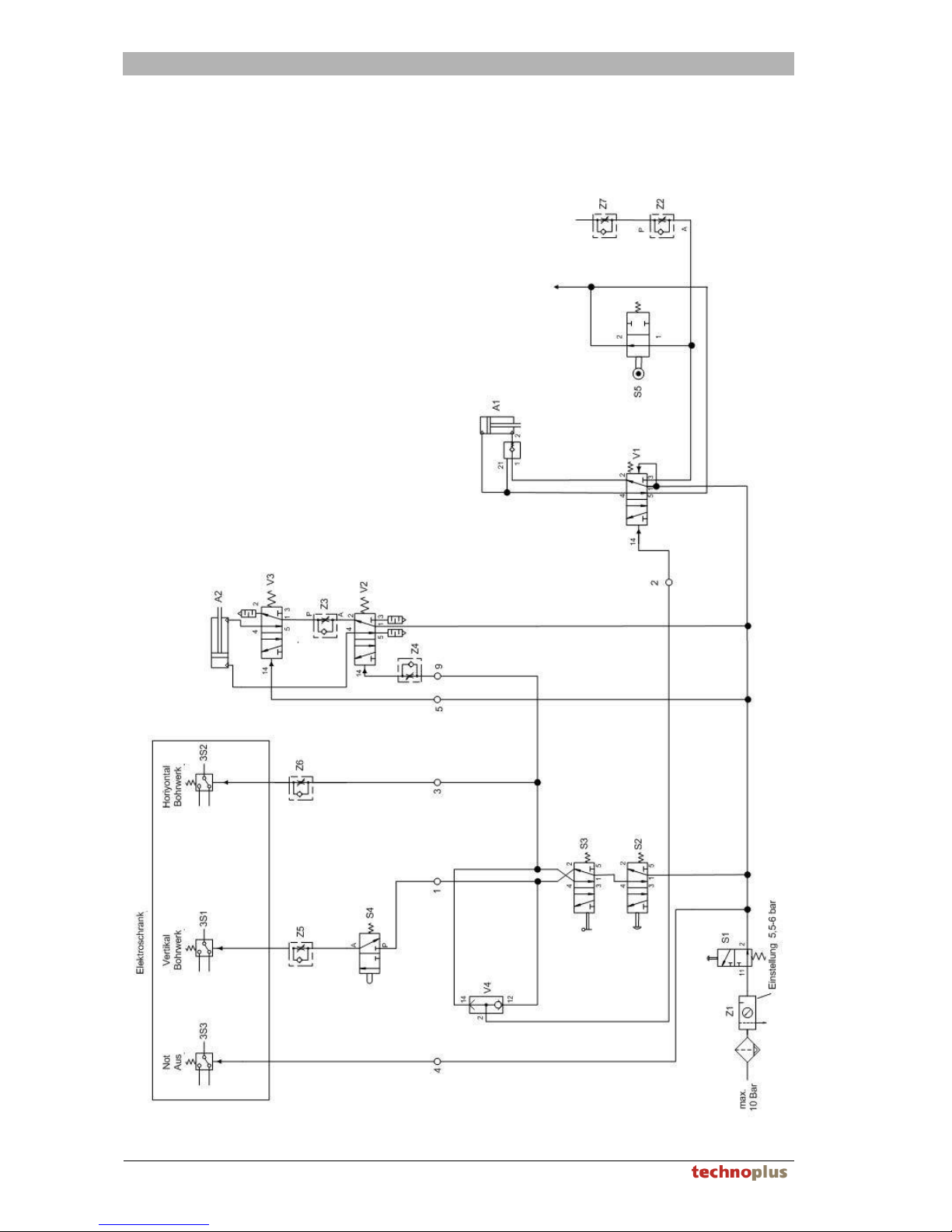
– Compressed air filter pressure-reducing-valve to prevent mechanical overloading of
the machine, see Pneumatic diagram chapter 13.1
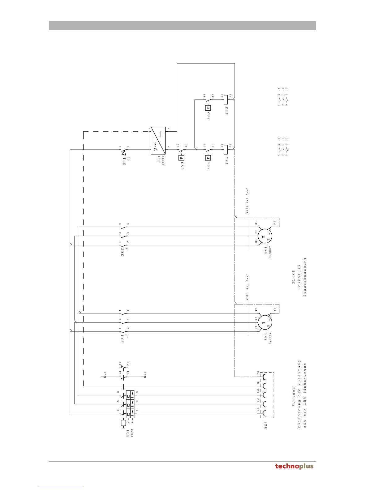
– Thermal overload protection for the electromotor, see Electrical circuit diagram
chapter 13.3
– Controllable back-pressure valve, directly on the master cylinder prevents the
machine from lowering in the event of pressure loss, the valve is only opened when
the start button is pressed, see Pneumatic diagram chapter 13.1
– Motors only run when the start button is pressed. After the start button has been
released, the motors start up after a delay. The delay duration can be adjusted in
the electrical switching cabinet.
– The motor does not run during the insertion process.
– Integrated dust extraction system to protect the operating personnel from fine
particulate matter.
– Various protective covers to protect against contact with the drill
2.7. Personal protective equipment
The operator must provide the following protective equipment.
Wear protective gloves
Wear protective shoes
Wear eye protection
Wear ear protection
Page 12

BASIC SAFETY INSTRUCTIONS
12 Version 1.0
2.8. Hazards and safety measures
Hazards and adverse effects can occur during the application of the machine,
– which can represent a risk to life and limb for the user or third-parties,
– for the machine itself, or
– to other property and ancillary materials.
In this case, the manufacturer accepts no liability.
The basis for safe handling and fault-free operation of this machine is the knowledge
of the safety and operating instructions contained within this documentation.
Hazard Safety measure
Release tool Chuck with clamping screw
Tool - breakage
only branded products from the manufacturer's
supply portfolio. The personal protection equipment
have to be worn
Tool - contact
All tools behind a transparent cover
Tool - machine contact
Safety drilling depth stop
Workpiece ejection
Workpiece stops
Advance mechanism No automatic advancing movements
Workpiece clamping
mechanism
Icon on hold-down device (= insertion frame)
Risk of impact Non-existent due to slow lifting motion
Drives
Direct drive in completely closed transmission
housing
Tool unit
Advance for lifting movement via buttons with collar
and without latching; maintenance of safety
margins according to EN 294 in relation to risk
Control, unexpected tool start
Control, unexpected lift
activation
Electrical control with PE converter, button with
collar and without latching
Control, tool-start during
insertion
Query of insertion frame with pneumatic valve
Electricity
Equipment according to EN 60204 part 1, VDE
0100 and IEC 384
Noise The personal protection equipment have to be worn
Dust Dust extraction system
Page 13

BASIC SAFETY INSTRUCTIONS
Version 1.0 13
2.9. Residual risk according to EN ISO 12100 parts 1+2
Important!
The machine has been built according to the current state-of-the-art and
recognised safety-relevant regulations.
However, danger to life and limb for the user or third-parties or adverse effects
to the machine or other property can occur during its operation.
Residual risks comprise:
– Caution, even when the electrical master switch is turned off, the machine will
move in the event that the start button is pressed, insofar as it is supplied with
compressed air.
– In the event of operation by unqualified personnel
– In the event of operation without the required safety and protective equipment
– in the event of improper tooling or improper tool attachment
– In the event of processing large workpieces without additional workpiece supports
– In the event of drilling, insertion or clamping movements of machine parts for the
2nd hand of the operating personnel
– In the event of additional persons in the working area
– In the event of interfering with the machine if it has not been properly secured
– In the event of failure to observe the regulations for proper use
– In the event of control system failure
Page 14
PRODUCT INFORMATION
14 Version 1.0
3. Product information
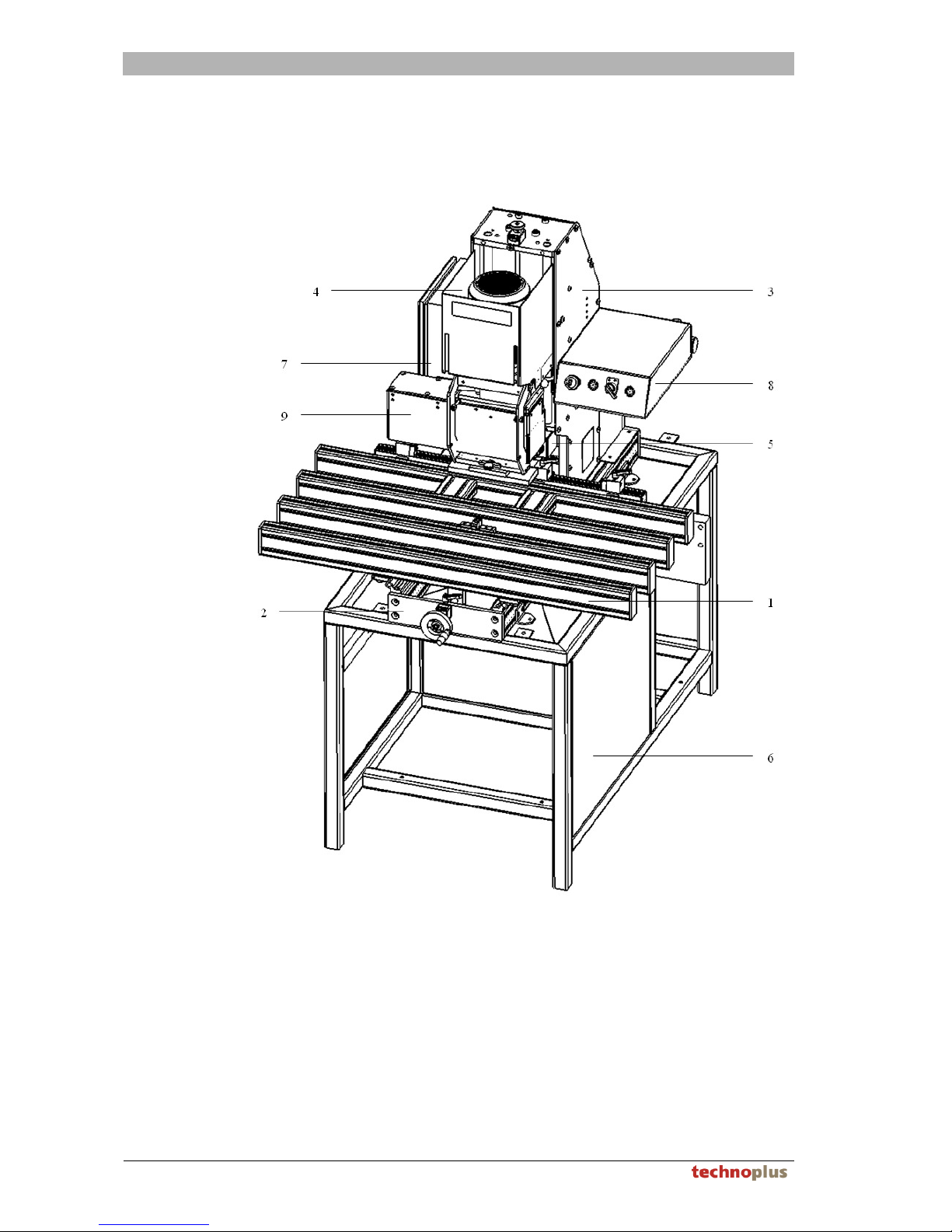
3.1. Overview of machine with component descriptions
”1“ Machine table
”2“ Base frames with guidance columns for horizontal movement
”3“ Base frames with guidance columns for vertical movement
”4“ Vertical boring mill
”5“ Horizontal boring mill
”6“ Machine foundation (=accessory)
”7“ Electrical switching cabinet
”8“ Pneumatic console
”9“ Vertical boring transmission
Page 15

PRODUCT INFORMATION
Version 1.0 15
3.2. Technical Data
Main dimensions of the machine
Machine table width
1,000 mm
Machine table depth at 20mm boring gap
500 mm
Machine table height with foundation (=accessory)
950 mm
Machine table height without foundation
200 mm
Machine table overall height with foundation
1,650 mm
Machine table overall height without foundation
910 mm
Machine overall depth
1,010 mm
Setting ranges for the machine
Vertical boring mill
Drill lengths - maximum possible length
57 mm
Drill diameter - maximum permissible drill diameter at pot spindle
35 mm
Drill diameter - maximum permissible drill diameter on all other
spindles
15 mm
Bore row - greatest possible spacing
200 mm
Bore row - smallest possible spacing
0 mm
Furniture hinges - greatest possible pot spacing (central boring)
50 mm
Furniture hinges - smallest possible pot spacing (central boring)
9 mm
Horizontal boring mill
Drill lengths - maximum possible length
150 mm
Drill bit diameter - maximum permissible drill bit diameter
16 mm
Boring height - maximum possible boring height
5 mm
Boring height - minimum possible boring height 40 mm
Bore depth - maximum bore depth
Approx. 120 mm
Overall weight of the machine
Overall weight of the machine vertical / horizontal 14/03 with foundation
Approx. 220 kg
Overall weight of the machine vertical / horizontal 14/03 without
foundation
Approx. 160 kg
Ambient conditions
Temperature in operation
+10 to +30 °C
Temperature in storage
-10 to +40 °C
Humidity in operation or storage, not condensation!
10 to 80 %
Page 16

PRODUCT INFORMATION
16 Version 1.0
Electrical connection
Supply voltage according to type plate
..... V
Frequency according to type plate
….. Hz
Installed load for 3-phase motors
1.8 kW
Rating of the supply is to correspond with local regulations, however, minimum 1.5mm²
fused supply with max. 1.5x nominal current according to type plate, max. 10 A.
H07RN-F5G1.5 or equivalent
Pneumatic connection
Dust, water and oil-free compressed air
min. 5.5 bar
Max. working pressure
max. 6 bar
Max. permissible pressure in supply line
max. 10 bar
Compressed air consumption per bore stroke 6 bar
Approx. 1.2 l
Compressed air consumption per bore stroke, suction performance for compressor
Approx. 7.5 l
Pressing force at 0.6 MPa (6bar)
Approx. 3,000 N
Dust extraction connection
The machine must be connected to an extraction system in accordance with the
interface description. The connection lines are to be designed to be flame-resistant. If it
is necessary to connect the machine to the extraction plant electrically, the
manufacture offers a volumetric flow rate monitor as optional equipment, which can be
connected to the interface shown on the electrical circuit diagram, chapter 4-007.
The dust and shavings collection elements of the machine are to be designed in such
a way as that the value remains safely below the technical guideline concentration limit
value for wood dust. (Connection to a plant according to the interface description, test
protocols by an independent institution available).
Thread diameter for dust extraction vertical bore head Ø 80 mm
Thread diameter for dust extraction horizontal bore head Ø 80 mm
Thread diameter for dust extraction machine foundation Ø 80 mm
Required extraction performance per connection Approx. 360 m³/h
Mean air speed 20 m/sec
Static negative pressure vertical bore head 1500 Pa
Static negative pressure horizontal bore head 500 Pa
Static negative pressure machine foundation 500 Pa
Page 17

PRODUCT INFORMATION
Version 1.0 17
Noise emission values
According to DIN EN ISO 11202 supplemented by CEN -TC 142, the
workplace emission value LpA amounts to:
idle running .......... dB(A)
Working noise 84.5 dB(A)
According to EN ISO 3746 supplemented by CEN -TC 142, the
sound power level L
WA
amounts to:
Idle running ...........dB(A)
Working noise 94.7 dB(A)
The measurement uncertainty constant K amounts to 4 dB(A).
The following supplements specified by CEN - TC142 in order to achieve an accuracy
class better than 3 dB were taken into consideration:
– The environmental corrective factors K
2A
and K3A amount to ≤ 4 dB.
– The difference between the foreign noise sound pressure level and the noise sound
pressure level at all measuring points is ≥ 6 dB.
– K3A is calculated according to appendix A, DIN EN ISO 11204.
– A rectangular enveloping measurement surface with 9 measuring points of
1.0 m from the reference surface is used.
Under consideration of ISO 7960 sections 0 to 4, the machine-specific conditions of
measurement were as follows:
Drill bit: 1x concealed hinge drill bit d=35mm; t=13mm n=2750 min-1
2x dowel drill bits d= 8mm; t=13mm n=2750 min-1
Workpiece: Uncoated chipboard
Microphone position: 1m distance form the centre of the bore axis at a height of 1.5m.
Note
The values given here are emission values and may not simultaneously represent safe
working area values. As there is no correlation between emission values and working
area values, these cannot be reliably used in order to determine whether or not
additional precautions are required. Factors which could affect the current working
area values include the duration of the influence, the characteristics of the working
space, other sources of noise, the number of machines and other neighbouring
influences. The reliable working area values can also vary from one country to another.
However, this information should enable the operator to make a better estimation of
the potential hazards and risks.
3.3. Machine identification
The machine is equipped with a type plate which details the following:
– machine type
– machine number
– year of manufacture
– weight
– the required compressed air.
Page 18

PERMISSIBLE TOOLS
18 Version 1.0
4. Permissible tools
Warning!
Hazards for both the machine and its users can occur in the event that
impermissible tools are used!
The operator is responsible
– for any damage resulting from such,
– and the manufacturer accepts no liability.
4.1. Vertical boring mill
Only commercially-available hard metal or HSS drill bits may be used with dimensions
as given in the following table. We recommend only using tools of correspond
strength from the manufacturer's supply portfolio.
– Body diameter
max. 10 mm
– Overall length of the drill bit
max. 57 mm
– Drill bit diameter drive spindle
max. Ø 35 mm
– Drill bit diameter residual spindles
max. Ø 16 mm
4.2. Horizontal boring mill
Only commercially-available hard metal or HSS drill bits may be used with dimensions
as given in the following table. We recommend only using tools of correspond
strength from the manufacturer's supply portfolio.
– Body diameter
max. 10 mm
– Overall length of the drill bit
max. 100 mm
– Drill bit diameter drive spindle
max. Ø 19 mm
– Drill bit diameter residual spindles
max. Ø 16 mm
Page 19

PERMISSIBLE WORKPIECES
Version 1.0 19
5. Permissible workpieces
Warning!
Hazards for both the machine and its users can occur in the event that
impermissible workpieces are used!
The operator is responsible
– for any damage resulting from such,
– and the manufacturer accepts no liability.
5.1. Permissible materials
Only workpieces made from
– wood (solid wood) or
– wood-like materials (wood-based composite materials) may be processed.
Other materials may not be processed.
5.2. Permissible workpiece dimensions
The workpieces must be laid stably and securely on the machine table, without the
need for the operator to hold onto the workpieces in order to prevent them from falling
down. This unconstrained positioning (without being held by the user) is a requirement
for the safe operation of the machine and must be ensured by means of the user.
– The maximum workpiece thickness is 40 mm.
– If the workpieces are larger than 300 x 300 mm, then they must be positioned on
bolsters placed next to the machine such as supports or similar devices.
The manufacturer offers table and guide extensions as optional accessories for this
purpose.
Page 20

UNPACKING AND SCOPE OF DELIVERY
20 Version 1.0
6. Unpacking and scope of delivery
6.1. Unpacking
When unpacking the drilling and inserting machine, the paperboard packaging should
be removed in the upward direction. The machine body is protected against corrosion
by means of sprayed oil.
The sprayed oil can be left on the machine in order to protect against corrosion.
After unpacking, the machine is to be checked for possible damage. Damage is to be
reported immediately to the haulage company and the supplier, both by telephone and
in writing.
6.2. Scope of delivery
The scope of delivery, especially the optional equipment, must be checked against the
delivery notes for completeness immediately after unpacking.
Any incorrect parts are to be reported to the supplier immediately.
The basic equipment comprises:
– 14 Spindle gear drive with chuck (without drill bit)
– Insertion frame to mount the insertion matrices
– 2 Connections for dust extraction system
– 2 mounted lifting eye bolts in order to be able to lift the machine.
– Operating tools
– Operating Instructions
Page 21
TRANSPORT, STORAGE AND ERECTION
Version 1.0 21
7. Transport, Storage and Erection
7.1. Transport and storage conditions
Warning!
There is a risk of tipping and crushing when transporting the machine!
The transport personnel must wear suitable protective shoes.
– The machine is supplied fully assembled and ready for operation, mounted on an
IPPC special pallet, and protected by means of paperboard packaging.
– The machine may only be lifted and transported by means of suitable lifting gear
(e.g. a fork lift truck) under the pallet. If this is not adhered to, serious transport
damage can ensue.
– Protect the packaged machine during transportation and avoid storage in damp or
wet areas. Storage temperature from -10 ºC to +40 ºC.
7.2. Space requirements and ambient conditions
The required space depends on the size of the workpieces to be processed.
– The minimum depth amounts to approx. 180 cm.
– The minimum width depends on the amount of extension guides.
– For individual parts for tall cupboards with heights of 240 cm, a space requirement
of approx. 5 m width needs to be allowed for.
– The lighting in the working area must be designed in accordance with workplace
regulations.
7.3. Requirements for the foundations
Warning!
These requirements must be adhered to, otherwise there is a risk of the
machine tipping.
The foundation must be stable, secure from tilting, and free from vibration. The
manufacturer recommends using its optional foundation accessory. However, a
workbench can be used, insofar as it fulfils the following requirements. It is not
permitted to operate the machine without fixed anchorage.
– Load bearing capacity minimum 250 kg.
– Foundation width minimum 400 mm.
– Foundation height = desired work table height - 200 mm
(e.g.: 950 mm - 200 mm = 750 mm)
– Foundation depth minimum 700 mm; the machine may project over the foundation
max. 200 mm at the front and max. 250 mm to the rear.
Page 22
TRANSPORT, STORAGE AND ERECTION
22 Version 1.0
7.4. Erection at final site
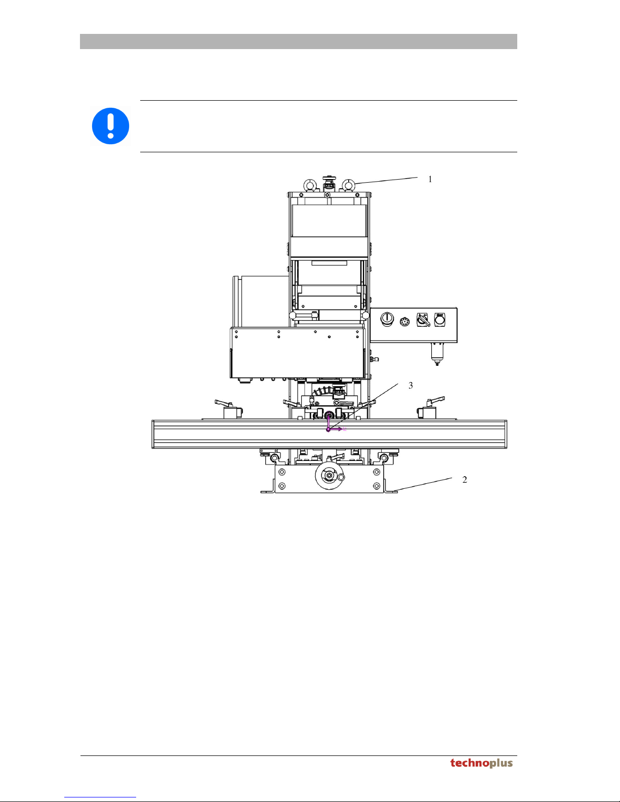
Important!
The machine may not be lifted up by the machine table (aluminium frame), as
this could cause the machine settings to be misadjusted.
Only lift the machine by the lifting eye bolts "1", observe centre of gravity "3"!
3. Lift the machine up by the lifting eye bolts "1" and position it on a suitable
foundation, see chapter 7.3
4. Screw the machine to a stable, non-tilting and vibration-free foundation by means
of the four brackets "2".
It is not permitted to operate the machine without fixed anchorage.
Page 23
INSTALLATION AND COMMISSIONING
Version 1.0 23
8. Installation and commissioning
8.1. Pneumatic connection
Warning!
When the machine is connected to a pneumatic source, the motor cradle of the
vertical boring mill with transmission can move upwards and the horizontal
boring mill can move backwards in the machine frame.
The machine is equipped with a 2 m long air hose from factory. Depending on the
country of destination, a European quick-release hose coupling is fitted.
1. Establish the compressed air connection, max. 10 bar, via a quick-release hose
coupling or a cut-off cock with vent at a distance of max. 2 m (it must be possible
for the operating personnel to isolate the machine from the compressed air supply
at any time).
2. The manometer on the maintenance unit is preset by the manufacturer to min. 5.5
– max. 6 bar (0.55 - 0.6 MPa) and may not be changed.
3. Undertake a functional test with the master switch turned off and without quickchange chuck. When pressing the start button, the motor cradle must move
downwards, when the button is released, the machine must immediately return to
the initial position.
8.2. Electrical connection
Danger!
The electrical connection for the machine may only be undertaken by means of
authorised specialist personnel according to the regulations of the respective
country.
The machine must be isolated from the electrical mains before undertaking
maintenance tasks on the machine's electrical systems.
The machine is equipped with a 3 m long, 5-pin connection cable from factory.
Depending on the country of destination, a connector plug (CEE 5 x 16 A) is fitted.
H07RN-F5G1.5 or equivalent
After successful pneumatic commissioning and after successful connection to the
mains,
1. turn the master switch on.
2. Swing the insertion frame all the way up,
3. without inserting a drill bit, press the start button
Vertical boring mill moves downwards and the motor switches on.
4. Release the start button
Machine returns to the initial position. Determine the direction of rotation
though the ventilation grille when the motor is running down. The direction of
rotation must match the marking arrow on the motor housing!
5. A change to the direction of rotation may only be undertaken by a specialist!
8.3. Dust extraction connection
Important!
The machine may "NOT" be operated without a dust extraction system!
The connection lines are to be designed to be flame-resistant and must be earthed.
The extraction system can be changed by means of a current transformer.
Page 24
WORKING WITH THE MACHINE
24 Version 1.0
9. Working with the machine
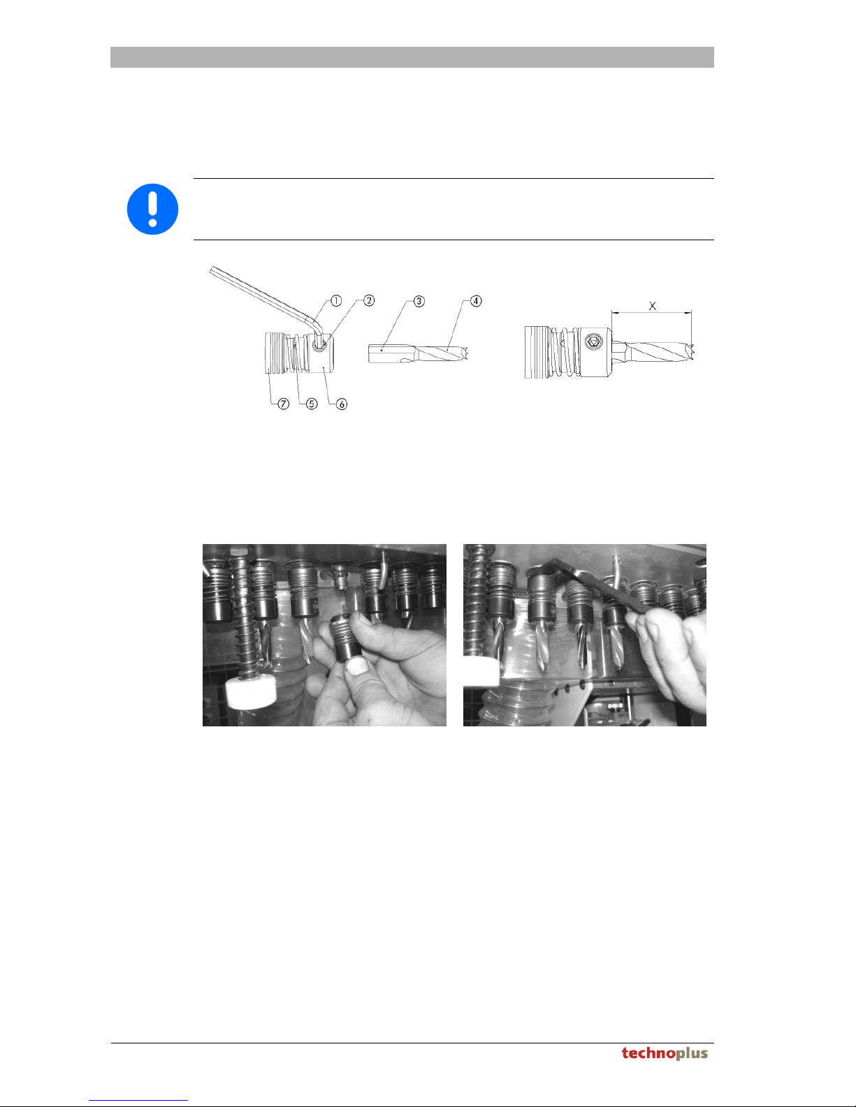
9.1. Clamping the drill bit into the quick-change chuck
Important!
In order that all drill bits reach the same depth, it is necessary that all drill bits
are set to the same gauge "x".
1. Release the fastening screw "2" with the 4 mm hexagon key "1"
2. Insert a drill bit "4" into the chuck "5" up to the stop pin, observe the position of the
area "3"
3. Tighten the fastening screw "2"
9.2. Mounting the quick-change chuck on the boring head
1. Pick up a quick-change chuck with drill bit in one hand
2. Guide the quick-change chuck with drill bit up to a free head spindle
3. Slide the clamp collar with the other hand in the direction of the drill bit,
4. position the quick-change chuck with drill bit onto the spindle
5. Release the clamp collar and turn the quick-change chuck by approx. a 1/2 turn,
until the clamp collar returns to the initial position
6. When dismantling a quick-change chuck with drill bit, pull the clamp collar in the
direction of the drill bit and pull the quick-change chuck with drill bit away from the
spindle.
Page 25
WORKING WITH THE MACHINE
Version 1.0 25
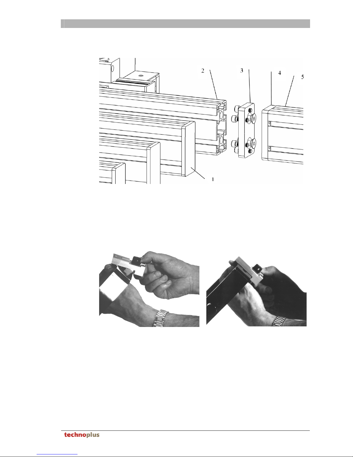
9.3. Attaching a table extension
1. Remove end cap "1"
2. Screw the connection plate "3" to the table profile "2" (2 screws)
3. Screw the connection plate "3" to connection plate "4". (6 screws)
Ensure that table profile "2" and extension profile "5" are level before tightening up
the screws.
9.4. Mounting the insertion matrices on the insertion frame
1. Swing the insertion frame upwards
2. Release the clamping screw on the insertion matrix
3. Hook the matrix in, with the clamping screw first
4. Tighten up the clamping screw by hand
Page 26
SETTINGS ON THE MACHINE
26 Version 1.0
10. Settings on the machine
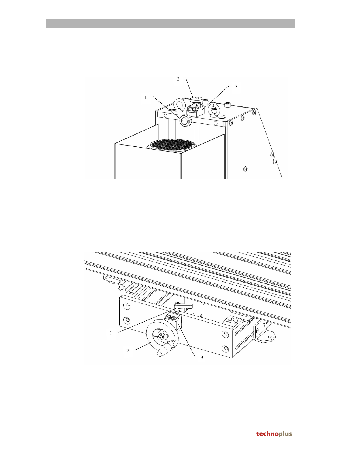
10.1. Setting the vertical bore depth
The actual bore depth is not adjusted, rather, the thickness of the workpiece to be
processed. The display is adjusted in such a way as that 57mm long drill bits provide
a bore depth of 13 mm.
1. Release star knob "1"
2. Turn thumbscrew "2" until the counter "3" shows the thickness of the material to
be processed.
3. Clamp star knob "1"
10.2. Setting the vertical bore spacing
1. Release clamping lever "1"
2. Turn hand wheel "2" until the counter "3" shows the desired position. When
adjusting the bore spacing, one should always adjust from a greater value to a
smaller value, in order to allow play for play compensation in the threaded spindle.
3. Clamp clamping lever "1"
Page 27
SETTINGS ON THE MACHINE
Version 1.0 27
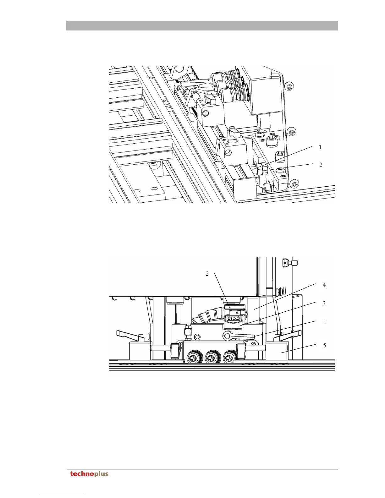
10.3. Setting the horizontal bore depth
The horizontal boring mill has a drill depth stop screw "1"
Setting the bore depth is undertaken by means of interdependently tightening both
hexagon nuts "2".
10.4. Setting the horizontal bore height
1. Press the EMERGENCY STOP button
2. Release side guides "5" and slide them so that the
3. rule insert can be removed (insofar as one was used)
4. Pull the horizontal boring mill forwards by the column "4"
5. Release the clamping lever "1" by turning it anticlockwise
6. Adjust the thumbscrew "2" until the desired size is shown on the counter "3".
7. Clamp the clamping lever "1" by turning it clockwise
8. Press the horizontal boring mill backwards by hand
9. release the EMERGENCY STOP button
Page 28
SETTINGS ON THE MACHINE
28 Version 1.0
10.5. Adjust the drilling speed
Note!
The per hard workpiece, the smaller the operating speed!
The better the tool, the more largely the operating speed!
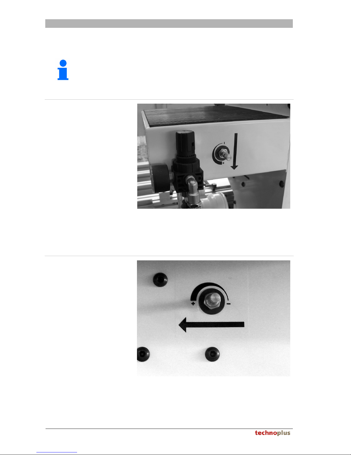
Adjust the drilling speed vertically
The vertical production machine works with a increased, not adjustable setting speed
and a steplessly adjustable working speed.
The vertical operating speed could be controlled by adjusting the throttle.
A rotation in the clockwise direction decreases the operating speed.
Adjust the drilling speed horizontal
The horizontal production machine works with only a steplessly adjustable speed.
Setting speed = operating speed.
The vertical operating speed could be controlled by adjusting the throttle.
A rotation in the clockwise direction decreases the operating speed.
Page 29

TROUBLESHOOTING AND FAULT RECOVERY
Version 1.0 29
11. Troubleshooting and fault recovery
The following overview provides information about faults, their causes and remedies.
In the event that a fault cannot be rectified despite using the table, please contact your
supplier.
No. Fault Possible causes / Remedy
Compressed air attach, adjust manometer gauge to 6
bar.
1. Machine fails to move
Release the EMERGENCY STOP button
Swing the insertion frame all the way up
2. Motor fails to start
Turn on the main switch
3.
Motor turns, the tool
doesn’t.
Clutch defectively, contact manufacturers
Controll the motor direction of rotation, only by means
of specialists
Exchange blunt tools
4.
Tool fails to drill
properly
Tighten the locking lever at the drilling head
Too little compressed air available, adjust manometer
gauge to 6 bar.
5.
Fitting is not cleanly
pressed in
correct the right insertion position
6.
Stroke too fast/slowly Pneummatics throttle close/open
Page 30
MAINTENANCE
30 Version 1.0
12. Maintenance
Note!
Professional maintenance facilitates a trouble-free and efficient production flow.
Some of the detailed tasks are highly dependent on the level of use and ambient
conditions. Different maintenance cycles may be required in individual cases.
12.1. Maintenance schedule
Important!
Maintenance work may only be carried out if the machine has been
correspondingly secured. This means:
The master switch on the electrical switching cabinet must be positioned to 0
and the machine must be isolated from the compressed air supply.
After receiving suitable training, the operating personnel can undertake these tasks
autonomously in accordance with the following table and the intervals given.
Interval Description / task
Daily or
always
before use
Check of all safety equipment for function and completeness.
Clean machine of coarse shavings. No not use compressed air for
this, rather, use a suitable extraction system.
Daily or
always after
use
Secure the machine against unauthorised usage (padlock)
Weekly, or
as required
Drain filter pressure-reducing-valve, to do so, isolate machine from
compressed air supply (semi-automatic draining) (see chapter 12.1.1)
Clean guide columns and lightly grease with commercially-available
grease.
Check the settings display by means of a test bore
Functional check of side guides, clean if necessary.
Monthly
Positional check of the insertion matrices
Annually
The multiflex has proven its durability in several fatigue tests.
However, in order to ensure many years of optional functionality, it is
recommended to have the machine serviced by an experienced
customer services engineer every 1 - 3 years, depending on duration
of use.
Page 31
MAINTENANCE
Version 1.0 31
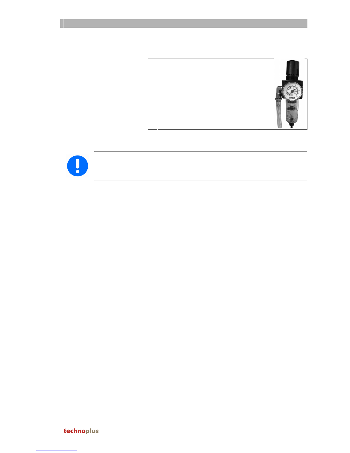
12.1.1. Drain condensate in pneumatic maintenance unit
1
Place a container under the
maintenance unit.
2
Open the drainage screw for the
condensate.
3
Allow the entire condensate to drain off
and dispose of it in an environmentallycompatible manner.
4
Close the condensate drain screw
again.
12.2. Cleaning instructions
Important!
Cleaning work may only be carried out if the machine has been correspondingly
secured. This means:
The EMERGENCY STOP button must have been pressed.
– Clean the machine as required: Vacuum up the shavings, clean with a soft, dry
cloth, do not use aggressive cleaning agents such as solvents, thinners, benzene
or similar.
– Grease the non-painted surfaces from time to time with a lightly oiled cloth. Only
use non-acidic oil.
Page 32
CIRCUIT DIAGRAMS
32 Version 1.0
13. Circuit diagrams
13.1. Pneumatic Diagram
Page 33
CIRCUIT DIAGRAMS
Version 1.0 33
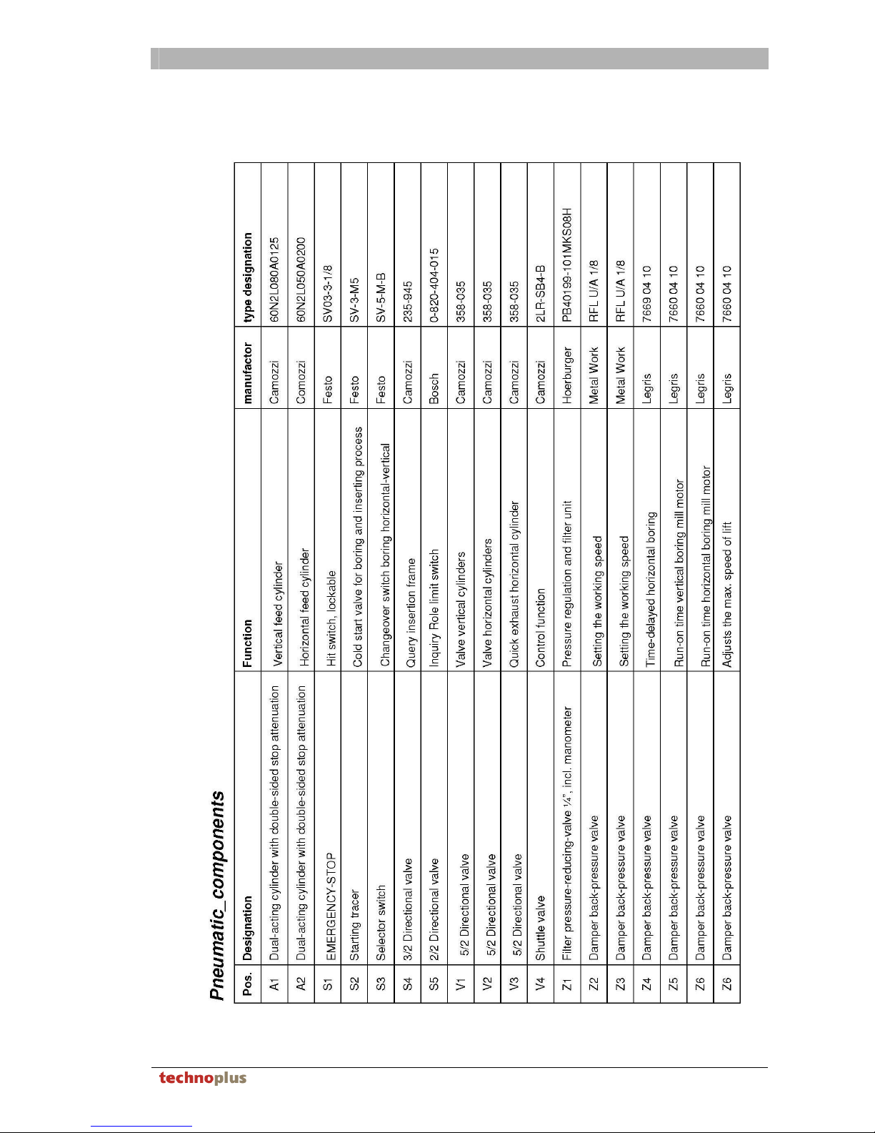
13.2. Pneumatic components
Page 34
CIRCUIT DIAGRAMS
34 Version 1.0
13.3. Electrical circuit diagram
Page 35
CIRCUIT DIAGRAMS
Version 1.0 35
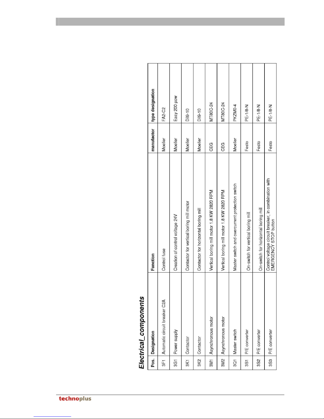
13.4. Electrical components
Page 36

DECOMMISSIONING AND DISPOSAL
36 Version 1.0
14. Decommissioning and disposal
14.1. Decommissioning
Important!
After every temporary decommissioning, a new commissioning process must
be carried out.
1. Isolate machine from compressed air supply
2. Isolate machine from electrical mains
3. Secure the machine against unauthorised usage (padlock)
4. Undertake maintenance and cleaning on machine
14.2. Disposal
Important!
All parts, auxiliary materials and operating fluids from the machine should be
separated according to type and disposed of according to local regulations and
directives.
The machine comprises, among other things, of the following materials:
Steel / iron parts:
– Workpiece guides
– Support plates
– Fixing elements
– …
Aluminium:
– Basic frame profiles
– Support plates
– Parts of the pneumatic cylinder
– …
Various plastics:
– Hold-down device
– Pneumatic components
– …
The following parts cannot be assigned to any material group:
– Clamp rollers
– Pneumatic components
– …
Page 37

WARRANTY CONDITIONS
Version 1.0 37
15. Warranty conditions
We provide a warranty for the supplied product within the framework of the "General
terms of delivery of the machine and constructional steelworks trade association of
Austria, item 11, Warrantee".
All warrantee claims shall be void in the event of improper use, repair by means of
unauthorised persons, in the event of the application of third-party replacement parts,
as well as in the event of third-party accessory usage without the written permission of
the manufacturer.
We reserve the right to undertake technical and cosmetic changes for any purpose.
The machine corresponds to the state-of-the-art and all appropriate regulations at the
time of shipping from the manufacturer's factory. The manufacturer is not obliged to
retrofit previously supplied machines to fulfil subsequently amended regulations freeof-charge.
In the event of a warrantee claim, please contact your authorised dealer quoting the
machine type and machine number.
The guarantee or warrantee covers exclusively the replacement or repair of faulty
components.
The following is not covered by the warrantee:
– Transport damage, as such claims must be lodged immediately with the postal
service, rail operator or haulage company.
– Normal wear and tear or wearing parts, e.g. tools
– Damage caused by failure to observe the safety regulations
– Damage caused by improper handling or due to improper use of the machine
– Damage to workpieces being processed
– Compensation for downtime
– Loss of earnings due to faulty machines
– Assembly time, travel time, travel costs
Page 38

WARRANTY CONDITIONS
38 Version 1.0
Page 39
MISCELLANEOUS
Version 1.0 39
16. Miscellaneous
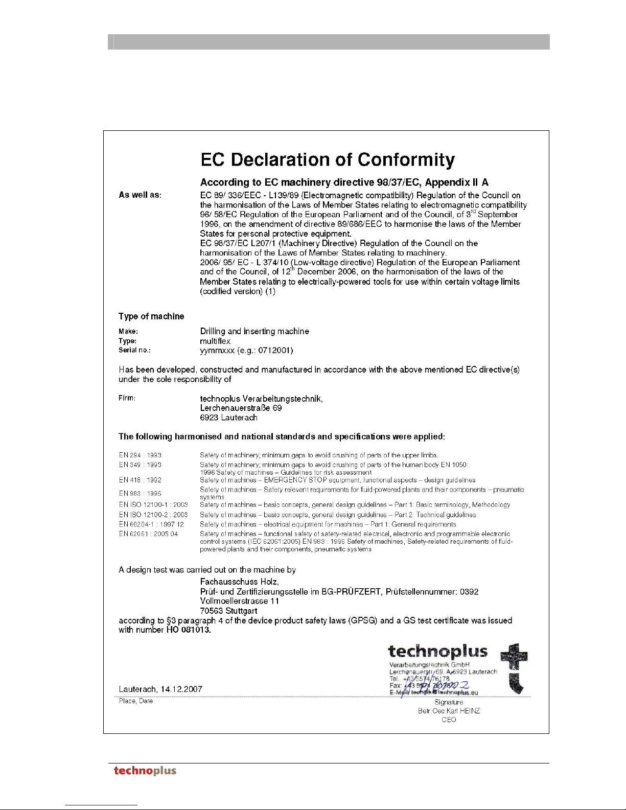
16.1. Declaration of conformity
Page 40

MISCELLANEOUS
40 Version 1.0
Page 41

MISCELLANEOUS
Version 1.0 41
16.2. Resale sheet
Sales person:
Name:……………………………………………………………………………………………..
Street:…………………………………………………………………………………………….
Postcode:………………………………….. City:……………………………………………
Country:…………………………………….
Telephone:………………………………. Fax:………….……………………………….
Machine:
Type: ……………………………………….. Machine number:…………………………
Date of sale:………………………………………………………………………………….
Reason why multiflex was sold:
…………………………………………………………………………………………………….
…………………………………………………………………………………………………….
…………………………………………………………………………………………………….
…………………………………………………………………………………………………….
…………………………………………………………………………………………………….
…………………………………………………………………………………………………….
…………………………………………………………………………………………………….
…………………………………………………………………………………………………….
…………………………………………………………………………………………………….
…………………………………………………………………………………………………….
…………………………………………………………………………………………………….
…………………………………………………………………………………………………….
…………………………………………………………………………………………………….
…………………………………………………………………………………………………….
…………………………………………………………………………………………………….
…………………………………………………………………………………………………….
…………………………………………………………………………………………………….
Buyer:
Name:……………………………………………………………………………………………..
Street:…………………………………………………………………………………………….
Postcode:………………………………….. City:……………………………………………
Country:…………………………………….
Telephone:…………………………………. Fax:………….……………………………….
After resale of the machine, please send fully completed resale sheet back to the
manufacturer. The buyer agrees that his data may be stored in an electronic database.
Page 42

MISCELLANEOUS
42 Version 1.0
TO:
technoplus
Verarbeitungstechnik GmbH
Lerchenauerstraße 69
6923 Lauterach
AUSTRIA
Notes:
…………………………………………………………………………………………………….
…………………………………………………………………………………………………….
…………………………………………………………………………………………………….
…………………………………………………………………………………………………….
…………………………………………………………………………………………………….
…………………………………………………………………………………………………….
…………………………………………………………………………………………………….
…………………………………………………………………………………………………….
…………………………………………………………………………………………………….
…………………………………………………………………………………………………….
…………………………………………………………………………………………………….
…………………………………………………………………………………………………….
…………………………………………………………………………………………………….
…………………………………………………………………………………………………….
…………………………………………………………………………………………………….
…………………………………………………………………………………………………….
…………………………………………………………………………………………………….
…………………………………………………………………………………………………….
…………………………………………………………………………………………………….
…………………………………………………………………………………………………….
…………………………………………………………………………………………………….
…………………………………………………………………………………………………….
…………………………………………………………………………………………………….
…………………………………………………………………………………………………….
…………………………………………………………………………………………………….
…………………………………………………………………………………………………….
Sender:
…………………………………………………
…………………………………………………
…………………………………………………
…………………………………………………
…………………………………………………
…………………………………………………
Page 43

MISCELLANEOUS
Version 1.0 43
16.3. Questionnaire 1 - Reason for purchasing the multifflex
Buyer:
Name:……………………………………………………………………………………………..
Street:…………………………………………………………………………………………….
Postcode:………………………………….. City:……………………………………………
Country:…………………………………….
Telephone:……………………………..…. Fax:………….……………………………….
Size of company:................persons
Machine:
Type: ……………………………………….. Machine number:…………………………
Operational use of the machine Approx. ………….…hours per month
Application of multiflex in area (please check where applicable):
_Kitchen furniture manufacture _General interior work
_General furniture manufacture _.................………………………………….
Application purpose of machine (please check where applicable):
_ Boring hinges _ Inserting hinges
_ Boring dowel base plates _ Inserting dowel base plates
_ Boring connecting fittings _ Inserting connecting fittings
_ Boring modular base plates _ Boring rows of holes
_ Boring fronts for drawer rails _ Boring back walls for drawer rails
_ Handle bore holes in fronts
_.................................................................
For what reason did you choose multiflex instead of a machine from a competitor?
(Please check where applicable)
_ Price _ Appearance (optically)
_ Variety of application options _ Quality (design of the machine)
_ Extensive accessories
_ Price-performance trade off
_ Because you were convinced by Grass _ Stability of the machine
_ Because you are a Grass processor
_.................................................................
How did you hear about multiflex? (Please check where applicable)
_ Advertisement in a paper _ Visit by a sales representative
_ Dealer showroom
_................................................... ..............
_ Visit to a trade show
_................................................... ..............
After purchase of the machine, please send fully completed questionnaire back to the
manufacturer. The buyer agrees that his data may be stored in an electronic database.
Page 44

MISCELLANEOUS
44 Version 1.0
TO:
technoplus
Verarbeitungstechnik GmbH
Lerchenauerstraße 69
6923 Lauterach
AUSTRIA
Notes:
…………………………………………………………………………………………………….
…………………………………………………………………………………………………….
…………………………………………………………………………………………………….
…………………………………………………………………………………………………….
…………………………………………………………………………………………………….
…………………………………………………………………………………………………….
…………………………………………………………………………………………………….
…………………………………………………………………………………………………….
…………………………………………………………………………………………………….
…………………………………………………………………………………………………….
…………………………………………………………………………………………………….
…………………………………………………………………………………………………….
…………………………………………………………………………………………………….
…………………………………………………………………………………………………….
…………………………………………………………………………………………………….
…………………………………………………………………………………………………….
…………………………………………………………………………………………………….
…………………………………………………………………………………………………….
…………………………………………………………………………………………………….
…………………………………………………………………………………………………….
…………………………………………………………………………………………………….
…………………………………………………………………………………………………….
…………………………………………………………………………………………………….
…………………………………………………………………………………………………….
…………………………………………………………………………………………………….
…………………………………………………………………………………………………….
Sender:
…………………………………………………
…………………………………………………
…………………………………………………
…………………………………………………
…………………………………………………
…………………………………………………
Page 45

MISCELLANEOUS
Version 1.0 45
16.4. Questionnaire 2 - Satisfaction
Buyer:
Name:……………………………………………………………………………………………..
Street:…………………………………………………………………………………………….
Postcode:…………………………………... City:……………………………………………
Country:……………………………………..
Telephone:…………………………………. Fax:………….……………………………….
Machine:
Type: ……………………………………………………………………………………………..
Machine number:……………………………………………… ……………………………
Current / frequency according to type
plate:………………………………………………............
How satisfied are you with multiflex? (Please check where applicable):
_Very satisfied _Moderately
_Good _Not at all
Would you buy a multiflex again? (Please check where applicable or supplement):
_ yes _ no
Because the machine meets (does not meet) my requirements
_ yes _ no
Due to price / performance
_ yes _ no
Due to the economic situation
_ yes _ no
Due to the customer service...................................................................
_ yes _ no
...................................................................................................................
_ yes _ no
...................................................................................................................
_ yes _ no
...................................................................................................................
_ yes _ no
...................................................................................................................
What would you change on the multiflex?
…………………………………………………………………………………………………….
…………………………………………………………………………………………………….
…………………………………………………………………………………………………….
…………………………………………………………………………………………………….
…………………………………………………………………………………………………….
…………………………………………………………………………………………………….
…………………………………………………………………………………………………….
One month after purchase of the machine, please send fully completed questionnaire
back to the manufacturer. This will help us to better accommodate your customer
requirements. The buyer agrees that his data may be stored in an electronic database.
Page 46

MISCELLANEOUS
46 Version 1.0
TO:
technoplus
Verarbeitungstechnik GmbH
Lerchenauerstraße 69
6923 Lauterach
AUSTRIA
Notes:
…………………………………………………………………………………………………….
…………………………………………………………………………………………………….
…………………………………………………………………………………………………….
…………………………………………………………………………………………………….
…………………………………………………………………………………………………….
…………………………………………………………………………………………………….
…………………………………………………………………………………………………….
…………………………………………………………………………………………………….
…………………………………………………………………………………………………….
…………………………………………………………………………………………………….
…………………………………………………………………………………………………….
…………………………………………………………………………………………………….
…………………………………………………………………………………………………….
…………………………………………………………………………………………………….
…………………………………………………………………………………………………….
…………………………………………………………………………………………………….
…………………………………………………………………………………………………….
…………………………………………………………………………………………………….
…………………………………………………………………………………………………….
…………………………………………………………………………………………………….
…………………………………………………………………………………………………….
…………………………………………………………………………………………………….
…………………………………………………………………………………………………….
…………………………………………………………………………………………………….
…………………………………………………………………………………………………….
…………………………………………………………………………………………………….
Sender:
…………………………………………………
…………………………………………………
…………………………………………………
…………………………………………………
…………………………………………………
…………………………………………………
Page 47

PERSONAL NOTES
Version 1.0 47
17. Personal notes
…………………………………………………………………………………………………….
…………………………………………………………………………………………………….
…………………………………………………………………………………………………….
…………………………………………………………………………………………………….
…………………………………………………………………………………………………….
…………………………………………………………………………………………………….
…………………………………………………………………………………………………….
…………………………………………………………………………………………………….
…………………………………………………………………………………………………….
…………………………………………………………………………………………………….
…………………………………………………………………………………………………….
…………………………………………………………………………………………………….
…………………………………………………………………………………………………….
…………………………………………………………………………………………………….
…………………………………………………………………………………………………….
…………………………………………………………………………………………………….
…………………………………………………………………………………………………….
…………………………………………………………………………………………………….
…………………………………………………………………………………………………….
…………………………………………………………………………………………………….
…………………………………………………………………………………………………….
…………………………………………………………………………………………………….
…………………………………………………………………………………………………….
…………………………………………………………………………………………………….
…………………………………………………………………………………………………….
…………………………………………………………………………………………………….
…………………………………………………………………………………………………….
…………………………………………………………………………………………………….
…………………………………………………………………………………………………….
…………………………………………………………………………………………………….
…………………………………………………………………………………………………….
…………………………………………………………………………………………………….
…………………………………………………………………………………………………….
…………………………………………………………………………………………………….
…………………………………………………………………………………………………….
…………………………………………………………………………………………………….
…………………………………………………………………………………………………….
…………………………………………………………………………………………………….
…………………………………………………………………………………………………….
…………………………………………………………………………………………………….
…………………………………………………………………………………………………….
…………………………………………………………………………………………………….
Page 48

technoplus
Verarbeitungstechnik GmbH
Lerchenauerstraße 69
6923 Lauterach / AUSTRIA
t: +43 (0)5574 76178
f: +43 (0)5574 76178-2
m:
www.technoplus.eu
Art. Nr. 80454 – Version 1.0 – 12/2007
 Loading...