

Page 1
Techno-Matic A/S
Granlidevej 22, Hornum
DK-9600 Aars
Denmark
Tel: +45 96987711
Fax: +45 98661822
www.techno-matic.dk
START
STOP
Mode: Running
>Temperature 65.0 C
O2 8.0%
Setting
o
TM3006 Technical Manual
Revision: 7.95rev.3
TABLE OF CONTENTS
Table of Contents .............................................................................................................................................. 1
Important notes..................................................................................................................................................2
1
Transient Protection.............................................................................................................................. 2
2
Power Current Connections ................................................................................................................. 2
3
Sensor Connections..............................................................................................................................2
4
The Print ............................................................................................................................................... 3
5
Connecting the TM3006 ....................................................................................................................... 4
Page 2

TM3006 TECHNICAL MANUAL
© Techno-Matic A/S Side 2
Important notes
This documentation has been made solely to serve as an aid to the stoker producer to describe his
product. Techno-Matic A/S does not issue any warranty that this documentation fulfils or satisfies
the national or international demands for documenting the product since this is the duty of the
individual stoker producer. However, Techno-Matic A/S will be thankful for any comment or advice
that may help to improve this manual.
Please note: You must always turn off the power supply before actually touching anything in the
system in order to avoid dangerous situations. Only persons with permission from the stoker
producer and with an authorization in accordance with the national legislation must carry out any
interventions/repairs in the installations.
1 TRANSIENT PROTECTION
In order to secure the controller against interference, relays and solenoid valves should be transient
protected. (DC relays and solenoid valves with diodes and AC relays and solenoid valves with RC filter).
2 POWER CURRENT CONNECTIONS
IMPORTANT:
Always prefuse the system with maximum 10A prefuses.
Always make sure not to exceed the maximum limit of the total load on the outputs.
Unused cable glands must be filled out and all cable glands must be tighten with an open ring wrench.
The main supply cords must not exceed 1,5 mm2
Supply
Terminal Main supply N
L3
L2
L1
Supply for system 230VAC (L1) or 400VAC. Remember ALWAYS
to connect N.
Maximum prefuse 10A
Power Current Output
Maximum total load on all outputs 2000W
Terminal Stoker N
U
V
W
Connecting the Stoker Motor 230VAC (U) Maximum load 550W
Or
400VAC. Maximum load 3*550W
Terminal Blower N
U
Connecting the Blower Motor 230VAC. Maximum load 550W
Terminal N
Ignition /Motor 2 U
Connecting the Ignition Unit/
Motor 2
230VAC. Maximum load 550W
3 SENSOR CONNECTIONS
Digital Inputs
Terminals 1 & 11 Function input On/off switch
Terminals 2 & 12 Function input On/off switch
Terminals 3 & 13 Function input On/off switch
Terminals 4 & 14 Hot boiler Thermostat
Analogue Inputs
Terminals 5 & 15 Boiler Temperature Sensor
NTC thermistor (12kOhm at 25 °C)
Terminals 6 & 16 Stoker Tube Temperature Sensor
NTC thermistor (12kOhm at 25 °C)
Terminals 7 & 17 Photo Sensor
Exhaust Gas Temperature Sensor
Danfoss LDS
PT1000 (6 mW)
Terminals 8 & 18 Oxygen Sensor Lambda probe
Supply oxygen
sensor
Terminals 9 & 19 Oxygen Sensor Heating Element 12VAC for Heating Element
. Please Note: During
the heating of the oxygen sensor, the supply for the
computer will be gone for about 3 minutes!
Photo Sensor
Terminals K & A Photo Sensor Transmitter K = 0V. DC. A = 5 V. DC.
Alarm Output
Terminals k1 & k2 Alarm Output Potential free output: Max. 1A.
Max. 30 V. DC.
Page 3
TM3006 TECHNICAL MANUAL
© Techno-Matic A/S Side 3
4 THE PRINT
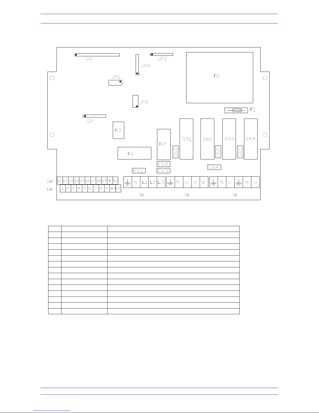
Besides the terminals at the bottom of the print there are the following components/sockets:
F1 Fuse 63mA Fuse on primary side of transformer
JP1 10-pol socket Program Updating Connection
JP2 10-pol socket RS232 Connection
JP3 4-pol socket Optional connector (Not in use)
JP4 4-pol socket Optional connector (Not in use)
J12 8-pol socket Keyboard (foil)
K1 Relay Hot Boiler Relay
K2 Relay Hot Boiler Relay
K3 Relay Alarm relay
SR1 Solid State Relay Stoker
SR2 Solid State Relay Stoker
SR3 Solid State Relay Blower
SR4 Solid State Relay Ignition/Motor 2
TR 230V/12V Transformer
U3 16-pol socket Display
Page 4
TM3006 TECHNICAL MANUAL
© Techno-Matic A/S Side 4
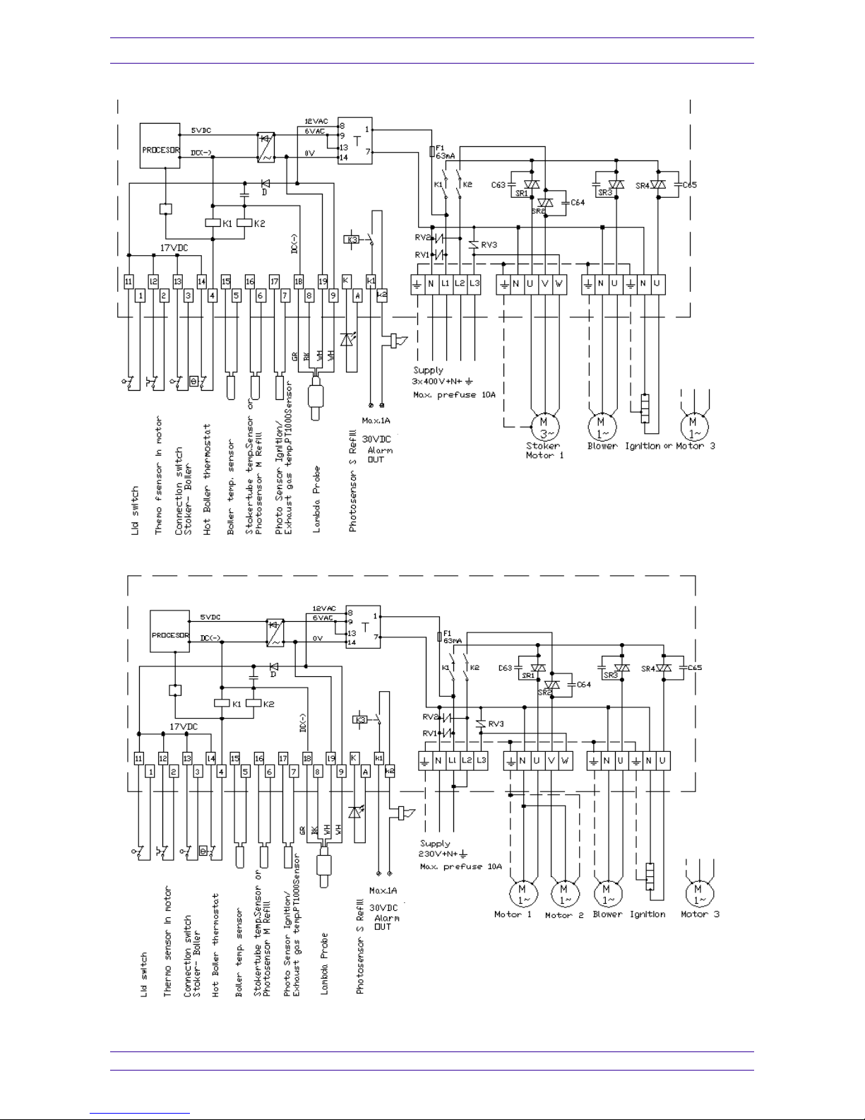
5 CONNECTING THE TM3006 BY 400 VAC
6 CONNECTING THE TM3006 BY 230 VAC
C62
C62
C62
 Loading...