

Page 1

Troubleshooting Guide
Problem Cause Solution
Strobe does not
start flashing
when you dial 911
or the
programmed
number or touch
the STROBE
ON/OFF button.
1. There is no power to
the transmitter.
2. The tra ns mi tte r is
not properly
connected to the
phone line.
3. More than 3 seconds
lapsed between
numbers while
initially
programming the
transmitter if using
the secondary
emer genc y n u mber.
4. The distance
between the
transmitter and
strobe is more than
30 meters (90’).
5. If an extra strobe
was used, it may not
have been properly
synchronized to the
transmitter.
1. Ensure the AC
power source is
working.
2. Ensure that the
phone cable is
plugged into the
transmitter and the
phone jack per the
instructions.
3. Reprogram the
transmitter us i ng
less than 3 seconds
between the digits
you n enter (if the
secondary
emer genc y n u mber
is being used).
4. Move the strobe
closer to the
transmitter.
5. Sy nchroni ze t he
extra strobe as per
the instruction.
(please see Page
7,8)
Strobe does not
turn off when you
dial #911, #the
programmed
number or touch
the STROBE
ON/OFF button.
1. The distance
between the
transmitter and
strobe is more than
30 meters
2. No power to the
strobe
3. Less than 8 seconds
lapsed since your
last activation.
1. Move the strobe
closer to the
transmitter.
2. Replace the
batteries in the
strobe.
3. Press the STROBE
ON/OFF button
until you hear a
beep
16
911 Alert Owner’s Instructions
What is the 911 Alert?
The 911 Alert lets police and ambulance services find you in
case of an emergency when seconds count. You can mount
your 911 guiding strobe on your window, door, and/or mailbox.
You can activate the 911 guiding strobe by:
1. Dialing 911 from your phone
2. Programming another emergency number and dialing it
3. Pressing the STROBE ON/OFF button on the
transmitter
The 911 Alert plugs into your telephone and senses when you
dial 911 or any emergency number from any extension.
Dialing 911 (or any other emergency number) triggers a radio
frequency (RF) signal that begins flashing the Strobe. You can
see the strobe from up to one mile away at night and up to 1/8
mile away during the day.
You can also use the 911 Alert as a convenience device
(delivery service, guests and so on) by pressing the STROBE
ON/OFF non-emergency button on the transmitter.
Each 911 model has its own user-specified signaling code.
This allows your unit to operate totally independently of any
other units in the neighborhood.
Page 2

1
Setting Up the Unit
Before you set up the unit, check that you have the following
items:
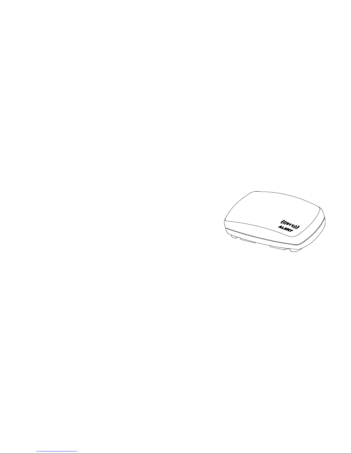
•
Transmitter
Button Description
STROBE
ON/OFF
Turns the strobe on/off
POWER Green indicates power is on
STROBE Red indicates strobe active (both emergency
or convenience modes)
911 DIALED Yellow indicates strobe has been activated
through the phone
2
911 Alert Parts List/Order Form
Quantity Part # Description Cost Total
RS-0011 Extra Receiver/ Strobe 30.00
PS-0020 AC / DC Power
Supply
10.00
TM-0030 Transmitter 30.00
MP-0050 Set Mounting parts 5.00
PC-0060 Phone Cable 5.00
AAA-4 Set 4 Energizer AAA’s 2.00
AA-6 Set 6 Energizer AAs 3.00
Shipping/Handling 7.95 7.95
Total
Payment Methods: Check, money order, credit card
Name ____________________________
Address __________________________
City, State Zip code
__________________________________
Visa /Mastercard Number _____________________________
Expiration date: __________________________________
Today’s date: _____________________________________
Phone (home & work) ______________________________
Page 3
Signature _________________________________________
15
C. Uncovered or non-warranted parts will, upon request, be
replaced per the replacement parts list, plus a $7.95
shipping
& handling charge for each shipment. The $7.95 and the
cost
of replacement parts must be included with the request for
replacement parts. If uncovered parts are requested with the
covered parts, only one $7.95 shipping & handling payment
is required.
D. The seller reserves the right to change the shipping &
handling charges and/or replacement parts prices without
notice.
WARRANTY DISCLAMERS
This warranty does not cover damage from intentional misuse,
abuse, fire, flood, or damage unrelated to the use of the product
for which such products are ordinarily intended. This warranty
is valid only on products purchased in and used in the United
States. The express warranties contained herein are in lieu of all
other warranties, expressed or implied, including but not
limited to the warranty of merchantability and fitness for a
particular purpose. The seller will not be liable for any
incidental or consequential damages, costs, or expenses
incurred by the purchaser.
LEGAL REMEDIES
This warranty gives you specific legal rights, but other rights
might be available pursuant to laws that vary from state to state.
14
•
Strobe (Receiver)
The strobe includes:
•
Multiple ultra bright LEDs;
•
Self-Testing Switch (Momentary Spring Switch)
•
6 AA alkaline batteries
•
Power AC/D C ada p t er
Input: 120VAC
Page 4

60 HZ
Output: 6VDC
100mA
3
•
Phone Cable
•
Mounting Brackets
for flush / mount
on door or wall
( 1 )
( 2 )
4
emergency signal from the transmitter. A special
integrated circuit (IC) chip both searches for this
signal, then rests to conserve battery life. This rest
period can take as long as 8 seconds. This search
and rest sequence extends battery life up to 8 times.
90 Day Limited Warranty
The seller warrants its 911 Alert to the original purchaser
against defects in material or workmanship for a period of 90
days from the date of purchase. During this period, the seller
will -- at its option -- repair or replace the defective part.
Covered parts include the power supply, strobe/receiver,
transmitter, and mounting parts.
WARRANT Y LIMIT ATI ON S, OBTAINI N G SER VICE AND
GENERAL INFORMATION
A. During the warranty period, covered parts will be repaired
or
replaced and shipped at no charge. Include $7.95 for
Page 5

shipping and handling for each return regardless of the
number of parts included.
B. To obtain warranty service, return the covered defective or
broken part(s) in a package that adequately protects the
part(s), a copy of proof of purchase, description of the
broken or defective parts, and $7.95 shipping & handling to
the seller.
13
Changing the Battery
The strobe constantly draws power while continuously
“searching” for a ‘911 signal’. You, therefore, should change
the batteries when the strobe appears dimmer, or every 6
months (whichever comes first).
To change the batteries:
1. Open the back of the battery cover on the Strobe/receiver
(see In st alling the Batte ry).
2. Remove the old batteries and properly discard them.
3. Install 6 AA batteries (Eveready Energizers are
recommended) correctly aligning them in the battery
compartment.
Important Notes on Operation
!!!!"
Do not operate the transmitter when it beeps quickly.
This indicates the system is sending the signal to the
Strobe/receiver. Wait until it beeps slowly.
!!!!
""""
When you use the 911 Alert system, there may be a
delay of up to 8 seconds before the strobe begins to
flash (or goes off). The receiver portion of the strobe
continually consumes power as it searches for an
12
Connecting the Transmitter
1. Open the battery cover on the rear of the transmitter and
install 4 AAA batteries (not included) for backup in case of
power failures.
The green power LED on the transmitter will light.
Battery Cover
Page 6

2. Unplug the cable from the telephone.
3. Plug this cable into the back of the 911 Alert connector
labeled LINE IN
5
4. Plug one end of the supplied phone cable into the connector
labeled TEL OUT.
5. Plug the other end into the wall telephone outlet from which
you unplugged the phone.
6. Plug the AC power supply into the 911Alert connector
labeled 6V.
7. Plug the AC end into a 110-115V outlet.
Programming a non-911
Emergency Number
The transmitter recognizes when someone dials ‘911’. If your
area does not use 911 as the emergency number, or you want to
use another number to activate the strobe, you can program a
different number (up to 11 digits).
To program an additional number:
1. Ensure that the transmitter is connected (see Connecting the
Transmitter above).
2. On your phone keypad (receiver on the hook), press “##”
twice.
3. Dial the emergency number you want to program, then
press “#” once.
!!!!
"
Do not exceed 3 seconds between numbers when
programming the number into the transmitter.
This additional number (or 911) now activates the strobe.
6
Testing the System
You can test the system without actually dialing 911 (or your
other programmed emergency number).
To test the system without calling 911, dial “ * ” before the
number.
For example,
1. Dial
*
911 or * programmed number
The Strobe will start flashing without the call going
through.
2. To turn the strobe off, dial
#
911
or
#
programmed
number
.
TEL OU T LIN E IN
6V
Cover Release
Page 7

!
If you had really dialed 911, # 911 also turns the
strobe off.
3. Try the
*
911
/
#
911
test on other phone extensions.
!"
When activating the strobe from the phone
(emergency use), the transmitter beeps and the “911
DIALED” light flashes slowly while the strobe is
flashing.
Using The 911 Alert in Non-Em ergency Mode
You can use the 911 Alert in the non-emergency mode. For
example, when waiting for a delivery or guests, just push the
large STROBE ON/OFF button on the transmitter. The Strobe
will flash until this button is pushed again.
!!!!
"
The unit may flash several times before turning off.
11
Door Mounting
To mount the strobe on the door:
1. Fix the #1 mounting bracket on the door using 2 screws.
2. Snap the strobe into # 1 Mounting Bracket
Mailbox Mounting
1. Fix the #2 Mounting bracket on the top of Mailbox
using 2 screws.
2. Snap the strobe’s clip into the #2 Mounting bracket.
3. Rotate the strobe to the forward position.
10
Before Using the System
Before you use the ‘911 Alert’, remove the plastic tab from the
battery com par tm ent.
This plastic tab prevents battery drain in shipment.
Remove the tab carefully, pull it out in the direction of the
arrow. If it tears, it will then be necessary to open the back to
remove the tab inside.
Page 8

Self-Testing Button
Test the separate Strobe. Press the self-testing button. The
strobe will flash. Release the button. It will stop flashing.
Adding Additional Strobes
You can use additional strobes with your system. To do this,
you must synchronize each additional strobe to the transmitter.
To synchronize a new strobe to the system:
Open the battery cover on the rear of transmitter. On
the back of the battery cover you will find a sticker which
shows the position of its coded switches.
7
Coded Switches -Sticker
Unscrew the four screws at the edge of the Strobe.
Remove the lens, you will see the coded switches. Adjust these
switches to match with those on the sticker of the transmitter.
Close both units. Test the new strobe by pushing the
Strobe ON/OFF button of the transmitter.
8
Installing and Mounting the Strobe
You can mount the strobe on a windowsill, door, or mailbox.
Install the strobe in a place that is clearly visible from the street.
Window Mounting
To mount the strobe on a window:
Pull out
Synchronizing
Switch
ON DIP
1 2 3 4 5 6 7 8
Page 9

1. Snap the strobe into the #2 mounting bracket.
2. Stick the #2 mounting brackets on the windows, using
2-sided foam tape.
3. Rotate the strobe until the strobe’s red lens faces
forward.
4. To mount on the windowsill, screw the base into the
sill.
9
SPECIAL NOTES-----Custom er Instructions
This equipment complies with Part 68 of the FCC rules. On the bottom
of this equipment is a label that contains, among other information, the FCC
certification number and ringer equivalence number (REN) for this
equipment. If requested, this information must be provided to the telephone
company.
An FCC compliant telephone cord and modular RJ11 plug is provided
with this equipment. This equipment is designed to be connected to the
telephone network or premises wiring using a compatible modular jack that
is part 68 compliant. See installation instructions for details.
The REN is used to determine the quantity of devices that may be
connected to the telephone line. Excessive RENs on the telephone line may
result in the devices not ringing in response to an incoming call. Typically,
the sum of RENs should not exceed five (5.0). To be certain of the number
of devices that may be connected to a line (as determined by the total
RENs) contact the local telephone company.
If the 911 Alert Dialing Sensor causes harm to the telephone network,
the telephone company will notify you in advance that temporary
discontinuance of service may be required. But if advance notice isn't
practical, the telephone company will notify the customer as soon as
possible. Also, you will be advised of your right to file a complaint with the
FCC if you believe it is necessary.
The telephone company may make changes to it's facilities, equipment,
operations or procedures that could affect the operation of the equipment. If
this happens the telephone company will provide advance notice so you can
make t he nec e ss a r y modifi c a ti o ns to maintai n uninterr up ted ser v i c e.
If trouble is experienced with this equipment 911 Alert Dialing Sensor,
for repair or warranty information, please contact:
Technology Programs Inc.
P.O. Box 172
Bradley, Il 60915
Telephone: 815-932-4890
If the equipment is causing harm to the telephone network, the
telephone company may request that you disconnect the equipment until the
problem is resolved.
You should not attempt to repair this equipment yourself. This
equipment contains no customer or user serviceable parts.
Connection to party line service is subject to state tariffs. (Contact the
state public Part 68 Application Guide 44 utility commission, public service
commission or corporation commission for information.)
Page 10

This device complies with part 15 of the FCC rules. Operation is
subject to the following two conditions: (1) This device may not cause
harmful interference, and (2) this device must accept any interference
received, including interference that may cause undesired operation.
Modifications or changes to the device not expressly approved by the
technology programs could void the user’s authority to operate the
equipment.
Mike Reeves – Quality Control Manager Date
 Loading...