

Page 1
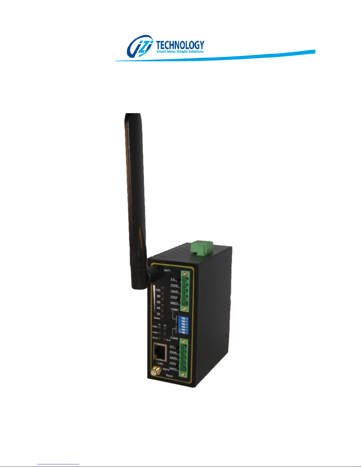
SPX5 – INDUSTRIAL GATEWAY
User Manual
Page 2

Contents Table
Product Capabilities. ........................................................................................................................... 2
Hardware Installation .......................................................................................................................... 3
Power Supply Connector ..................................................................................................................... 3
Serial Ports Connectors ....................................................................................................................... 4
Serial Ports Configuration Switches ................................................................................................ 4
Ethernet............................................................................................................................................... 5
Indicator Lights. ............................................................................................................................... 6
Reset Push Button ............................................................................................................................... 6
Setting up the SPX5 for the first time ................................................................................................. 8
Operation and Configuration of the SPX5 ......................................................................................... 10
Data Base ....................................................................................................................................... 11
Module Configuration. .................................................................................................................. 12
Gateway Name and Description ............................................................................................... 12
Gateway Security Configuration ............................................................................................... 12
Ethernet (LAN) and WiFi (WLAN) Configuration ........................................................................... 13
Network Protocols Configuration ..................................................................................................... 16
Modbus TCP/IP Client Protocol ..................................................................................................... 17
Modbus TCP/IP Server Protocol .................................................................................................... 19
EtherNet/IP Tag Client ................................................................................................................... 21
NTP Protocol.................................................................................................................................. 24
Serial Protocol Configuration ........................................................................................................ 25
Modbus RTU Master Configuration .............................................................................................. 25
User Programmable Scripts ............................................................................................................... 28
Examples of Useful Lua Scripts ...................................................................................................... 28
Actions at Constant Intervals .................................................................................................... 28
Read and Write of the SPX5 Database values ........................................................................... 28
Math Functions over Database Values...................................................................................... 29
Availabel Objects in the SPX5 Scripting Language ........................................................................ 30
WEB HMI ........................................................................................................................................... 30
Appendix. .......................................................................................................................................... 34
IZI Technology Inc, 3651 Pegasus Dr. Ste. 117 Bakersfield, CA 93308 USA.
Tel: (661) 412-3494 -- email: [email protected]
www.izitechnology.com
Page 3
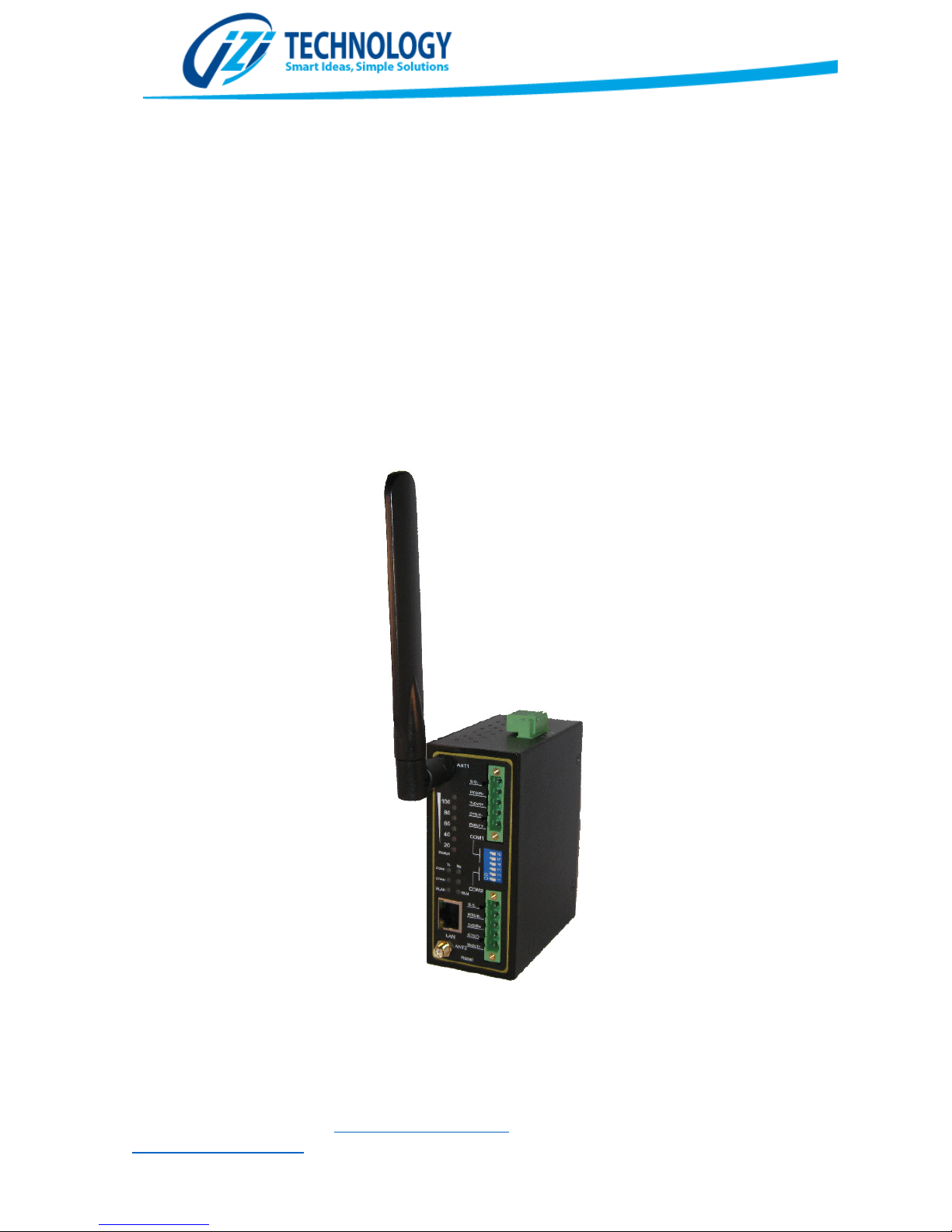
Figure
1
Product Capabilities.
The SPX5 is and Industrial Wireless Communications Gateway that allows transferring data to and
from the internal memory to other devices via all the supported industrial protocols. It also allows
wireless communications using the Wi-Fi standard. By using the friendly WEB based configuration
tool, the user can configure reads and writes using all the available industrial communication
protocols. The SPX5 can also be programmed using a simple scripting language called LUA, allowing
data conversions as well as execute event based actions upon communication exceptions or data
value based. Values retrieved trough the communication protocols can be displayed in a WEB based
HMI (Human Machine Interface) that allows monitoring the industrial process using Personal
Computers and Mobile Devices like tablets or smart phones.
IZI Technology Inc, 3651 Pegasus Dr. Ste. 117 Bakersfield, CA 93308 USA.
Tel: (661) 412-3494 -- email: [email protected]
www.izitechnology.com
Page 4
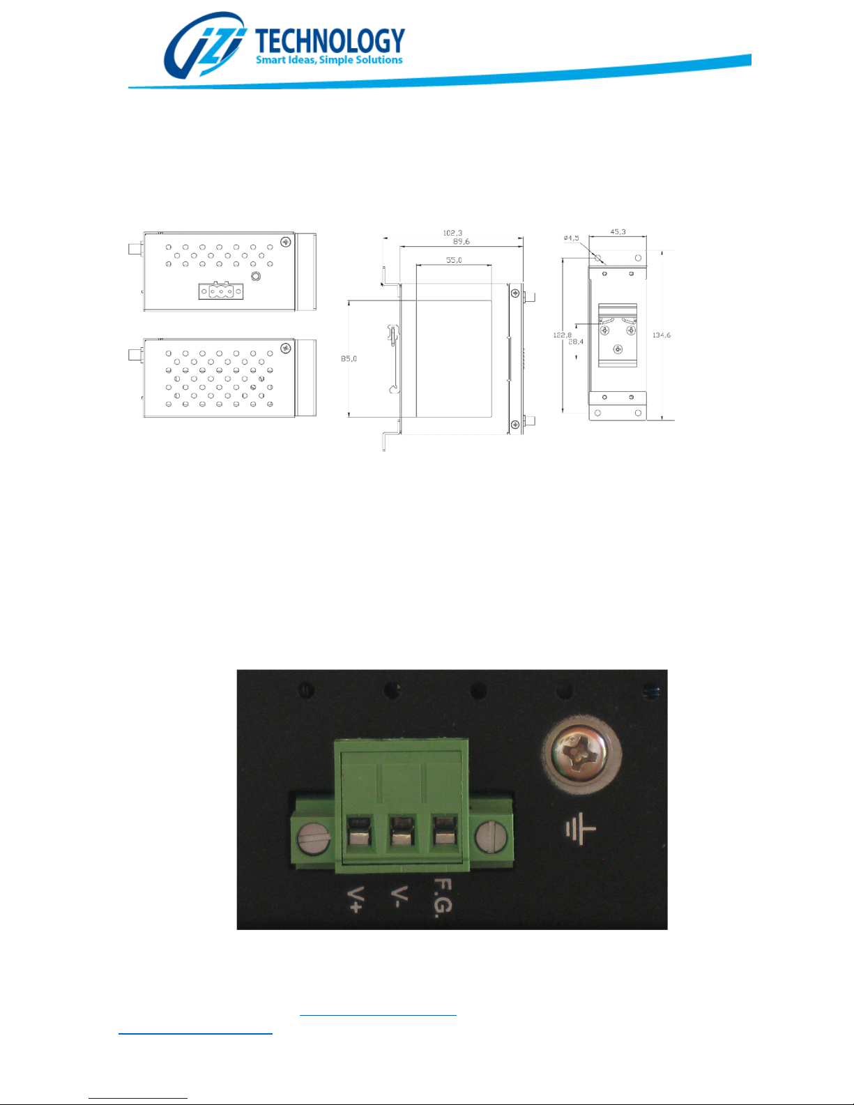
Top and Bottom View
Right Side View
View from Behind
Figure
2. SPX5
Dimensions
.
Figure
3.
Power Supply Connector Terminals Distribution.
Hardware Installation
Power Supply Connector
The SPX5 can be powered with a 9 to 48 Volts DC power supply and the maximum power
consumption is of 5Watts. The power supply connector is located on the top side of the
gateway and the terminals are shown of Figure 3. The FG terminal must be connected to
the field ground to avoid electromagnetic interference and allow all the over voltage
protections to operate properly.
IZI Technology Inc, 3651 Pegasus Dr. Ste. 117 Bakersfield, CA 93308 USA.
Tel: (661) 412-3494 -- email: [email protected]
www.izitechnology.com
Page 5
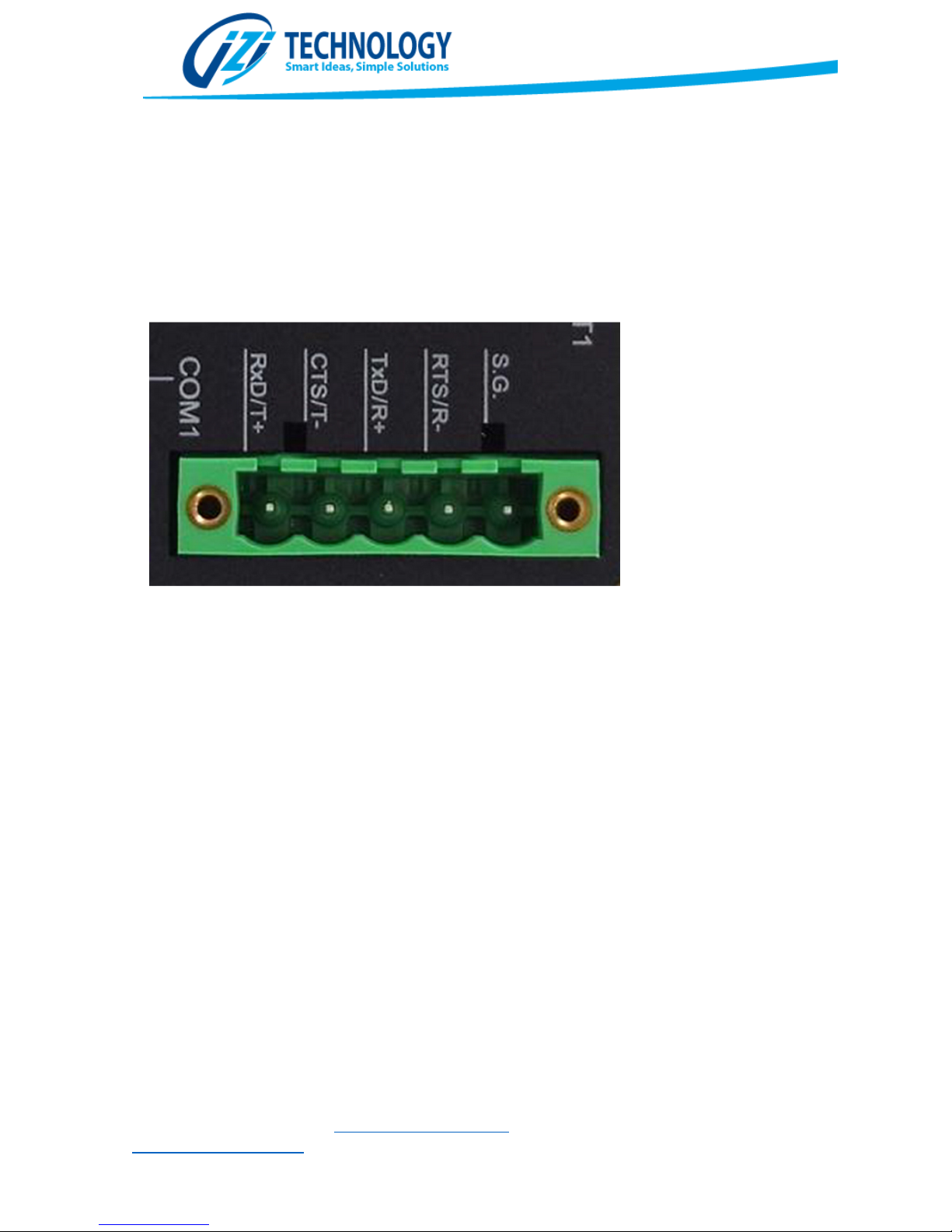
Figure
4.
Serial Network Conn
ector showing RS232/RS485 connections
Serial Ports Connectors
To connect the SPX5 to serial networks, the COM1 and COM2 connectors, shown on figure
4, are used. Terminals R- and R+ are used for transmit and receive in RS485 networks. In the
case of RS422 networks R+ and R- are used for reception whereas T+ and T- are used for the
transmission pair.
Serial Ports Configuration Switches
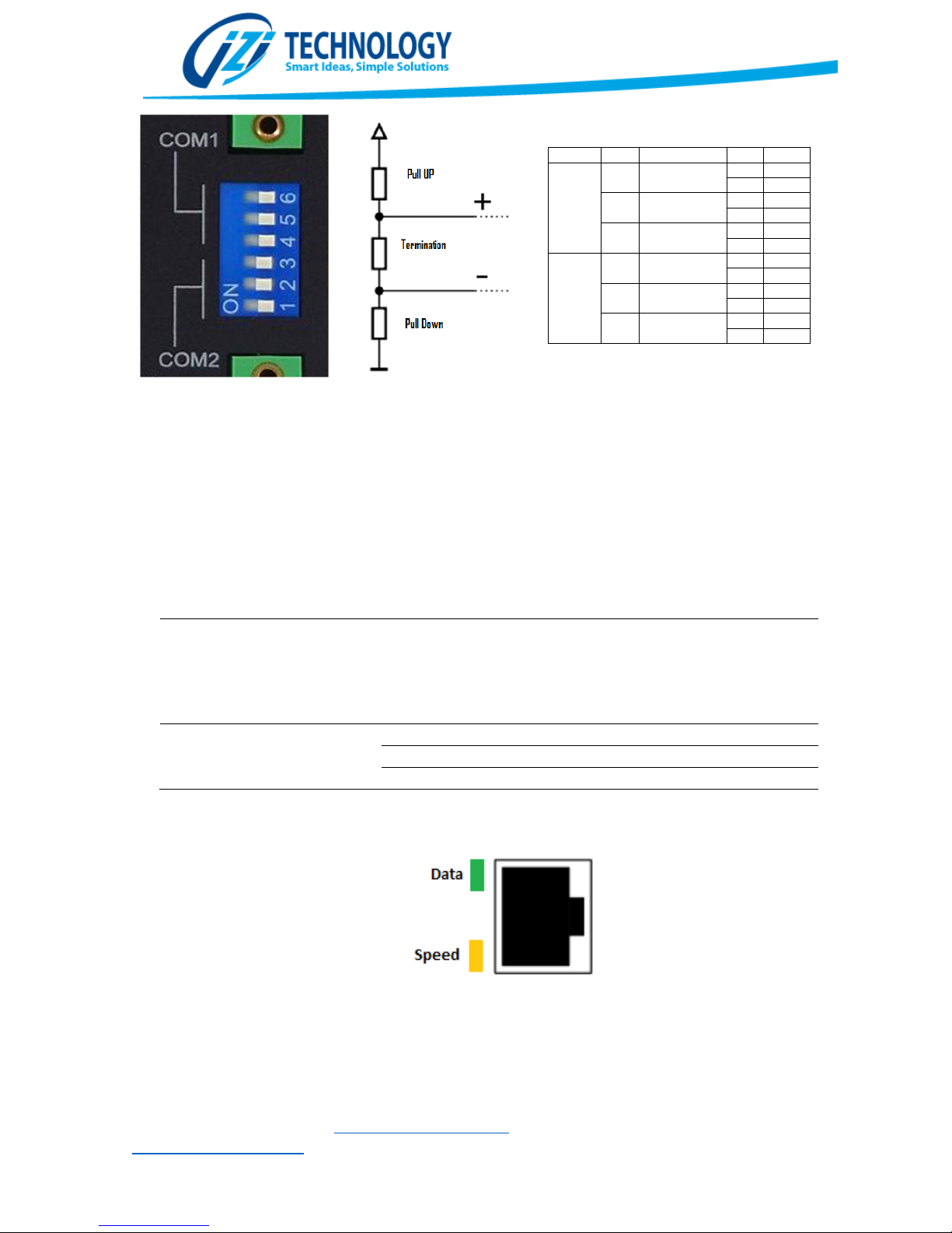
The SPX allows configuring Pull Up, Pull Down and termination resistors in the RS485/RS422
network. This configuration is done through the dip switches in the front of the equipment.
In Figure 5, the operation of the switches is shown. The recommended normal operation of
the SPX5 is having all switches OFF, however when the SPX5 is the first or last device on the
network, the termination must be switched to ON.
IZI Technology Inc, 3651 Pegasus Dr. Ste. 117 Bakersfield, CA 93308 USA.
Tel: (661) 412-3494 -- email: [email protected]
www.izitechnology.com
Page 6
COM DIP Function
SW Ω
COM1
6
Pull High
On 1K
Off 100K
5 Pull Low
On 1K
Off 100K
4 Termination
On
120
Off ∞
COM2
3
Pull High
On 1K
Off 100K
2 Pull Low
On 1K
Off 100K
1 Termination
On
120
Off ∞
Figure
5.
Serial Port Configuration Switches
.
Indication
LEDs
for the
Ethernet Port
LED Status
Description
Data
(Verde)
Off
No Ethernet connection
detected. SPX5 is not
Speed(Ambe
r) Off No
activity
On
Connected at
10 Mbps.
Blinking
Connected
at
100/1000 Mbps
Figure
6. Ethernet
Port indication Lights
Ethernet
The SPX5 has a 10/100/1000 Mb/s capable Ethernet Port. This port supports all type of network
communications like Ethernet/IP and Modbus TCP/IP. This port is also used for configuring the
SPX5 using our WEB based configuration tool.
Blinking
communicating trough the Ethernet Port.
Active data Communication trough the
Ethernet Port..
IZI Technology Inc, 3651 Pegasus Dr. Ste. 117 Bakersfield, CA 93308 USA.
Tel: (661) 412-3494 -- email: [email protected]
www.izitechnology.com
Page 7
Figura
7
. Indicadores Luminosos del SPX5
Indicator Lights.
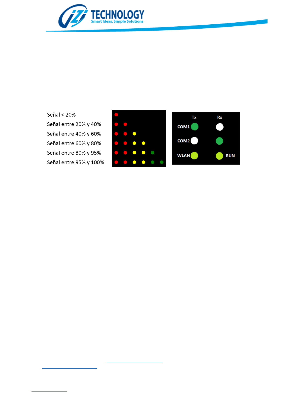
The SPX5 has two blocks of indicator lights shown on figure 7. The first block indicates Wireless
LAN communication status whereas the second indicates general status as well as serial ports
communication status.
The Wireless LAN communication status block indicates, using six LED lights, the signal strength
of the node with the lowest wireless signal quality. If all the signal quality LEDs are OFF, no nodes
are currently connected to the SPX5. The number of lighted LEDs indicates the quality of the
signal of the node with the worst signal quality, and the meaning of the number of lights can be
seen in Figure 7.
The second block of indicator lights show the transmission and reception of the serial ports as well
as general and Wireless status. A blinking TX or Rx light for COM1 or COM2 indicates that data
transfer is happening on the respective port. A solid Rx or TX line indicates a faulty connection on
the respective port. Typically a solid light is associated with a mismatched polarity of the connection
or a misbehaving node on the network.
The WLAN indicator light shows if the Wireless LAN is activated and it is transferring data. A solid
WLAN indicator means that the interface is configured but no data is being transmitted. A blinking
light means that data transfer is happening. If the WLAN indicator is off, it means that the interface
is disabled.
A slow (once a second) blinking RUN light means that the module is operating properly, while a fast
blinking (200 mSec) indicates firmware corruption and technical support must be contacted.
Reset Push Button
In figure 8, the reset push button is shown. This button is to reset the SPX5 security and to restore
factory default settings. If the button is pressed and hold for 5 seconds, all security settings
(passwords), will be reset to a disabled security. This may be necessary if the user forgets the
administration password that is required to make configuration changes. After the security is
disabled the unit will play two tones using the internal speaker.
IZI Technology Inc, 3651 Pegasus Dr. Ste. 117 Bakersfield, CA 93308 USA.
Tel: (661) 412-3494 -- email: [email protected]
www.izitechnology.com
Page 8
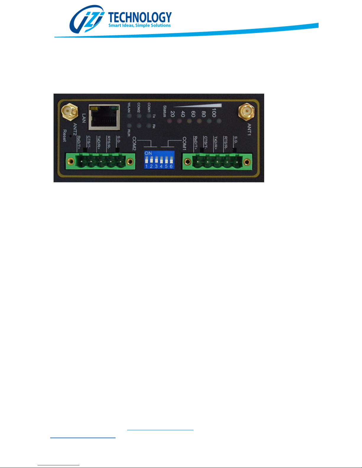
Figure 8
.
Reset Push Button Location
.
To restart the unit to factory defaults, the reset button must be pressed for 10 seconds. At this point
the internal configuration will be replaced with the factory default settings. The user may need to
do this if an invalid configuration is loaded into the module.
IZI Technology Inc, 3651 Pegasus Dr. Ste. 117 Bakersfield, CA 93308 USA.
Tel: (661) 412-3494 -- email: [email protected]
www.izitechnology.com
Page 9
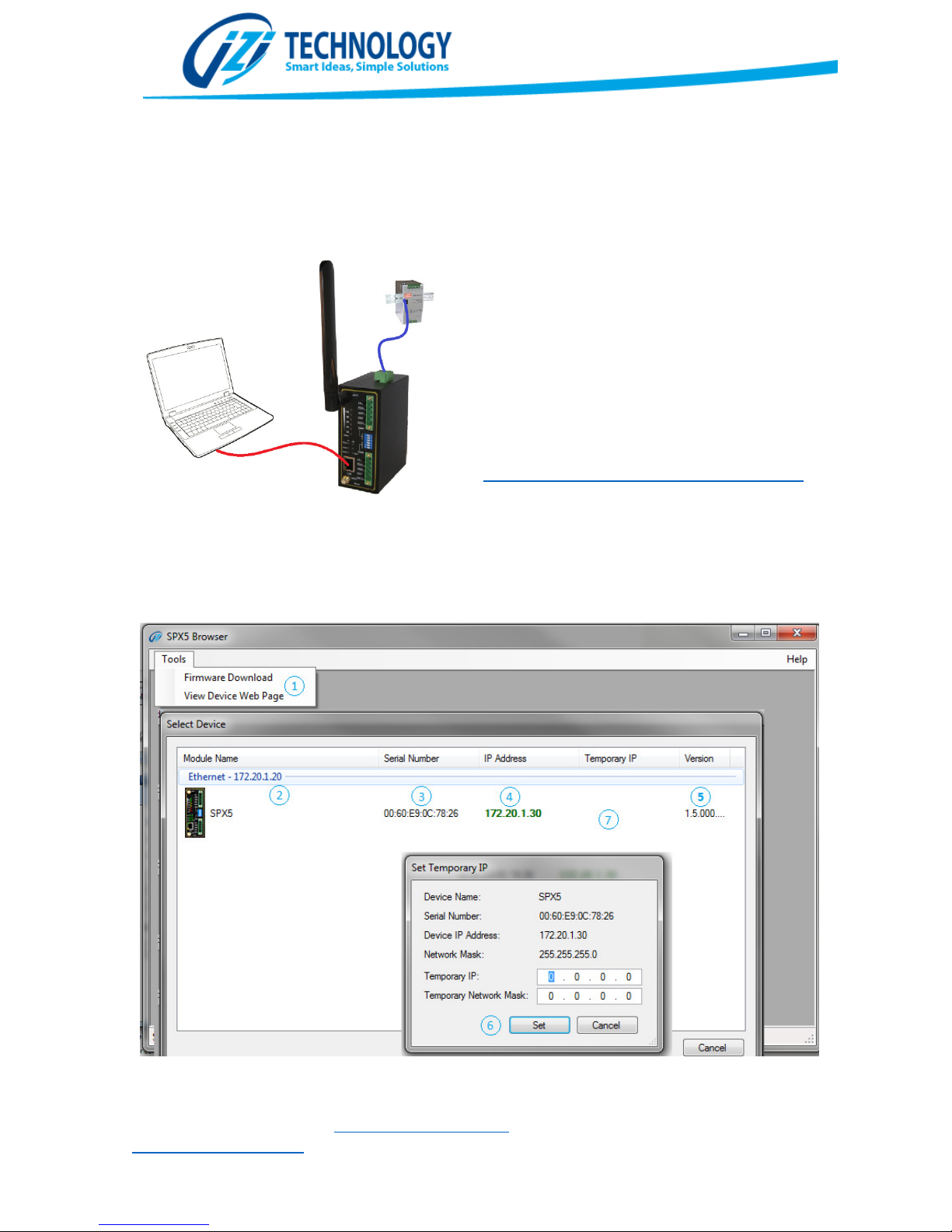
To start working with the SPX5, it must be
Figure
9. Con
necting the SPX5
Setting up the SPX5 for the first time
powered by a 9V to 48V power supply and the
Ethernet port must be connected to the
configuration personal computer.
From the IZI Technology web site download
and install the SPX5 Browser. This application is
only supported in Microsoft Windows
Operating System.
http://www.izitechnology.com/support/spx5/
When the application is installed and run for
the first time, it will show all connected SPX5 on
the network.
Figure 10. SPX5 Browser windows.
IZI Technology Inc, 3651 Pegasus Dr. Ste. 117 Bakersfield, CA 93308 USA.
Tel: (661) 412-3494 -- email: [email protected]
www.izitechnology.com
Page 10

The SPX5 Browser (Shown in figure 10) is a simple to use software that allows you to detect SPX5
devices present on the network, change or assign a temporary IP to them, and allow upgrading the
firmware version of the devices.
In order to detect an SPX5 on the network go to the menu “Tools” (1) and choose “Firmware
Download” to upgrade a gateway firmware or “View Device Web Page” to configure a gateway on
the network. After choosing any of these options a dialog will present that will show all the detected
SPX5 devices on the network. When presented, the IP Address of the PC interface at which the SPX5
is connected to will be shown (2). This allows the user to determine what is the optimal IP that can
be assigned to the SPX5 in order to access it through the network.
For each detected SPX5 on the network, the SPX5 Browser, will show: Gateway Name, Serial Number
or MAC Address (3) SPX5 Configured IP Address (4), Temporary IP Address (7) and Firmware Version
(5).
If the IP Address is shown in red, it means the IP Address of the gateway is not reachable from the
computer you are connected from. In that case you need either to change your computer IP Address
or assign a temporary IP address to the SPX5 gateway. To assign a temporary IP address to the SPX5,
right click over the gateway and select “Change Temporary IP Address”. After that, the temporary
IP change window (6) will be displayed. A new IP Address and network mask must be entered in this
window. If the new IP Address is on the same subnet as the PC, it will be possible to access the SPX5
Gateway for configuration or for firmware upgrade.
Once the SPX5 has an IP Address that is reachable from the PC, double clicking the shown gateway
will start the configuration or firmware upgrade process. In Figure 11 the main configuration web
page of the SPX5 is shown.
IZI Technology Inc, 3651 Pegasus Dr. Ste. 117 Bakersfield, CA 93308 USA.
Tel: (661) 412-3494 -- email: [email protected]
www.izitechnology.com
Page 11
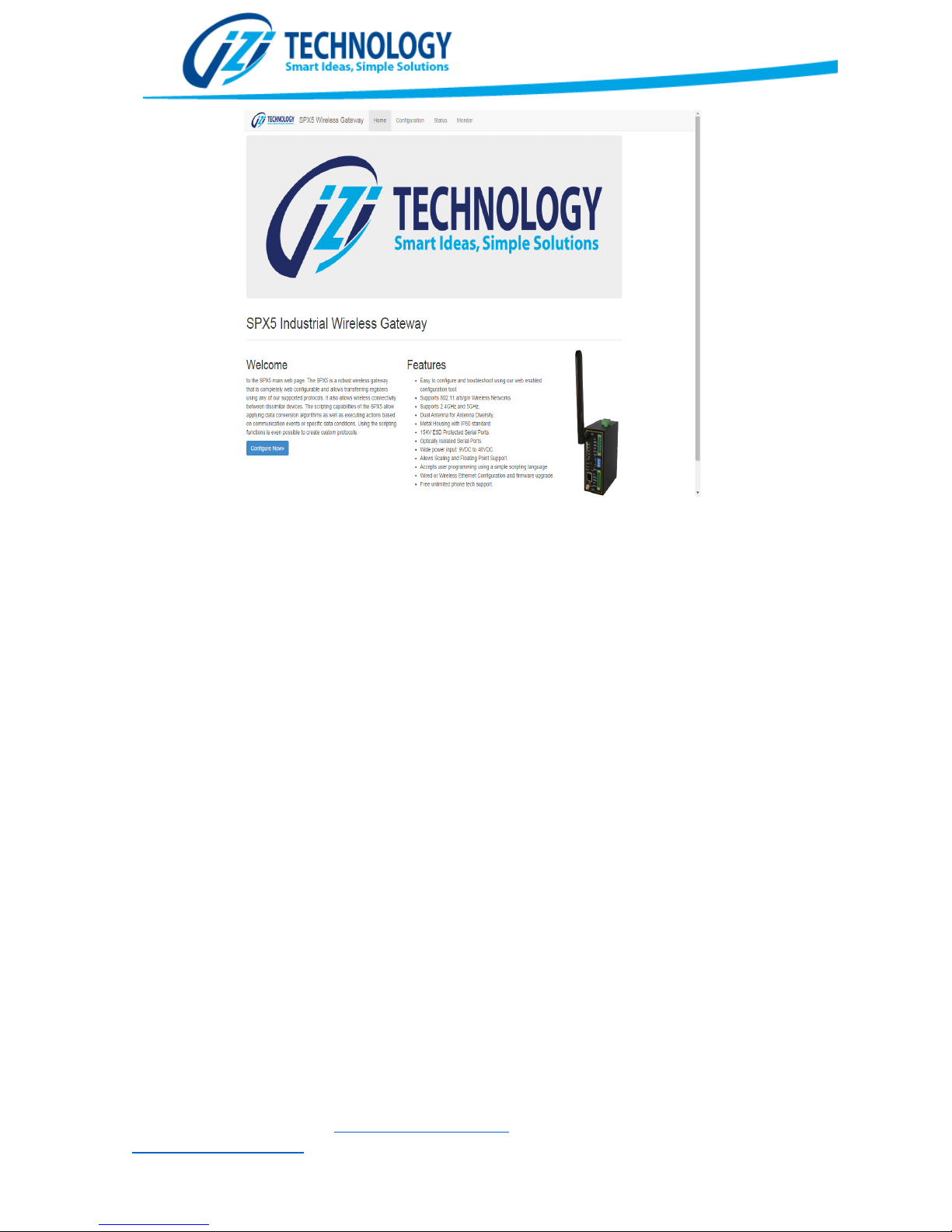
Figure
11.
Main configuration page of the SPX5
.
Operation and Configuration of the SPX5
The SPX5 is an industrial communication gateway that allows transferring value to and from its
internal database. Using any of the supported protocols, the information is read from a device and
copied in the internal memory of the SPX5. Then using another protocol that same information is
transferred to a different device.
The SPX5 also supports writing simple user scripts that allow conversion of data values or executing
logic upon communication events. There are three types of scripts available on the SPX5: Startup,
Continuous, and Fault. The Startup script is executed on startup (every time the gateway cycles
power or after configuration changes). The Continuous script executes constantly during operation,
for this reason is important to make this script in an efficient way, to avoid interrupting
communications. The Fault Script is executed if an error is found on the Continuous Script.
IZI Technology Inc, 3651 Pegasus Dr. Ste. 117 Bakersfield, CA 93308 USA.
Tel: (661) 412-3494 -- email: [email protected]
www.izitechnology.com
Page 12
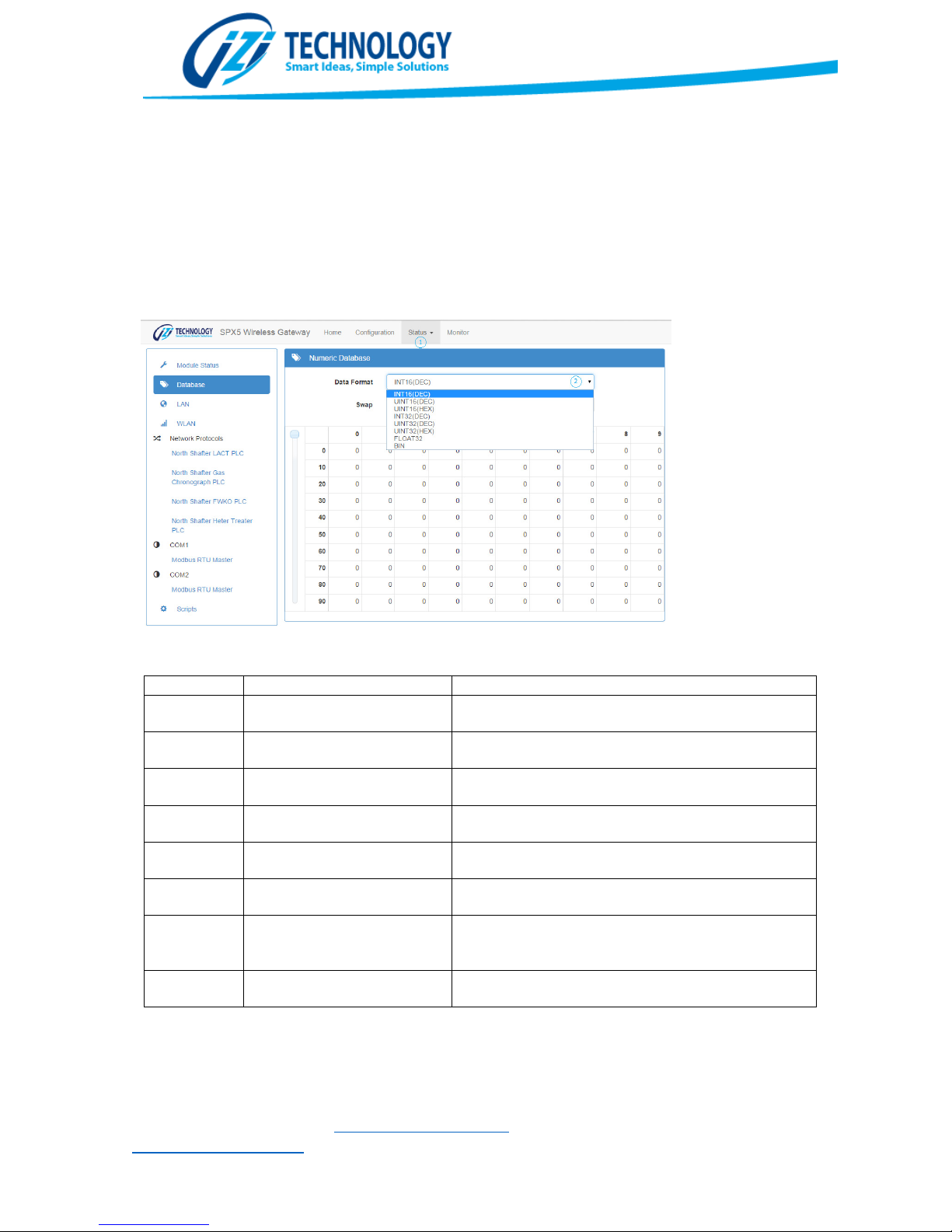
Figure
12. SPX5 Database Visualization of the Status Web Page
.
Data Base
The SPX5 contains an internal Real Time Database. This database is used to hold values retrieved
using the different available protocols. This data can also be accessed by the protocols to be
transferred to a different device.
The Status web page of the SPX5 allows viewing the Database for troubleshooting or just to view
the values retrieved by the different protocols. The Status web page (shown in Figure 12) shows the
database as an array of values with a user selectable Data Format and Byte Swapping. Table 1 shows
all the possible data types
NAME Range Description
INT16(DEC) (-32,768 hasta +32,767) 16-bit signed integer in decimal format
UINT16(DEC) 0 hasta 65,535 Unsigned 16-bit integer in decimal format
UINT16(HEX) 0 hasta 65,535 Unsigned 16-bit integer in hexadecimal format
INT32(DEC) -2,147,483,648 to 2,147,483,647 32-bit signed integer in decimal format
UINT32(DEC) 0 to 4,294,967,295 Unsigned 32-bit integer in decimal format
UINT32(HEX) 0 to 4,294,967,295 Unsigned 32-bit integer in hexadecimal format
FLOAT32 2
BIN Utiliza las 16 posiciones de
Table 1. Different type of Database values representation.
-128
memoria
hasta 2
127
Representation in 32 bits where MSB is sign, 8 bits of
exponent and 23 of mantissa
.
Binary representation of data
IZI Technology Inc, 3651 Pegasus Dr. Ste. 117 Bakersfield, CA 93308 USA.
Tel: (661) 412-3494 -- email: [email protected]
www.izitechnology.com
Page 13

The SPX5 database can be accessed from all the available protocols as well as from the scripts.
The SPX5 allows configuring three levels of security, Admin (full access), Hmiview (Allows viewing
When accessed from any protocol, the addressing used is in 16 bit Words, whereas when
accessed from the scripts, it is addressed as 8 Bit Bytes. What this means is that typically,
database addresses entered in the scripts correspond to double the number of the addresses
entered in the protocol configuration screens.
Module Configuration.
All the SPX5 configuration is made through the Configuration web page of the SPX5. Of Figure
13 the main view of the configuration web page is shown. On the left all the possible
configuration items are shown, whereas on the right the specific configuration for the chosen
item is entered. The Items shown on Figure 13 Allow configuring:
1. General Gateway Configuration: Name and Description
2. Access Security
3. LAN (Ethernet Port) and WLAN (Wireless Interface)
4. Network Protocols
5. Scripts Edition
6. Web HMI Configuration
Gateway Name and Description
This option allows setting a name and a description of this specific SPX5 gateway. This
information is available in the status tab and the SPX5 Browser and allows the user to identify
individual SPX5 as well as quickly determining what its function is.
Gateway Security Configuration
WEB HMI Screens), and HMIControl (Allows viewing and controlling from HMI Screens). The
Admin user can setup the passwords for all three users. Each password must be larger than 8
characters.
Passwords are write-only, so once they are set there is no way to view what they were set to. Also
they are not stored with the gateway configuration.
After changing the passwords a reboot is required for the changes to make effect.
IZI Technology Inc, 3651 Pegasus Dr. Ste. 117 Bakersfield, CA 93308 USA.
Tel: (661) 412-3494 -- email: [email protected]
www.izitechnology.com
Page 14
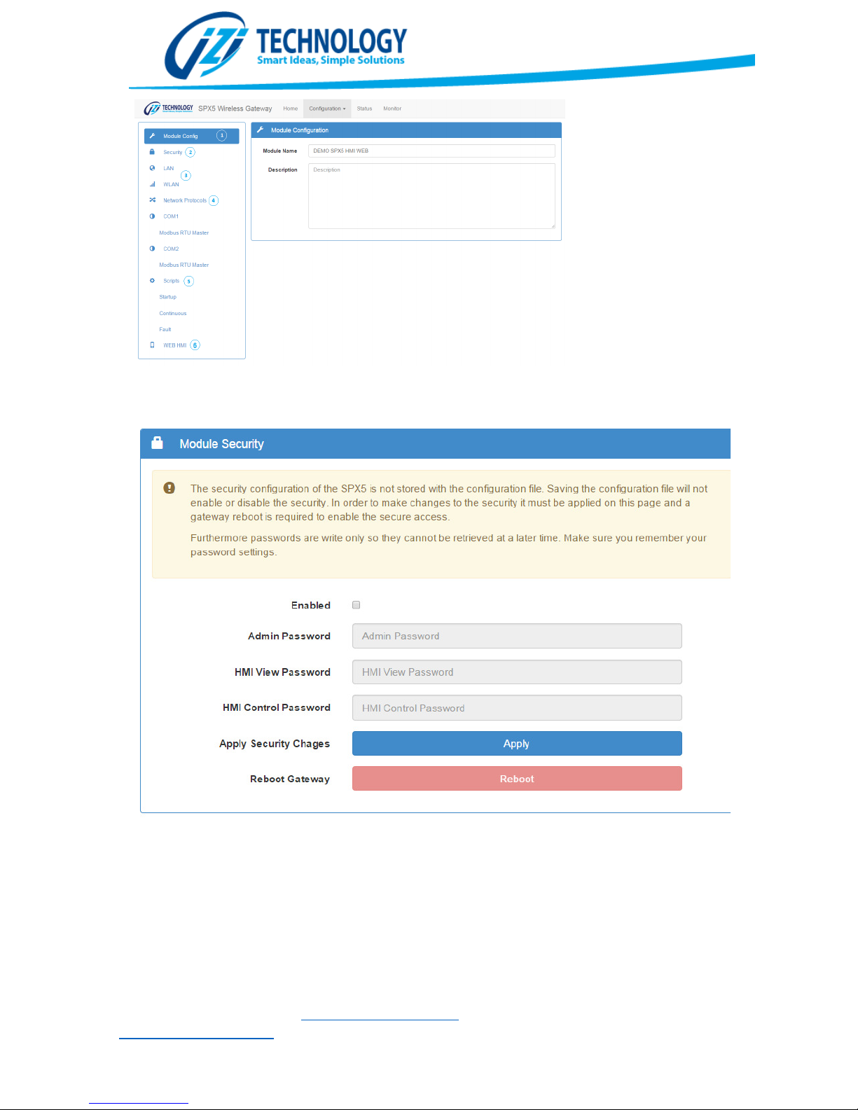
Figure
13
.
SPX5 Configuration Screen
Figura 13. SPX5 Security Configuration Screen.
Ethernet (LAN) and WiFi (WLAN) Configuration
The LAN interface (Wired Ethernet) is always enabled. The user must configure the IP Address,
network mask and default gateway. The user must carefully choose these values to allow the
SPX5 gateway to communicate through the hardwired Ethernet interface.
IZI Technology Inc, 3651 Pegasus Dr. Ste. 117 Bakersfield, CA 93308 USA.
Tel: (661) 412-3494 -- email: [email protected]
www.izitechnology.com
Page 15
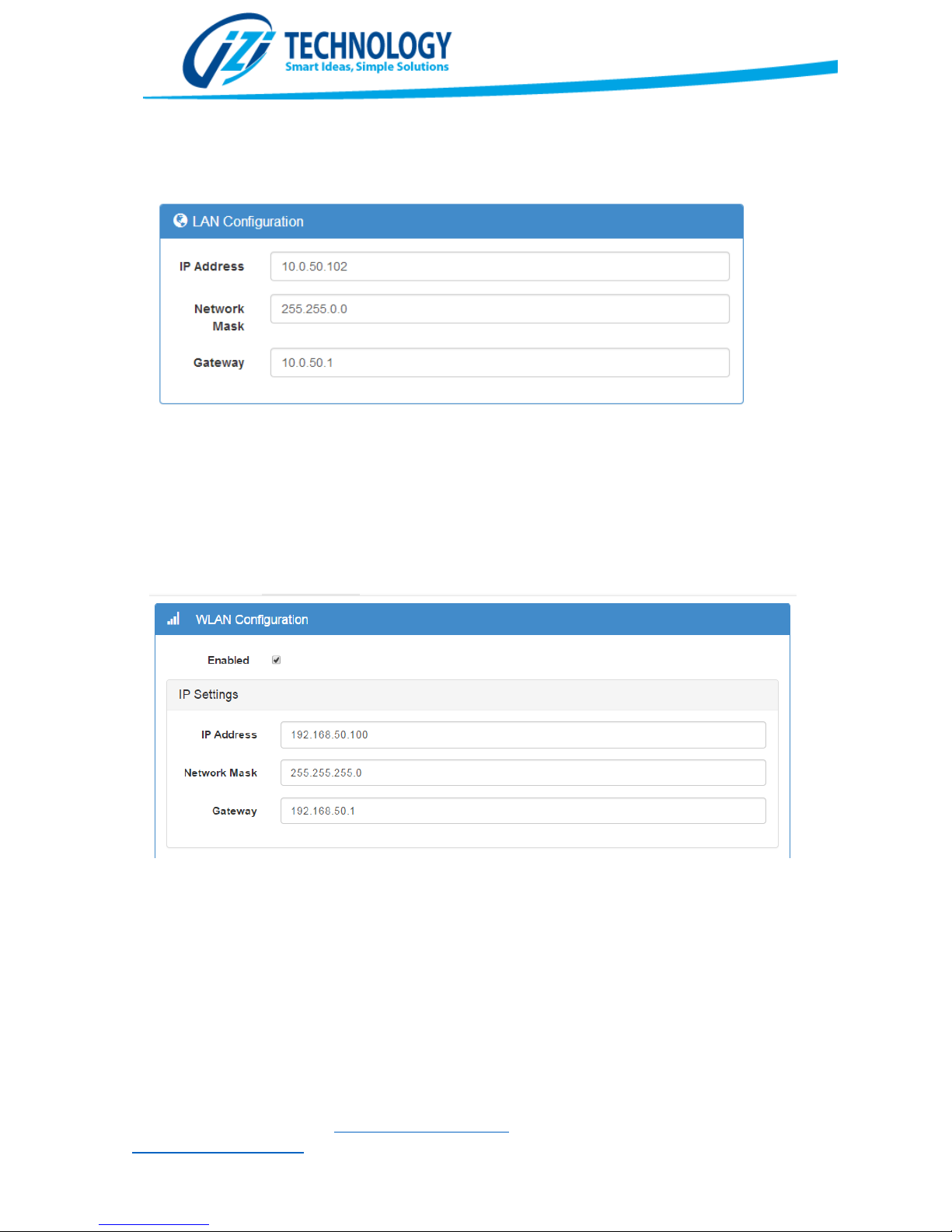
The Gateway setting is required if the SPX5 will be accessing networks outside the wireless
Figure
15. LAN Interface Configuration
Figure
16. WLAN IP Settings configuration
(WLAN) and wired (LAN) sub networks. In that case, the IP of a router connected to the LAN
interface must be specified in the Gateway setting.
The Wireless network can be enabled or disabled depending on the user requirements. The user
must specify the IP settings: IP Address, Network Mask and Gateway. It’s very important that the
settings for LAN and WLAN are in different subnets. Although a Gateway setting is present for the
WLAN, this is reserved for the future. At this point in time the network can be rerouted to other
subnets only through the LAN interface.
DHCP Server Settings:
The WLAN interface supports a DHCP Server, useful to automatically set IP Addresses of mobile
devices attached trough the WLAN Interface. It is important to set the range of IP Addresses on
the same subnet as the WLAN Interface.
IZI Technology Inc, 3651 Pegasus Dr. Ste. 117 Bakersfield, CA 93308 USA.
Tel: (661) 412-3494 -- email: [email protected]
www.izitechnology.com
Page 16
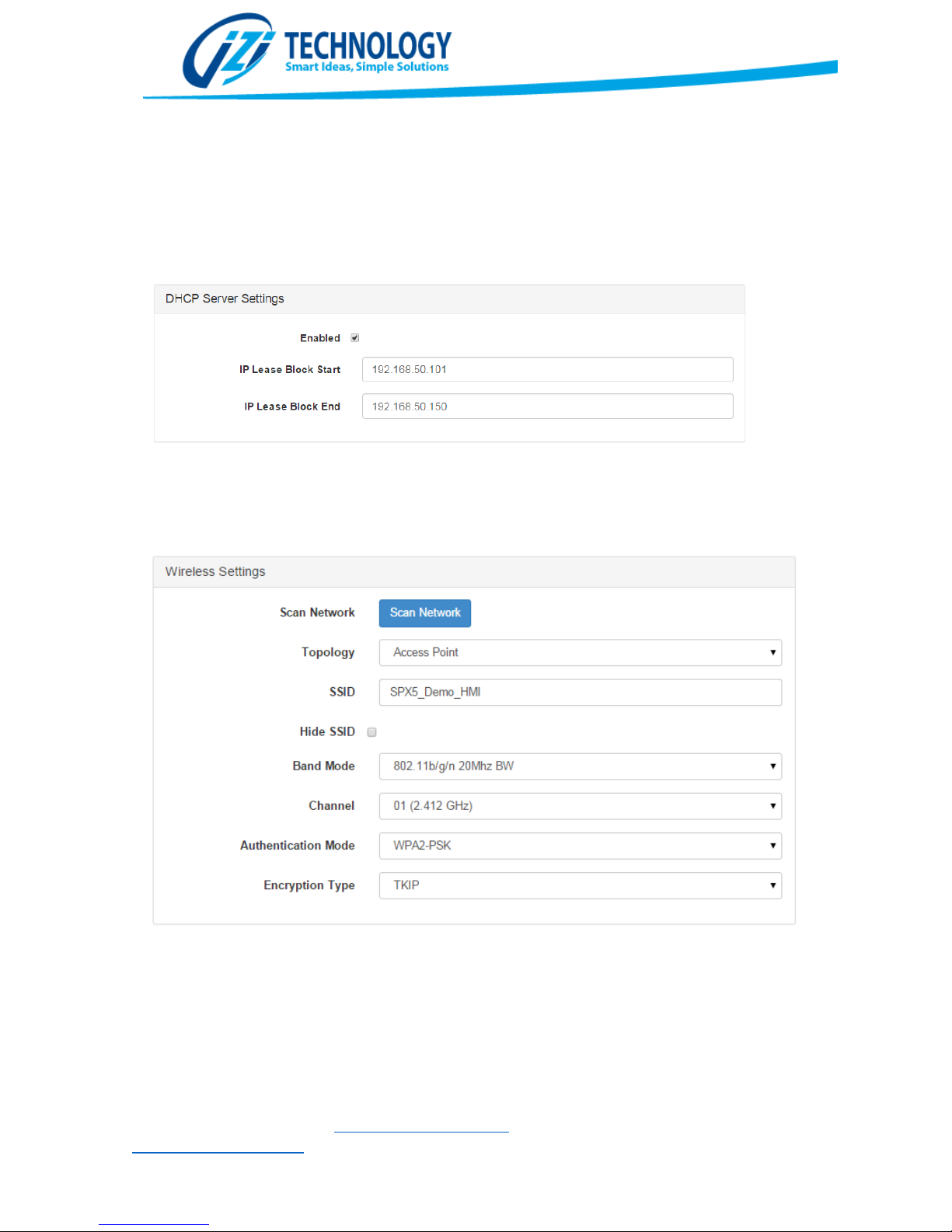
Figure
17. DHCP Server
Configuration
Wireless Settings:
In the Wireless Settings section it is possible to configure all the WiFi settings. Based on the
selected Topology (AdHoc, Infrastructure, or Access Point) the possible options change. When
Infrastructure is selected, it is possible to use the Scan Network button to browse existing WiFi
Networks in the vicinity of the gateway. Based on that is possible to choose an existing network
and connect to it.
IZI Technology Inc, 3651 Pegasus Dr. Ste. 117 Bakersfield, CA 93308 USA.
Tel: (661) 412-3494 -- email: [email protected]
www.izitechnology.com
Page 17
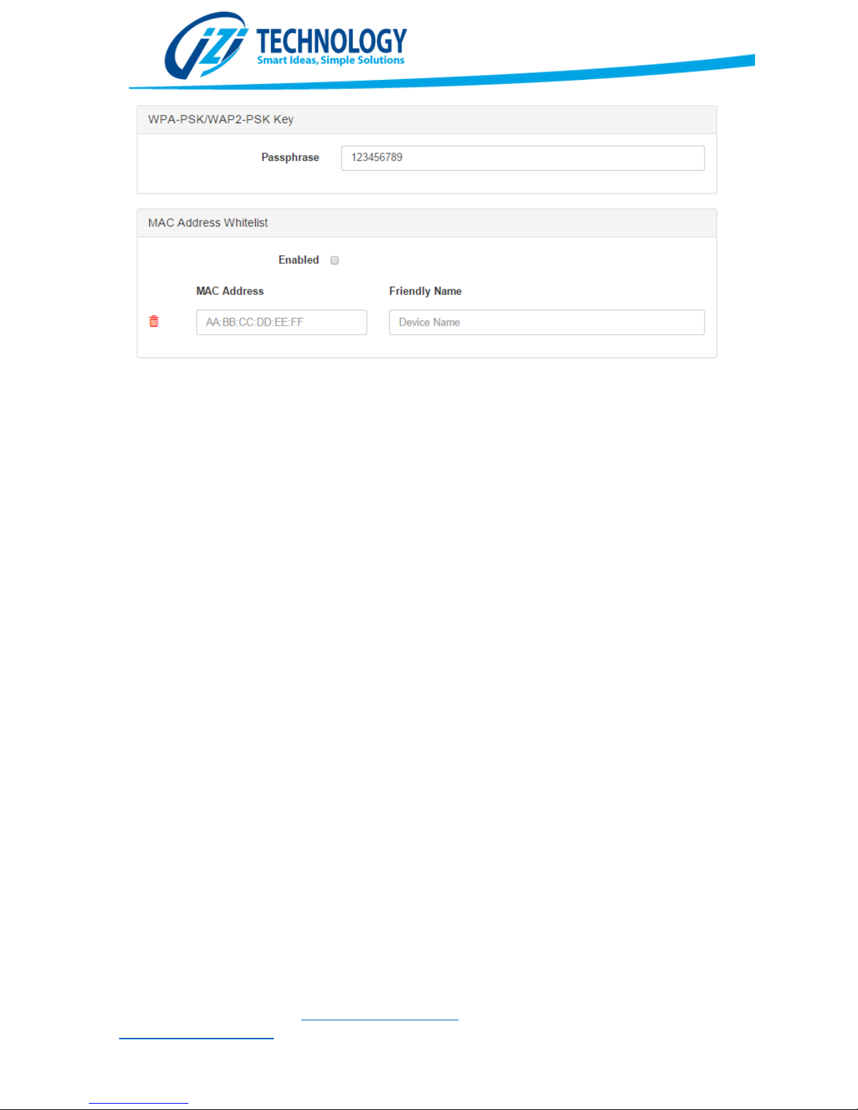
Figure 18
.
Wireless LAN
Configuration Sections
Depending on the type of encryption in the network the user will have to enter a Passphrase. The
Passphrase is the network encryption key and it must be 9 characters or longer.
MAC Address Whitelist:
When enabled, this option only allows devices with the entered MAC address to connect to the
SPX5. The friendly name is a guide for the user to enter the device that contains that MAC
Address.
Network Protocols Configuration
At this moment there are four types of network protocols that can be configured on the SPX5:
Modbus TCP/IP Client, Modbus TCP/IP Server, Ethernet/IP Tag Based Client and NTP (Network
Time Protocol). It is very important to indicate that all these protocols can be enabled at the same
time or even multiple instances of some of these protocols can be enabled at the same time. For
example it is possible to enable multiple Modbus TCP/IP Clients to more efficiently connect to
several Modbus Devices. Server protocols only support one instance at a time.
Every protocol added has a General Settings section where a name and a comments area is
available for the user to comment about the use of that specific protocol.
IZI Technology Inc, 3651 Pegasus Dr. Ste. 117 Bakersfield, CA 93308 USA.
Tel: (661) 412-3494 -- email: [email protected]
www.izitechnology.com
Page 18
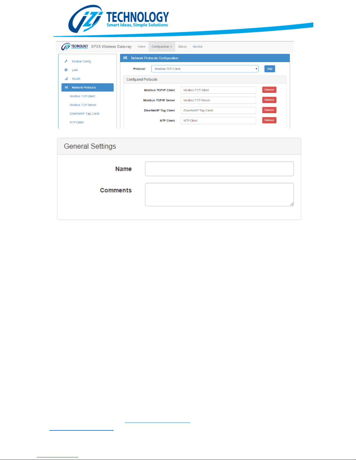
Figure
19. Protocol Configuration Screen
.
Modbus TCP/IP Client Protocol
To configure the Modbus TCP/IP Client, the user must specify data transfer blocks or
commands. Each one of those data transfer blocks specifies a block of data that is transferred
to/from a Modbus TCP/IP device and to the SPX5 Internal database. Each one of those transfers
are executed automatically according to the specified poll time.
Figure 20 shows the “Protocol Settings” section of the Modbus TCP/IP Client Configuration. Three
values can be set in this section: 1. Time Out, 2. Retry Count, and 3. Back Off. The Modbus TCP
IP Client waits a ”Time Out” amount of milliseconds for a response. If a response is not obtained
in this time, the command will be retried “Retry Count” times. After this number of retries the
command is flagged in error. After an error, the Modbus TCP/IP Client will wait “Back Off” number
of seconds before polling that device again. A correct setting of these parameters avoids wasted
time in devices that are not present on the network.
IZI Technology Inc, 3651 Pegasus Dr. Ste. 117 Bakersfield, CA 93308 USA.
Tel: (661) 412-3494 -- email: [email protected]
www.izitechnology.com
Page 19
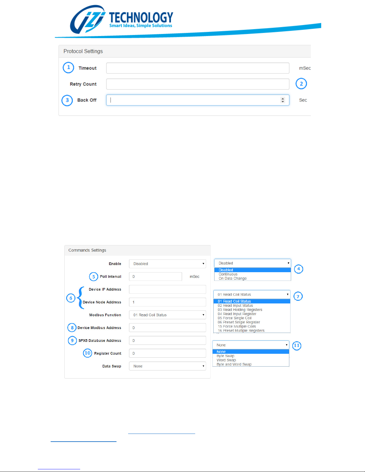
Figure
20. Modbus TCP/IP Configuration. Protocol Settings Section.
Figure
21.
Modbus TCP Client Command C
onfiguration
After configuring the Protocol Settings, the user has to add Data Mapping Blocks or Commands.
This is done using the buttons on the Data Mapping Section. When a Command is added or edited,
the window shown in Figure 21 is shown. The Enable parameter selects the enable type of the
command being edited. The options are:
Disabled: The Command is never executed. This is used to disable commands that might not be
needed but the user doesn’t want to remove for future use.
Continuous: The command will be executed continuously according to the Poll Interval.
On Data Change: The command will be sent when its associated data changes. This only works for
write commands and allows improving the protocol throughput by only sending commands when
the data changes.
The Poll Interval parameter specifies how often, in milliseconds, this command will be polled. If
for example the Poll Interval is set to 100, the command will be executed every 100 milliseconds.
Parameter (6) Device IP Address y Device Node Address, allows setting the address of the
Modbus TCP IP Server that the user wants to access with this command. The SPX5 automatically
IZI Technology Inc, 3651 Pegasus Dr. Ste. 117 Bakersfield, CA 93308 USA.
Tel: (661) 412-3494 -- email: [email protected]
www.izitechnology.com
Page 20

routes
Modbus TCP/IP messages
through
the correct interface (LAN or WLAN) depending on the
IP address configured here. If the IP address is not on any of the WLAN or LAN interfaces subnet,
then it is routed through the LAN default gateway. The Device Node Address is the specific
Modbus device inside the Server. Most Modbus TCP/IP Servers ignore this parameter and some
other use it to route to a different interface. Consult your Modbus Server User Manual to
determine the use of this parameter.
Modbus Function allows you selecting the Modbus function that you want this command to
execute. The available options are the 8 most commonly used Modbus functions.
The parameter 8 Device Modbus Address the user has to enter the 0 based Modbus offset of the
register that wants to be read or written. For example to enter Modbus address 40001, the user
needs to select function 3 Read Holding Registers and enter Device Modbus Address 0.
The parameter 9 SPX5 Database Address is the 16-bit word address of the SPX5 Database register
associated with this command. For read commands, the information will be copied in the
specified address. For write commands, this is the database location where the data will come
from.
Parameter 10 Register Count is the number of registers to read or write with this command. For
bit commands is the number of bits. For word commands, this parameter represents the number
of words.
Parameter 11 Data Swap allows selecting a byte swapping strategy. Because some devices that
implement the Modbus protocol use different byte alignments to represent its data, this
parameter allows two devices that use different alignment to communicate to each other.
Modbus TCP/IP Server Protocol
IZI Technology Inc, 3651 Pegasus Dr. Ste. 117 Bakersfield, CA 93308 USA.
Tel: (661) 412-3494 -- email: [email protected]
www.izitechnology.com
Page 21
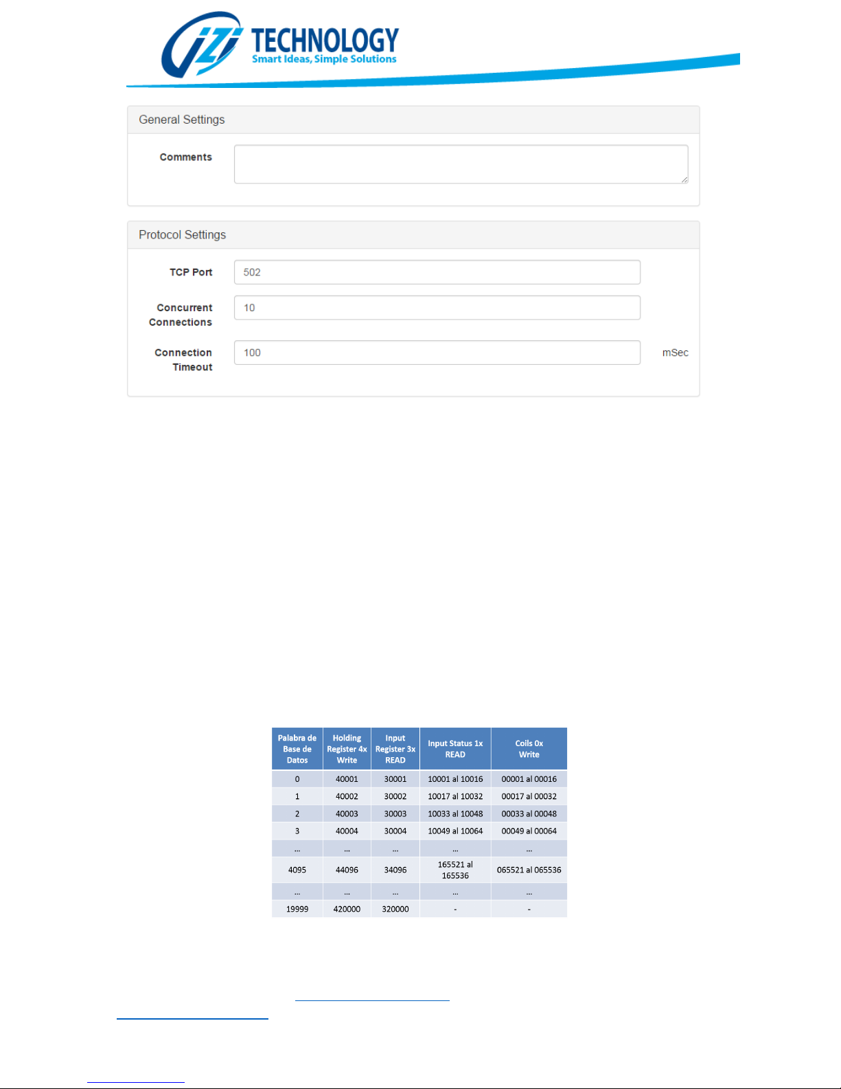
Figure
22.
Modbus TCP/IP Configuration Window
Figure
23.
Mapping of Modbus registers to SPX5 database registers
.
The TCP Port parameter allows selecting the Modbus TCP/IP Port. This parameter is configured by
default for port 502 (standard Modbus TCP port).
The “Concurrent Connections” allows configuring the maximum number of concurrent connections
allowed by the protocol.
The “Connection Timeout” is the time with no data in a TCP connection before closing the
connection. The recommended value for this parameter is 10000 mSec.
By default all the SPX5 Database memory is mapped into Modbus Registers. Figure 23 shows the
mapping between Modbus registers and addresses on the SPX5 internal database.
As an example, word 0 of the database, will be Holding Register 40001 or it can be read as well as
16 “Coils” from 00001 to 00016. Word 1 of the database can be read as “input register” 30002 or
“input status” 10017 to 10032.
IZI Technology Inc, 3651 Pegasus Dr. Ste. 117 Bakersfield, CA 93308 USA.
Tel: (661) 412-3494 -- email: [email protected]
www.izitechnology.com
Page 22

Ethernet/IP Tag Client
Like in the other protocols configuration, the user has to define data transfer blocks in the
Ethernet/IP Tag Client to transfer a PLC Tag Data to or from the SPX5 internal database.
In figure 24 the “Protocol Settings” section is displayed. These settings identify the Allen Bradley
PLC that the user wants to access and general communication settings. These are the configuration
parameters available in this section:
PLC IP Address: This is the IP Address of an Allen Bradley Ethernet interface card on the same chassis
as the PLC that the user wants to access.
Processor Slot: This is the slot where the PLC resides on the rack. For PLCs with no movable racks
(like MicroLogix and CompactLogix) 0 must be used.
Conn. Timeout: This is the connection timeout when trying to connect to the specified PLC.
Msg. Timeout: This is the timeout from messages on an open PLC Connection.
Like in the other protocols configuration, the user has to define data transfer blocks in the
Ethernet/IP Tag Client to transfer a PLC Tag Data to or from the SPX5 internal database. To create
transfer blocks the buttons in the Data Mapping section are used. When adding or editing a new
data transfer the Tag Setting section will show. This is the detail of all possible configuration
parameters in this section:
Enable: The enable parameter has three options: Disabled: This is used to disable a data transfer
when the user doesn’t require the command to be executed but doesn’t want to remove it. Enabled:
The data transfer will be executed continuously. On Data Change: The data transfer will happen only
when data changes. This option only works on Writes.
Data Direction: Defines if the configured data transfer will be a Read of PLC data or a Write to the
PLC.
Tagname: This is the name of the tag that the user wants to read or write from the Allen Bradley
PLC. The tag must be defined as a Controller Tag on the PLC. The format for the tag name follows
the standard format defined for Allen Bradley Logix PLCs. Examples of tag names are: tag,
tag.element, tag[index], tag[index].element[index].element.
Data Type: This is the type of the element that is read from the PLC. If the specified data type of the
tag doesn’t match during the execution of the command, the data transfer will fail.
Register Count: For accessing tag elements that are not arrays this parameter must be always 1. If
the accessed element of a tag is an array, then this parameter is the number of elements to be read
from that array. If for example the user has a Controller Array Tag with the name EXA and the user
wants to read 20 elements, starting with element 100 up to element 119, then the user will have
to enter a configuration like shown on Figure 25.
IZI Technology Inc, 3651 Pegasus Dr. Ste. 117 Bakersfield, CA 93308 USA.
Tel: (661) 412-3494 -- email: [email protected]
www.izitechnology.com
Page 23
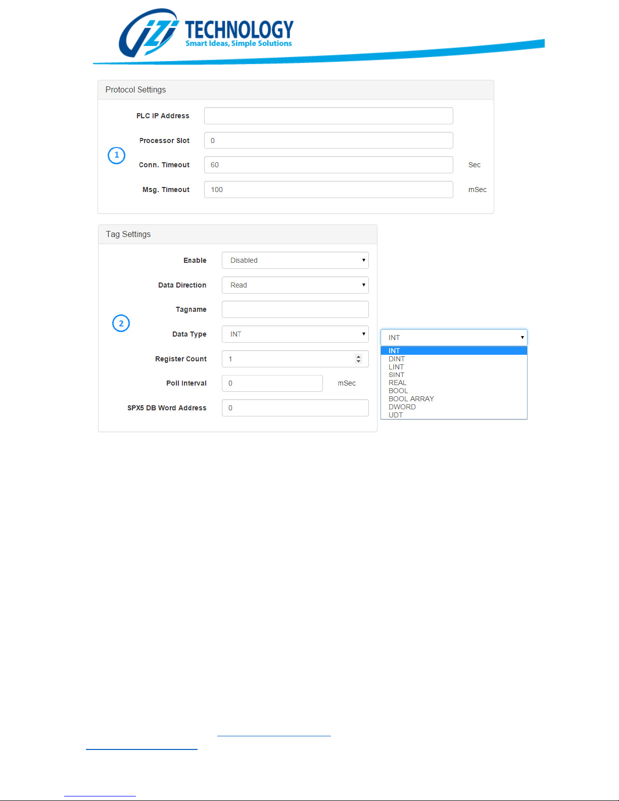
Figure 24
.
IZI Technology Inc, 3651 Pegasus Dr. Ste. 117 Bakersfield, CA 93308 USA.
Tel: (661) 412-3494 -- email: [email protected]
www.izitechnology.com
Page 24
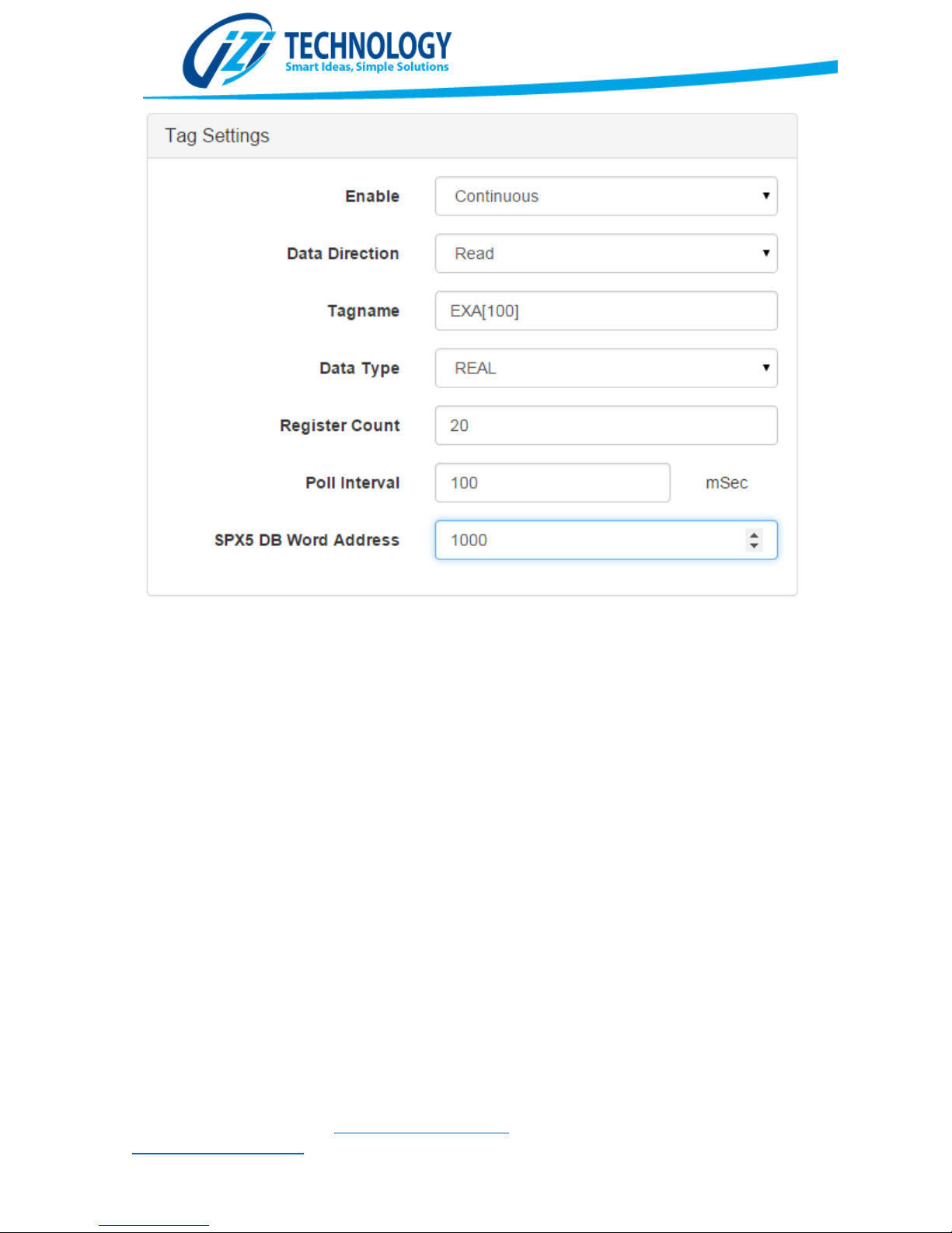
Figure
25.
Example of
Array Tag read from an Allen Bradley PLC.
If the Array Tag to be read is a bool array, then the count represents the number of 32 Boolean
blocks to read. On Figure 26 an example is shown that will read 64 bits from a Boolean Array Tag
names EXABOOL. These 64 bits will be copied in the SPX5 internal database word 70.
IZI Technology Inc, 3651 Pegasus Dr. Ste. 117 Bakersfield, CA 93308 USA.
Tel: (661) 412-3494 -- email: [email protected]
www.izitechnology.com
Page 25
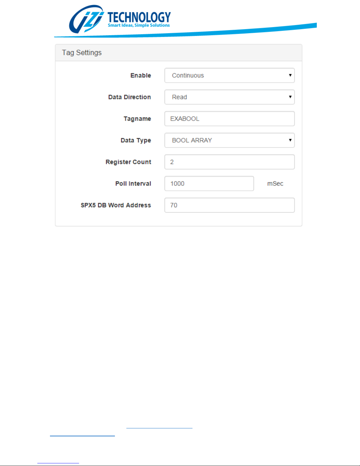
Figure
26.
Boolean Tag Read Example
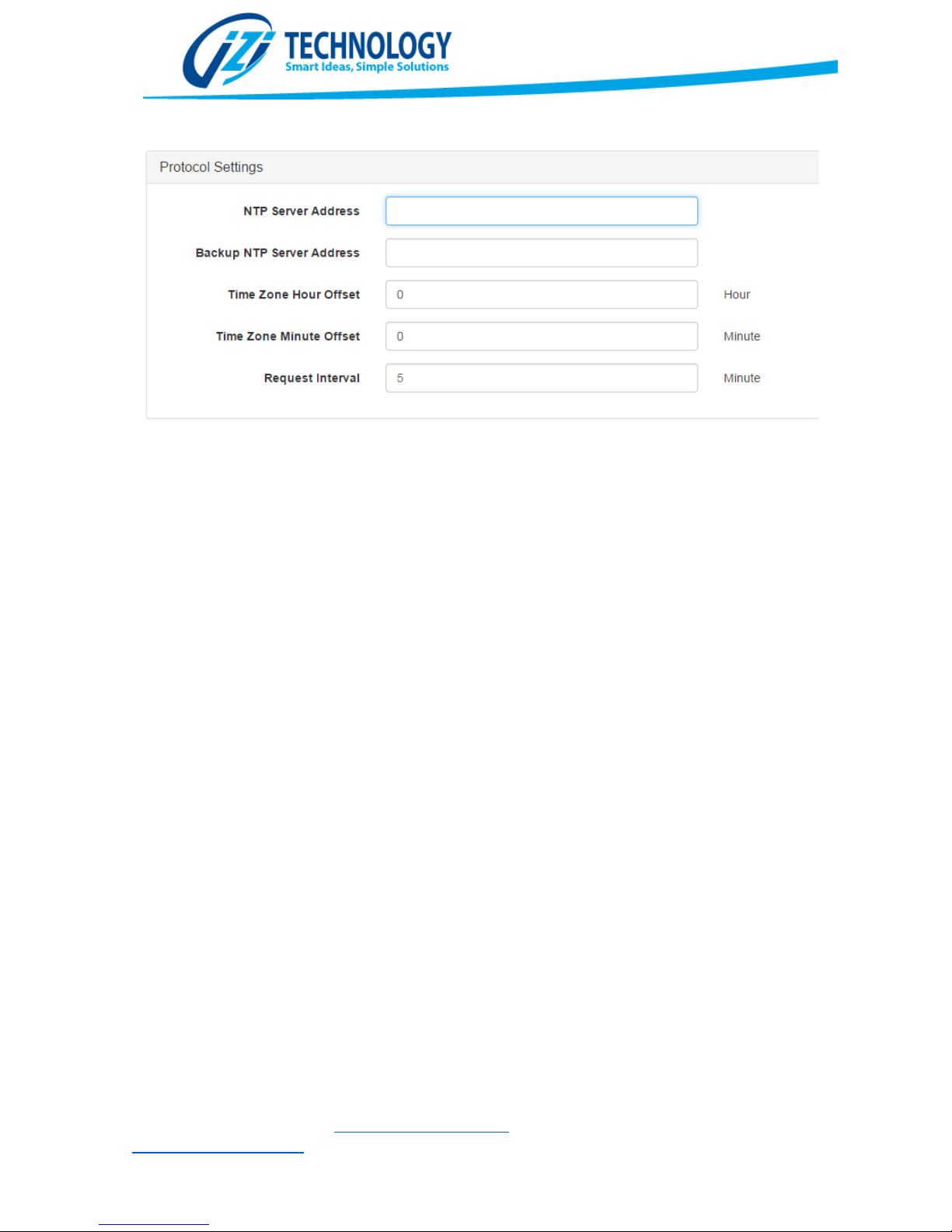
NTP Protocol
The SPX5 can be configured to use an external NTP server to synchronize Date and Time. Figure 27
shows the configuration screen of the NTP Client Protocol.
These are the parameters that must be configured for the NTP Client Protocol:
NTP Server Address: This corresponds to the IP Address of the Main NTP server. In normal
operation, the Date and Time will be requested from this server and updated internally.
Backup NTP Server Address: This is the IP Address of an NTP Server to be used as a backup in case
the main NTP Server stops responding to the date and time requests. If no Backup Server is available
use the same IP Server of the Main NTP Server in this parameter.
Time Zone Hour Offset and Time Zone Minute Offset: These parameters correspond to the offset
from GWT time for the location where the gateway is installed.
Request Interval: How frequently (in minutes) the time will be updated from the server.
IZI Technology Inc, 3651 Pegasus Dr. Ste. 117 Bakersfield, CA 93308 USA.
Tel: (661) 412-3494 -- email: [email protected]
www.izitechnology.com
Page 26
Figure
27.
NTP Client Configuration Screen
Serial Protocol Configuration
Modbus RTU Master Configuration
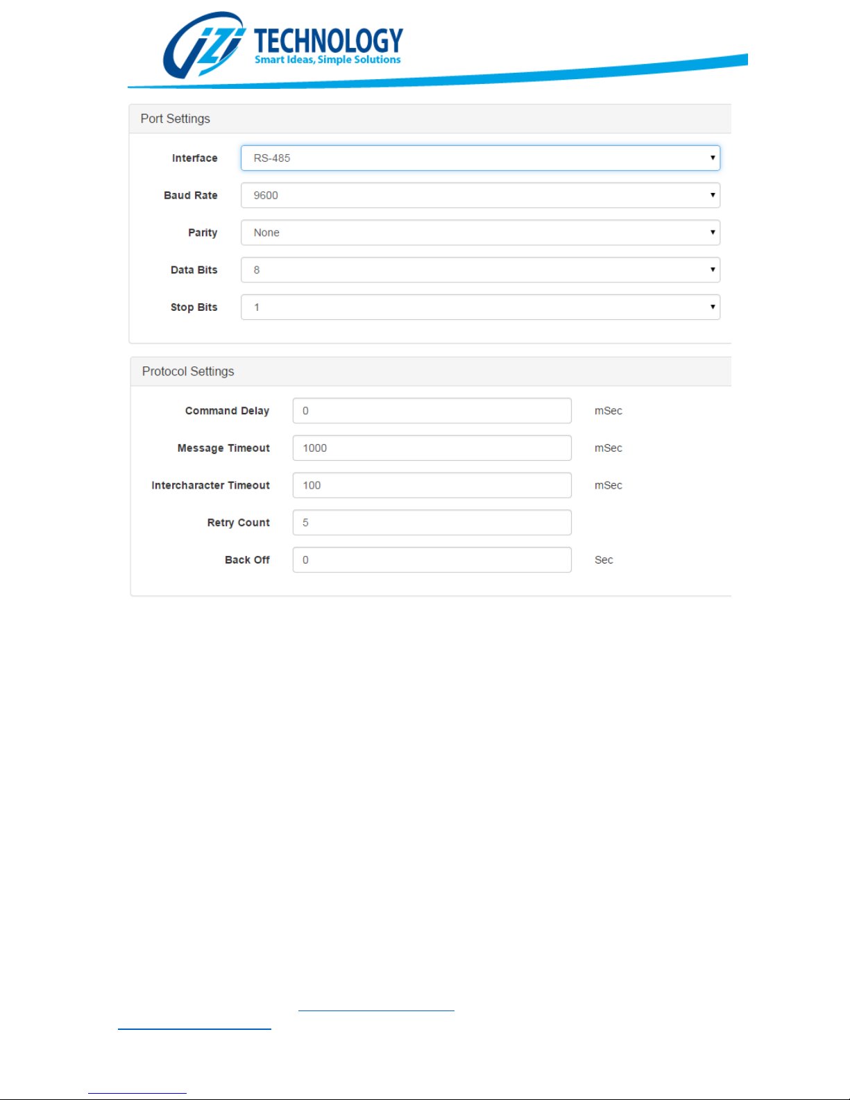
In figure 28, the Modbus RTU Master Protocol Configuration Screen is shown. In the Port
Settings section the user selects the physical interface to use, the baud rate, parity, data bits
and stop bits. These settings must match exactly those from the Modbus RTU Slaves that want
to be accessed.
In the Protocol Settings section the user can setup the following parameters:
Command Delay: This is a minimum delay to introduce between consecutive Modbus Polls. This
time is entered in Milliseconds and helps dealing with Modbus devices that are not able to
execute commands at a very fast rate.
Intercharacter Timeout: Maximum time to wait for a message from a slave device. Messages
that takes longer than this value are considered in error.
Retry Count: Maximum number of retries to a device when it is in error.
Back Off: Number of seconds that a device will be kept out of scan after it enters into error
state.
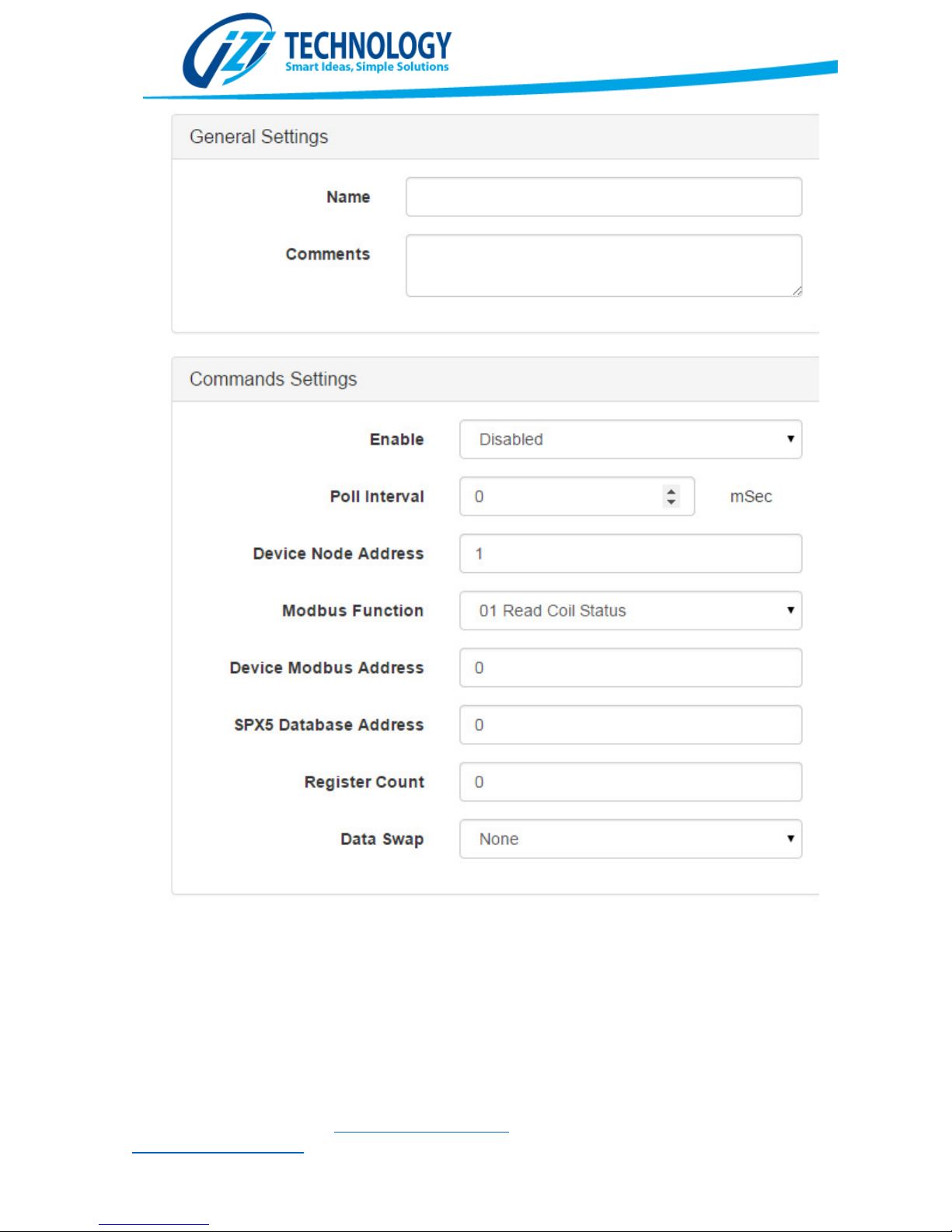
After configuring the Protocol Settings, the user has to add Data Mapping Blocks or Commands.
This is done using the buttons on the Data Mapping Section. When a Command is added or
edited, the window shown in Figure 29 is shown.
IZI Technology Inc, 3651 Pegasus Dr. Ste. 117 Bakersfield, CA 93308 USA.
Tel: (661) 412-3494 -- email: [email protected]
www.izitechnology.com
Page 27
Figure
28. Modbus RTU Master Configuration Screen
IZI Technology Inc, 3651 Pegasus Dr. Ste. 117 Bakersfield, CA 93308 USA.
Tel: (661) 412-3494 -- email: [email protected]
www.izitechnology.com
Page 28
Figure
29. Configuring Modbus RTU
Commands
IZI Technology Inc, 3651 Pegasus Dr. Ste. 117 Bakersfield, CA 93308 USA.
Tel: (661) 412-3494 -- email: [email protected]
www.izitechnology.com
Page 29

User Programmable Scripts
The User Programmable Scripts are programmed using Lua. Lua is mature easy to use scripting
language that is used in many products.
Covering the language is out of the scope of this manual but many tutorials and programming
guides can be found on the Internet. The main website for the Lua language is www.lua.org
Examples of Useful Lua Scripts
Actions at Constant Intervals
To time actions at constant intervals, the user can use this snippet of code:
Startup
initialTime = os.time()
Continuous
if os.difftime(os.time(),initialTime)>1 then
initialTime = os.time()
-- Your script action goes in here
end
In the Startup Script an initialTime Variable is declared. This variable will contain the last time the
action has been executed.
In the Continuous Script the script checks how much time has elapsed since the last time that the
action was executed. If the time exceeds one second, then the user script is executed. For other
times, just replace the number 1 by the time you require.
Read and Write of the SPX5 Database values
This example takes a unsigned integer from Word 80 on the internal database and copies it into
Word 90. The functions that will be used for this example are:
mainDatabase:getUINT16(index,swapCode) and mainDatabase:setUINT16(index,value). In both
functions index corresponds to the database address in bytes.
Continuous
local input =mainDatabase:getUINT16(2*80,0)
mainDatabase:setUINT16(2*90,input)
IZI Technology Inc, 3651 Pegasus Dr. Ste. 117 Bakersfield, CA 93308 USA.
Tel: (661) 412-3494 -- email: [email protected]
www.izitechnology.com
Page 30
Figure
31.
Configuration of the
Ethernet
/IP Data Transfer of a converted value
Math Functions over Database Values
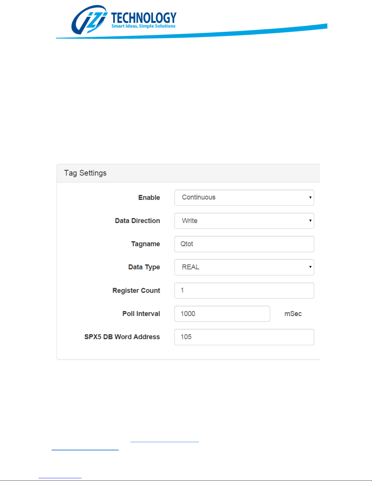
For this example an unsigned integer value from the SPX5 database word address 100 will be read
and the square root of the value will be set in word address 105 in floating point format. The value
in address 105 will be sent to an Allen Bradley PLC named Qtot.
Continuous
local input
output= math.sqrt (input)
mainDatabase:setFLOAT(2*105,output,0)
=mainDatabase:getUINT16(2*100,0)
IZI Technology Inc, 3651 Pegasus Dr. Ste. 117 Bakersfield, CA 93308 USA.
Tel: (661) 412-3494 -- email: [email protected]
www.izitechnology.com
Page 31
Figure
31.
HMI Screens Editor Window
Available Objects in the SPX5 Scripting Language
La versión de LUA disponible en el SPX5 cuenta con un conjunto de objetos que permiten, entre
otras cosas, verificar el estado de los comandos programados.
WEB HMI
The SPX5 is able to serve a WEB based HMI to network connected clients. The User interface screens
are created using the same WEB based configuration tool used for the gateway configuration.
Several types of component are available to create the screen. Among them are: Labels, Images,
Values, Multistate Values, Level Bars and Value Writes.
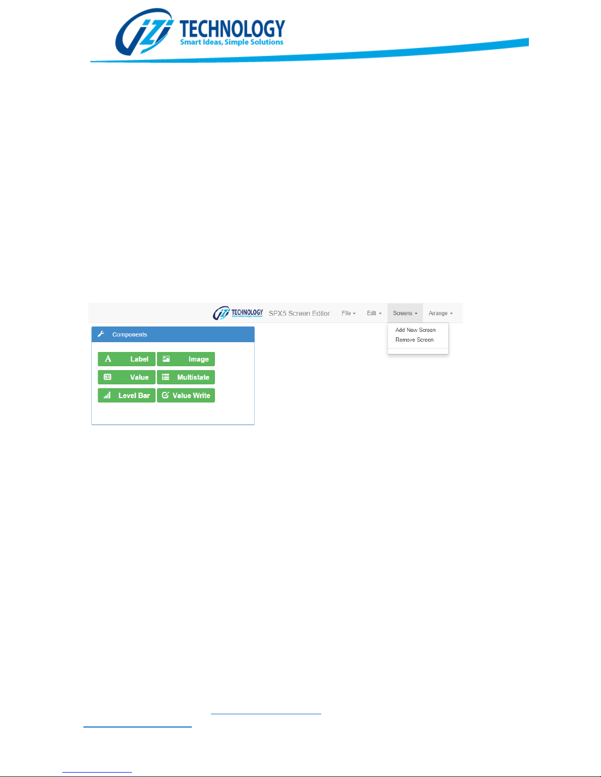
To create an HMI Screen, the user must go to the Screens menu and select “Add New Screen”. In
the screen properties, the user is able to select the dimensions as well as the background color.
Figure 31 shows the HMI Editor screen.
Once a new screen is created, it is possible to drag components to the screen. Dragging the
component with the mouse or moving it with the keyboard cursor keys can change the position of
the component. Also editing the coordinates in the properties window is allowed.
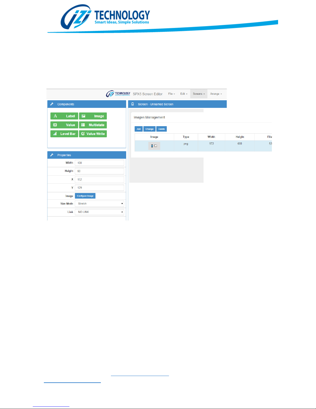
When dealing with images, an image has to be dragged into the screen and then change the image
on the Images Management Window that is accessed by clicking the Configure Image button as
shown in figure 32. It is important to know that everything that is done on the HMI Screens Editor
ends up in the configuration file. If large images are added, the configuration file will grow
correspondingly.
Most of the components have a Link property that allows configuring If clicking on the component
will take the user to a different screen.
IZI Technology Inc, 3651 Pegasus Dr. Ste. 117 Bakersfield, CA 93308 USA.
Tel: (661) 412-3494 -- email: [email protected]
www.izitechnology.com
Page 32
Figure
32.
Images Management Window
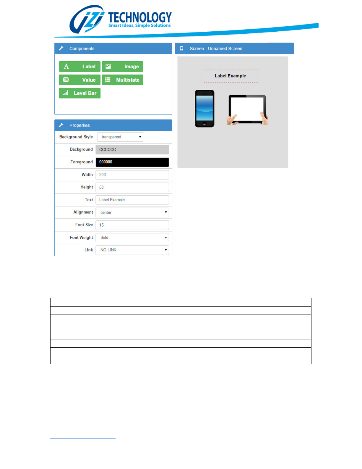
Figure 33 shows an example of a Screen that contains a Label with the text “Label Example” in the
properties window it can be seen all the possible option that can be changed on the label.
Value, Multistate Values and Level Bars have most of the same properties as the other components,
but they also have a Data Source property. This data source property allows setting the origin of the
information that will be shown on the component.
IZI Technology Inc, 3651 Pegasus Dr. Ste. 117 Bakersfield, CA 93308 USA.
Tel: (661) 412-3494 -- email: [email protected]
www.izitechnology.com
Page 33
Figure
33. Properties that can be configured in a Label Component
.
@UINT8(
Direction
in
Byte)
@UINT16(
Direction
in
Word[,swap code])
@INT16(
Direction
in
Word[,swap code])
@UINT32(
Direction
in
Word[,swap code])
@INT32(
Direction
in
Word[,swap code])
@REAL32(
Direction
in
Word[,swap code])
@BIT(
Direction
in
Bits)
Table
2.
Function allowed in the Data Source Property
.
Table 2 shows all the possible functions to bring data from the SPX5 database to the components
that have the Data Source Property.
Values allow setting a Prefix and Suffix to the value. This is really useful to show units and value
labels, without requiring to create multiple Label components for this.
The Multistate component allows configuring different strings or images to different database
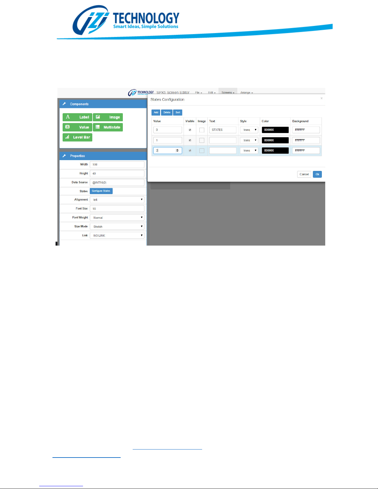
values. Figure 34 shows the multistate configuration window. When the Data Source takes one of
IZI Technology Inc, 3651 Pegasus Dr. Ste. 117 Bakersfield, CA 93308 USA.
Tel: (661) 412-3494 -- email: [email protected]
www.izitechnology.com
Page 34
Figure
34.
Multistate configuration window
.
the values show on Value, the configured text or image will be shown with the selected Foreground
and Background colors.
The Level Bar component allows changing the width or height according to a value in the database
specified by the Data Source Property. It is possible to choose the ranges of the variable as well as
the colors to be shown and the growing direction.
IZI Technology Inc, 3651 Pegasus Dr. Ste. 117 Bakersfield, CA 93308 USA.
Tel: (661) 412-3494 -- email: [email protected]
www.izitechnology.com
Page 35

Appendix.
IZI Technology Inc, 3651 Pegasus Dr. Ste. 117 Bakersfield, CA 93308 USA.
Tel: (661) 412-3494 -- email: [email protected]
www.izitechnology.com
 Loading...