

Page 1
A
B
C
D
E
F
G
I
H
J
ACB
D
TM 3050-RF
Opera tion an d displ ay General function
This ene rgy-saving controlle r for radiators can b e used to control room temp erature on the ba sis of time. The actu ator moves
a va lve, th ereb y allo wing t he amo unt o f heat flowin g to th e heat ing appliance to be controlled. The controller is compatible with
all standard heating appliance valves. The large illuminated
display ensures user-friendly ope ration. A wirele ss rece iver allows the devic e to receive commands from t aught-in syst em
components.
Insta llati on can be ac hieved in 3 easy st eps.
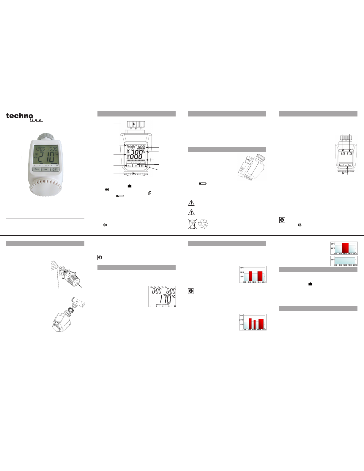
Step 1: Ins erti ng (repl acing) the bat teries
Remove the bat tery compartm ent cover.•
Insert 2 new LR6 batteries (Mignon/•
A A ) i n t o t h e b a t t e r y c o m p a r t m e n t , e n suring they a re the right way round.
Reattach the batter y compar tment •
cover and cli ck into place.
New alkaline batteries have a life of
approxima tely two year s. A batter y
symbol (
) will i ndicate whe n the batte ries need t o be replac ed. Aft er remov ing the o ld batte ries, p lease w ait appr oxima te ly 1 mi nu te b ef ore in se rt in g th e n ew o ne s. Thi s d ev ic e do es
not suppor t operation with rec hargeab le batteri es.
Never recha rge standard batte ries.
Doing so will p resent a risk of explosi on.
Do not throw the b atterie s into a fire.
Do not shor t-circui t batterie s.
Us ed bat te ri es s ho uld no t be di spo se d of wi th
regular domestic waste. Instead, they should
be taken to your l ocal batte ry disposal point .
Step 3: I nstal ling th e energy -savin g contro ller
The actuato r can be in stall ed on all standa rd he ating
valves. There is n o need to drain away w ater or fid dle
around with the heating system before doing this . Fir st,
you need to rem ove the old thermostat di al:
Turn the thermosta t di al a nti- •
clockwi se as far as it will go (A).
Release the therma l ring of the •
thermos tat (B).
Remove the thermostat from •
the valve (C).
An a dapter will need to be us ed in
the case of certai n valves. Adapters
for Danfoss valves (R A, RAV, RAVL) are included in the scope of
deliver y. For det ails, please refer to
the adapter ove rview (see 21).
The adapte r must be plac ed on •
the valve and tu rned until i t is securely sea ted.
In the case of th e RAV adapter, •
the extensi on supplied must be
attache d to the valve tappet.
The RA and R AV adapters must, •
in addition , be secure d by means
of the bolt an d nut supplie d.
The energy-saving controller can
only be inst alled if “InS” is showing on the display. Following ins tallation, the actuator will per form an adju stment run so
that it can adapt to the valve . D uring this proc ess, “AdA” w ill
be displaye d.
Place the act uator on the val ve.•
Tighten the u nion nut.•
“InS” will ap pear on the di splay, press the O K button.•
The actuator will perform an adjustment run (“AdA” will appear •
on the displa y, operation not p ossible).
After that , the actuator w ill be ready fo r operation ( Auto •
mode).
If the adjustment ru n was initiated prior to insta llation, or if
an erro r messag e will be displayed (F1, F2, F3); press OK
to move the motor ba ck to the “InS” po sition.
1. Setti ng the weekly pr ogram
The weekly program al lows yo u to set up to 3 separate
heating periods (7 switc hing times) for each day of the
week. Programming is p erform ed in relati on to the selected days , for which tempe ratures must be stored fo r a
period fr om 00:00 to 23:59.
Press and hold down the menu but-•
ton for more th an 3 seconds .
“Pro” will app ear on the dis play.•
Confirm wit h OK.•
“dAy” will appear on the display. The •
setting wheel can be used to select
an individual day of the week, all
working days, the weeke nd or the entire week (example
shows worki ng days selec ted).
Confirm wit h OK.•
Use the set ting wheel to set the first time segment (ex-•
ample shows 0 :00 to 6:00).
Confirm wit h OK.•
Then, s elect t he requi red temp erature for the selected •
time segme nt (example sh ows 17.0°C).
Confirm wit h OK.•
Keep repeating this process until you have finished storing •
temperat ures for the pe riod from 0:00 to 23:59.
In Auto mode, the temperature can be modified at any time
via the set ting wheel. The modifi ed temper ature will th en
be retaine d until the next program c hangeover.
2. Week ly progr am: Examples
The en ergy-savi ng contr oller a llows you to store up to 3
heating periods (7 switching times) with individual temperature set tings for each day of the week. The factor y setting con sists of two heati ng phase s (from 6:00 unti l 9:00
and f rom 17:00 until 23:00 respe ctively) for every single
day of the week:
From 00:00 to 06:00 17.0°C
From 06:00 to 09:00 21.0°C
From 09:00 to 17:00 17.0°C
From 17:00 to 23:00 21.0°C
From 23:00 to 23:59 17.0°C
To represent the switching periods, the display shows
bars for ever y other switching inter val. In this example, no bars are sh own for the interval from 0:0 0 to
6:00. Bar s are only show n on the display for the in-
tervals f rom 6:00 to 9:00 a nd from 17:00 to 23:00.
If a room also needs to be heated at around noon, the correspondi ng progra m might look like t his:
Monday to Sunday
From 00:00 to 06:00 16.0°C
From 06:00 to 09:00 22.0°C
From 09:00 to 12:00 17.0°C
From 12:00 to 14:00 20.0°C
From 14:00 to 17:30 17.0°C
From 17:30 to 23:30 21.0°C
From 23:30 to 23:59 16.0°C
If you have a hom e office a nd onl y want it to be heate d
during the day on working days , you can program the following time s:
Monday to Friday
From 00:00 to 08:30 17.0°C
From 08:30 to 17:00 21.0°C
From 17:00 to 23:59 17.0°C
Saturday and Sunday
From 00:00 to 23:59 15.0°C
3. Oper ating modes
To switch between t he 3 operati ng modes des cribed below, press the menu button briefly (these operating modes
can only be s elected fol lowing inst allation /Step 3):
Holida y function• (
): Set a tempe rature that is to be
maintain ed until a fixed p oint in time.
Manu: • Manual operation – The temperatur e is set manu-
ally using t he setting w heel.
Auto: • Weekly program – T he temperature is c ontrol-
led automat ically in acc ordance wit h the stored week ly
program.
4. Config uration men u
The configuration menu can be used to modify settings. To
access this menu, press and hold down the menu button
(for more than 3 seconds).
Pro: For setting the weekly program (see Section “1 Set-•
ting the week ly progra m”)
dAt: For modif ying the time of day and date•
POS: For quer ying the actuator’s curre nt position•
dSt: Automatic switchove r at the start or end of daylight •
saving time c an be deacti vated.
AEr: For se tting the “ window open” temperature and •
time s o that the temper ature is au tomatical ly red uced
in the event of ven tilation
tOF: For setti ng the offs et tempera ture•
rES: For restor ing the facto ry setti ngs•
Please read this manual ca refully in order to help you put the
device into operation. Keep the manual handy so you can refer
to it at a later date !
A Thermal r ing
B Day of the week
C Holiday function (
), set-back/comfo rt temperature
(
), m an ua l op er at ion (Manu), automatic operation
(Auto), “ win do w op en “ sy mb ol (
), “battery empty“
symbol (
)
D Menu button: Press and hold down the button for more
than 3 seco nds to open the c onfigurati on menu
E Setti ng wheel: For making adjus tments (e.g . tempe-
rature)
F Time a nd date indicator, menu items , function s
G Current temperat ure settin g
H Switching perio ds set within weekly pro gram
I OK button: For confirm ing/saving , teaching in
J
-b ut ton : Fo r s wi tch in g be tw ee n se t-b ac k a nd c om -
fort temp eratures
5
2
6
3
7
4
8
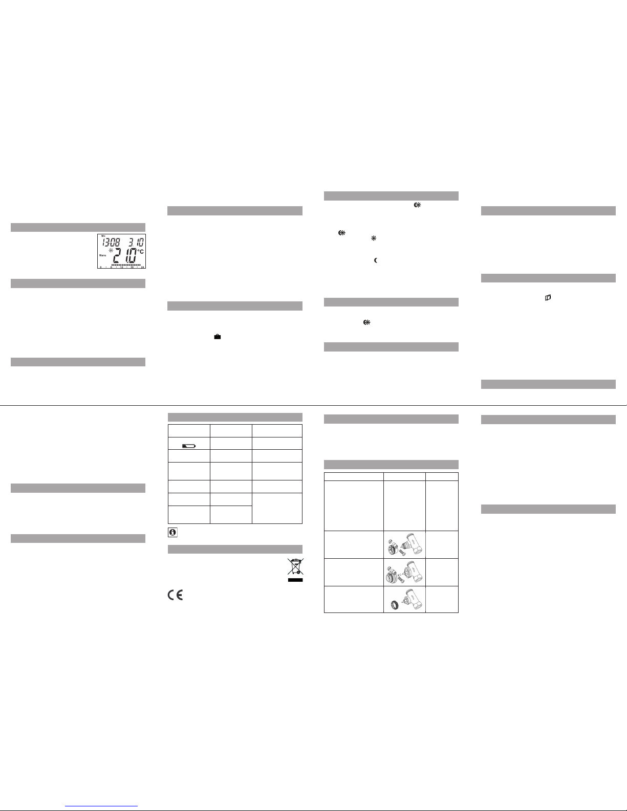
Step 2: S etting the da te and time of day
The firmwar e version nu mber will be d isplayed br iefly once yo u
have inser ted/replaced the b atteries and then you will be auto maticall y prompted to se t the date and tim e of day.
Use the set ting wheel (C) •
to set the year ( B).
Confirm wit h OK (D).•
Use the set ting wheel (C) •
to set the month ( B).
Confirm wit h OK (D).•
Use the set ting wheel (C) •
to set the day (B).
Confirm wit h OK (D).•
Use the set ting wheel (C) •
to set the hour ( A).
Confirm wit h OK (D).•
Use the set ting wheel (C) •
to set the minut e (A).
Confirm wit h OK (D).•
The motor wil l start mov ing back the
control pi n while the entr ies are still being mad e.
If “InS” is displayed with a rotating “∏” symbol, this indi-•
cates that the motor is still moving back. Once the device
is ready for the actuator to be installed on the valve, just
“InS” will ap pear on the di splay.
The weekl y program and oth er setti ngs can be cus-•
tomised prior to installation. To do this, press the menu
button w hen “InS ” is show n on the display. For furthe r
details, p lease see “4. Confi guration m enu”.
Once prog ramming is c omplete, “In S” will reapp ear •
on the displa y and instal lation (Step 3) c an commence.
When “InS” is v isible on the di splay, you can activ ate the teach -in functi on prior to installa tion by pres sing the
button br iefly.
Page 2
UnL: For teach ing out all ta ught-in wirel ess compo nents •
Use the setting wheel to select menu items and the OK button to confirm your choice. Press the menu button again to
return to the previous level. After 65 seconds without anything happening, the menu will close automatically.
5. Disp lay content dur ing normal ope ratio n
During normal operation, the following
ar e di sp la yed : da y o f th e we ek , t ime of
day, date, operating mode, temperature setti ng and switchi ng period s.
The bars in dicating the we ekly pro gram’s switching periods are shown
for every other time interval. For an example, ple ase refer to “2. We ekly progr am: Examples”.
6. Teachin g in wirel ess componen ts
The ac tuator suppo rts t he teaching in of up to 4 system
compone nts (e.g. remote control and wi ndow contact),
plus 1 wall the rmostat.
Press and ho ld down the OK button for mo re than 3 seconds.•
The remai ning teach- in time will be di splayed (30 se conds).•
The device being taught-in now needs to send a wireless •
signal (e.g. pr ess butto n on remote con trol).
The display w ill then switch to the norma l view.•
On ce t his ha s be en d on e, t he a ctu ato r w ill res po nd t o wi reless comm ands from taught-in devic es. Whenever the actuator re ceives a signa l from a window contact or r emote
control, th e display will li ght up briefly.
7. Teaching out wi reless compo nents
Componen ts that have been taught in on the actuator can be
ta ug ht o ut aga in usi ng the “U nL” ( Unl ea rn ) fu nc tio n. All wi re less comp onents are t aught out at once with thi s function.
Press and ho ld down the menu button for m ore than 3 seconds.•
Use the set ting wheel to s elect the “U nL” menu item.•
Confirm wit h OK.•
“ACC” will appear o n the display; p ress OK to confirm.•
8. Oper ation with a wal l therm ostat
If the actuator is goi ng to be operated in con junction wit h a wall
thermos tat, this thermostat will need to be taught in (see 6). Once
it has be en tau gh t in , “ ECF ” wi ll app ea r on th e di sp lay . No fu rth er
settings can then be made on the actuator and it will no longer
respond to t aught-in rem ote controls o r window cont acts.
If no wir eless si gnal is r eceived from the wall ther mostat
for a period of 60 minutes, the actuator will exit ECF mode.
It will then assume control of the temperature, which it will
continue to regulate in accordance wi th the weekly program until th e next wirel ess signa l is received .
To “ te ach ou t” a wa ll t he rmo st at , yo u mu st rei ns er t th e b atteries in the act uator (and wait for app rox. 1 minute). Once
you have entered the date and time of day, you can use the
men u but ton (b efore the ad justm ent ru n is in itiat ed) to perform the “te ach-out” proces s as described in sec tion 7.
9. Sett ing the holida y funct ion
If you want a fixed tempera ture to be maintain ed for a set
period of time while yo u are on hol iday or dur ing a par ty,
you can make us e of the Holiday f unction.
Press and re lease the me nu button re peatedly un til the •
suitcase sy mbol (
) appears on the disp lay.
Use the se tting wh eel to set the end of the time period •
during whi ch the temper ature is to be maintaine d.
Press the OK b utton to confi rm.•
Then use th e setting wh eel to set the da te.•
Press the OK b utton to confi rm.•
Use the setting wheel to set the temperatu re; press OK to •
confirm. Th e display will fl ash to confir m your settin gs.
The s et tem perature will remai n in force until the specified t ime. A fter that, the actuator will adopt Auto mode.
Wireless comma nds from the window contact and remote
control wil l continue to b e executed.
10. Comfor t and set-back te mperature s
The comfort/set-back temperature button (
) pr ov id es a n e asy
and con venient way of sw itching b etween these two temperatures. The fac tory setting s are 21.0°C and 17.0°C resp ectively.
To adapt them, proc eed as follows:
Press and hold down the comfort/set-back temperature but-•
ton (
) for more than 3 second s.
The sun symbol ( • ) will a ppear on the display along
with the cur rent comfor t temperature.
Use the settin g wheel to modif y the temperatu re; press •
OK to confirm.
The moon symbo l ( •
) will appear tog ether with the setback tempe rature.
Use the settin g wheel to modif y the temperatu re; press •
OK to confirm.
The temperature can even be modified in Auto mode at any
time by using this button. The new settin g will be retained
until the pro gram’s next switc hing time.
11. Child-proof lock/Operating inhibit
Operati on can be inhib ited.
To activate/deac tivate the operating inhibit, briefly press •
the Menu and
buttons at t he same time.
Once the functi on is active, “LOC” will appear on the •
display.
To deactivate the fu nction, pre ss both but tons again.•
12. Set ting th e heati ng break
If the heating is being switc hed o ff fo r the summ er, you
can save battery p ower. This involves opening the valve
up fully. Lim escale p rotection measure s remain i n place.
Wireles s comman ds from t he window contact or remote
control wil l no longer be e xecuted.
To ac tivate the heating break, turn the setting wheel •
clockwi se during manual operatio n ( Manu) un til “On”
appear s on the display.
To terminate the heating break, quit manual ope ration •
(Manu) or turn the se tting whe el anticlo ckwise.
13. Sett ing frost prot ectio n mode
If you do not want the room to be hea ted, the valve can
be closed. It will only be o pened aga in if there is a r isk of
freezing due to fro st. Limes cale pro tection me asures remain in place. Wireles s commands from the window con tact or rem ote control wi ll no longer b e executed.
To activate frost protecti on mode, turn the setting wheel •
anticlockwise during manual operation (Manu) until “OFF”
appear s on the display.
To terminate frost prote ction mode, quit manual oper a-•
tion (Manu) or turn t he setting w heel clock wise.
14. “Wind ow open” functi on
If t he ro om i s bei ng ve ntil ated , the act uato r con tro ls th e tem perature to save on heating costs. While this function is active,
the “window o pen” symbol (
) appears on the disp lay.
Wi th ou t w in do w co nt ac t: Th e ac tu at or w il l au to ma tic al ly de tect a signifi cant drop in temp erature due to ve ntilation. You
can set your ow n “window ope n” temperatu re and time.
With taug ht-in window contact: T he t em pe rat ur e w ill on ly
be re duc ed du ri ng t he tim e t hat th e wi nd ow i s l ef t o pen . Yo u
can set your ow n “window ope n” temperatu re.
Press and hol d d own the menu butto n f or more than •
3 seconds .
Use the set ting wheel to s elect the “AEr” m enu item.•
Confirm wit h OK.•
Use the setting wheel to set the temperature/t ime. Then •
press OK to co nfirm.
Without a taught-in window contac t, this function c an •
be deactiva ted by selec ting a time of “0”.
15. Sett ing the offse t tempe ratur e
The temper ature is meas ured at the heat ing applian ce it-
self, wi th the result that other par ts of the room m ay be
warmer o r colder than this. To allow for this, you can set
a temperatu re offset of ±3.5°C. If, for example, a te mperature of 18°C is meas ured somewhere within th e r oom
instead o f the 20°C s et, it means that an offset of -2.0°C
needs to be c onfigured.
Press and hol d d own the menu butto n f or more than •
3 seconds .
Use the set ting wheel to s elect the “ tOF” menu item.•
Confirm wit h OK.•
Use the set ting wheel to m odify the te mperatur e.•
Press the OK b utton to confi rm.•
16. Resto ring th e factor y settings
You can reset the actuator to its initial state manually. This
will clear a ll the setti ngs that have be en made manu ally.
Press and hol d d own the menu butto n f or more than •
3 seconds .
Use the set ting wheel to s elect the “r ES” menu item.•
Confirm wit h OK.•
“ACC” will appear o n the display; p ress OK to confirm.•
17. Intended us e
The e nergy-sav ing co ntroller has been desig ned f or the
purpose of controlling a standard heating appliance valve.
The device may only be operated indoors an d mu st b e
protected from the ef fects of damp and dust, a s well a s
solar radi ation and so urces of rad iant heat.
Using the dev ice for a purpose or in a manner oth er than
that desc ribe d in th is operati ng ma nual constitu tes a
breach of the “inten ded use” and shall invali date the warranty and a ny liabilit y claims. Th e same shall ap ply in the
event of any c onversion or modification work. The devices
are intende d exclusively for domest ic use.
18. Trouble shoot ing and ma intenance
Error c ode on
display
Problem Remedy
Battery symbol
(
)
Batter y power
too low
Replace batteries
F1
Valve actuator
sluggish
Check inst allation, in-
spect hea ting valve
F2
Adjusting r ange
too large
Check
actuator
fastening
F3
Adjusting r ange
too small
Check heat ing valve
F4
1 wall therm ostat
already ta ught in
Teach out device s
F5
4 wireles s components a lready
taught in
At 12:00 every Saturday, the ac tuator perfo rms a weekly
descalin g fun ction to prevent valve calcification. “CAL” will
appear on t he display.
19. Instr uctions for di sposal
Do not dis pose of the devic e with regula r
domestic waste.
El ect ron ic e quip men t mu st b e di spo sed of at loc al c ollection points fo r waste e lectroni c equipme nt in compliance with loca l di rectives gover ning waste electri cal
and elect ronic equip ment.
Th e C E si gn i s a fre e t ra de s ig n ad dr es se d ex clu si vel y t o
the author ities and do es not warra nt any prope rties.
22. In format ion about radi o operation
Radio transmis sion is performed on a non-exclusive trans mission path, which means that there is a possibility of interfere nce occur ring.
Switching oper ations, electr ic motors or faulty electric device s
ar e so me of t he rea so ns why int er fe re nce ma y oc cu r. T he r an ge
of transmis sion within build ings can deviate gre atly from open
ai r di st an ce s. B es ide s t he t ra ns mit ti ng pow er a nd th e re ce pti on
characte ristics of the receiver, environment al infl uences such as
humidity a nd local structure s also play an im porta nt role.
TechnoTrade Impor t-Expor t GmbH hereb y decla res that
this device confo rms with the essenti al requirem ents and
other releva nt regulat ions of Dire ctive 1999/5/EC.
The full dec laration of conformi ty is provid ed at
www.technoline-berlin.de/Konformitaetserklaerung.
23. Technical properties
Supply volt age: 3 V
Max. cur rent consu mption: 100 mA
Batteries: 2x LR6 batteries (Mignon/AA)
Batter y life: Approx. 2 yea rs
Display: LC display
Receiver f requency : 868.3 MHz
Housing di mensions: 63 x 76 x 102 mm (W x H x D)
Ambient te mperatur e: +5 to +55°C
Max. sur face temperature: +90°C (of r adiator)
Linear tra vel: 4.2 mm
Spring for ce: max. 80 N
Connect ion: M30 x 1.5
We reser ve the right to mak e any tech nical c hanges t hat
const itute a n improve ment to the devic e.
Issue 1 Eng lish 10/2009
Documen tation © 2009 TechnoTrade Impo rt-Export G mbH, Wildau.
All right s reserved.
CC-RT-RX- CyE-W-R3, V1.1 907-76
9
13
10
14
11
15
12
16
20. Saf ety ins tructions
Th e d evi ce s c onc er ne d a re n ot int en de d fo r c hi ldr en an d mu st no t
be used as toys. Do not le ave packagin g material l ying arou nd,
as childre n might be tempt ed to play with it, w hich is extre mely
da ng ero us . D o no t op en th e de vi ce: it d oe s n ot c on ta in a ny c om ponents th at need to be ser viced by the user. In the event of an
error, pleas e return the dev ice to our ser vice departmen t.
21. Adapte r overview
Manufacturer Figure Adapter
Heimeier, MNG , Jun-
kers, Lan dis&Gyr
“Duodyr ”, Honeywell-
Braukma nn, Oventrop,
Schlöss er, Simplex,
Valf Sanayii, M ertik
Maxitro l, Watts,
Wingenro th (Wirofle x),
R.B.M., Tie mme, Jaga
No adapter
required
Danfoss R A
Included
in scope of
supply
Danfoss R AV
Included
in scope of
supply
Danfoss R AV L
Included
in scope of
supply
 Loading...