

Page 1
User Manual
VICTUS™ Femtosecond Laser Platform, SW V3.3 SP02
UM-100010770 GB
SKU: 70005780TPV
Version 6
Page 2

Publishing details
User Manual
Version 6
[VICTUS SW V3.3 SP02; PI 125 Kit (REF 90000115) or PI 125 Kit (REF 90000145)]
Manufacturer
Technolas Perfect Vision GmbH
Messerschmittstr. 1 + 3
80992 München
Germany
www.TechnolasPV.com
For Customer Service or Technical Support:
Contact your local Customer Service or Technical Support.
Copyright
This document is protected by copyright. All rights reserved. Notably, no portion of this publication may be reproduced or made
available to third parties, in any form, online or offline, without the written consent of Technolas Perfect Vision GmbH. Further, no
portion of this publication may be translated into a language or code that can be utilized for machines, in particular, data processing
systems, or the internet. This document may exclusively be used to properly use the products described herein in accordance with
the contractual terms for such product.
Copyright © 2017 Technolas Perfect Vision GmbH
Subject to technical changes.
Document no. UM-100010770 GB
Edition: 2017-06-12
Page 3

A General information
A.1
Information about this user manual......................................................................................... A - 1
A.2 Explanation of symbols................................................................................................................... A - 1
A.3 Customer service................................................................................................................................ A - 2
A.4 Product names used in this user manual................................................................................ A - 3
A.5 Reference documents to this user manual............................................................................. A - 3
1 Introduction
1.1 VICTUS™ Femtosecond Laser Platform.................................................................................... 1 - 1
1.2 Scope of delivery................................................................................................................................. 1 - 1
1.3 Use with other medical devices.................................................................................................... 1 - 2
1.4 List of abbreviations.......................................................................................................................... 1 - 2
1.5 Definitions.............................................................................................................................................. 1 - 3
2 Safety
2.1 Intended use.......................................................................................................................................... 2 - 1
2.2 Complications (side effects)........................................................................................................... 2 - 1
2.3 Important safety considerations................................................................................................. 2 - 3
2.4 Responsible organization............................................................................................................... 2 - 3
2.5 Customer responsibilities............................................................................................................... 2 - 4
2.6 Personnel requirements.................................................................................................................. 2 - 4
2.6.1 Role definitions....................................................................................................................................... 2 - 4
2.7 General hazards................................................................................................................................... 2 - 5
2.7.1 Electrical hazard...................................................................................................................................... 2 - 6
2.7.2 Laser radiation hazard.......................................................................................................................... 2 - 7
2.7.3 Fire hazard................................................................................................................................................ 2 - 7
2.7.4 Mechanical hazard................................................................................................................................. 2 - 8
2.7.5 Damage to property............................................................................................................................. 2 - 8
2.8 Warning signals and alarms........................................................................................................... 2 - 9
2.9 Safety devices....................................................................................................................................... 2 - 9
TABLE OF CONTENTS
SKU: 70005780TPV * Version 6 * UM-100010770 GB
1
Page 4

2.10 Labeling................................................................................................................................................ 2 - 11
2.10.1
Labels in the operating room entrance area............................................................................. 2 - 12
2.10.2 Labels on the laser system............................................................................................................... 2 - 13
3 Transport and storage
3.1 Transportation..................................................................................................................................... 3 - 1
3.2 Visual inspection after delivery................................................................................................... 3 - 1
3.3 Storage before installation............................................................................................................ 3 - 2
3.4 Unpacking............................................................................................................................................... 3 - 2
4 Installation, commissioning, service, calibration,
decomissioning and disposal
4.1 Installation and comissioning....................................................................................................... 4 - 1
4.1.1 Interface of the patient beds "LS Comfort" and "Patient Support System S60" by
AKRUS GmbH & Co KG......................................................................................................................... 4 - 2
4.2 Service and calibration..................................................................................................................... 4 - 3
4.3 Decomissioning and disposal....................................................................................................... 4 - 3
5 Clinical applications
5.1 Medical indications............................................................................................................................ 5 - 1
5.2 Patient selection criteria.................................................................................................................. 5 - 2
5.2.1 Contraindications................................................................................................................................... 5 - 2
5.3 Available procedures........................................................................................................................ 5 - 3
5.3.1 Cataract procedures.............................................................................................................................. 5 - 3
5.3.2 Corneal procedures............................................................................................................................... 5 - 4
5.3.3 Therapeutic procedures...................................................................................................................... 5 - 4
6 Hardware
6.1 Overview on the components....................................................................................................... 6 - 1
6.2 Operating the hardware.................................................................................................................. 6 - 2
6.2.1 Main unit................................................................................................................................................... 6 - 2
TABLE OF CONTENTS
SKU: 70005780TPV * Version 6 * UM-100010770 GB
2
Page 5

6.2.2 Assistant workstation / surgeon control screen......................................................................... 6 - 3
6.2.2.1
Adjusting the monitor settings......................................................................................................... 6 - 3
6.2.3 Start-up panel.......................................................................................................................................... 6 - 4
6.2.3.1 Switching the laser system on and off........................................................................................... 6 - 4
6.2.4 Suction status controller..................................................................................................................... 6 - 5
6.2.4.1 Adjusting the suction status.............................................................................................................. 6 - 5
6.2.5 Force display............................................................................................................................................ 6 - 6
6.2.6 Laser ring light illumination switch................................................................................................. 6 - 6
6.2.6.1 Switching the laser ring light illumination on and off.............................................................. 6 - 7
6.2.7 Camera focus switch............................................................................................................................. 6 - 7
6.2.7.1 Adjusting the camera focus............................................................................................................... 6 - 7
6.2.8 Spacer cone.............................................................................................................................................. 6 - 7
6.2.8.1 Protecting the spacer cone................................................................................................................ 6 - 8
6.2.9 Surgical microscope and its illumination...................................................................................... 6 - 8
6.2.9.1 Adjusting the surgical microscope illumination...................................................................... 6 - 10
6.2.10 Footswitches......................................................................................................................................... 6 - 11
6.2.11 Patient bed............................................................................................................................................. 6 - 12
6.2.11.1 Referencing the patient bed........................................................................................................... 6 - 12
6.3 Cleaning instructions..................................................................................................................... 6 - 13
7 Accessories and tools
7.1 Accessories............................................................................................................................................. 7 - 1
7.2 Tools.......................................................................................................................................................... 7 - 2
8 Software
8.1 Working with the software............................................................................................................. 8 - 1
8.1.1 Starting and closing the software.................................................................................................... 8 - 1
8.1.2 Elements of the ‘Main menu’ screen............................................................................................. 8 - 5
8.1.3 Elements of the treatment screens.................................................................................................. 8 - 6
8.1.3.1 Treatment-specific elements........................................................................................................... 8 - 11
8.1.4 Checking and modifying common settings.............................................................................. 8 - 17
8.1.5 Checking treatment licenses........................................................................................................... 8 - 18
8.1.6 Restarting the software after an emergency shutdown....................................................... 8 - 18
8.2 User administration........................................................................................................................ 8 - 19
TABLE OF CONTENTS
SKU: 70005780TPV * Version 6 * UM-100010770 GB
3
Page 6

8.2.1 User profiles and specific rights..................................................................................................... 8 - 19
8.2.2
Adding users......................................................................................................................................... 8 - 20
8.2.3 Editing registered user accounts................................................................................................... 8 - 21
8.3 System test description................................................................................................................. 8 - 21
8.4 Patient / treatment administration......................................................................................... 8 - 23
8.4.1 Adding patients................................................................................................................................... 8 - 24
8.4.2 Selecting patients................................................................................................................................ 8 - 25
8.4.3 Editing patient data............................................................................................................................ 8 - 26
8.4.4 Deleting patient data......................................................................................................................... 8 - 26
8.4.5 Selecting treatments for execution.............................................................................................. 8 - 27
8.4.6 Creating treatments........................................................................................................................... 8 - 28
8.4.6.1 Creating treatments based on default values........................................................................... 8 - 30
8.4.6.2 Creating treatments based on a template................................................................................. 8 - 31
8.4.7 Editing treatments.............................................................................................................................. 8 - 32
8.4.8 Deleting treatments........................................................................................................................... 8 - 32
8.4.9 Deleting treatment templates........................................................................................................ 8 - 33
8.4.10 Treatment records............................................................................................................................... 8 - 33
8.5 Procedure parameters................................................................................................................... 8 - 34
8.5.1 Parameters for capsulotomy........................................................................................................... 8 - 36
8.5.2 Parameters for lens fragmentation............................................................................................... 8 - 37
8.5.3
Parameters for arcuate incisions.................................................................................................... 8 - 40
8.5.4 Parameters for corneal incisions.................................................................................................... 8 - 43
8.5.4.1 Schematic overview on corneal incisions................................................................................... 8 - 46
8.5.5 Parameters for flap.............................................................................................................................. 8 - 48
8.5.6 Parameters for penetrating keratoplasty.................................................................................... 8 - 50
8.5.7 Parameters for lamellar keratoplasty........................................................................................... 8 - 51
8.5.8 Parameters for crosslinking............................................................................................................. 8 - 53
8.5.9 Parameters for ICRS tunnel.............................................................................................................. 8 - 54
8.5.9.1 Schematic overview on ICRS tunnel incisions........................................................................... 8 - 59
9 Treatment
9.1 Preparing the laser system for a treatment day.................................................................. 9 - 1
9.2 Maintaining the laser system after a treatment day......................................................... 9 - 1
9.3 Performing the daily system test................................................................................................ 9 - 2
TABLE OF CONTENTS
SKU: 70005780TPV * Version 6 * UM-100010770 GB
4
Page 7

9.3.1 Chiller submenu..................................................................................................................................... 9 - 2
9.3.2
Performing the laser position test................................................................................................... 9 - 3
9.3.3 Performing the vacuum test.............................................................................................................. 9 - 4
9.3.4 Performing the pressure test............................................................................................................. 9 - 5
9.3.5 Performing the power test................................................................................................................. 9 - 6
9.3.6 Performing the depth test.................................................................................................................. 9 - 7
9.4 Daily routine.......................................................................................................................................... 9 - 8
9.4.1 When performing a treatment.......................................................................................................... 9 - 8
9.4.2 Positioning the patient on the patient bed.................................................................................. 9 - 9
9.4.2.1 Using a headrest with integrated joystick.................................................................................. 9 - 10
9.4.2.2 Using a headrest with external joysticks..................................................................................... 9 - 11
9.4.3 Connecting the PI 125 to the spacer cone and positioning the suction clip................. 9 - 11
9.4.3.1 Connecting the PI 125 (REF 90000115) to the spacer cone and positioning the suction
clip (REF 90000115)............................................................................................................................. 9 - 13
9.4.3.2 Connecting the PI 125 (REF 90000145) to the spacer cone and positioning the suction
clip (REF 90000145)............................................................................................................................. 9 - 18
9.4.4 Docking the patient to the spacer cone...................................................................................... 9 - 22
9.4.4.1 For capsulotomy and lens fragmentation procedures using a headrest with inte‐
grated joystick...................................................................................................................................... 9 - 23
9.4.4.2 For capsulotomy and lens fragmentation procedures using a headrest with external
joysticks................................................................................................................................................... 9 - 25
9.4.4.3 For all other procedures using a headrest with integrated joystick................................. 9 - 26
9.4.4.4 For all other procedures using a headrest with external joysticks.................................... 9 - 27
9.4.5 Repositioning the suction clip........................................................................................................ 9 - 28
9.4.6 Completing a treatment................................................................................................................... 9 - 29
9.5 Performing a cataract treatment.............................................................................................. 9 - 30
9.5.1 Preparing a cataract treatment...................................................................................................... 9 - 30
9.5.2 Performing a cataract treatment supported by a 2S-OCT.................................................... 9 - 31
9.5.3 Performing a cataract treatment supported by a TD-OCT................................................... 9 - 44
9.6 Performing a corneal treatment............................................................................................... 9 - 51
9.6.1 Performing a flap procedure........................................................................................................... 9 - 51
9.7 Performing a therapeutic treatment...................................................................................... 9 - 55
10 Troubleshooting chart
11 Technical data
TABLE OF CONTENTS
SKU: 70005780TPV * Version 6 * UM-100010770 GB
5
Page 8

11.1 General specifications.................................................................................................................... 11 - 1
11.2
Operating conditions..................................................................................................................... 11 - 3
11.3 Laser specifications......................................................................................................................... 11 - 4
11.4 Transport and storage conditions............................................................................................ 11 - 4
11.5 Electrical connection....................................................................................................................... 11 - 4
12 Index
13 Appendix
TABLE OF CONTENTS
SKU: 70005780TPV * Version 6 * UM-100010770 GB
6
Page 9
A
General information
To order additional copies of this user manual:
If additional copies of this user manual are required, refer to the SKU number on the
cover page and contact your Authorized Technolas Perfect Vision Representative.
A.1
Information about this user manual
This user manual enables safe and efficient handling of the product, its accesso‐
ries and tools. It must be kept close to the product where it is permanently acces‐
sible to the personnel.
Before starting any treatments, the personnel must read the manual thoroughly
and understand its contents. Users must comply with all specified safety instruc‐
tions and operating instructions to ensure safe operation.
In addition, local accident prevention regulations and general safety instructions
must be observed in the area where the product is used.
The product images in this user manual are intended to provide a basic under‐
standing of the product and may differ from the actual design you have on site.
Screenshots were created using an exemplary patient and exemplary values.
Depending on your system’s configuration the depicted screenshots may not be
identical to the screen shown on your system.
The software user interface may only be available in English. Where applicable,
the Appendix section of the user manual contains a list of the English software
texts together with the appropriate translation.
A.2 Explanation of symbols
Safety notes in this user manual are introduced with symbols and a signal word
that describe the severity of the hazard.
Follow these safety notes and proceed with caution to avoid accidents, personal
injury, damage to property, and to ensure patient safety.
This symbol and the word "DANGER" indicate an imminent hazardous situa‐
tion that, if not avoided, could cause death or serious injury.
This symbol and the word "WARNING" indicate a possible hazardous situa‐
tion that, if not avoided, could cause death or serious injury.
This symbol and the word "CAUTION" indicate a possible hazardous situa‐
tion that, if not avoided, could result in minor or moderate injury.
This symbol and the word "NOTICE" indicate a possible hazardous situation
that, if not avoided, could result in damage to property or the environment.
Safety notes
L DANGER
L WARNING
L CAUTION
NOTICE
GENERAL INFORMATION
A
SKU: 70005780TPV * Version 6 * UM-100010770 GB
A - 1
Page 10
This symbol emphasizes useful tips and recommendations as well as information for
the efficient and trouble-free use of the product.
This field shows examples of previous instructions or information.Example of ...
Safety notes are included in step-by-step instructions. This format allows the user
to be aware of safety issues while performing tasks. The safety symbols are also
part of the step-by-step instructions.
The following symbols and markings are used in this manual to indicate guide‐
lines, descriptions of results, lists, and references:
Symbol Indicates
Step-by-step instructions
ð
Condition or automatic sequence as a result of
action
References to chapters in this user manual
Lists or list entries without a certain sequence
[Ctrl] Keys on the keyboard, mouse buttons, key switches,
hardware switches, or hardware buttons
‘Start’ Active (clickable) GUI elements
‘Patient selection’ Passive elements
c:\Program\..
Text input
‘Administration
è User Registry’
Menu path
A.3 Customer service
Our customer service division is available to provide technical support and infor‐
mation. If any questions arise that are not answered in this user manual, do not
hesitate to contact your Authorized Technolas Perfect Vision Representative for
assistance.
Hints, recommendations,
and examples
Safety notes in step-by-step
instructions
Symbols in this user manual
GENERAL INFORMATION
A
SKU: 70005780TPV * Version 6 * UM-100010770 GB
A - 2
Page 11

A.4 Product names used in this user manual
For the sake of better readability and depending on the context, product names
may appear in abbreviated form.
Complete product name Name used in this user manual
Patient Interface 125 Kit in general PI 125 Kit
Patient Interface 125 Kit (REF 90000115) PI 125 Kit (REF 90000115)
Patient Interface 125 Kit (REF 90000145) PI 125 Kit (REF 90000145)
Patient Interface 125 in general PI 125
Patient Interface 125 (REF 90000115) PI 125 (REF 90000115)
Patient Interface 125 (REF 90000145) PI 125 (REF 90000145)
Suction Clip 125 in general suction clip
Suction Clip 125 (REF 90000115) suction clip (REF 90000115)
Suction Clip 125 (REF 90000145) suction clip (REF 90000145)
VICTUSä Femtosecond Laser Platform VICTUSä Femtosecond Laser
Platform
or generic term 'laser system'
A.5 Reference documents to this user manual
The following reference documents are related to this user manual.
Document number Document title
GFO-100012286 Product configuration for VICTUS™
Femtosecond Laser Platform
ADD-100011422 Addendum to the user manual
"VICTUSä Femtosecond Laser Plat‐
form, SW V3.3 SP02" (English)
GENERAL INFORMATION
A
SKU: 70005780TPV * Version 6 * UM-100010770 GB
A - 3
Page 12

GENERAL INFORMATION
A
SKU: 70005780TPV * Version 6 * UM-100010770 GB
A - 4
Page 13

1
Introduction
1.1
VICTUS™ Femtosecond Laser Platform
The VICTUS™ Femtosecond Laser Platform is an ophthalmologic system based on
femtosecond technology and is used to treat a wide variety of ophthalmologic
indications.
The following treatments are available:
The laser system is able to perform steps of a cataract treatment.
For this purpose, an additional OCT (optical coherence tomography) device is
available to help plan the procedure and monitor the treatment.
For details refer to
Ä
Chapter 5.3.1 ‘Cataract procedures’ on page 5 - 3.
The laser system allows very precise, preprogrammed, 3-dimensional patterns to
be cut into the cornea of the human eye. These patterns are cut using infrared
light pulses with spot sizes of approximately 10 μm and pulse duration of several
hundred femtoseconds. The infrared light is focused into the cornea and induces
optical breakdown or photodisruption with practically no heat. This results in the
formation of gas bubbles.
The user can arrange these patterns in various ways, so that various surgical inci‐
sions are possible, for example, a laser-generated LASIK flap.
For details refer to
Ä
Chapter 5.3.2 ‘Corneal procedures’ on page 5 - 4.
Furthermore, the laser system is able to perform various therapeutic treatments.
For details refer to
Ä
Chapter 5.3.3 ‘Therapeutic procedures’ on page 5 - 4.
1.2 Scope of delivery
n VICTUS™ Femtosecond Laser Platform
n User manual "VICTUS™ Femtosecond Laser Platform, SW V3.3 SP02"
n Addendum to the user manual "VICTUS™ Femtosecond Laser Platform,
SW V3.3 SP02" (English)
n Patient bed (delivered with 2 fuses)
n
–
User manual "Laser Patient Bed LS Comfort" by AKRUS GmbH & Co KG or
– User manual "Patient Support System PSS S60" by AKRUS GmbH & Co KG
n Accessories and tools (refer to
Ä
Chapter 7 ‘Accessories and tools’ on page 7 - 1)
– Plug adapter
Cataract treatments
Corneal treatments
Therapeutic treatments
INTRODUCTION
1
SKU: 70005780TPV * Version 6 * UM-100010770 GB
1 - 1
Page 14

Connect only items that have been specified as part of the
VICTUS™ Femtosecond Laser Platform ME system or specified as being com‐
patible with the VICTUS™ Femtosecond Laser Platform ME system!
The following items form the VICTUS™ Femtosecond Laser Platform ME
system:
– VICTUS™ Femtosecond Laser Platform
–
Patient bed with swivel position 16,5°, 60° or 70°
– Uninterruptible power supply (UPS): see relevant customer configura‐
tion sheet (transient currents up to 16 A possible)
The following parts of the VICTUS™ Femtosecond Laser Platform ME system are
suitable for use within the patient environment:
n VICTUS™ Femtosecond Laser Platform
n Patient bed with swivel position 16,5°, 60° or 70°
1.3 Use with other medical devices
Do not use VICTUS™ Femtosecond Laser Platform together with medical
devices other than the devices described in this section.
Patient beds "LS Comfort" and "Patient Support System S60" by AKRUS
GmbH & Co KG
These patient beds are medical devices that are approved in accordance with the
Medical
Device Directive. Technolas Perfect Vision GmbH has assessed their use in
combination with VICTUS™ Femtosecond Laser Platform. Technolas Perfect Vision
GmbH allows only specific versions of the "LS Comfort" or the "Patient Support
System S60" patient bed to be used with VICTUS™ Femtosecond Laser Platform. It
must be installed by an Authorized Service Technician. For information about
how to operate the patient bed refer to the user manual "Laser Patient Bed LS
Comfort" or "Patient Support System PSS S60" by AKRUS GmbH & Co KG. Refer to
Ä
Chapter 4.1.1 ‘Interface of the patient beds "LS Comfort" and "Patient Support
System S60" by AKRUS GmbH & Co KG’ on page 4 - 2 for the interface description.
1.4 List of abbreviations
ACD Anterior Chamber Depth
AI Arcuate Incisions
BSS Balanced Salt Solution
CXL Crosslinking
D Diopter
EHD Exit Height Difference
EMC Electromagnetic Compatibility
ME system
L WARNING
L WARNING
INTRODUCTION
1
SKU: 70005780TPV * Version 6 * UM-100010770 GB
1 - 2
Page 15

fs femtosecond
GUI Graphical User Interface
H0 Height Zero
hPa hecto Pascal
ICRS Intracorneal Ring Segments
LASER Light Amplification by Stimulated Emission of Radiation
LASIK Laser-Assisted In Situ Keratomileusis
LCD Liquid Crystal Display
LED Light-Emitting Diode
LKP Lamellar Keratoplasty
LPS Laser Position Sensor
LRCS Laser Refractive Cataract Surgery
LVC Laser Vision Correction
ME Medical Electronic
e.g. Medical Electronic Equipment
NOHD Nominal Ocular Hazard Distance
OCT Optical Coherence Tomography
PETG Polyethylene Terephthalate Glycol
PI Patient Interface
PIK Patient Interface Kit
PKP Penetrating Keratoplasty
UPS Uninterruptible Power Supply
®
Registered trade mark
ä
Trade mark
1.5 Definitions
LRCS LRCS indicates a set of procedures that includes the following:
n capsulotomy
n lens fragmentation
n arcuate incisions
n corneal incisions
INTRODUCTION
1
SKU: 70005780TPV * Version 6 * UM-100010770 GB
1 - 3
Page 16

INTRODUCTION
1
SKU: 70005780TPV * Version 6 * UM-100010770 GB
1 - 4
Page 17

2
Safety
Please ensure that only
the corresponding user manual with the correct software ver‐
sion (refer to the label "Installed software" in
Ä
Chapter 2.10.2 ‘Labels on the laser
system’ on page 2 - 13) is used as a reference material!
2.1 Intended use
The VICTUS™ Femtosecond Laser Platform has been designed and constructed
exclusively for the intended use described in this section.
The VICTUS™ Femtosecond Laser Platform is a femtosecond laser that is used to
perform cataract and refractive surgery on human eyes (Ä Chapter 5.1 ‘Medical
indications’ on page 5 - 1). Patients may be treated provided they do not exhibit
any condition that may pose a contraindication as discussed in
Ä
Chapter 5.2.1
‘Contraindications’ on page 5 - 2.
The laser system must only be used in dry, dust-free rooms that comply with the
cleanliness standards for operating rooms.
The laser system must only be used with the installed software.
The laser system is also intended to be used only as described in the instructions
in this user manual.
Any use that exceeds, or is different from, the specified intended use is consid‐
ered to be misuse.
Danger of injury due to misuse!
Misuse of the laser system may lead to dangerous situations and severe inju‐
ries.
– Do not use the laser system on patients who come under the exclusion
criteria (
Ä
Chapter 5.2.1 ‘Contraindications’ on page 5 - 2).
– Do not use the laser system with devices, accessories and tools that are
not specified in this user manual.
– Do not use the laser system with software that is not authorized and cer‐
tified by Technolas Perfect Vision GmbH.
– Connect only items that have been specified as part of the
VICTUS™ Femtosecond Laser Platform ME system or specified as being
compatible with the VICTUS™ Femtosecond Laser Platform ME system.
Claims of any type due to damage arising from misuse are excluded.
2.2
Complications (side effects)
Potential general complications resulting from VICTUS procedures include,
but are not limited to the following:
L WARNING
SAFETY
2
SKU: 70005780TPV * Version 6 * UM-100010770 GB
2 - 1
Page 18

n Corneal abrasion or defect
n Pain
n Bleeding
n Inflammation
n Elevated intraocular pressure
n Incomplete procedure resulting from treatment interruption caused for
example by suction loss or insufficient contact pressure
n Hemorrhage
n Decentration of planned procedure
Potential complications resulting from anterior capsulotomy or lens frag‐
mentation include, but are not limited to the following:
n Incomplete capsulotomy or lens fragmentation
In this case, the surgeon may elect to complete the procedure using tradi‐
tional surgery methods.
n Capsular tear and/or rupture
n Damage to intraocular structures
n Miosis
Potential complications resulting from creation of corneal flaps or corneal
cuts / incisions include, but are not limited to the following:
n Corneal edema
n Epithelial ingrowth
n Incomplete flap or corneal cuts / incisions creation
n Flaps and LKP only:
–
Flap striae
– Flap / graft tearing or incomplete lift
– Photophobia
– Thick or thin flap / graft
– Vertical gas breakthrough
– Anterior chamber gas bubbles
– Opaque bubble layer
n LKP only:
– Corneal perforation
ICRS tunnel incisions only:
n Anterior or posterior corneal penetration
Potential complications are not limited to those included in this list. These complica‐
tions may be surgically or medically managed using currently accepted techniques.
SAFETY
2
SKU: 70005780TPV * Version 6 * UM-100010770 GB
2 - 2
Page 19

2.3 Important safety considerations
Danger of injury due to user negligence!
Always double-check the following before treatment:
– Are you treating the right patient?
–
Did you select the correct treatment?
– Was the correct eye selected?
– Does the entered data match the patient to be treated?
Failure to verify any of the above-mentioned aspects may result in serious
permanent patient injury.
Danger of injury for persons with cardiac pacemakers!
Negative influence on the pacemaker, such as electromagnetic interference,
could occur during laser operation.
– During laser operation, no person— medical personnel or patients—
with a cardiac pacemaker should be present in the treatment room.
Property damage due to improper stacking or locating of non-intended
devices next to the product!
The product is very sensitive. Improper stacking or locating of non-intended
devices next to the product may lead to equipment damage or influence
concerning EMC. If adjacent or stacked use is necessary, the product should
be observed to verify normal operation in the configuration in which it will
be used.
– Do not stack or locate any non-intended devices next to the product
during operation.
The medical electrical equipment implies special precautions regarding EMC and
needs to be installed and put into service according to the EMC information provided
in
Ä
Appendix A ‘EMC declaration’ on page 13 - 3.
The medical electrical equipment may be affected by portable and mobile radio fre‐
quency communication equipment.
2.4 Responsible organization
The responsible organization can be, for example, a public hospital, a private
person (ophtalmologist), or a private clinic.
Education and training is included in the term 'use'.
n The responsible organization must ensure that hazards of network coupling
of the device must be observed. Such hazards include, for example, virus pro‐
tection, data security, network protection by firewall systems, and ensuring
sufficient bandwidth.
n System modifications and use in combination with other equipment is
limited to TPV-approved equipment. Otherwise, the responsible organization
is in charge of proper risk management.
L WARNING
L WARNING
L WARNING
SAFETY
2
SKU: 70005780TPV * Version 6 * UM-100010770 GB
2 - 3
Page 20

2.5 Customer responsibilities
The laser system is used for commercial purposes. Laser system users are there‐
fore required to observe their obligations with regard to occupational health and
safety.
In addition to the safety instructions provided in this manual, the safety, accident
prevention, and environmental regulations applicable at the place of installation
must be observed, particularly as follows:
n The customer must ensure that personnel who handle the laser system read
and understand the manual.
n The customer must ensure that unauthorized persons do not have access to
the operating room and the laser system.
n The customer must ensure that the service and calibration intervals specified
in this manual are observed.
n The customer must provide all users with personal protective equipment, if
necessary.
n The customer must ensure that all warning signs are prominently displayed
on the access to the operating room.
n The customer must ensure that the entrance to the operating room is
equipped with a light that shows if the operating room is in use.
2.6 Personnel requirements
Danger of injury if persons are unauthorized or insufficiently qualified!
If unauthorized or unqualified persons perform work on the laser system or
are in the danger zone of the laser system, hazards may arise that can cause
serious injury and substantial damage to property.
– All treatments must be performed by appropriately qualified persons.
–
Unauthorized persons must not use the product.
All persons are expected to perform their work in a reliable manner. Persons with
impaired reactions due to the consumption of drugs, alcohol, medication, or any
other reason are prohibited.
2.6.1
Role definitions
Assistant
Assistants are trained for the special area of responsibility in which they are
involved. Assistants know the content of all regulations, guidelines, and standards
which are applicable for the safe use of the system and can implement the
requirements mentioned in them.
Assistants have been trained by Technolas Perfect Vision GmbH staff or personnel
authorized by Technolas Perfect Vision GmbH in proper handling of the system.
Assistants can safely perform the work assigned to them and can recognize, eval‐
uate, and avoid potential hazards to themselves or the patient because of their
professional medical training and experience.
L WARNING
Personnel in general
SAFETY
2
SKU: 70005780TPV * Version 6 * UM-100010770 GB
2 - 4
Page 21

Assistants have the necessary technical knowledge of the application area of the
system for which they are responsible and rigorously follow all hygiene require‐
ments for operating rooms and the use of medical products.
Assistants have basic knowledge of Microsoft Windows®.
Authorized Service Technician
Based on their professional, product-related training, professional experience,
and knowledge of all relevant regulations, Authorized Service Technicians can
service ophthalmologic systems and detect and prevent possible hazards.
User
Users are medical providers who specialize in the diagnosis, treatment, and sur‐
gery of the eye.
Users have been trained by Technolas Perfect Vision GmbH staff or personnel
authorized by Technolas Perfect Vision GmbH in proper handling of the system
including special precautionary measures for working with laser-emitting sys‐
tems. Users know the content of all regulations, guidelines, and standards that are
applicable for the safe use of the system and can implement the requirements
mentioned in them.
Users have the necessary technical knowledge of the application area of the
system for which they are responsible and rigorously follow all hygiene require‐
ments for operating rooms and the use of medical products.
Users have basic knowledge of Microsoft Windows®.
2.7 General hazards
This section specifies several risks that should be avoided based on a risk assess‐
ment. In order to reduce health risks and avoid dangerous situations, observe the
safety instructions listed here and the safety instructions contained in other chap‐
ters of this user manual.
Failure to follow the directions and safety information given in this user manual
may result in severe injuries.
SAFETY
2
SKU: 70005780TPV * Version 6 * UM-100010770 GB
2 - 5
Page 22

2.7.1
Electrical hazard
Life-threatening hazard due to electric shock!
There is an imminent life-threatening hazard of electric shock if live parts
are touched. Damage to insulation or to specific components can pose a lifethreatening hazard.
– Only a qualified electrician should perform work on the electrical equip‐
ment.
–
Immediately switch off the device and have it repaired if the insulation
of the power supply is damaged.
– Keep moisture away from live parts, for example, switch plugs or the
computer system. Moisture can cause short circuits.
– Do not use multiple sockets or extension cables since this impacts the
function of protective earth and may lead to electric shock.
– The laser system must only be connected to mains supply with proper
protective earth connection.
– Do not touch the patient at the same time as live parts, for example, USB
ports or connectors.
Danger of injury due to the incorrect handling of rechargeable batteries!
If rechargeable batteries are handled incorrectly, there is a risk that they
explode or that harmful liquid leaks from them. In case of skin contact, the
liquid can cause chemical burns. The liquid is highly toxic if swallowed, and
eye contact may cause blindness.
– Never allow unauthorized persons to have access to rechargeable bat‐
teries.
– If battery liquid makes contact with the eyes, immediately rinse the eyes
with clean water for at least 15 minutes. Be sure to rinse under the eye‐
lids by directing a gentle stream of water directly into the eye. Do not
rub the eye. Seek medical attention immediately.
– Avoid skin contact with leaking rechargeable battery liquid. In case of
accidental skin contact, wash the affected area using plenty of soap and
water.
L DANGER
L WARNING
SAFETY
2
SKU: 70005780TPV * Version 6 * UM-100010770 GB
2 - 6
Page 23

2.7.2
Laser radiation hazard
Danger due to ocular or skin exposure to the laser beam!
If you do not follow the described instructions, an emitted class 3B laser
beam may injure the retina of the eyes or burn the skin. The laser beam is
invisible.
– Unauthorized persons must not enter operating rooms where laser
equipment is used, and they are not permitted to operate laser-emitting
equipment.
–
When using laser equipment, always ensure that it is in perfect oper‐
ating condition and that all safety devices function properly.
– Never look directly into the laser source.
– Do not dock any other accessories as described in
Ä
Chapter 7.1 ‘Accesso‐
ries’ on page 7 - 1 or
Ä
Chapter 9 ‘Treatment’ on page 9 - 1.
– If you follow the instructions, no hazardous laser radiation will be
emitted. Therefore no Nominal Ocular Hazard Distance (NOHD) needs to
be applied.
– Safety goggles are only necessary for Authorized Service Technicians.
For specifications of safety goggles the Authorized Service Technicians
have to refer to field service note "FSN-1302 VICTUS, FEMTEC & EXCIMER
Safety Goggles".
Danger of serious injury due to incorrect operation or maintenance of the
laser system!
Use of operating options, adjustments or performance of procedures other
than those specified in this user manual may result in hazardous radiation
exposure.
– Never operate the laser system other than specified in this user manual.
Danger of injury due to heavy objects or liquids!
The product is very sensitive. Heavy objects placed on the product may lead
to dealignment. Liquids placed on the product may spill, which can cause a
short-circuit or equipment damage.
– Do not put heavy objects on the product.
– Do not put liquids on the product.
2.7.3
Fire hazard
Life-threatening hazard in the event of fire due to highly flammable sub‐
stances!
Highly flammable substances, liquids, or gases may catch fire and cause
serious or fatal injuries.
– Do not use flammable substances near the product.
– Be sure that suitable extinguishing agents are available such as a fire
blanket and a fire extinguisher.
L DANGER
L WARNING
L WARNING
L WARNING
SAFETY
2
SKU: 70005780TPV * Version 6 * UM-100010770 GB
2 - 7
Page 24

Danger of fire and/or explosion due to flammable materials, solutions or
gases, or in an oxygen-enriched environment!
There is a risk of fire and/or explosion when the laser output is used in the
presence of flammable materials, solutions or gases, or in an oxygenenriched environment.
The high temperatures produced in normal use of the laser system may
ignite some materials, for example cotton wool when saturated with
oxygen. The solvents of adhesives and flammable solutions used for
cleaning and disinfecting should be allowed to evaporate before the laser
system is used.
Attention should also be drawn to the danger of ignition of endogenous
gases.
– Do not use flammable materials, solutions or gases near the product.
–
Do not use the laser system in an oxygen-enriched environment.
2.7.4
Mechanical hazard
Danger of injury from tripping!
If the power cable is laid in the open, there is a risk that someone can trip
over the cable and be injured. The power plug and the unit can also be dam‐
aged.
– Lay the power cable in a place where it cannot be tripped over by per‐
sonnel.
– Always connect the power plug in a safe position where it cannot be
damaged or destroyed.
2.7.5
Damage to property
Danger of property damage due to malicious software!
USB memory sticks connected to the product must not be infected with
viruses or other malicious software. Malicious software and viruses may
cause damage that cannot be repaired.
– Do not use USB memory sticks infected with viruses or other malicious
software.
– Before connecting the product to a LAN interface, verify that connected
equipment complies with the requirements for the LAN interface.
L WARNING
L CAUTION
NOTICE
SAFETY
2
SKU: 70005780TPV * Version 6 * UM-100010770 GB
2 - 8
Page 25

2.8 Warning signals and alarms
Device Event Alarm frequency
Laser system Running procedure
n Two beeps per second with a
frequency of 2 kHz and a
volume of 55 dB
Laser chiller Critical readings for flow,
temperature, or water
level
n One beep per second
n Color-coded visual signals are displayed on the shear force display and in the
software GUI on the monitors of the assistant workstation and the surgeon
control screen. Every time the color of the symbols, signs, or LEDs changes to
yellow or red, a fault has occured in the corresponding system.
The meaning of colors on the shear force display and in the software GUI fol‐
lows the principle of traffic lights.
n A flashing visual signal may be displayed on the LED bar display of the
vacuum pump unit if a serious error in the vacuum pump unit has occurred.
2.9 Safety devices
Danger to life from non-functional safety devices!
If safety devices are not functioning or are disabled, there is a danger of
severe injury or death.
– Ensure that all safety devices are fully functional and correctly installed
before starting work.
–
Never disable or bypass safety devices.
– Ensure that all safety devices are always accessible.
Acoustic alarms
Visual signals
L WARNING
SAFETY
2
SKU: 70005780TPV * Version 6 * UM-100010770 GB
2 - 9
Page 26
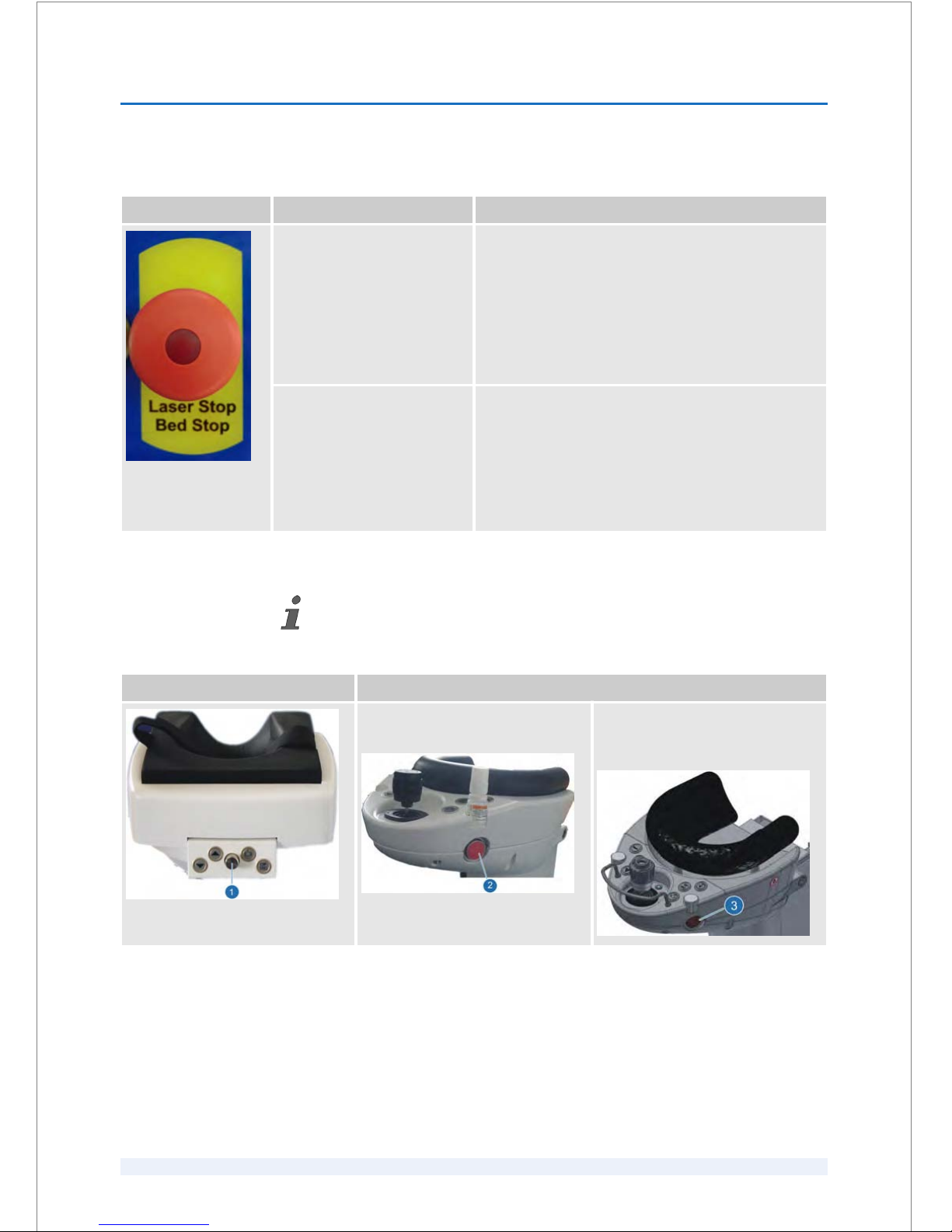
‘Laser Stop’ button with integrated ‘Bed Stop’
Action Results
To activate the ‘Laser Stop’
button:
n Press the
‘Laser Stop’
button .
Any possible laser emission stops immediately by cut‐
ting off the laser interlock.
The patient bed cannot be moved upwards or down‐
wards.
The integrated illumination in the ‘Laser Stop’ button is
no longer illuminated.
The ‘Reset’ button is illuminated simultaneousely.
To unlock the
‘Laser Stop’
button:
n Pull the
‘Laser Stop’
button towards you so
that a restart is possible.
n Press the ‘Reset’ button
(Fig. 9/5).
After 2 seconds the ‘Reset’ button is no longer illumi‐
nated (normal operation).
The integrated illumination in the ‘Laser Stop’
button is
illuminated red (normal operation).
Depending on the headrest connected to the patient bed, please note the following
warning!
Headrest with external joysticks Headrests with integrated joysticks
Red pushbutton at the headrest (at
the patient bed
‘LS Comfort’
Pushbutton at the headrest (at the
patient bed
‘Patient Support System
S60’ )
Patient beds with headrests
SAFETY
2
SKU: 70005780TPV * Version 6 * UM-100010770 GB
2 - 10
Page 27

Danger of injury due to system abort!
In emergency cases the user is able to abort the laser system by pressing the
‘Laser Stop’
button (
Ä
on page 2 - 10).
– If the system abort occurs during a treatment,
– press the silver-coded function button (
Ä
on page 2 - 10/
Headrest with external joysticks/1) at the front of the headrest when
using a patient bed with headrest and external joysticks, or
– press the red pushbutton on the side of the headrest
(
Ä
on page 2 - 10) when using a patient bed with headrest and inte‐
grated joystick.
Now, you can manually tilt the headrest downwards to release the
patient.
Refer to the respective patient bed user manual by AKRUS GmbH & Co
KG.
– Ask the patient to leave the patient bed very carefully.
– Before unlocking the ‘Laser Stop’ button, ensure that the cause of the
laser stop has been removed.
– Do not unlock the ‘Laser Stop’ button until there is no more danger and
there is no patient lying on the patient bed!
2.10 Labeling
Danger of injury due to illegible labels!
Over time, labels and signs can become dirty or illegible due to wear and
tear or fading. If labels become illegible, dangers cannot be recognized, nec‐
essary operating instructions cannot be followed, and injuries can occur.
– Always keep the labels in good condition so that they are always legible.
– If a label is damaged or has become illegible, contact an Authorized
Service Technician.
L WARNING
L WARNING
SAFETY
2
SKU: 70005780TPV * Version 6 * UM-100010770 GB
2 - 11
Page 28
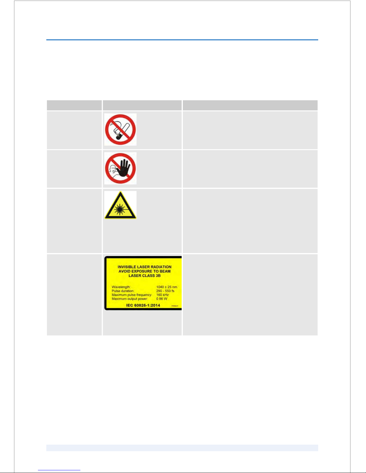
2.10.1
Labels in the operating room entrance area
The following labels must be displayed in the operating room entrance area:
Label name Label Description
No smoking Fire hazards exist from flammable or potentially explo‐
sive solid, liquid, or gaseous substances.
Unauthorized
access prohibited
Only persons authorized by the customer may enter the
operating room.
Laser beam Unauthorized persons must not enter work places
where laser beams are used and they are not permitted
to operate laser emitting equipment.
The equipment should only be operated when the user
is sure that the laser output cannot damage eyes, burn
skin or tissue, or result in damage to protective work
clothing or other objects.
Never look directly into the laser source!
Invisible laser radia‐
tion (large)
INVISIBLE LASER RADIATION
AVOID EXPOSURE TO BEAM
LASER CLASS 3B
Wavelength: 1040 ± 25 nm
Pulse duration: 290 – 550 fs
Maximum pulse frequency: 160 kHz
Maximum output power: 0.86 W
IEC 60825-1:2014
SAFETY
2
SKU: 70005780TPV * Version 6 * UM-100010770 GB
2 - 12
Page 29
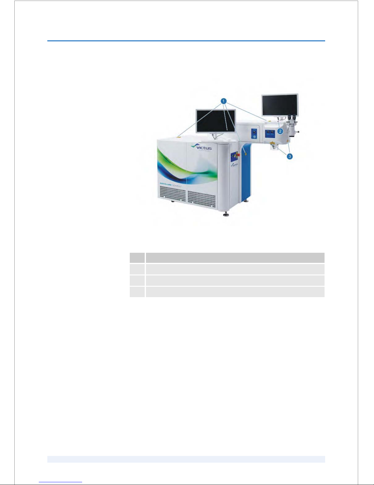
2.10.2
Labels on the laser system
Fig. 1: Front view
Pos. Label
1 Laser beam (small label); caution when cover is open
2 No heavy loads
3 Laser beam (small label); laser aperture
SAFETY
2
SKU: 70005780TPV * Version 6 * UM-100010770 GB
2 - 13
Page 30
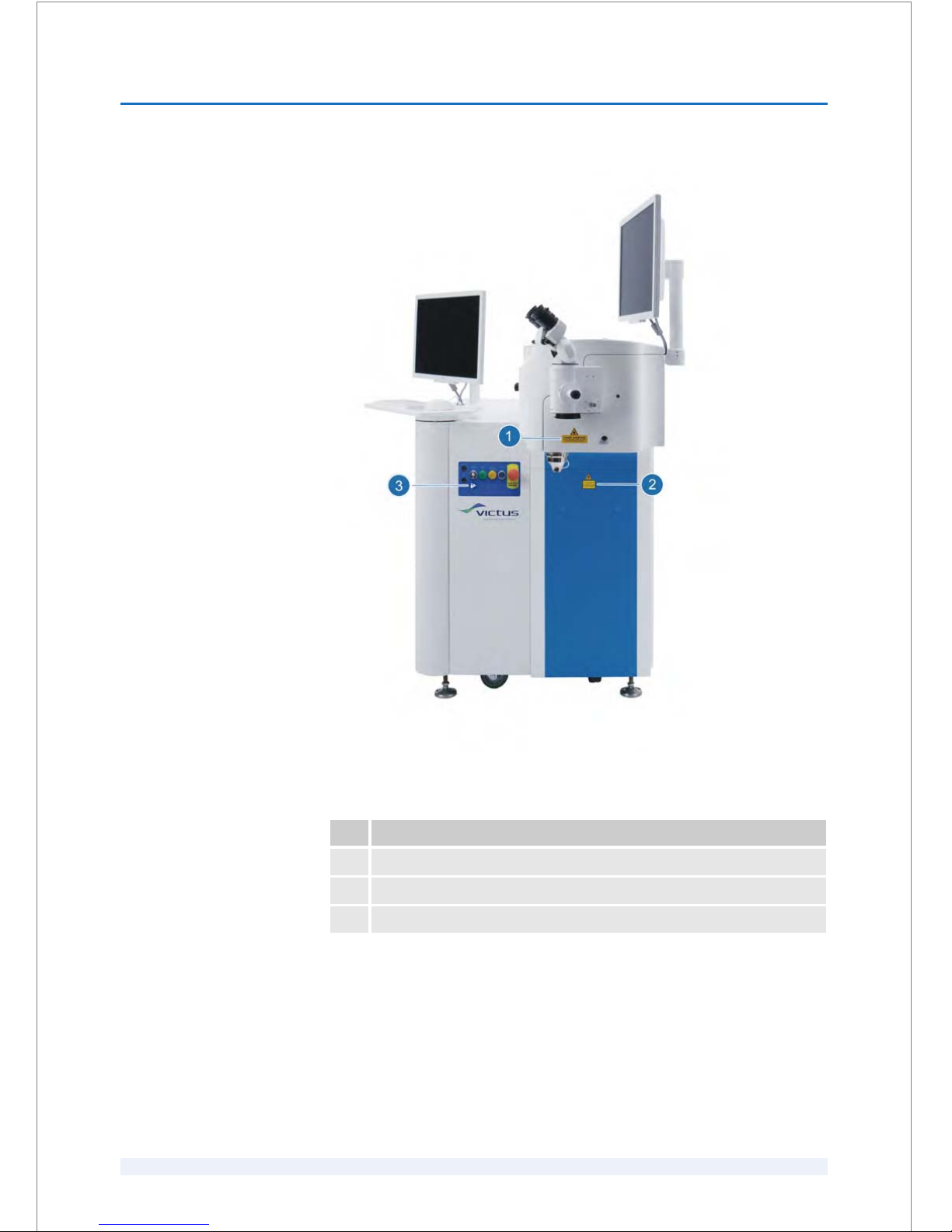
Fig. 2: Side view
Pos. Label
1 Laser beam (small label); laser aperture
2 Laser beam (small label); caution when cover is open
3 Consult operator's manual
SAFETY
2
SKU: 70005780TPV * Version 6 * UM-100010770 GB
2 - 14
Page 31
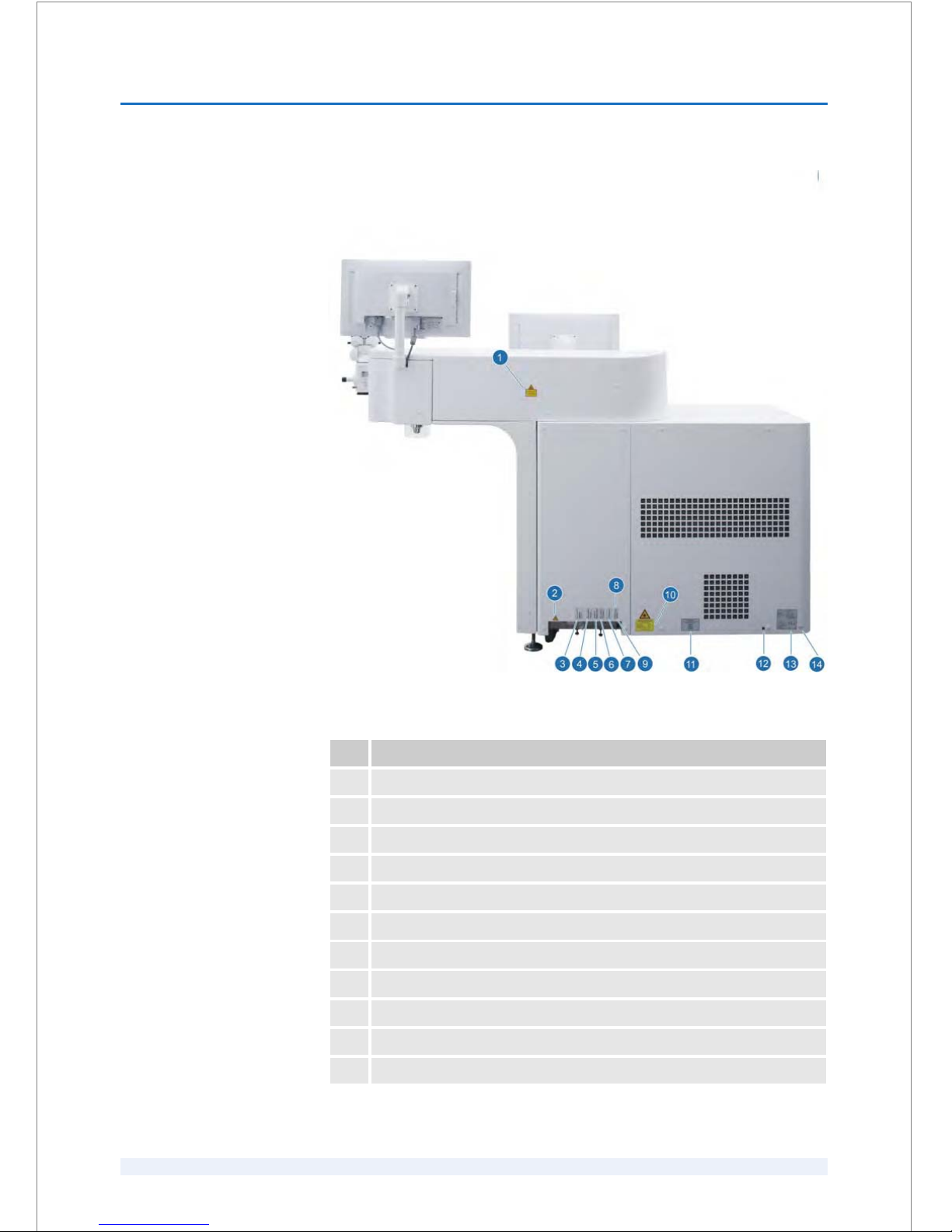
Fig. 3: Back view
Pos. Label
1 Laser beam (small label); caution when cover is open
2 High voltage (power supply of the laser system)
3 Power patient bed
4 ‘Vacuum’ footswitch
5 Interlock patient bed (interlock cable)
6 ‘Procedure’ footswitch
7 OP camera
8 Camera live image
9 Interlock external
10 Laser beam (large label); invisible laser radiation
11 Patent label
SAFETY
2
SKU: 70005780TPV * Version 6 * UM-100010770 GB
2 - 15
Page 32
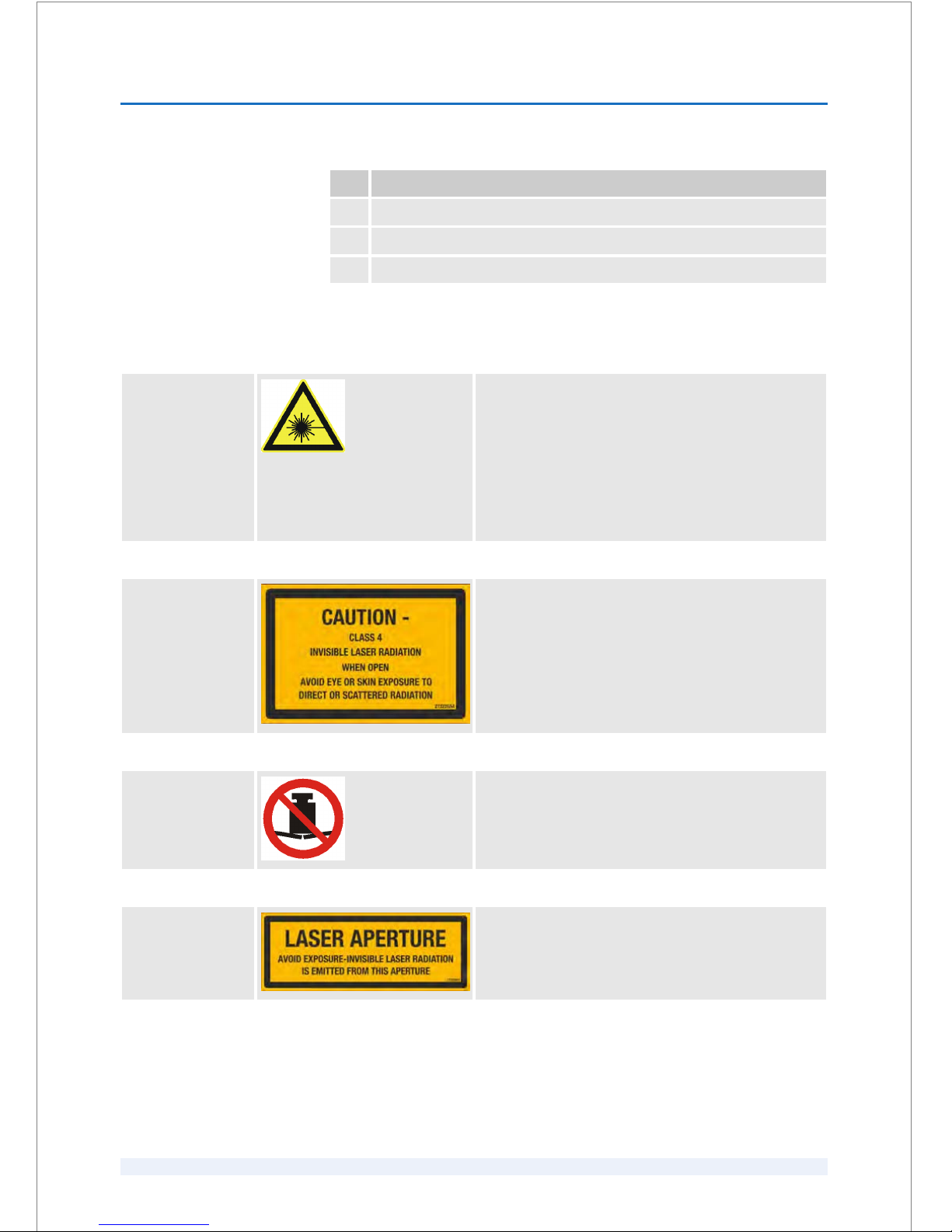
Pos. Label
12 WEEE directive
13 Type plate
14 Installed software
The following labels must be displayed on the laser system:
Laser beam Unauthorized persons must not enter work places
where laser beams are used and they are not permitted
to operate laser emitting equipment.
The equipment should only be operated when the user
is sure that the laser output cannot damage eyes, burn
skin or tissue, or result in damage to protective work
clothing or other objects.
Never look directly into the laser source!
Caution when
cover open
Caution - Class 4 Invisible laser radiation when open.
Avoid eye or skin exposure to direct or scattered radia‐
tion.
No heavy loads Do not lean or put heavy loads on the designated com‐
ponent.
Laser aperture Laser aperture - Avoid exposure - Invisible laser radia‐
tion is emitted from this aperture.
SAFETY
2
SKU: 70005780TPV * Version 6 * UM-100010770 GB
2 - 16
Page 33
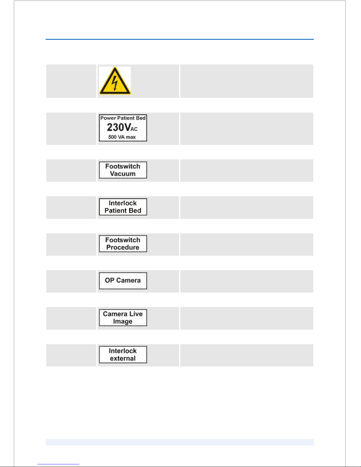
High voltage This sign warns that there are live parts with high
voltage behind the cover to which the sign is attached.
Unauthorized persons may not open covers that display
this sign.
Power Patient Bed This label shows the place of the power connection for
the patient bed.
‘Vacuum’ foot‐
switch
This label indicates the connection for the ‘Vacuum’
footswitch.
Interlock Patient
Bed
This label indicates the location of the plug for the
patient bed interlock.
‘Procedure’ foot‐
switch
This label indicates the connection for the ‘Procedure’
footswitch.
OP Camera This label indicates the location of the plug for the OP
camera.
Camera Live
Image
This label indicates the location of the plug for the
video camera.
Interlock external This label indicates the location of the plug for the inter‐
lock external.
SAFETY
2
SKU: 70005780TPV * Version 6 * UM-100010770 GB
2 - 17
Page 34
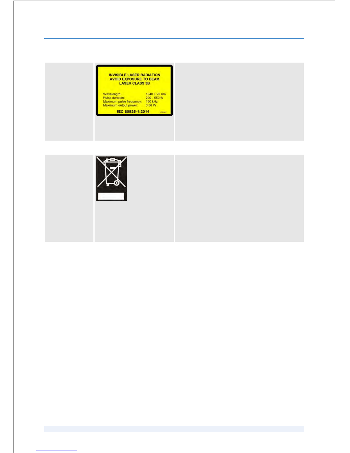
Invisible laser radi‐
ation (small)
INVISIBLE LASER RADIATION
AVOID EXPOSURE TO BEAM
LASER CLASS 3B
Wavelength: 1040 ± 25 nm
Pulse duration: 290 – 550 fs
Maximum pulse frequency: 160 kHz
Maximum output power: 0.86 W
IEC 60825-1:2014
Disposal of
electronic equip‐
ment
The European Union's WEEE Directive requires manu‐
facturers to label their electronic equipment properly
and to provide for recycling at the end of its useful life.
Technolas Perfect Vision GmbH fully complies with the
WEEE Directive. This symbol on the product indicates
that it must be separately collected and recycled in
order to protect human health and the environment.
In that regard, Technolas Perfect Vision GmbH will
arrange the collection and recycling of end-of-life Tech‐
nolas Perfect Vision GmbH equipment.
To initiate the collection of end-of-life equipment,
please contact an Authorized Service Technician.
SAFETY
2
SKU: 70005780TPV * Version 6 * UM-100010770 GB
2 - 18
Page 35
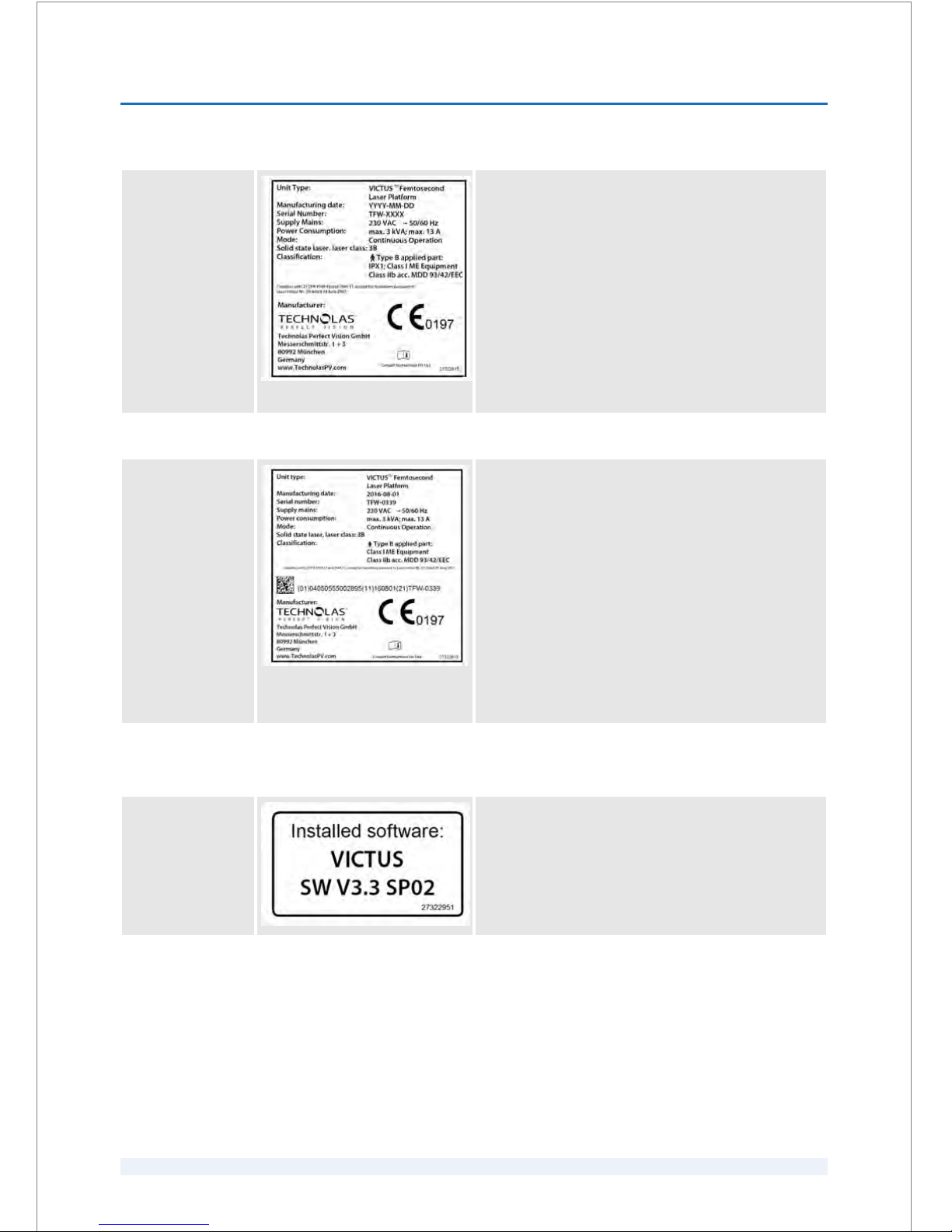
Type plate for
VICTUS™ Femto‐
second Laser Plat‐
form with serial
number £
TFW-0109 (see
back side of the
laser system)
The type plate contains the following information:
n Unit type
n Manufacturing date
Year-Month-Day
n Serial number
n Supply mains
n Power consumption
n Mode
n Classification
n Manufacturer
n CE Mark with the number of the Notified Body
Type plate for
VICTUS™ Femto‐
second Laser Plat‐
form with serial
number ³
TFW-0110 (see
back side of the
laser system)
The type plate contains the following information:
n Unit type
n Manufacturing date
Year-Month-Day
n Serial number
n Supply mains
n Power consumption
n Mode
n Classification
n Unique device identification (UDI)
n Manufacturer
n CE Mark with the number of the Notified Body
Installed software This label is located next to the type plate. On the label
you can find information about the software installed
on the laser system.
SAFETY
2
SKU: 70005780TPV * Version 6 * UM-100010770 GB
2 - 19
Page 36
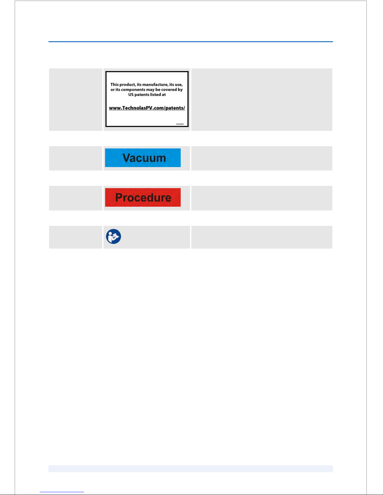
Patent Label This patent label is located next to the type plate and
refers to the website where all patents are listed under
which the VICTUS™ Femtosecond Laser Platform is man‐
ufactured or used.
‘Vacuum’ foot‐
switch
The ‘Vacuum’ footswitch is labeled with the ‘Vacuum’
label and labels from the footswitch manufacturer.
‘Procedure’ label The ‘Procedure’ footswitch is labeled with the
‘Procedure’ label and labels from the footswitch manu‐
facturer.
Follow the instruc‐
tions
Consult operator's manual.
SAFETY
2
SKU: 70005780TPV * Version 6 * UM-100010770 GB
2 - 20
Page 37

3
Transport and storage
This chapter provides information regarding the delivery, unpacking, and storage
of the laser system.
3.1
Transportation
The product will be delivered to you by a delivery company. Depending on the
form of transportation, the product may be packed in wooden boxes, or the indi‐
vidual components will be transported with other protective material.
The packaging may be removed only by an Authorized Service Technician.
Do not move or transport the product yourself.
Hazards due to unauthorized transport!
The product is very sensitive to any changes in temperature, to shocks, or
vibrations. Improper transport may result in property damage and impaired
treatments, which can cause severe injuries.
The product must only be transported by a delivery company that is author‐
ized by Technolas Perfect Vision GmbH. This requirement applies to
delivery, to in-house transports, and to external transports.
3.2 Visual inspection after delivery
The product and the required documents are given to the carrier in perfect condi‐
tion. The documents state the type and content of the delivered goods. Check the
delivery note to ensure the completeness of the delivery. The carrier is respon‐
sible for delivering the product promptly and in perfect condition. Should a loss
of parts or damage occur during transportation, the delivery company is respon‐
sible.
If there are defects or damage that have occurred during transport, perform the
following steps:
n Inform the nearest service division immediately. A delay in reporting the
damage may result in denial of the damage claim.
n Urge the delivery person to write down the kind of damage on the freight
note immediately and sign the freight note as confirmation.
n Under certain circumstances, an expert's opinion on the damage cost or the
value of lost goods can only be provided by a representative of the transport
insurance company.
n Fill in a form for the insurance company immediately. Payment for lost goods
or for repair of damaged goods can only be obtained from the transport
insurance company.
L CAUTION
TRANSPORT AND STORAGE
3
SKU: 70005780TPV * Version 6 * UM-100010770 GB
3 - 1
Page 38

If you do not detect any damage of the outside packaging, but the product is
damaged on the inside and if you think that this damage has resulted from
improper transportation, inform your distributor and the delivery company
immediately and insist on an inspection of the product. Keep the packaging
material until all questions of the delivery agent and the insurance company have
been clarified.
3.3
Storage before installation
After delivery to your clinic, hospital or practice, note the following:
n The individual parts of the shipment must be stored in a secure and dry place
before installation and initial use.
3.4 Unpacking
After delivery, the product must be unpacked and installed by an Authorized
Service Technician exclusively.
Hazards due to unauthorized unpacking!
Removal of the transport safety device in the wrong sequence may result in
damage.
– The product must only be unpacked by Authorized Service Technicians.
–
The product must not be connected before Authorized Service Techni‐
cians have made sure that it is in proper working condition before initial
operation.
Technolas Perfect Vision GmbH does not assume any liability for any damage to
the product arising from unauthorized unpacking.
L WARNING
TRANSPORT AND STORAGE
3
SKU: 70005780TPV * Version 6 * UM-100010770 GB
3 - 2
Page 39

4
Installation, commissioning, service, cali‐
bration, decomissioning and disposal
4.1
Installation and comissioning
Initial installation and commissioning are exclusively performed by Author‐
ized Service Technicians.
Unauthorized installation and commissioning will void the warranty.
Danger of serious injury in conjunction with improper service or mainte‐
nance!
The medical electrical equipment must not be serviced or maintained while
it is in use with the patient.
– Never service or maintain the medical electrical equipment while it is in
use with the patient.
Hazards due to use of unauthorized accessories / tools / devices!
Only authorized accessories, tools or devices specified in this user manual
are allowed for usage or replacement. Any damage caused by the improper
usage of unauthorized accessories, tools or devices will void the certification
and the warranty. Furthermore it may lead to increased emissions or
decreased immunity of the equipment.
– Do not use other accessories / tools / devices than the ones specified in
this user manual.
After longer periods out of operation, the conditions specified under
Ä
Chapter 11.4 ‘Transport and storage conditions’ on page 11 - 4 must be observed.
After longer periods out of operation, the laser system can be started as described
in
Ä
Chapter 6.2.3.1 ‘Switching the laser system on and off’ on page 6 - 4 and in
Ä
Chapter 8.1.1 ‘Starting and closing the software’ on page 8 - 1.
L CAUTION
L WARNING
L CAUTION
Longer periods out of opera‐
tion
INSTALLATION, COMMISSIONING, SERVICE, CALIBRATION, DECOMISSIONING AND
DISPOSAL
4
SKU: 70005780TPV * Version 6 * UM-100010770 GB
4 - 1
Page 40
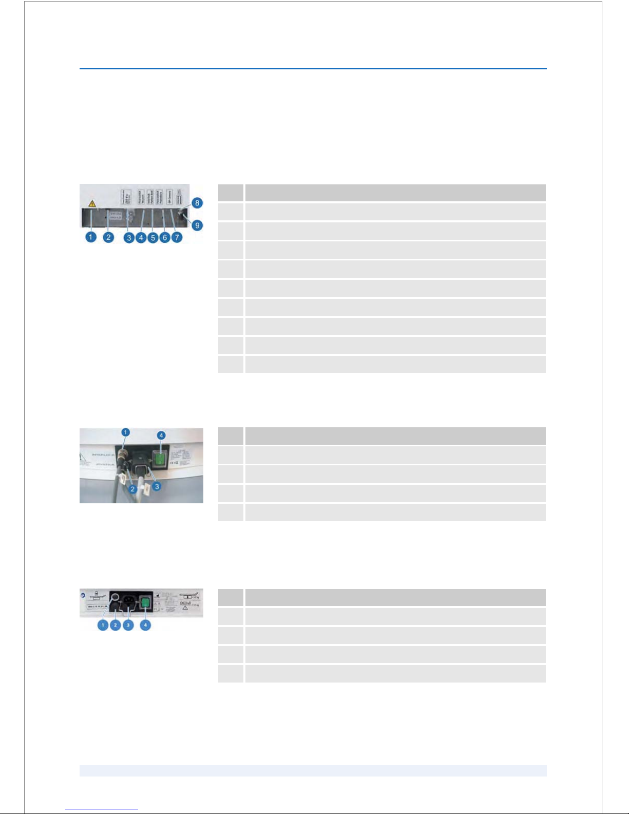
4.1.1
Interface of the patient beds "LS Comfort" and "Patient
Support System S60" by AKRUS GmbH & Co KG
Pos. Interface port
1 Power supply (laser system)
2 Main switch
3 Power patient bed
4 ‘Vacuum’ footswitch
5 Interlock cable ‘Interlock Patient Bed’
6 ‘Procedure’ footswitch
7 OP camera (optional)
8 Camera Live Image (optional)
9 Interlock external
Pos. Interface port
1 Interlock cable ‘INTERLOCK’
2 Joystick(s)
3 Power supply
4 Main switch
Pos. Interface port
1 Interlock cable
2 Not used
3 Power supply
4 Main switch
Interface ports at the
VICTUS™ Femtosecond Laser
Platform
Fig. 4: Interface ports at the VICTUS™
Femtosecond Laser Platform
Interface ports at the
patient bed "LS Comfort"
Fig. 5: Interface ports at the patient bed
"LS Comfort"
Interface ports at the
patient bed "Patient Sup‐
port System S60"
Fig. 6: Interface ports at the patient bed
"Patient Support System S60"
INSTALLATION, COMMISSIONING, SERVICE, CALIBRATION, DECOMISSIONING AND
DISPOSAL
4
SKU: 70005780TPV * Version 6 * UM-100010770 GB
4 - 2
Page 41
Danger of confusion due to identical-looking connectors at the interlock
cable!
– Check for the labels on the cable to identify the connector that corre‐
sponds to the respective interface port.
1.
Connect the laser system and the patient bed. Observe the cable labeling.
2.
Verify that all cables are connected correctly and are seated firmly. The
power cable must be snapped into place.
3.
Verify the proper function of the interlock connection. To do so, apply a ver‐
tical force of >6 N. Observe the LED indicators on the force display. The
patient bed must only be movable in the downward direction.
4.2
Service and calibration
Hazard due to improperly completed service or calibration!
Service or calibration that is completed by personnel other than Authorized
Service Technicians may result in severe injuries to persons who perform the
service, third parties or patients, and may damage the laser system.
– Service and calibration must only be performed by Authorized Service
Technicians.
If system checks fail or other errors occur, service must be performed as soon as pos‐
sible.
The service and calibration interval is 6 months.
The expected service life is 5 years.
4.3
Decomissioning and disposal
Danger of injury in conjunction with improper decommissioning and dis‐
posal!
Stored residual energies and components featuring edges, tips, and corners
on and inside the laser system or on the required tools may cause injuries.
– Decommissioning and disposal must be performed by Authorized
Service Technicians exclusively.
Technolas Perfect Vision GmbH will arrange for the collection and recycling of (a)
end-of-life Technolas Perfect Vision GmbH equipment and (b) end-of-life equip‐
ment from other manufacturers when a Technolas Perfect Vision GmbH product
is purchased to replace the older equipment and has identical functionality. To
initiate the collection of end-of-life equipment, contact an Authorized Service
Technician.
NOTICE
L WARNING
When do perform service
and calibration
Service life
L WARNING
INSTALLATION, COMMISSIONING, SERVICE, CALIBRATION, DECOMISSIONING AND
DISPOSAL
4
SKU: 70005780TPV * Version 6 * UM-100010770 GB
4 - 3
Page 42

INSTALLATION, COMMISSIONING, SERVICE, CALIBRATION, DECOMISSIONING AND
DISPOSAL
4
SKU: 70005780TPV * Version 6 * UM-100010770 GB
4 - 4
Page 43

5
Clinical applications
The use of the laser system is the particular responsibility and is at the discretion
of the user once the therapeutic benefits and possible complications and side
effects have been considered.
Do not exceed a total exposure duration of one hour of the eye to the LED
ring, as ophthalmic damage could occur.
5.1
Medical indications
This section provides information about the available procedures for specific indi‐
cations.
Medical indication Procedure
Cataract Capsulotomy
Cataract Lens fragmentation
Cataract Corneal incisions
In addition, arcuate incisions are available as part of a cataract treatment.
Medical indication Procedure
LASIK flap Flap
Medical indication Procedure
Miscellaneous diseases of
the cornea
Penetrating keratoplasty (PKP)
Keratoconus Intracorneal ring segments tunnel (ICRS tunnel),
crosslinking (CXL)
Opacity of the cornea or
superficial injury
Lamellar keratoplasty (LKP)
Keratectasia Intracorneal ring segments tunnel (ICRS tunnel),
crosslinking (CXL)
L CAUTION
Cataract procedures
Corneal procedures
Therapeutic procedures
CLINICAL APPLICATIONS
5
SKU: 70005780TPV * Version 6 * UM-100010770 GB
5 - 1
Page 44

5.2 Patient selection criteria
Danger of injury due to the failure to observe the patient selection criteria!
Failure to observe the contraindications may result in serious permanent
patient injury.
– Observe the contraindications in
Ä
Chapter 5.2.1 ‘Contraindications’
on page 5 - 2.
5.2.1
Contraindications
Limitations for usage of the laser system correspond to the exclusion criteria
known to be associated with such applications.
Patients with pacemakers
The cover of the laser is designed in a way that electromagnetic fields are minimized.
Nevertheless, special precaution must be taken when treating patients with pace‐
makers. Patients with pacemakers should only be treated in the presence of an
anesthetist and after consultation with their cardiologist.
n Corneal opacity that would interfere with the laser beam.
n Pediatric surgery, patients under the age of 18 years or legal age.
n All valid exclusion criteria for the intended treatment like:
–
glaucoma and suspected glaucoma
– diabetes mellitus
– retinal disorders
– rheumatic diseases
– occlusion of retinal vessels
– pellucid marginal degeneration
– herpes zoster or herpes simplex keratitis
– heavy vascularization of the ocular tissue
– epilepsy
– recurrent corneal erosion
– severe basement membrane disease
– patients who suffer from severe wound-healing disorders such as con‐
nective tissue disease, autoimmune illnesses, immunodeficiency illnesses,
endocrine diseases, lupus, rheumatoid arthritis, collagenosis, or clinically
significant atopy
– patients suffering from AIDS or HIV.
n Valid exclusion criteria that complicate the docking procedure like:
– chemosis
– significant loss of stability of the conjunctiva
– nystagmus
– On a keratometric map of the cornea, the minimum and maximum K-
values of the central 3 mm zone must not differ by more than 5 D.
– The maximum K-values must not exceed 60 D. The minimum value must
not be smaller than 37 D.
n Patients who are pregnant or nursing.
L WARNING
The following criteria apply
to all procedures:
CLINICAL APPLICATIONS
5
SKU: 70005780TPV * Version 6 * UM-100010770 GB
5 - 2
Page 45

n Patients who are blind in the fellow eye.
n Known sensitivity to planned concomitant medications.
n Patients with a recurrent or active ocular or uncontrolled eyelid disease.
n Previous corneal surgery of any kind
n Dry eye diseases
n Cataract
n Patients with signs of progressive or unstable myopia in the eye that requires
treatment.
n Keratoconus and suspected keratoconus.
n Subjects with a poorly dilating pupil.
n Patients with an anterior chamber depth (ACD) < 1.5 mm or ACD > 4.8 mm as
measured by ultrasonic examination.
n Presence of blood or other material in the anterior chamber.
n A history of lens instability (e.g. posterior polar cataract, traumatic cataract) or
zonular instability.
n Dry eye diseases
n Previous corneal surgery specifically incisions that might provide a potential
space into which the gas produced by the procedure can escape.
n Corneal thickness requirements that are beyond the range of the system.
n Keratoconus and suspected keratoconus (only applicable for
arcuate incisions).
n Previous corneal surgery of any kind.
5.3 Available procedures
Danger of injury due to the failure to observe the patient selection criteria!
Failure to observe the contraindications may result in serious permanent
patient injury.
– Observe the contraindications listed in the relevant chapter of this user
manual.
5.3.1
Cataract procedures
The cataract treatment comprises the following procedures:
n Capsulotomy
n Lens fragmentation
n Arcuate incisions
n Corneal incisions
In addition, the following
applies to flap used in
LASIK:
In addition, the following
applies to capsulotomy and
lens fragmentation:
In addition, the following
applies to arcuate incisions
and corneal incisions:
In addition, the following
applies to the therapeutic
procedures:
L WARNING
CLINICAL APPLICATIONS
5
SKU: 70005780TPV * Version 6 * UM-100010770 GB
5 - 3
Page 46

With this procedure, the anterior capsulotomy is performed intraocularly by
means of the laser system. The correct positioning of the capsulotomy cut on the
anterior capsular surface can be verified by means of an integrated optical coher‐
ence tomography (OCT) device before starting the cutting process.
This procedure generates precise cuts inside the cataractous lens, leading to a
softening and fragmentation of the lens. The correct positioning of the cuts inside
the lens can be verified by means of an OCT before starting the laser-assisted
fragmentation process.
With this procedure, the laser system is used for patients undergoing cataract sur‐
gery or other ophthalmic treatment requiring penetrating cuts / incisions in the
cornea.
This procedure creates cuts in the outer area of the cornea and very close to the
sclera. These penetrating cuts / incisions are done at patients undergoing a cata‐
ract surgery for direct access into the eye. The correct position and shape of the
cuts can be verified by the video image.
5.3.2
Corneal procedures
The corneal treatment comprises the following procedure:
n Flap
This procedure cuts a corneal flap. The flap is generated by cutting a bed parallel
to the anterior surface of the cornea and a rim or side cut with a hinge. This proce‐
dure enables the user to define flap parameters such as the depth, the diameter
of the bed, the position and the width of the hinge, and the angle of the rim cut in
relation to the cornea.
5.3.3
Therapeutic procedures
The therapeutic treatment comprises the following procedures:
n Crosslinking
n Intracorneal ring segments tunnel
n Lamellar keratoplasty
n Penetrating keratoplasty
The crosslinking software module provides certain advantages compared to the
conventional method. By creating a bed and incisions for inserting Riboflavin, the
Riboflavin does not have to be dripped onto the eye but can be inserted directly
under the bed, and the cornea absorbs the Riboflavin faster. Furthermore, the epi‐
thelium does not have to be removed.
Capsulotomy
Lens fragmentation
Arcuate incisions
Corneal incisions
Flap
Crosslinking
CLINICAL APPLICATIONS
5
SKU: 70005780TPV * Version 6 * UM-100010770 GB
5 - 4
Page 47

This procedure allows the user to set parameters such as depth, position, and
number of the entrance incision(s).
This procedure allows to create intrastromal channel incisions for nearly all types
and sizes of ring segments. The results achieved are especially convincing in the
treatment of keratoconus and ectasia. The incision follows the natural curvature
of the cornea and enables optimal positioning of ICRS inside the stroma. The
diameter, width, depth of the tunnel incisions and entrance incisions are individu‐
ally adjustable.
Lamellar keratoplasty is usually performed when a superficial injury, opacity, or
scarring of the cornea reduces visual acuity. The damaged cornea is removed and
replaced by a healthy donor cornea. Lamellar keratoplasty has the advantage of
being primarily extraocular and therefore preserves the recipient endothelium.
This procedure allows the user to cut the donor and recipient cornea with
matching diameters and rim angles. This method facilitates better wound closure.
This procedure allows to cut a penetrating keratoplasty into the donor cornea as
well as into the recipients cornea. Diameter and depth are individually adjustable.
Intracorneal ring segments
tunnel
Lamellar keratoplasty
Penetrating keratoplasty
CLINICAL APPLICATIONS
5
SKU: 70005780TPV * Version 6 * UM-100010770 GB
5 - 5
Page 48

CLINICAL APPLICATIONS
5
SKU: 70005780TPV * Version 6 * UM-100010770 GB
5 - 6
Page 49
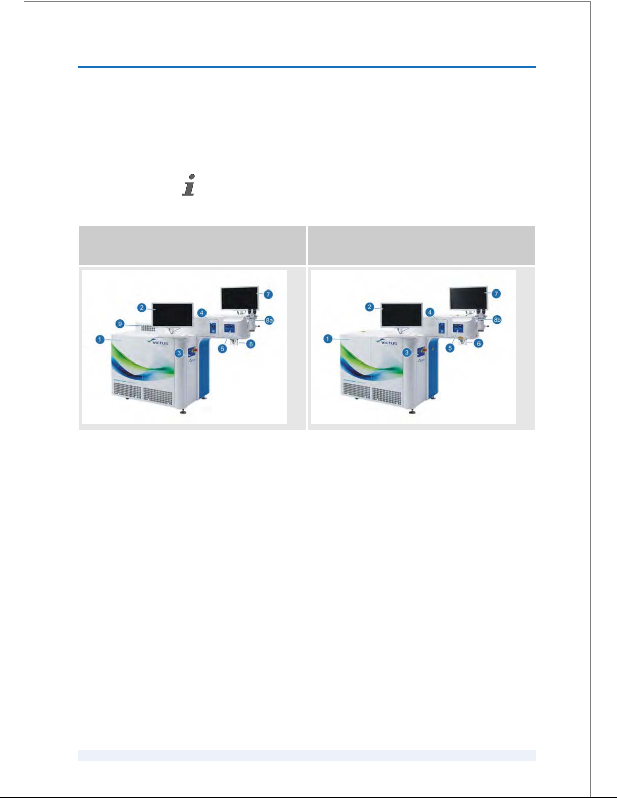
6
Hardware
6.1
Overview on the components
Depending of the laser system, the position of the surgical microscope illumination
in the VICTUS™ Femtosecond Laser Platform can differ as described below.
VICTUS™ Femtosecond Laser Platform with surgical
microscope illumination on the top of the laser
system
VICTUS™ Femtosecond Laser Platform with surgical
microscope illumination integrated in the laser
system
1 Main unit
2 Assistant workstation
3 Start-up panel
4 Suction status controller and force display
5 Panel with knob for switching on/off laser ring light and another knob for
shifting the camera focus between corneal and lens treatments
6 Spacer cone with protection cover
7 Surgeon control screen
8a Surgical microscope (optional)
8b Surgical microscope with illumination unit integrated in the laser system and
footswitch for adjusting the illumination (optional)
9 Surgical microscope illumination
HARDWARE
6
SKU: 70005780TPV * Version 6 * UM-100010770 GB
6 - 1
Page 50

6.2 Operating the hardware
6.2.1
Main unit
The main unit consists of the following components:
Component Description
Assistant
workstation
Allows to perform the system tests, to enter and manage the patient data, to select and pro‐
gram procedures, to apply vacuum for PI 125 and suction clip, to adjust the procedure
according to the patient's eye and to export treatment records.
Chiller Helps to ensure that the main components are kept at a steady temperature.
Controller Checks the connectivity among all electronic components.
GUI PC Interface between the user and the laser system.
Laser source Generates the laser beam.
Optical unit Controls the complete laser beam path.
Surgeon control
screen
Shows a life camera image, a life OCT image, and all relevant parameters for the selected treat‐
ment.
Treatment
illumination
Contains the laser ring light module. It illuminates the treatment area.
OCT Monitors cataract, corneal and therapeutic treatments.
The core of the main unit is the laser source that generates the laser beam. All other components control and
sustain the treatment process.
The following components are optional:
Optional
component
Description
Surgical microscope Allows for centering the suction clip.
Surgical microscope
illumination
Provides a uniform and adjustable illumination.
HARDWARE
6
SKU: 70005780TPV * Version 6 * UM-100010770 GB
6 - 2
Page 51
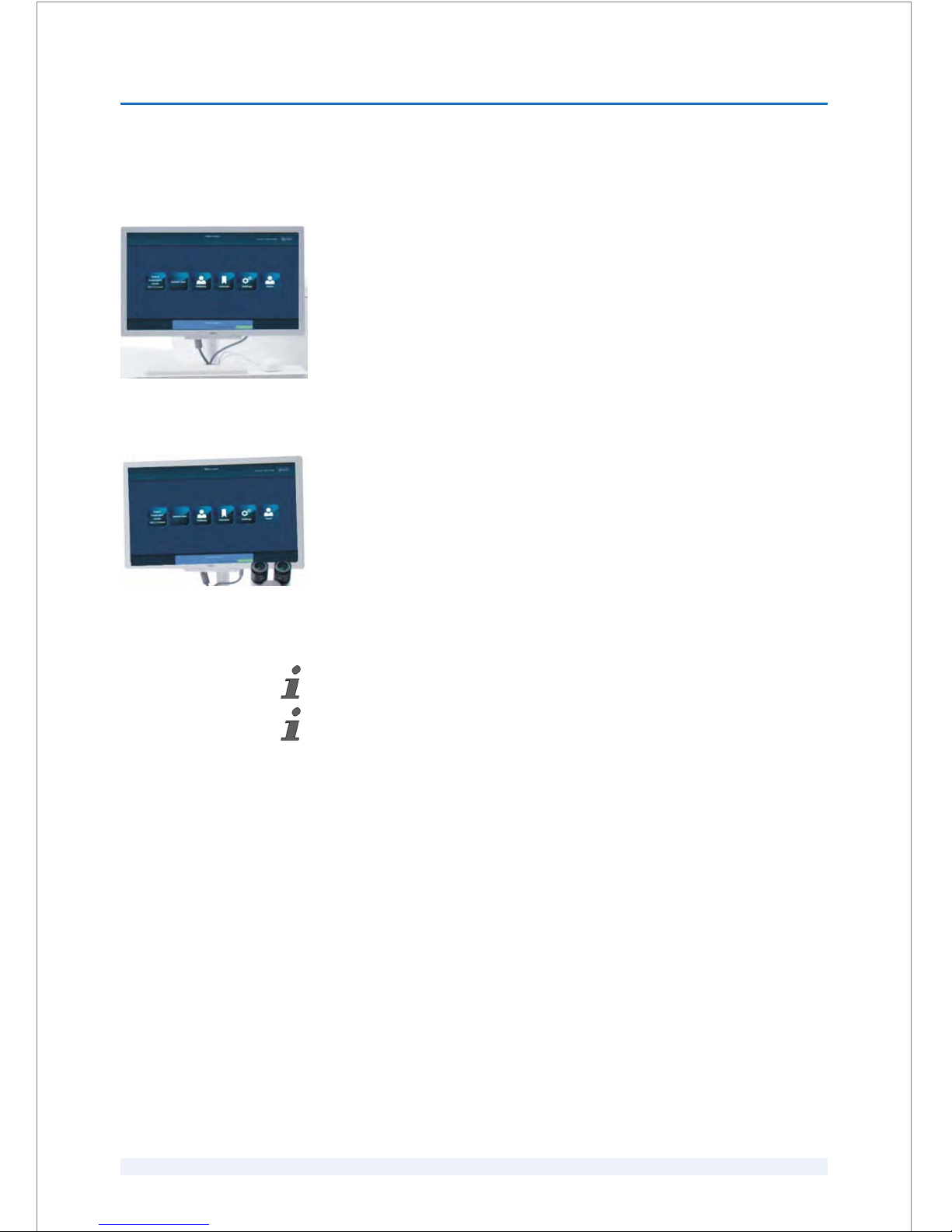
6.2.2
Assistant workstation / surgeon control screen
The assistant workstation (Fig. 7) consists of a monitor, a standard keyboard and a
standard mouse. The monitor is mounted on a rotating arm and can be tilted.
The mouse is also used for the surgeon control screen (
Ä
‘Surgeon control screen’
on page 6 - 3).
The surgeon control screen (Fig. 8) consists of a monitor and the standard mouse
from the assistant workstation (Fig. 7). The monitor is mounted on a rotating arm
and can be tilted.
The surgeon control screen displays a live camera image and a live OCT image for
cataract, corneal and therapeutic treatments. The screen also shows all relevant
information about the main treatment parameters, vacuum and pressure status,
as well as treatment progress.
6.2.2.1
Adjusting the monitor settings
For best visual accuracy it is recommended not to run the monitor in [ECO] mode.
Refer to the user manual of the monitor that you use.
Assistant workstation
Fig. 7: Assistant workstation (example)
Surgeon control screen
Fig. 8: Surgeon control screen (example)
HARDWARE
6
SKU: 70005780TPV * Version 6 * UM-100010770 GB
6 - 3
Page 52
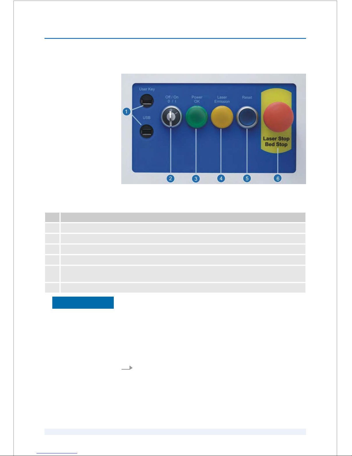
6.2.3
Start-up panel
Fig. 9: Start-up panel
Pos. Function
1 USB ports
2 System key-operated ‘Off’/ ‘On’ switch
3 Indicator for the power supply
4 ‘Laser Emission’ indicator during a running procedure.
5 ‘Reset’ button to unlock the laser system if the
‘Laser Stop’ button has been pressed, or after a system
error and also by starting the laser system.
6 ‘Laser Stop’ button with integrated ‘Bed Stop’ function.
Property damage due to use of unauthorized accessories / tools / devices!
Only USB memory sticks specified in this user manual must be inserted into
the USB ports.
– Do not insert other tools than the one specified in this user manual into
the USB ports. Failure to observe these instructions may damage the
laser system.
6.2.3.1
Switching the laser system on and off
1.
Turn the system key (Fig. 9/2) to the ‘On’ position. The ‘Power OK’ button
(Fig. 9/3) lights up.
ð
A system self test runs for 5-10 minutes.
NOTICE
Switching on
HARDWARE
6
SKU: 70005780TPV * Version 6 * UM-100010770 GB
6 - 4
Page 53
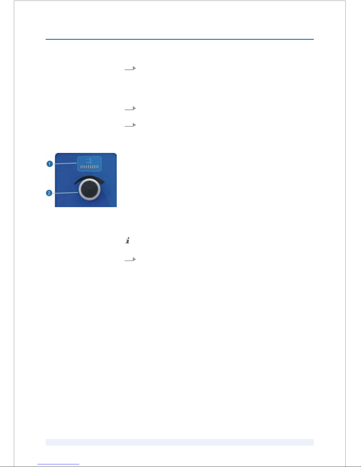
2.
For initial start-up, wait at least 20 minutes to allow the cooling unit (chiller)
to provide the required temperature. Press the blue
‘Reset’ button
(Fig. 9/5) to start the laser source and wait for at least 20 minutes (auto‐
matic countdown).
1.
Turn the system key (Fig. 9/2) to the
‘Off’ position. The laser system shuts
down with a safety delay of 5 minutes.
2.
Remove the system key.
6.2.4
Suction status controller
The suction status controller (Fig. 10) allows the user to set the suction pressure
for the suction clip. The vacuum decrease/increase is indicated by means of the
LED bar display (Fig. 10/1). The range is from 350 mbar (1 LED illuminated) to 550
mbar (10 LEDs illuminated).
6.2.4.1
Adjusting the suction status
It is not possible to exceed the preset standard suction range in either direction.
Turn the controller (Fig. 10/2) clockwise to increase or counterclockwise to
decrease the suction. The LED bar display (Fig. 10/1) indicates the suction
pressure.
Switching off
Fig. 10: Suction status controller
HARDWARE
6
SKU: 70005780TPV * Version 6 * UM-100010770 GB
6 - 5
Page 54
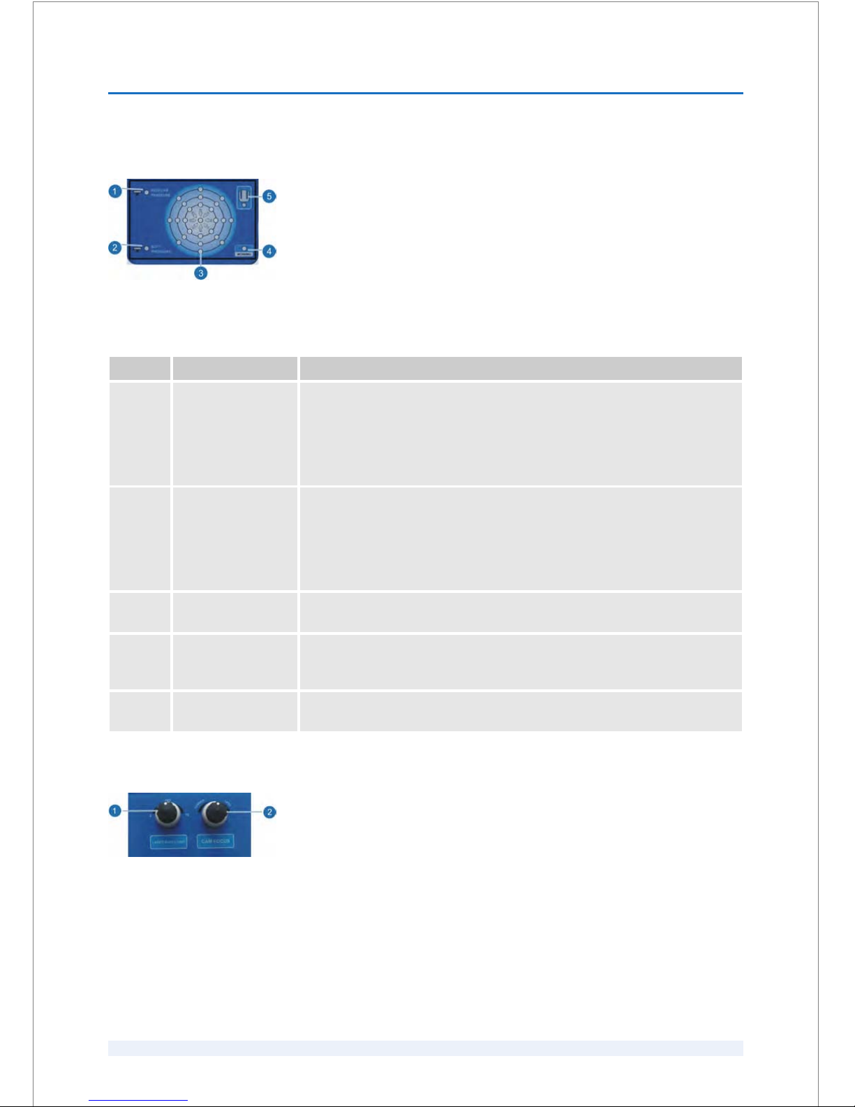
6.2.5
Force display
The force display (Fig. 11) is a control device that indicates important treatment
parameters.
Pos. Name Description
1 ‘REGULAR
PRESSURE’
LED
While docking the patient's eye to the laser system with regular pressure, the
‘REGULAR PRESSURE’
LED (Fig. 11/1) gives the surgeon additional information
about the pressure. If Fig. 11/1 is referred to, this LED will be stably illuminated
when the docking pressure is correct. This is only valid for corneal treatments,
therapeutic treatments, the arcuate incisions procedure and the corneal
incisions procedure!
2 ‘SOFT PRESSURE’
LED
While docking the patient's eye to the laser system for cataract treatments, the
‘SOFT PRESSURE’
LED (Fig. 11/2) gives the surgeon additional information
about the pressure. If Fig. 11/2 is referred to, this LED will be stably illuminated
when the docking pressure is correct. This is only valid for cataract treat‐
ments, except for the arcuate incisions procedure and the corneal incisions
procedure!
3 Shear force LEDs 25 LEDs display the shear forces that are exerted on the eye (Fig. 11/3). The
LEDs are arranged in a circle.
4 ‘WORKING’ control
LED
After starting up the laser system, the force display performs a self check. Each
of the shear force (x/y-) and vertical force (z-) LEDs blinks twice. When the
check is completed, the control LED (Fig. 11/4) is illuminated green.
5 Position of the
patient
6.2.6
Laser ring light illumination switch
The laser ring light illumination switch (Fig. 12/1) allows the user to switch the
illumination of the laser ring light on/off.
Fig. 11: Force display
Fig. 12: Laser ring light illumination
HARDWARE
6
SKU: 70005780TPV * Version 6 * UM-100010770 GB
6 - 6
Page 55

6.2.6.1
Switching the laser ring light illumination on and off
1.
Switch on the laser ring light illumination by turning the knob as follows
(Fig. 12/1):
n Position
‘2’: 2 LEDs are illuminated (for less reflection while centering
the pupil)
n Intermediate positions between ‘2’ and ‘OFF’
n Intermediate positions between ‘OFF’ and ‘10’
n Position ‘10’: 10 LEDs are illuminated (for centering the pupil while
docking)
2.
Switch off the laser ring light illumination by turning the knob to the
‘OFF’
position.
6.2.7
Camera focus switch
The camera focus switch (Fig. 12/2) allows to shift the camera focus for corneal
and lens treatments.
6.2.7.1
Adjusting the camera focus
By turning the switch ‘CAM FOCUS’ (Fig. 12/2) clockwise the OP camera
focuses on the lens, and by turning the switch counterclockwise the OP
camera focuses on the cornea.
6.2.8
Spacer cone
Property damage due to an unprotected spacer cone!
The spacer cone is very delicate and may be damaged when it is not pro‐
tected.
– Always protect the spacer cone with its protection cover when the laser
system is not in use.
The spacer cone is the exit aperture of the laser beam. During treatment, the PI
125 and the patient are docked to the spacer cone via a vacuum.
NOTICE
HARDWARE
6
SKU: 70005780TPV * Version 6 * UM-100010770 GB
6 - 7
Page 56
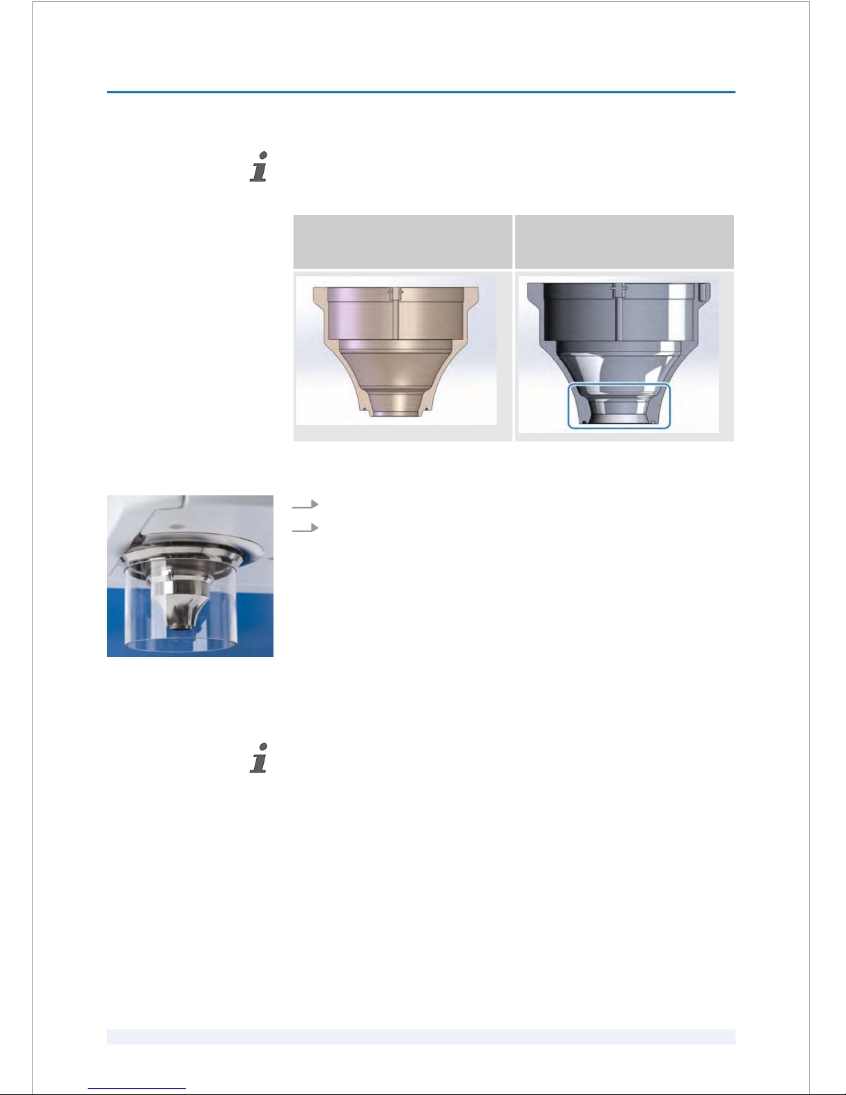
Depending on the configuration of your laser system, the appropriate spacer cone
(
Ä
on page 6 - 7) is installed which works only with the corresponding PI 125.
"Spacer cone 9,5 + 10,5" (REF 14078)
to be used for the PI 125
(REF 90000115):
"Spacer cone V4" (REF 14540) to be
used for the PI 125 (REF 90000145):
6.2.8.1
Protecting the spacer cone
1.
Slide the protection cover (Fig. 13) into the slot.
2.
Turn the protection cover clockwise until it engages.
6.2.9
Surgical microscope and its illumination
The surgical microscope and the surgical microscope illumination are optional com‐
ponents.
The surgical microscope allows the surgeon to center the suction clip on the
patient's eye.
Fig. 13: Spacer cone with protection
cover (example)
HARDWARE
6
SKU: 70005780TPV * Version 6 * UM-100010770 GB
6 - 8
Page 57
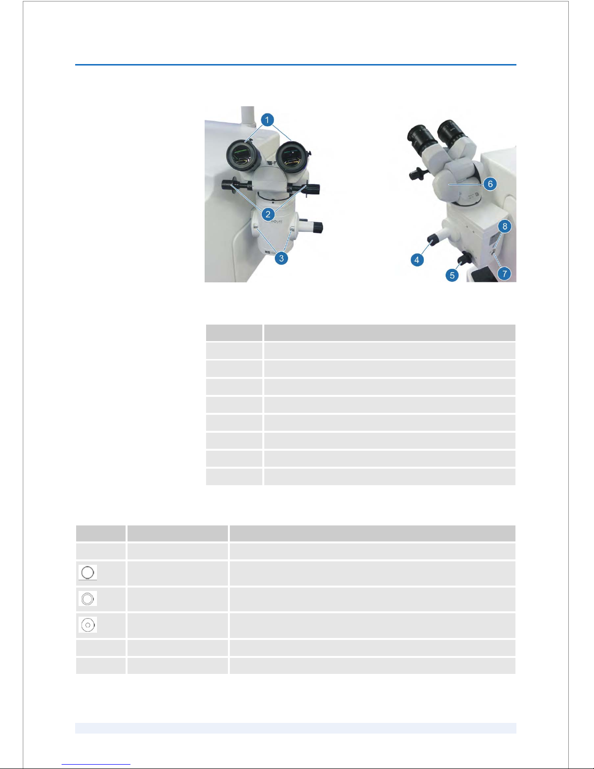
Fig. 14: Surgical microscope components
Pos. Function
1 Ocular lenses, adjustable
2 Ocular distance adjustment
3 Magnification displays
4 Magnification adjustment (5 different magnification settings)
5 Filter selection
6 Tilting joint
7 Fiber optics entry
8 Unlocking fiber optics
Pos. Filter Filter description
‘UV’ UV filter Yellowness of the light; recommended for ophthalmology
Wide aperture: 5 mm Optimum color fidelity
Spot: 2.65 mm Optimum color fidelity
Mini spot: 0.25 mm Optimum color fidelity
‘DF’ Daylight filter Adaptation of halogen light to daylight
‘Blue’ Blue filter Stimulation of fluorescence; temporary application with flourescein
Surgical microscope
components
Surgical microscope filters
HARDWARE
6
SKU: 70005780TPV * Version 6 * UM-100010770 GB
6 - 9
Page 58
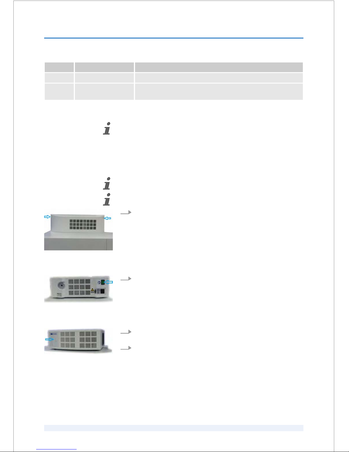
Pos. Filter Filter description
‘Green’ Green filter Contrast enhancement during operations on blood vessels
‘SF’ Soft filter Adaptation of LED light to halogen light; recommended for ophthal‐
mology
6.2.9.1
Adjusting the surgical microscope illumination
Depending on the position of the surgical microscope illumination, adjust the illu‐
mination as described below.
The illumination unit is positioned under a cover on the top of the laser system
(Fig. 15).
The illumination of the surgical microscope is permanently switched on!
1.
Remove the cover of the surgical microscope illumination (Fig. 15).
2.
Switch on the
‘I/0’ power switch at the rear panel of the surgical micro‐
scope illumination (Fig. 16).
3.
Adjust the illumination with the finger touch slider at the front panel
(Fig. 17).
4.
Close the cover of the surgical microscope illumination.
For surgical microscope illu‐
minations that are posi‐
tioned on the top of the
laser system:
Fig. 15: Cover of the surgical microscope
illumination
Fig. 16: Power switch at the surgical
microscope illumination
Fig. 17: Slider at the surgical microscope
illumination
HARDWARE
6
SKU: 70005780TPV * Version 6 * UM-100010770 GB
6 - 10
Page 59
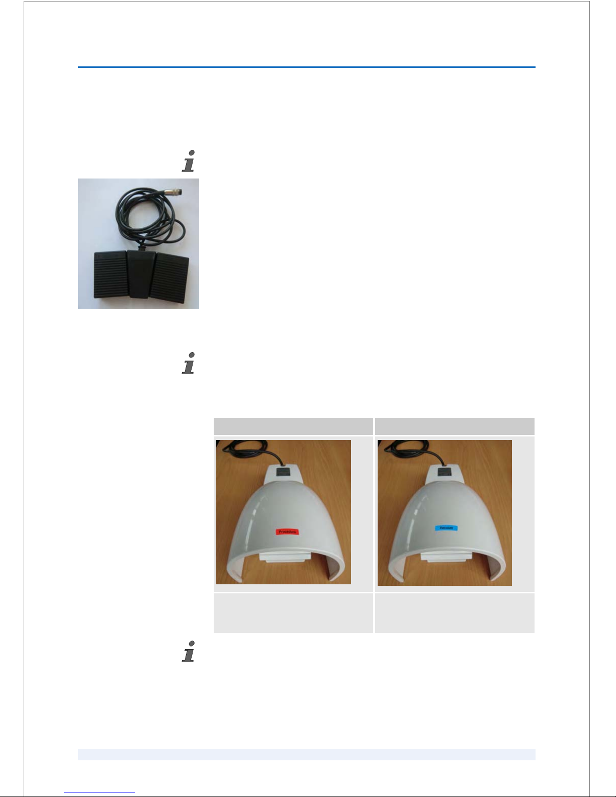
The illumination unit is positioned inside the laser system. It will be automatically
switched on when the laser system is started.
The footswitch (Fig. 18) adjusts the brightness of the surgical microscope. The left
pedal of the footswitch is used to darken the picture or to switch off the surgical
microscope; the right pedal is used to increase the brightness. The brightness
increment is more finely graduated and no longer linear.
The cable at the footswitch is connected to the surgical illumination unit.
If the laser system is running over night, remember to switch off the surgical micro‐
scope illumination by pressing the left footswitch (Fig. 18)!
6.2.10
Footswitches
‘Procedure’ footswitch ‘Vacuum’ footswitch
The ‘Procedure’ footswitch has a red
label and starts and controls the proce‐
dures.
The ‘Vacuum’ footswitch has a blue
label and activates/deactivates the
vacuum of the suction clip.
It is impossible to deactivate the vacuum of the suction clip with the ‘Vacuum’ foot‐
switch during the treatment in order to avoid suction loss, which would lead to proce‐
dure abort.
Aborting the treatment by pressing the ‘Stop’ button in the GUI will automatically
deactivate the vacuum.
For surgical microscope illu‐
minations that are inte‐
grated in the laser system:
Fig. 18: Footswitch for adjusting the sur‐
gical microscope illumination
HARDWARE
6
SKU: 70005780TPV * Version 6 * UM-100010770 GB
6 - 11
Page 60
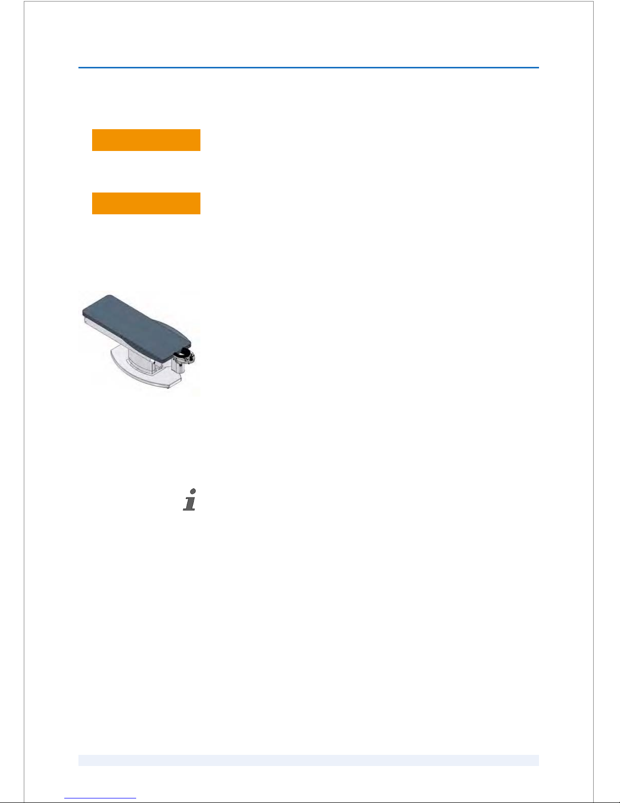
6.2.11
Patient bed
Danger of injury due to overloading the patient bed!
The patient bed is designed for a maximum patient weight of 135 kg. Over‐
loading the patient bed may result in serious and permanent patient injury.
– Do not overload the patient bed!
Risk of non-compliance of the ME system safety due to connecting the power
supply of the patient bed to another equipment than the laser system!
The power supply for the patient bed may only be supplied from the laser
system. Connecting the power supply of the patient bed to another equip‐
ment than the laser system may result in the loss of the ME system safety.
– Ensure that the power cable at the patient bed is connected to the inter‐
face port
‘Power patient bed’ at the laser system.
This figure (Fig. 19) shows an example of a patient bed that can be combined with
the VICTUS™ Femtosecond Laser Platform.
6.2.11.1
Referencing the patient bed
If the patient bed "LS Comfort" or "Patient Support System S60" by AKRUS is used,
this patient bed must be referenced at every time the laser system is switched on
or after a power failure.
Refer to the user manual "Laser Patient Bed LS Comfort" or "Patient Support System
PSS S60" by AKRUS GmbH & Co KG.
L WARNING
L WARNING
Fig. 19: Patient bed
HARDWARE
6
SKU: 70005780TPV * Version 6 * UM-100010770 GB
6 - 12
Page 61
6.3 Cleaning instructions
Danger of property damage due to the use of improper cleaning agents!
The product may be damaged if it is cleaned with improper cleaning agents
or scratching cleaning materials, such as cloths.
– Do not use solvents or lubricants.
–
Do not use ether, acetone, concentrated acids, or bases.
– Do not use abrasive cleaning agents or cleaning agents with ammonia or
other possibly caustic products.
– Do not use any steel wool or metal brushes.
– Before using a cleaning agent, test it on an inconspicuous area to check
if the cleaning agent damages the material.
Use disinfectants recommended by local institutes for hygiene or microbiology.
You can use any standard neutral to slightly alkaline cleaning agent.
Use only soft lint-free cleaning cloths.
Part of the laser system Cleaning agent
All matte surfaces Neutral or slightly alkaline cleaning agent
All lacquered surfaces Neutral or slightly alkaline cleaning agent
Spacer cone Alcohol
Oculars of the microscope Alcohol
LCD screens Commercially available cleaning kits for computers
Keyboard and mouse of the assistant work‐
station
Neutral or slightly alkaline cleaning agent
1.
Switch off the laser system.
2.
Ensure that no moisture enters the laser system.
3.
Dilute the cleaning agent with water.
4.
Soak a cleaning cloth in the diluted solution.
5.
Wring out the cleaning cloth very well.
6.
Wipe the laser system with the damp cleaning cloth.
7.
Wipe the laser system with a dry cloth.
Which cleaning agents and
disinfectants to use
NOTICE
Cleaning the laser system
HARDWARE
6
SKU: 70005780TPV * Version 6 * UM-100010770 GB
6 - 13
Page 62

NOTICE! Contamination of the spacer cone lens occurs if alcohol enters the
spacer cone!
Contaminations of the spacer cone lens can only be removed by Authorized
Service Technicians.
– Do not spray alcohol into the spacer cone.
Wipe the spacer cone with a lint-free cleaning cloth and some alcohol.
Wipe the oculars with a lint-free cleaning cloth and some alcohol.
1.
Switch off the laser system.
2.
Use a soft dry cleaning cloth to wipe the keyboard.
NOTICE! Danger of property damage due to aggressive cleaning agents
and moisture!
The assistant workstation and surgeon control screen are electronic devices
and are made of plastics.
– Do not use cleaning agents or abrasive powders that dissolve plastics.
–
Ensure that no moisture enters the assistant workstation or the surgeon
control screen.
– Ensure that the ventilation slots of the monitors remain open.
3.
Follow the instructions on the cleaning kit for computers to clean the assis‐
tant workstation and the surgeon control screen.
1.
Switch off the laser system.
2.
Wipe the mattress of the patient bed with a damp soft cloth.
3.
Wait until the patient bed is dry before using it.
Refer to the user manual of the patient bed that you use.
Cleaning the spacer cone
Cleaning the oculars of the
surgical microscope
Cleaning the assistant work‐
station and the surgeon con‐
trol screen
Cleaning the patient bed
HARDWARE
6
SKU: 70005780TPV * Version 6 * UM-100010770 GB
6 - 14
Page 63
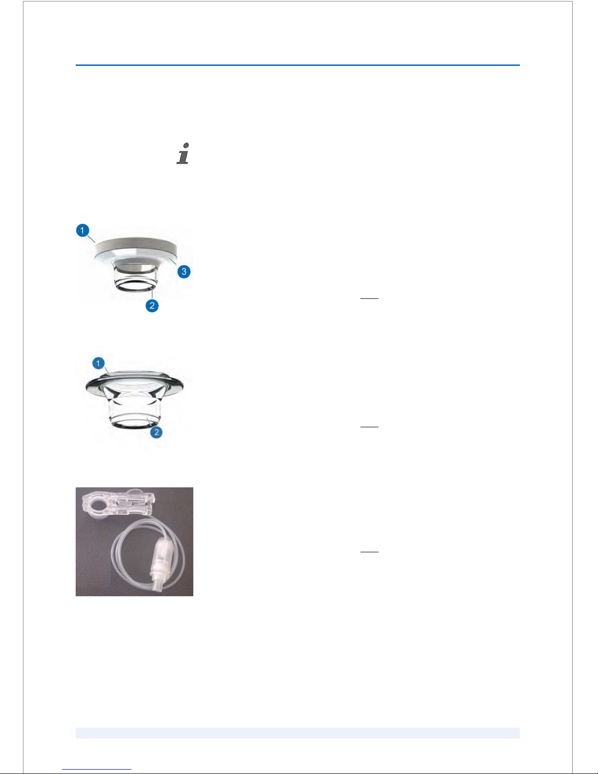
7
Accessories and tools
The Patient Interfaces 125 and the Suction Clips 125 are accessories and the other
items are additional tools.
7.1
Accessories
Patient Interface 125 of the Patient Interface 125 Kit (REF 90000115)
The PI 125 (REF 90000115) must only be used with the VICTUSä Femtosecond
Laser Platform (software version 2.7 and higher).
The PI 125 (REF 90000115) resembles a contact lens. The wider side (1) is sucked
to the spacer cone of the laser system. The smaller side (2) contacts the corneal
surface of the patient's eye.
The product is sterile and for single use
only!
WARNING! Ensure that the PI 125 (REF 90000115) is only used together with the
suction clip (REF 90000115)!
Patient Interface 125 of the Patient Interface 125 Kit (REF 90000145)
The PI 125 (REF 90000145) must only be used with the VICTUSä Femtosecond
Laser Platform (software version 3.3 and higher).
The PI 125 (REF 90000145) resembles a contact lens. The wider side (1) is sucked
to the spacer cone of the laser system. The smaller side (2) contacts the corneal
surface of the patient's eye.
The product is sterile and for single use only!
WARNING! Ensure that the PI 125 (REF 90000145) is only used together with the
suction clip (REF 90000145)!
Suction Clip 125 of the Patient Interface 125 Kit (REF 90000115)
The suction clip (REF 90000115) must only be used with the VICTUSä Femto‐
second Laser Platform (software version 2.7 and higher).
The suction clip (REF 90000115) consists of a suction clip and a tube with a suc‐
tion reservoir.
The product is sterile and for single use only!
WARNING! Ensure that the suction clip (REF 90000115) is only used together
with the PI 125 (REF 90000115)!
ACCESSORIES AND TOOLS
7
SKU: 70005780TPV * Version 6 * UM-100010770 GB
7 - 1
Page 64
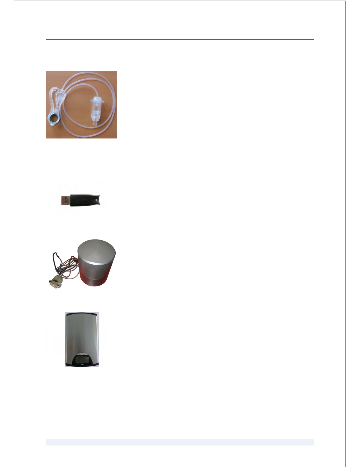
Suction Clip 125 of the Patient Interface 125 Kit (REF 90000145)
The suction clip (REF 90000145) must only be used with the VICTUSä Femto‐
second Laser Platform (software version 3.3 and higher).
The suction clip (REF 90000145) consists of a suction clip and a tube with a suc‐
tion reservoir.
The product is sterile and for single use only!
WARNING! Ensure that the suction clip (REF 90000145) is only used together
with the PI 125 (REF 90000145)!
7.2 Tools
User key
The user key stores and manages licenses for treatment procedures.The user key
uses patented embedded encryption hardware and works exclusively with the
VICTUS™ Femtosecond Laser Platform system software.
Detector head
The detector head is a part of the power meter and is used to perform the power
test.
Digital scale
The digital scale is used to perform the pressure test. It is deliverd with 2 batteries.
ACCESSORIES AND TOOLS
7
SKU: 70005780TPV * Version 6 * UM-100010770 GB
7 - 2
Page 65
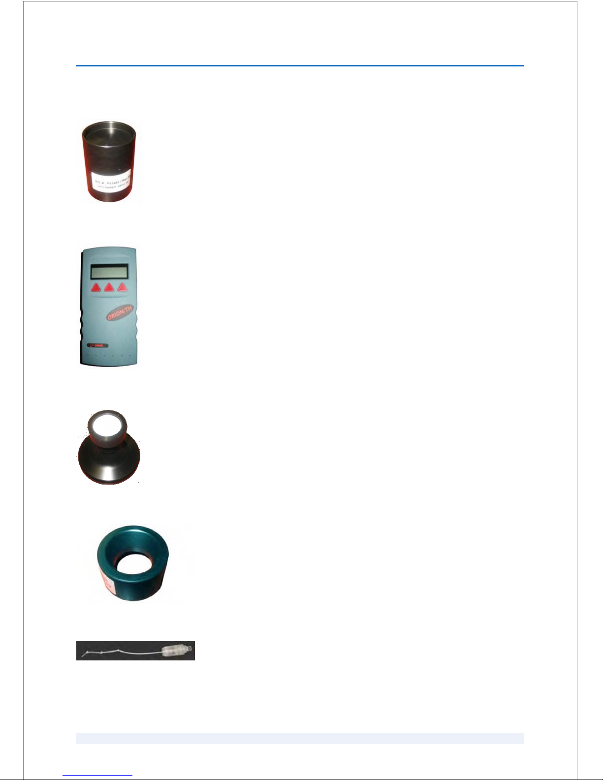
Long adapter
The long adapter is used to perform the depth test.
Power meter
The power meter is used to perform the power test.
Round plate holder
The round plate holder is a holder for the adapters used to perform the pressure
test and the depth test.
Short adapter
The short adapter is used to perform the pressure test.
Suction reservoir
The suction reservoir is used to perform the vacuum test and is inserted into the
suction port of the laser arm.
ACCESSORIES AND TOOLS
7
SKU: 70005780TPV * Version 6 * UM-100010770 GB
7 - 3
Page 66

Support block
The support block is used during all system tests.
ACCESSORIES AND TOOLS
7
SKU: 70005780TPV * Version 6 * UM-100010770 GB
7 - 4
Page 67
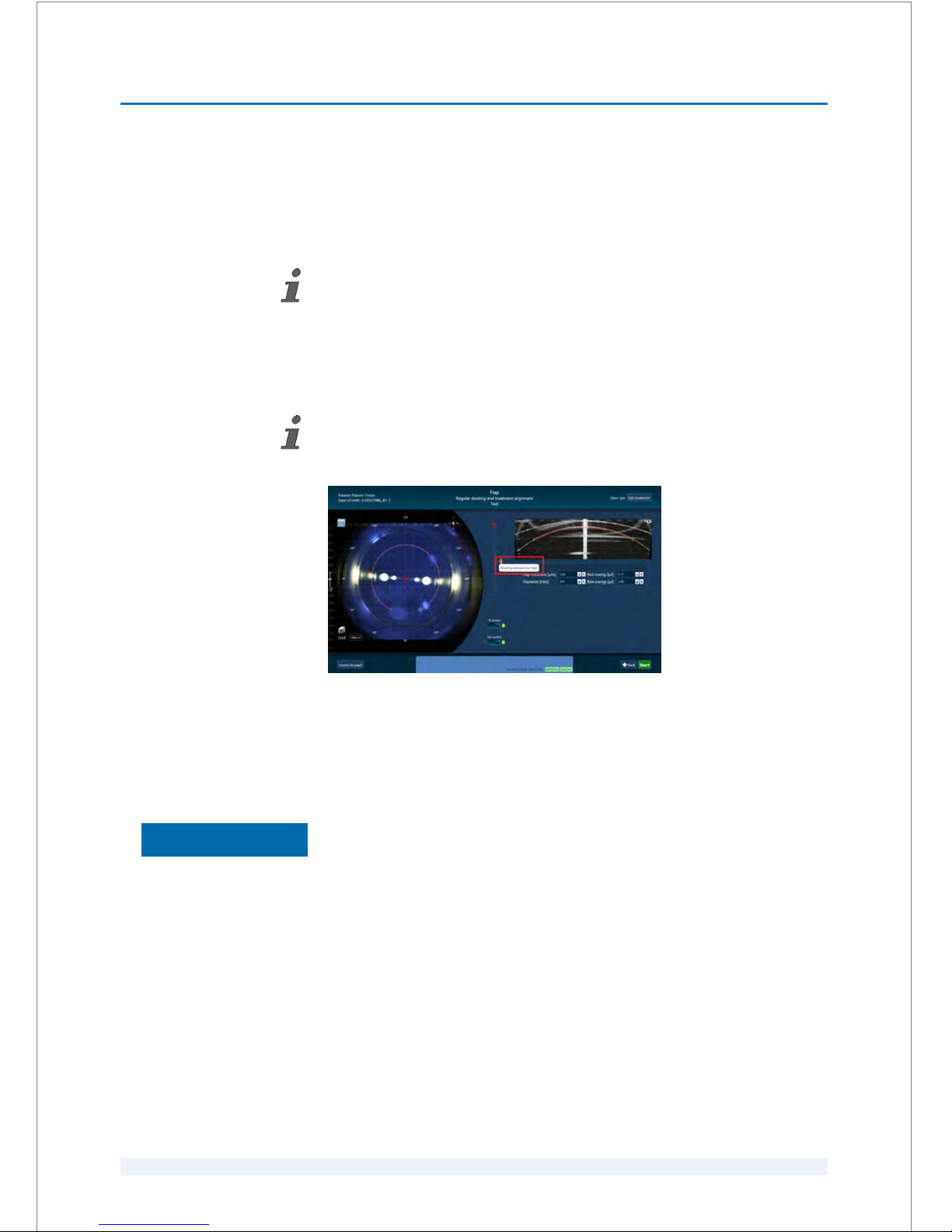
8
Software
8.1
Working with the software
Navigation and editing of elements within the graphical user interface are identical to
a Microsoft
â
Windows operating system.
The laser system software can be operated from either of the two locations:
n Assistant workstation
n Surgeon control screen
The laser system software can be operated and managed by different personnel
(
Ä
Chapter 2.6 ‘Personnel requirements’ on page 2 - 4).
Fig. 20: Error message (example)
Problems are indicated by error messages.
8.1.1
Starting and closing the software
Danger of property damage due to aborted warm-up of the laser system!
The laser system must only be used after the warm-up has been completed.
If you do not allow the laser system to warm up properly, the entire laser
system may be permanently damaged.
– Do not abort warm-up.
–
For initial start-up, wait at least 20 minutes after having turned the
system key to the ‘On’ position. Only after waiting that 20 minutes,
press the blue ‘Reset’ button. After having pressed the ‘Reset’ button,
wait for at least 20 minutes (automatic countdown).
Precondition:
n The laser system and the monitors are switched on (
Ä
Chapter 6.2.3.1
‘Switching the laser system on and off’ on page 6 - 4).
Operating the software
Error messages
Starting the software
NOTICE
SOFTWARE
8
SKU: 70005780TPV * Version 6 * UM-100010770 GB
8 - 1
Page 68
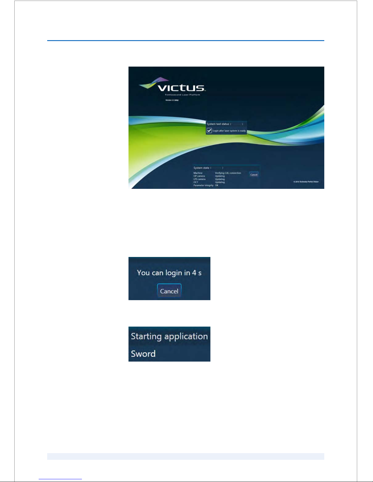
Fig. 21: Startup screen - system test is running
The startup screen appears and the system self test is performed automatically.
The status of the system self test is displayed in the ‘System state’
dialog box
(Fig. 21).
System self test performed successfully:
n If the system self test has been performed successfully, you can login after a
few seconds (Fig. 22).
Fig. 22: System self test performed successfully
After the application has been started (Fig. 23), the login screen appears (Fig. 25).
Fig. 23: Starting application
System self test failed:
n If the system self test failed, the
‘Startup menu’ dialog box appears (Fig. 24).
SOFTWARE
8
SKU: 70005780TPV * Version 6 * UM-100010770 GB
8 - 2
Page 69
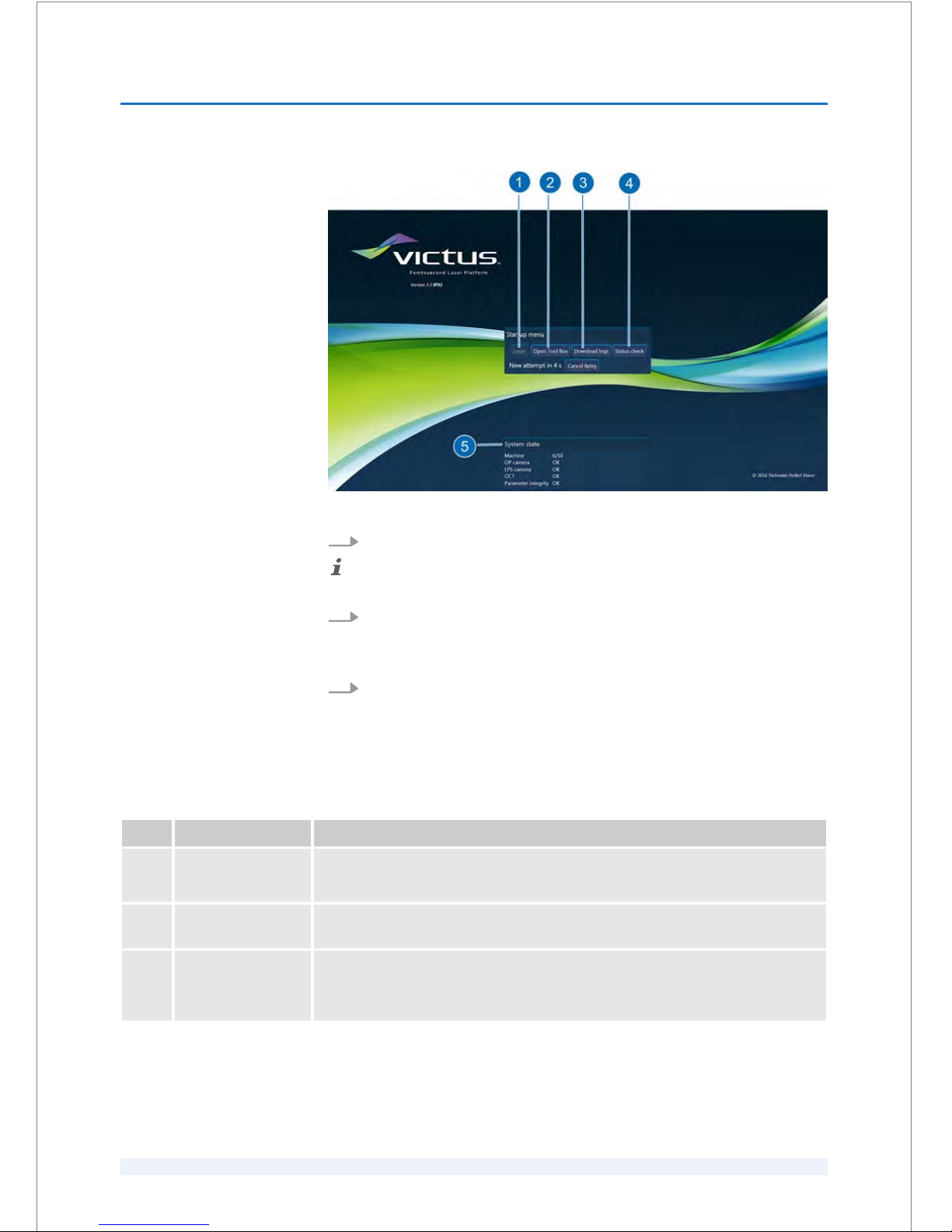
Fig. 24: System self test failed
1.
Click the ‘Status check’ (Fig. 24/4) button to repeat the system self test.
Ensure that a USB memory stick is inserted in the USB port at the start-up panel!
2.
If the system self test fails again, click the ‘Download logs’ button
(Fig. 24/3).
ð
The log files are saved on the USB memory stick.
3.
Contact your local Authorized Service Technician and send the log files.
Once the problem/fault has been rectified and the system self test has been per‐
formed successfully, log in the software (
Ä
‘Log in the software’ on page 8 - 4).
Pos. Button/Field Description
1 ‘Login’ button The ‘Login’ button is disabled.
Click to log in the software once the problem/fault has been rectified.
2 ‘Open Tool Box’
button
Opens the ‘Tool Box’ software to perform troubleshooting, system modifications
and/or adjustments at the laser system by an Authorized Service Technician.
3 ‘Download logs’
button
Click to save the log files on a USB memory stick at the start-up panel. After the log
files have been exported successfully, a message appears.
The log files enable a fast problem/fault diagnosis.
SOFTWARE
8
SKU: 70005780TPV * Version 6 * UM-100010770 GB
8 - 3
Page 70
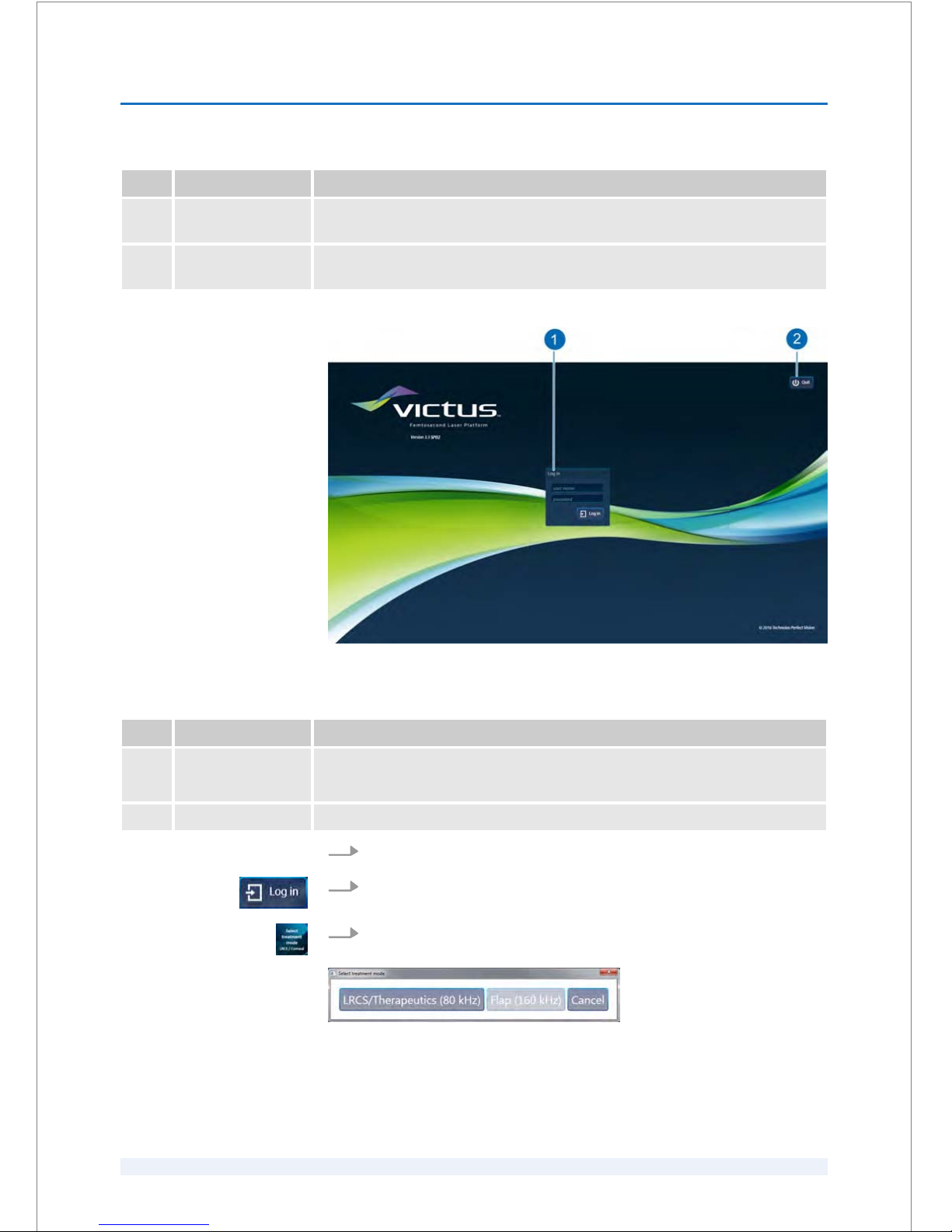
Pos. Button/Field Description
4 ‘Status check’
button
Click to repeat the system self test.
5 ‘System state’
dialog box
Shows the system self test results.
Fig. 25: Login screen
Pos. Button/Field Description
1 ‘user name’ field
‘password’
field
Enter your user name and your password. Click ‘Log in’.
2 ‘Quit’ button Closes the software and leads back to the startup menu.
1.
Type in your user name and password (Fig. 25/1).
2.
Click ‘Log in’.
3.
Click the ‘Select treatment mode LRCS / Corneal’ button (Fig. 27/4), if neces‐
sary.
Fig. 26: ‘Select treatment mode’ screen
ð
The ‘Select treatment mode’ screen (Fig. 26) opens.
Log in the software
SOFTWARE
8
SKU: 70005780TPV * Version 6 * UM-100010770 GB
8 - 4
Page 71
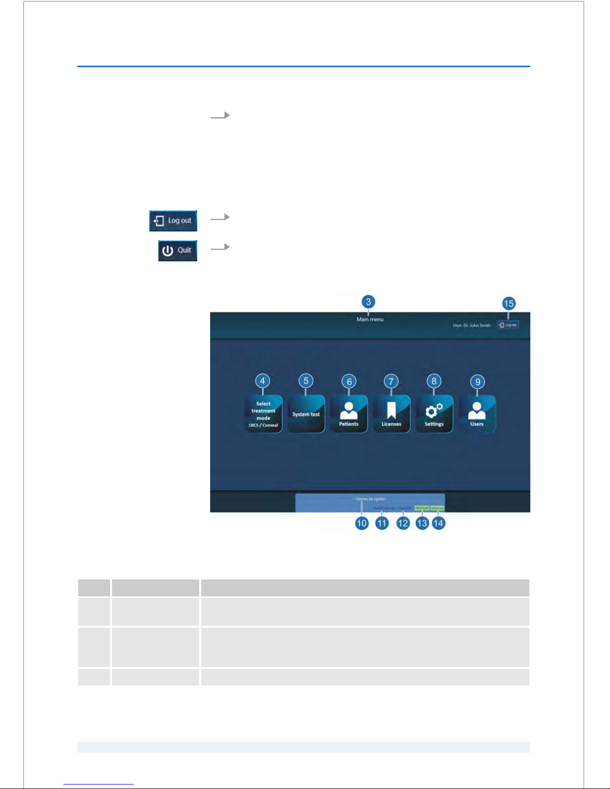
4.
Select ‘LRCS/Therapeutics (80 kHz)’ for cataract or therapeutic treatments, or
‘Flap (160 kHz)’ for flap procedures (Fig. 26).
Precondition:
n The patient bed is underneath the spacer cone.
1.
Click ‘Log out’ (Fig. 27/15).
2.
Then click ‘Quit’ (Fig. 25/2).
8.1.2
Elements of the
‘Main menu’ screen
Fig. 27: Elements of the ‘Main menu’ screen after login (example with ‘Flap (160 kHz)’ )
Pos. Button/Field Description
3 Information header Shows information about the name of the relevant menu or screen, the surgeon's
name, the patient's name, the patient's date of birth and the patient's ID.
4 ‘Select treatment
mode LRCS / Corneal’
button
Opens the ‘Select treatment mode’ screen (refer to Fig. 26).
5 ‘System test’ button Opens the ‘System test’ screen (refer to Fig. 45).
Closing the software
SOFTWARE
8
SKU: 70005780TPV * Version 6 * UM-100010770 GB
8 - 5
Page 72

Pos. Button/Field Description
6 ‘Patients’ button Opens the ‘Patient selection’ screen with the ‘Patients’ and the ‘Treatments’
dialog boxes (refer to Fig. 47).
7 ‘Licenses’ button Opens the ‘Licenses’ screen (refer to Fig. 42).
8 ‘Settings’ button Opens the ‘Settings’ screen (refer to Fig. 40).
9 ‘Users’ button Opens the ‘User management’ screen (refer to Fig. 43).
10 Information field Shows information about what to do in the respective screens or menus.
11 Information field
‘Flap (160 kHz)’
mode
‘LRCS/Therapeutics
(80 kHz)’
mode
Shows information about the selected treatment mode.
12 Information field
‘Pressure’
Shows the actual pressure at the spacer cone.
13 Information field
‘FEMTOCLICK’
Shows whether a user key is connected to the laser system. In this case, the status
field is highlighted green. If not, the status field is highlighted red.
14 Information field
‘System test’
Shows information about the status of the system tests.
15 ‘Log out’ button Logs out the user.
8.1.3
Elements of the treatment screens
The following illustrations show these elements using the flap treatment screens
as an example. The elements are identical for all treatment types. Treatment-spe‐
cific elements are described in
Ä
Chapter 8.1.3.1 ‘Treatment-specific elements’
on page 8 - 11.
SOFTWARE
8
SKU: 70005780TPV * Version 6 * UM-100010770 GB
8 - 6
Page 73
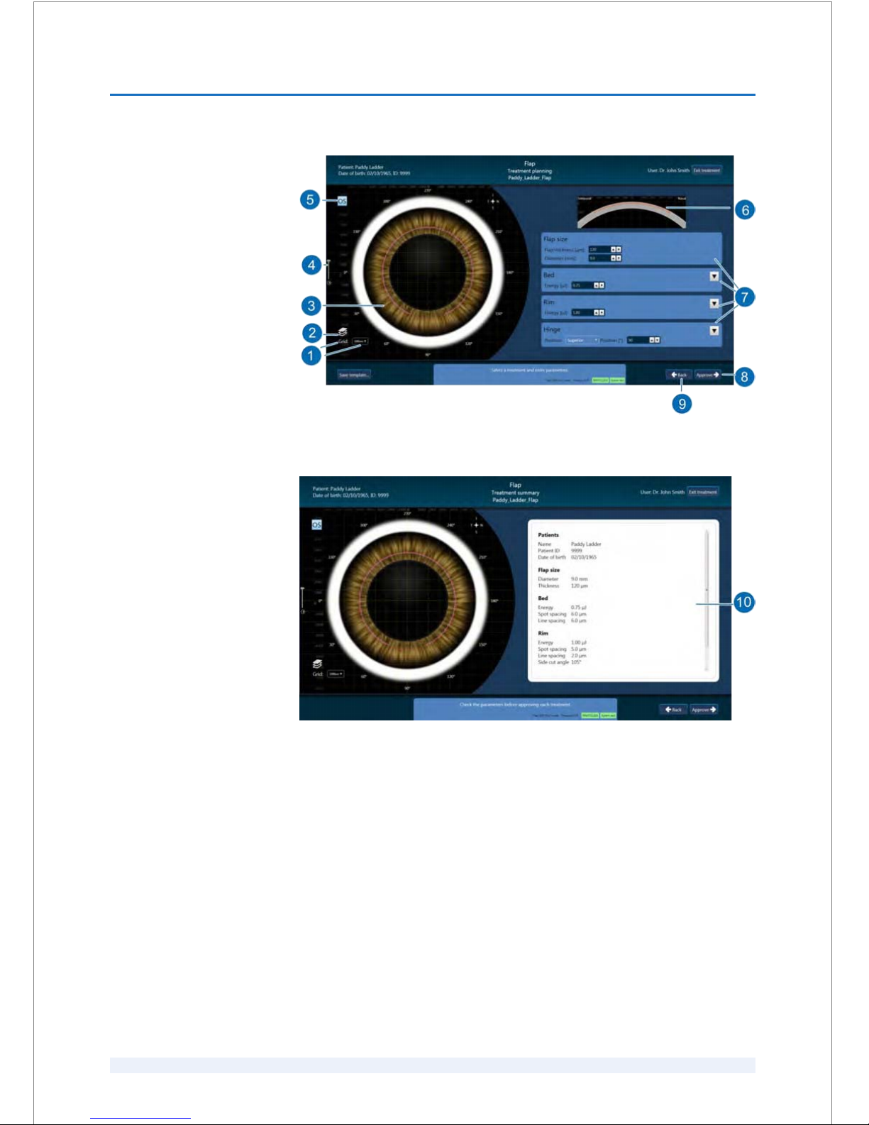
Fig. 28: Elements of the ‘Treatment planning’ screen (example)
Fig. 29: Elements of the ‘Treatment summary’ screen (example)
‘Treatment planning’
screen
‘Treatment summary’
screen
SOFTWARE
8
SKU: 70005780TPV * Version 6 * UM-100010770 GB
8 - 7
Page 74
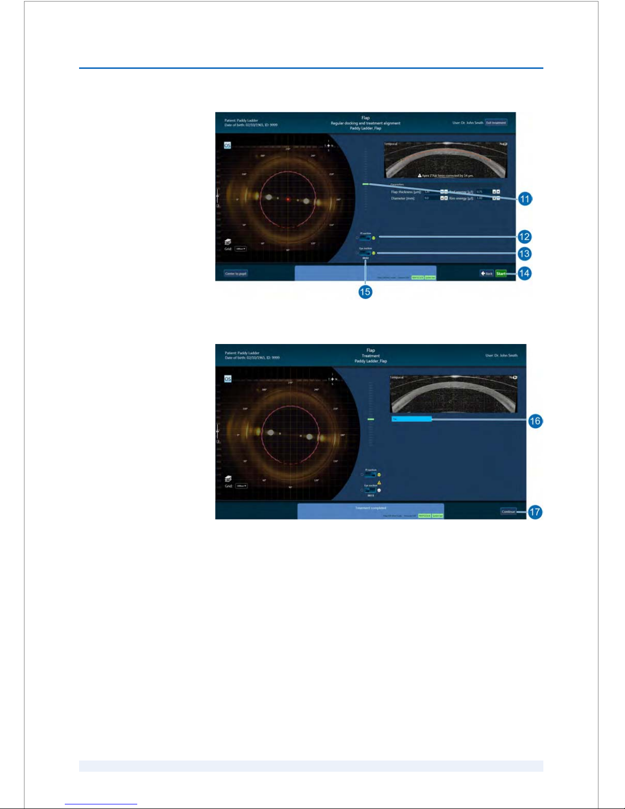
Fig. 30: Elements of the ‘Regular docking and treatment alignment’ screen (example)
Fig. 31: Elements of the ‘Treatment’ screen (example)
‘Regular docking and
treatment alignment’
screen
‘Treatment’ screen
SOFTWARE
8
SKU: 70005780TPV * Version 6 * UM-100010770 GB
8 - 8
Page 75
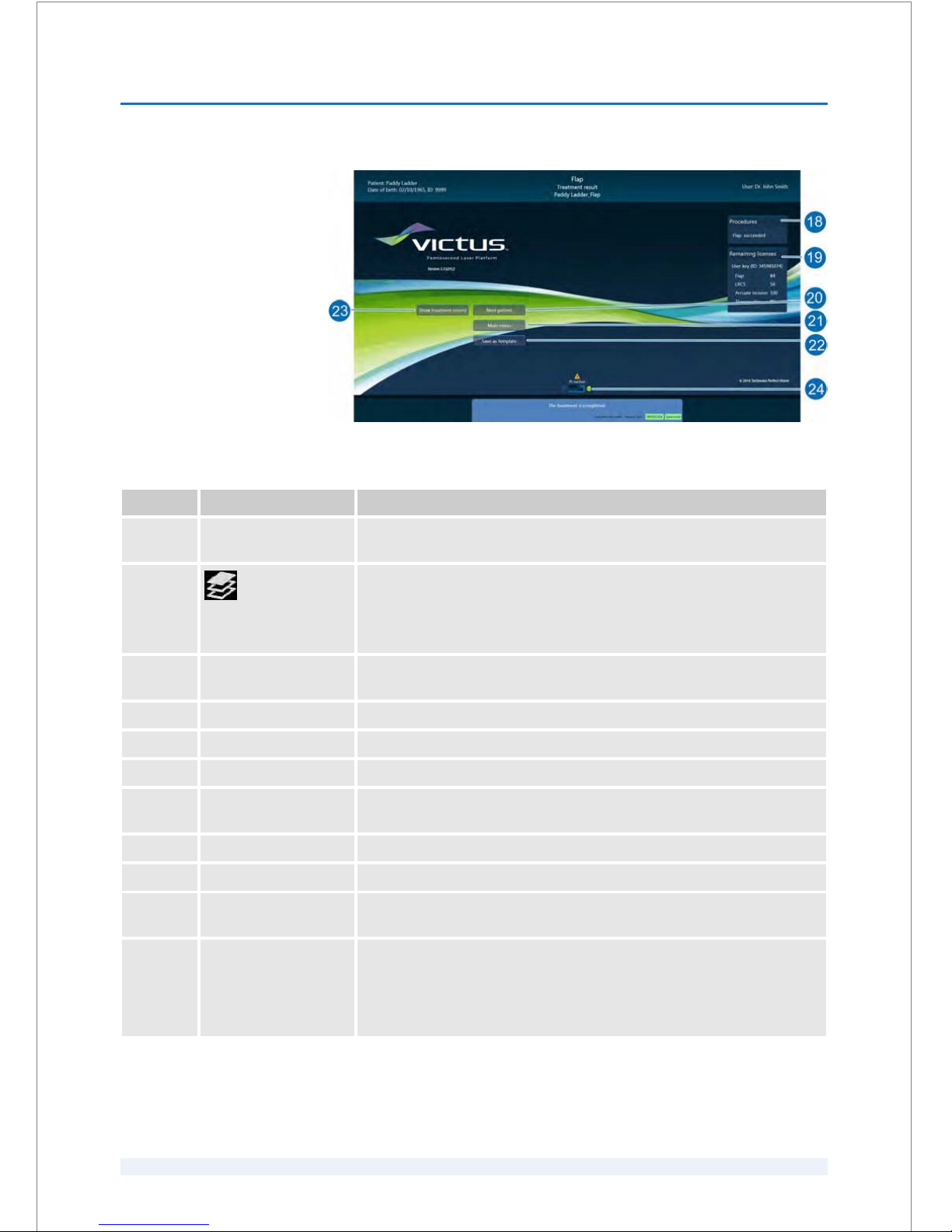
Fig. 32: Elements of the ‘Treatment result’ screen (example)
Pos. Button/Field Description / Action
1 ‘Grid:’ drop-down
selection
Select to fade in or to fade out the grid in the real-time video and have the
choice of different grid patterns.
2
Position / treatment
overlay function
Activates the position overlay / treatment overlay to fade in or to fade out
the schematic presentation of the pupil margin or limbus margin, the
planned cuts/incisions and the circular arrangement in degrees in steps of
30 degrees in the real-time video.
3 Video (live) image First displays a schematic eye image and later on the real-time video of the
patient's eye.
4 Gain slide control Adjusts the illumination contrast in the real-time video via the slide control.
6 ‘OD’ or ‘OS’ Shows the eye that shall be treated.
6 OCT B scan image Shows the real-time OCT B scan image of the patient's eye.
7 Procedure parameters
dialog boxes
Click to view or specify the procedures parameter values.
8 ‘Approve’ button Click to verify the procedures parameter values.
9 ‘Back’ button Click to return to the previous screen.
10 ‘Treatment summary’
overview
Shows a summerized overview about the patient's data and the treat‐
ment's data before starting the treatment.
11 Pressure status display Displays the range of the contact forcing pressure on a scale. This applies to
the regular docking procedures (flap, PKP, LKP, CXL, ICRS, as well as
arcuate incisions and corneal incisions as part of the cataract treatment)
and the docking procedures with reduced applanation pressure for
wrinkle-free docking (capsulotomy and lens fragmentation).
‘Treatment result’ screen
SOFTWARE
8
SKU: 70005780TPV * Version 6 * UM-100010770 GB
8 - 9
Page 76
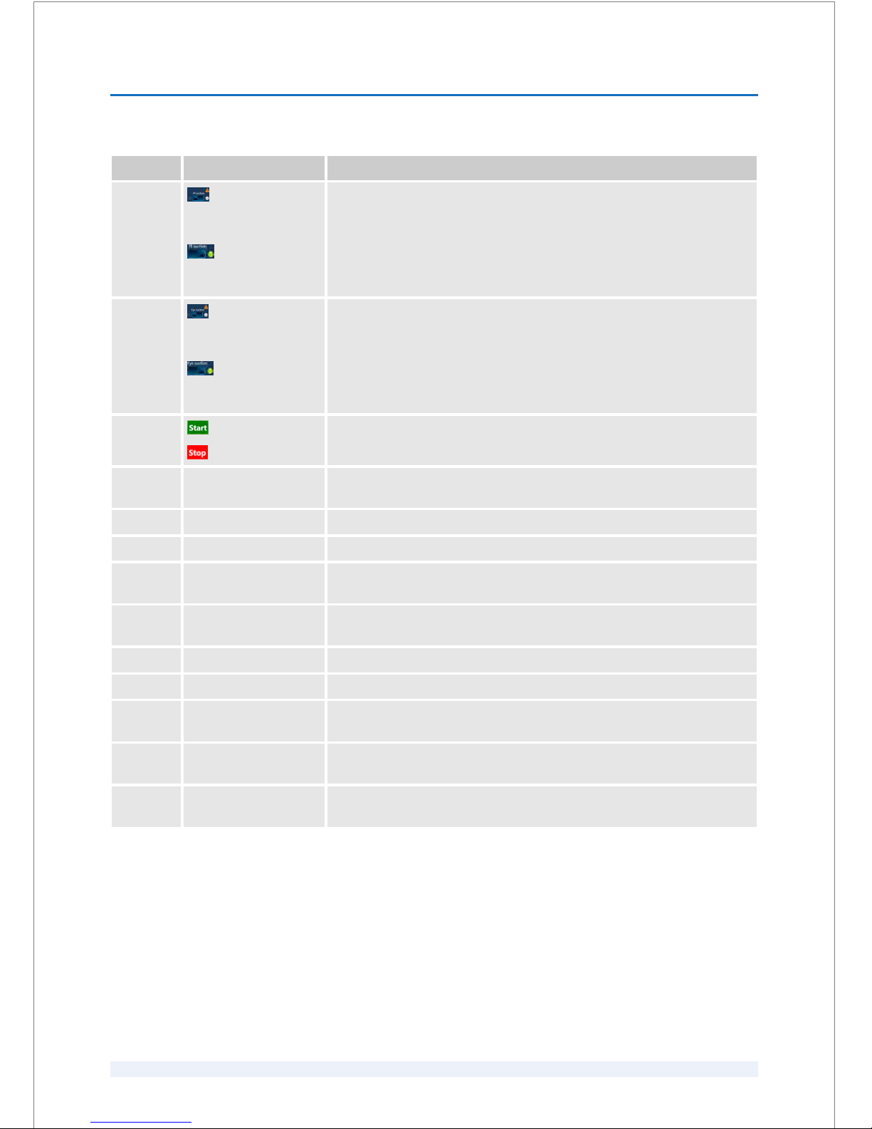
Pos. Button/Field Description / Action
12
‘PI suction’ status
indicator: ‘PI suction’
disabled
‘PI suction’ status
indicator: ‘PI suction’
enabled
Displays the status of the PI suction vacuum.
To enable or disable the PI suction, click the blue button next to the ‘PI
suction’ status indicator.
13
‘Eye suction’ status
indicator:
‘Eye suction’
disabled
‘Eye suction’
status indicator:
‘Eye
suction’ enabled
Displays the status of the eye suction clip vacuum.
To enable or disable the eye suction, click the blue button next to the
‘Eye
suction’ status indicator.
14
‘Start’ button
‘Stop’ button
Click the ‘Start’ button to start a procedure.
Click the ‘Stop’ button to abort a procedure.
15 ‘Eye suction’ timer Starts running after the ‘Eye suction’ is enabled and stops when eye suction
clip vacuum is lost.
16 Treatment progress bar Shows the progress during performing the treatment.
17 ‘Continue’ button Click ‘Continue’ to open the
‘Treatment result’ screen.
18 ‘Procedures’ dialog
box
Shows the treatment results.
19 ‘Remaining licenses’
dialog box
Shows the available/enabled procedures and the respective number of
available licenses.
20 ‘Next patient’ button Click to return to the ‘Patient selection’ screen.
21 ‘Main menu’ button Click to return to the ‘Main menu’ screen.
22 ‘Save as template’
button
Click to save the performed treatment as a template.
23 ‘Show treatment record’
button
Click to show the respective treatment record.
24 ‘PI suction’ enabled
Disables the PI suction (Ä on page 8 - 9/12) after performing the relevant
procedure.
SOFTWARE
8
SKU: 70005780TPV * Version 6 * UM-100010770 GB
8 - 10
Page 77
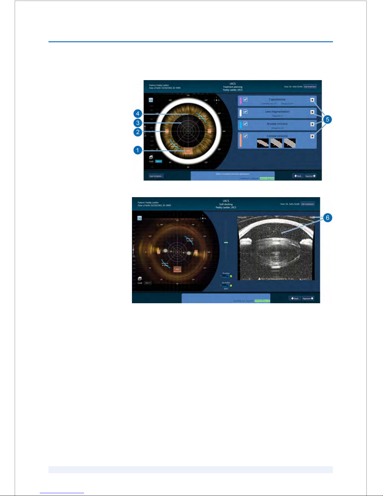
8.1.3.1
Treatment-specific elements
Fig. 33: Elements of the ‘LRCS’ ‘Treatment planning’ screen (example)
Fig. 34: Elements of the ‘LRCS’ ‘Soft docking’ screen (example)
‘LRCS’
SOFTWARE
8
SKU: 70005780TPV * Version 6 * UM-100010770 GB
8 - 11
Page 78
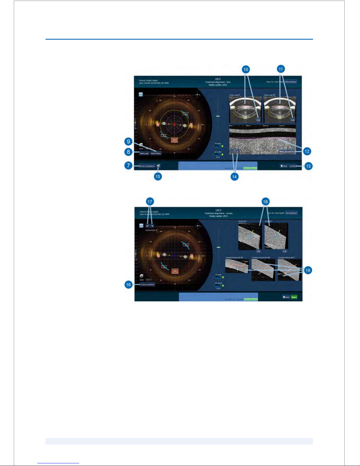
Fig. 35: Elements of the ‘LRCS’ ‘Treatment alignment - lens’ screen (example)
Fig. 36: Elements of the ‘LRCS’ ‘Treatment alignment - cornea’ screen (example)
SOFTWARE
8
SKU: 70005780TPV * Version 6 * UM-100010770 GB
8 - 12
Page 79
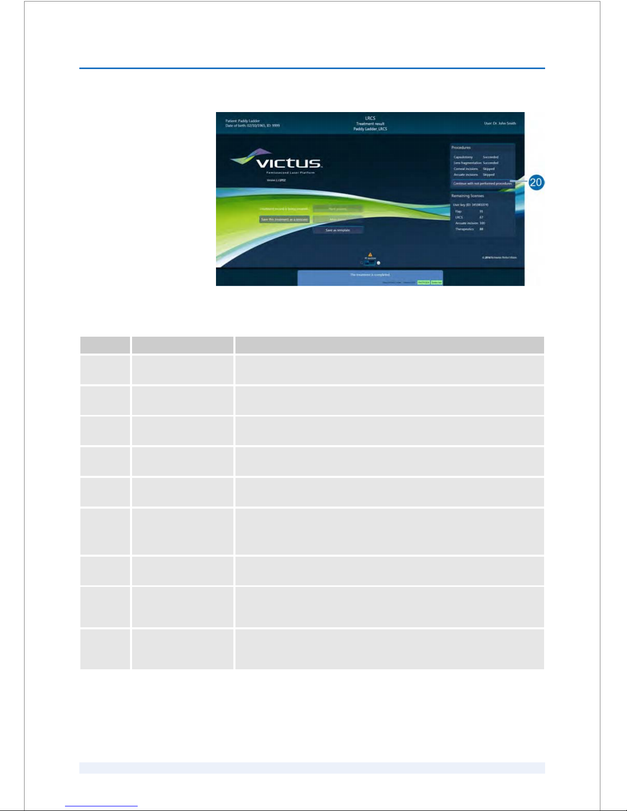
Fig. 37: Elements of the ‘LRCS’
‘Treatment result’ screen (example)
Pos. Button/Field Description / Action
1 Arcuate incisions in the
video (live) image
The schematic presentation of the arcuate incisions is color-coded dis‐
played in the real-time video.
2 Corneal incisions in the
video (live) image
The schematic presentation of the corneal incisions is color-coded dis‐
played in the real-time video.
3 Capsulotomy in the
video (live) image
The schematic presentation of the capsulotomy is color-coded displayed in
the real-time video.
4 Circular/radial cuts in
the video (live) image
The schematic presentation of the circular and/or radial cuts of the lens
fragmentation is color-coded displayed in the real-time video.
5 ‘LRCS’ parameter
values dialog boxes
Open the relevant dialog boxes to view or edit the respective parameter
values.
6 OCT B scan image Shows the real-time OCT B scan image of the patient's eye.
The flashing camera symbol represents the periodical updating of the OCT
B scan image.
7 ‘Restart recognition’
button
To restart the OCT-supported identification of ocular structures, click the
‘Restart recognition’ button.
8 ‘Mark pupil’ button If you do not agree with the results of the automatic identification of the
ocular structures, click the ‘Mark pupil’ button to determine the pupil
margin manually.
9 ‘Mark limbus’ button To center the capsulotomy and the lens fragmentation procedures to the
limbus, click the ‘Mark limbus’ button to determine the limbus margin
manually.
SOFTWARE
8
SKU: 70005780TPV * Version 6 * UM-100010770 GB
8 - 13
Page 80
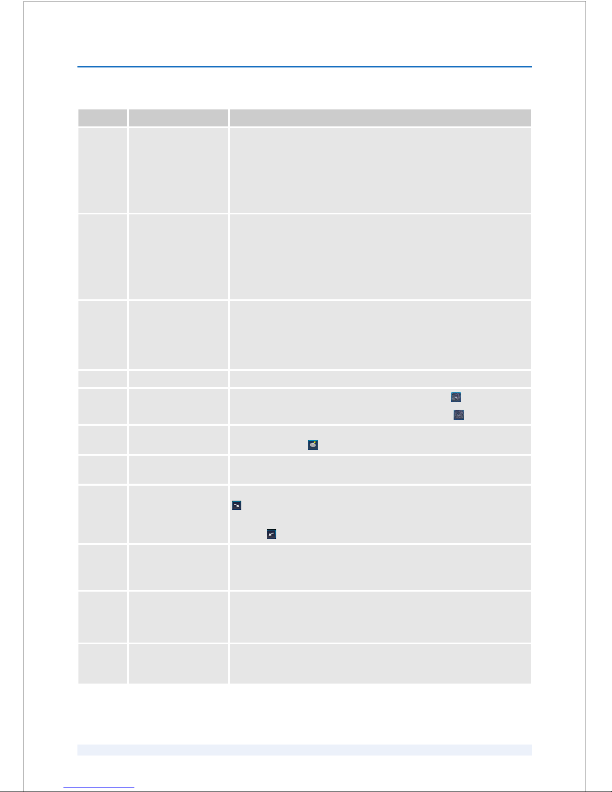
Pos. Button/Field Description / Action
10 ‘Linear scan 0°’ OCT B
scan image
Shows the real-time OCT linear scan image in 0° position of the patient's
eye.
The flashing camera symbol represents the periodical updating of the OCT
B scan image.
Click the ‘Edit’ button to manually mark the anterior lens 0° position and
posterior lens 0° position.
11 ‘Linear scan 90°’ OCT B
scan image
Shows the real-time OCT linear scan image in 90° position of the patient's
eye.
The flashing camera symbol represents the periodical updating of the OCT
B scan image.
Click the ‘Edit’ button to manually mark the anterior lens 90° position and
posterior lens 90° position.
12 Ring scan image Provides depth information of structures in the eye scanned in a circular
manner at the location of the planned capsulotomy.
Click the ‘Mark capsulotomy’ button to mark the highest and lowest point
of the anterior lens surface in the ring scan to ensure a complete capsu‐
lotomy cut.
13 ‘Confirm’ button Click the ‘Confirm’ button to accept all workflow settings.
14 ‘-’ / ‘+’ buttons
To increase the rim height of the capsulotomy, click the button.
To decrease the rim height of the capsulotomy, click the button.
15 ‘Center to lens apex’
button
To center the capsulotomy and the lens fragmentation procedures to the
lens apex, click the button.
16 ‘3-click-centration’
button
To mark the pupil margin, click the ‘3-click-centration’ button.
17 ‘Cyclotorsion’ buttons To rotate the arcuate incisions and the corneal incisions clockwise, click the
button.
To rotate the arcuate incisions and the corneal incisions counterclockwise,
click the button.
18 ‘AI @ 225°’ ‘AI @ 45°’
OCT B scan images
These OCT B scan images show the position of the arcuate incisions.
To adjust the cutting depth of each arcuate incision, click the relevant ‘Edit’
button.
19 ‘Incision @ 90°’ /
‘Incision @ 180°’
/
‘Incision @ 0°’ OCT B
scan images
These OCT B scan images show the cross sections of the cornea where the
corneal incisions are planned.
20 ‘Continue with not
performed procedures’
button
To proceed with skipped procedures, click the ‘Continue with not performed
procedures’ button.
SOFTWARE
8
SKU: 70005780TPV * Version 6 * UM-100010770 GB
8 - 14
Page 81
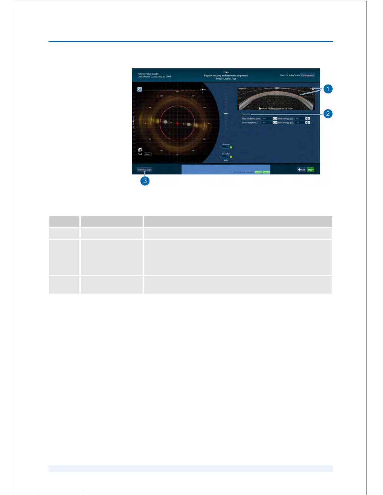
Fig. 38: Elements of the ‘Flap’ ‘Regular docking and treatment alignment’ screen (example)
Pos. Button/Field Description
1 OCT B scan image Shows the real-time OCT B scan image of the patient's eye.
2 ‘Parameters’ dialog
box
Shows flap parameters that can be changed last minute before starting the
procedure.
All other flap parameters are unchangeable at this point. It is only possible
to change these parameters in the respective
‘Treatment planning’ screen.
3 ‘Center to pupil’ button Click the ‘Center to pupil’ button to center the flap automatically to the
center of the pupil as far as possible.
‘Flap’
SOFTWARE
8
SKU: 70005780TPV * Version 6 * UM-100010770 GB
8 - 15
Page 82
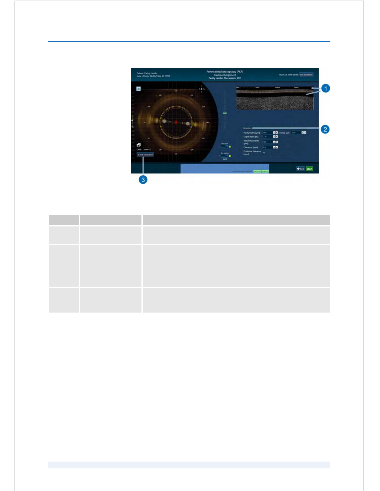
Fig. 39: Elements of the ‘PKP’ ‘Treatment alignment’ screen (example)
Pos. Button/Field Description
1 Ring scan image Shows the real-time OCT ring scan image of the patient's eye at the diam‐
eter of the planned cut.
2 ‘Parameters’ dialog
box
Shows the respective therapeutic parameters that can be changed last
minute before starting the procedure.
All other therapeutics parameters are unchangeable at this point. It is only
possible to change these parameters in the respective
‘Treatment
planning’ screen.
3 ‘3-click-centration’
button
If you do not agree with the results of the automatic identification of the
ocular structures, click the ‘3-click-centration’ button to determine the
pupil margin or the limbus margin manually.
‘Therapeutics’
SOFTWARE
8
SKU: 70005780TPV * Version 6 * UM-100010770 GB
8 - 16
Page 83
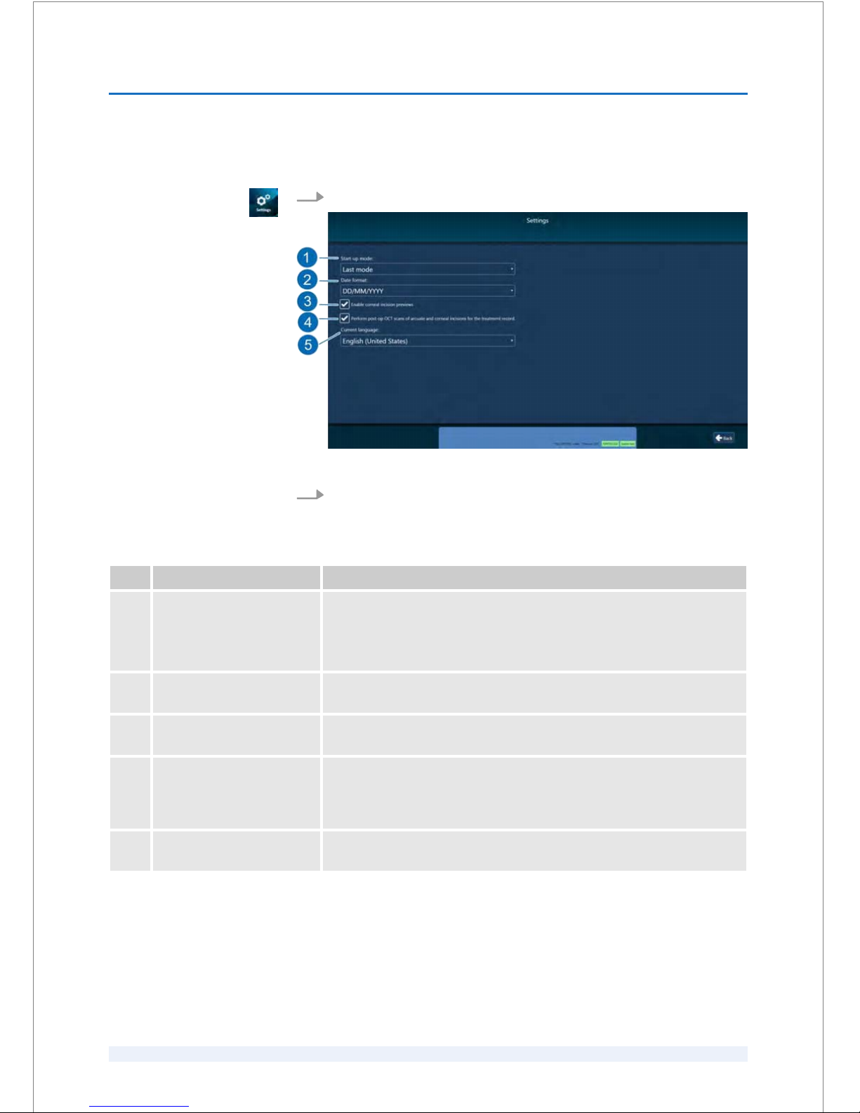
8.1.4
Checking and modifying common settings
1.
Click the ‘Settings’ button (Fig. 27/8) in the
‘Main menu’ screen.
Fig. 40: ‘Settings’ screen
2.
Manage the general settings as described in the following table.
Pos. Name Description
1 ‘Start-up mode:’ drop-down
selection
Select the treatment mode for starting up the laser system.
You can select ‘LRCS/Therapeutics (80 kHz)’ for cataract or therapeutic treat‐
ments, ‘Flap (160 kHz)’
for flap procedures or ‘Last mode’ for starting up the
laser system in the treatment mode that was last used.
2 ‘Date format:’ drop-down
selection
Select the date format that applies to the patient data and treatment data.
3 ‘Enable corneal incision
previews’ check box
Activate this check box to enable or to disable the OCT B scan images of
the corneal incisions during the treatment.
4 ‘Perform post-op OCT scans
of arcuate and corneal
incisions for the treatment
record.’
check box
Activate this check box to perform post-op OCT scans of arcuate incisions
and corneal incisions for the treatment record.
5 ‘Current language:’ drop-
down selection
Select the user interface language.
SOFTWARE
8
SKU: 70005780TPV * Version 6 * UM-100010770 GB
8 - 17
Page 84
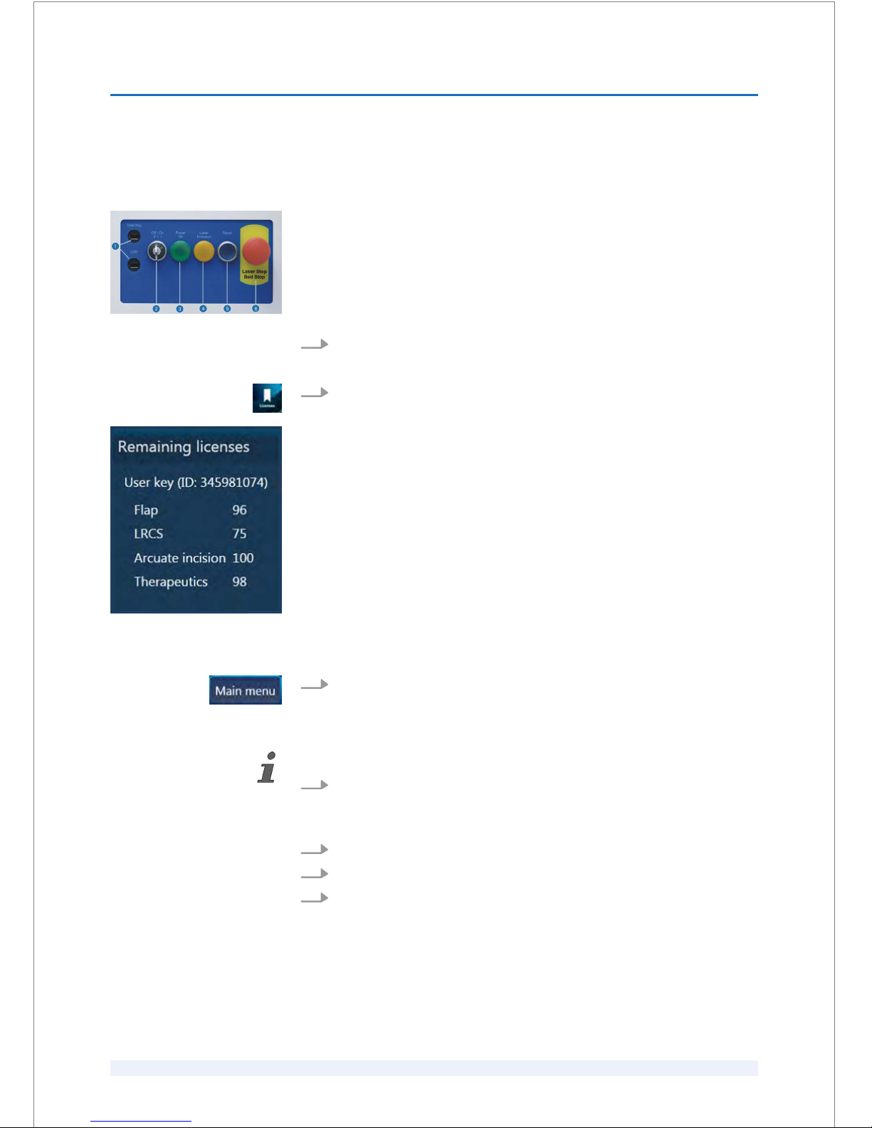
8.1.5
Checking treatment licenses
Special tool:
n
User key
1.
Insert the user key in the
‘User Key’ port (Fig. 41/1) at the start-up panel of
the laser system.
2.
Click the ‘Licenses’ button on the
‘Main menu’ screen (Fig. 27/7).
ð
The ‘Remaining licenses’ dialog box (Fig. 42) shows the available/ena‐
bled procedures and the respective number of available licences.
3.
To close the
‘Licenses’ screen, click the‘Main menu’ button.
8.1.6
Restarting the software after an emergency shutdown
Ensure that no patient or equipment are attached to the spacer cone!
1.
If required, undock the patient or the equipment and click ‘Confirm’.
ð
The software will shut down. Wait for the forced shutdown to close all
programs.
2.
Press the
‘Reset’ button (Fig. 41/5) at the start-up panel.
3.
Wait for approximately 30 minutes until the reconnection is completed.
4.
Continue as described in
Ä
Chapter 8.1.1 ‘Starting and closing the software’
on page 8 - 1.
Fig. 41: Start-up panel - ‘User Key’ port
Fig. 42: ‘Licenses’ screen / ‘Remaining
licenses’ dialog box
SOFTWARE
8
SKU: 70005780TPV * Version 6 * UM-100010770 GB
8 - 18
Page 85

8.2 User administration
8.2.1
User profiles and specific rights
‘User’ ‘Admin’
Perform system tests (
Ä
Chapter 8.3 ‘System test descrip‐
tion’ on page 8 - 21)
3
Check ‘FEMTOCLICK’ licenses (
Ä
Chapter 8.1.5 ‘Checking
treatment licenses’ on page 8 - 18)
3 3
View patient data
3
Add new patients (
Ä
Chapter 8.4.1 ‘Adding patients’
on page 8 - 24)
3
Edit patient data (
Ä
Chapter 8.4.3 ‘Editing patient data’
on page 8 - 26)
3
Delete patient data (
Ä
Chapter 8.4.4 ‘Deleting patient
data’ on page 8 - 26)
3
View treatments
3
Create new treatments (
Ä
Chapter 8.4.6 ‘Creating treat‐
ments’ on page 8 - 28)
3
Edit treatment data (
Ä
Chapter 8.4.7 ‘Editing treatments’
on page 8 - 32)
3
Delete treatment data (
Ä
Chapter 8.4.8 ‘Deleting treat‐
ments’ on page 8 - 32)
3
View user data
3
Add new users (
Ä
Chapter 8.2.2 ‘Adding users’
on page 8 - 20)
3
Edit registered user accounts (
Ä
Chapter 8.2.3 ‘Editing
registered user accounts’ on page 8 - 21)
3
Reset passwords
3
Execute procedures (
Ä
Chapter 9 ‘Treatment’
on page 9 - 1)
3
SOFTWARE
8
SKU: 70005780TPV * Version 6 * UM-100010770 GB
8 - 19
Page 86
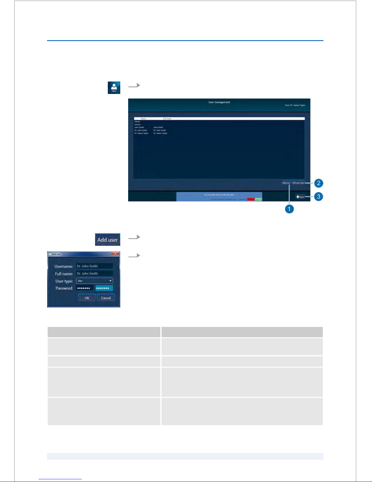
8.2.2
Adding users
1.
On the main screen, click the ‘Users’ button (Fig. 27/9) to open the
‘User
management’ screen (Fig. 43).
Fig. 43: ‘User management’ screen (example)
2.
To add a new user, click the ‘Add user’ button (Fig. 43/1).
3.
Enter the user data in the mandatory fields of the ‘Add user’ dialog box
(Fig. 44) and add the corresponding user profile to the user.
Field Description
‘Username:’ Specifies the user name for login (minimum 6 characters).
Mandatory.
‘Full name:’ Specifies the user's full name. Mandatory.
‘User type:’
n ‘Admin’
n ‘User’
Shows the registered user profiles.
Select the corresponding user profile for the new user.
‘Password:’ Specifies the user's password (minimum 6 characters).
Mandatory.
To confirm, enter the password twice.
Fig. 44: ‘Add user’ dialog box
SOFTWARE
8
SKU: 70005780TPV * Version 6 * UM-100010770 GB
8 - 20
Page 87
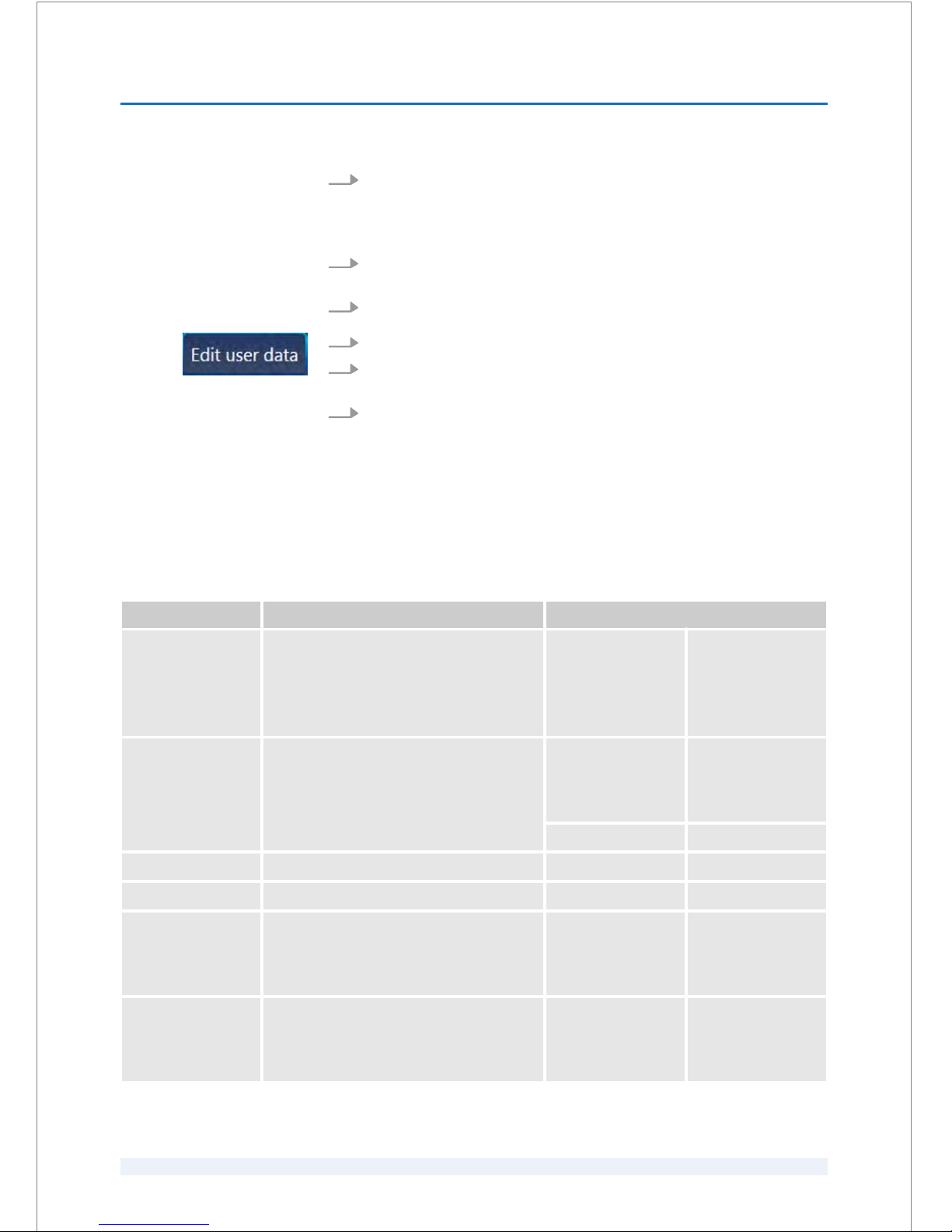
4.
Click the ‘OK’ button to save the new user account.
8.2.3
Editing registered user accounts
1.
On the
‘Main menu’ screen, click the ‘Users’ button (Fig. 27/9) to open the
‘User management’ screen (Fig. 43).
2.
Click the user account that you want to edit.
3.
To edit the data, click the ‘Edit user data’ button (Fig. 43/2).
4.
View or specify the corresponding user record data in the
‘Add user’ dialog
box (Fig. 44).
5.
Click the ‘OK’ button.
8.3
System test description
The system tests include the functionality test for system components, the ‘Laser
position test’ and four startup tests that the user must perform manually.
‘System test’ overview
System test Explanation Performing the system test:
Functionality test
(chiller)
The laser system automatically performs a
system self test regarding the functionality
of the system components.
The results of the functionality test for the
chiller are displayed on the ‘Chiller’ screen.
automatically
n after the laser
system has been
switched on
‘Laser position test’ The laser position sensor (LPS) checks the
proper function of the laser scanner mirrors,
as well as the integrity and precision of the
proper alignment of the whole optical
system.
manually
n daily
n after a treatment
mode has been
changed
automatically after each treatment
‘Vacuum test’ Startup test manually
n daily
‘Pressure test’ Startup test manually
n daily
‘Depth test’ Startup test manually
n daily
n after a treatment
mode has been
changed
‘Power test’ Startup test manually
n daily
n after a treatment
mode has been
changed
SOFTWARE
8
SKU: 70005780TPV * Version 6 * UM-100010770 GB
8 - 21
Page 88
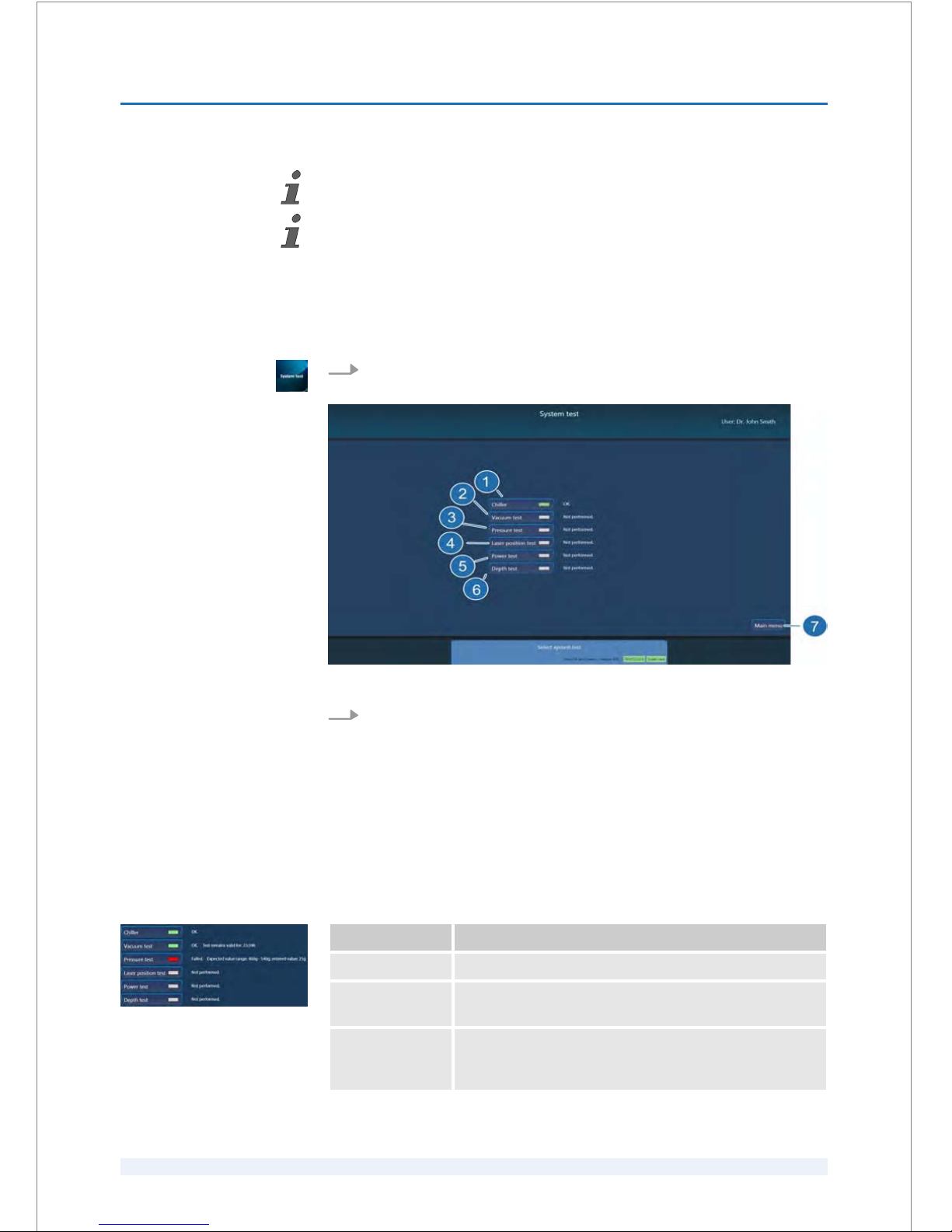
The result of each system test is displayed in the ‘System test’ screen next to the rele‐
vant status indicator (Fig. 46).
Performing the ‘System test’
How to perform these system tests is described in the
Ä
Chapter 9.3 ‘Performing the
daily system test’ on page 9 - 2.
1.
Click the ‘System test’ button on the
‘Main menu’ screen (Fig. 27/5) to open
the ‘System test’ screen (Fig. 45).
Fig. 45: ‘System test’ screen
2.
Click the relevant button (Fig. 45) to open the dialog box for the associated
system test screen.
You can proceed as folllows:
n Perform the
‘Laser position test’
n Perform the startup tests
n Verify the results of the automatic functionality test for the chiller.
Status indicator Explanation
gray System test has not been performed yet.
green Test parameters are within the acceptable range. You can
proceed with the next test or procedure.
red A system error has occured. You will not be able to start
with the procedure. Contact an Authorized Service
Technician.
Opening the ‘System test’
screen
Status indicators
Fig. 46: ‘System test’ status indicators
SOFTWARE
8
SKU: 70005780TPV * Version 6 * UM-100010770 GB
8 - 22
Page 89
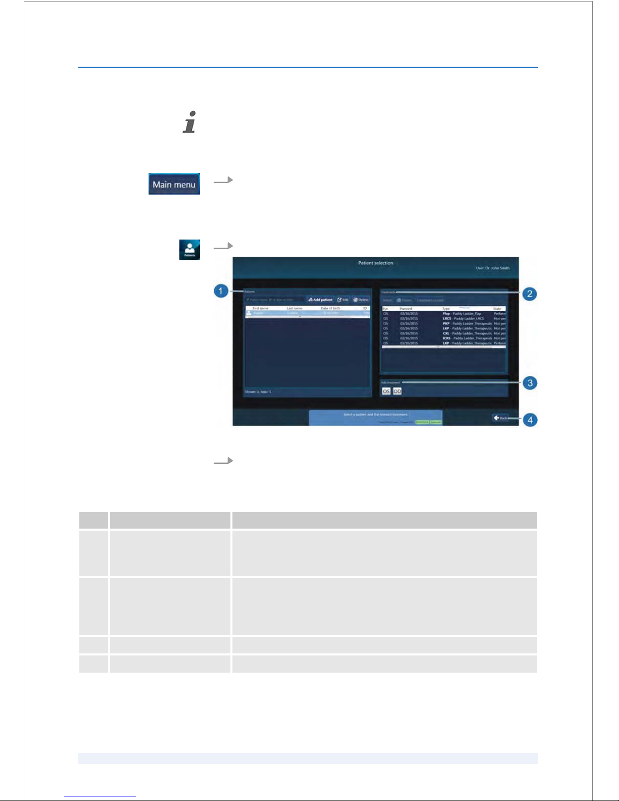
After a successful system test, all status indicators have turned green.
Click the ‘Main menu’ button (Fig. 45/7).
8.4
Patient / treatment administration
1.
Click the ‘Patients’ button (Fig. 27/6) in the
‘Main menu’ screen.
Fig. 47: ‘Patient selection’ screen
2.
Manage the patients and treatments as described in the following table.
Pos. Name Description
1 ‘Patients’ dialog box Manage patient data.
You can select patient data, create new patient records, modify or delete
patient data.
2 ‘Treatments’ dialog box Manage patient data.
You can select treatment records, modify or delete data in selected treat‐
ment records. If treatments have already been performed, the treatment
records can be viewed.
3 ‘Add treatment’ dialog box Create new treatments.
4 ‘Back’ button Return to the ‘Main menu’ screen.
Closing the ‘System test’
SOFTWARE
8
SKU: 70005780TPV * Version 6 * UM-100010770 GB
8 - 23
Page 90
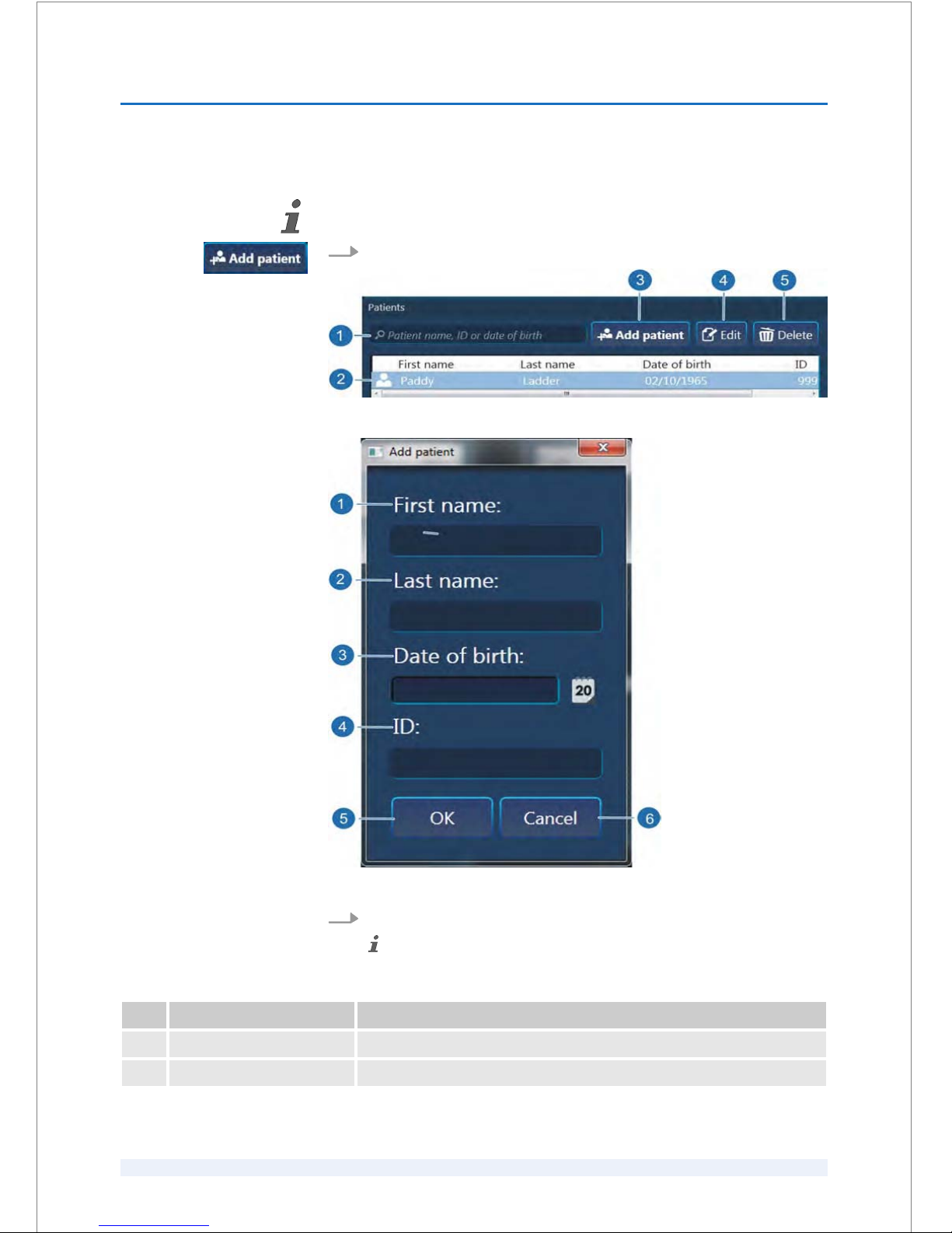
8.4.1
Adding patients
The ‘Patients’ dialog box must be opened (Fig. 47/1) in the ‘Patient selection’ screen.
1.
To add a new patient, click ‘Add patient’ (Fig. 48/3).
Fig. 48: ‘Patients’ dialog box
Fig. 49: ‘Add patient’ dialog box
2.
Enter the patient data (
Ä
Table on page 8 - 24) in the fields described below:
All (mandatory) fields must be filled in, otherwise the ‘OK’ button will not be
enabled.
Pos. Field Name Description
1 ‘First name:’ Specifies the patient's first name.
2 ‘Last name:’ Specifies the patient's last name.
SOFTWARE
8
SKU: 70005780TPV * Version 6 * UM-100010770 GB
8 - 24
Page 91

Pos. Field Name Description
3 ‘Date of birth:’ Specifies the patient's date of birth (format: MM/DD/YYYY).
4 ‘ID:’ Specifies the patient's ID as alphanumeric string.
The entry in the
‘ID:’ field must be unique!
5 ‘OK’ button Click the ‘OK’ button to save all patient data.
6 ‘Cancel’ button Click the ‘Cancel’ button, if you do not want to save the patient data.
3.
To save the new patient data, click the ‘OK’ button.
ð
The new patient is added to the database.
8.4.2
Selecting patients
The ‘Patients’ dialog box must be opened (Fig. 47/1) in the ‘Patient selection’ screen.
1.
To search for a specific patient, enter at least the first characters of the
patient's first name, last name, date of birth or identifier in the search box
(Fig. 48/1) of the ‘Patients’ dialog box.
ð
The search result is highlighted (Fig. 48/2).
2.
Click in the row with the patient that you want to select.
ð
The treatments assigned to the selected patient are displayed in the
‘Treatments’ dialog box (Fig. 47/2).
SOFTWARE
8
SKU: 70005780TPV * Version 6 * UM-100010770 GB
8 - 25
Page 92
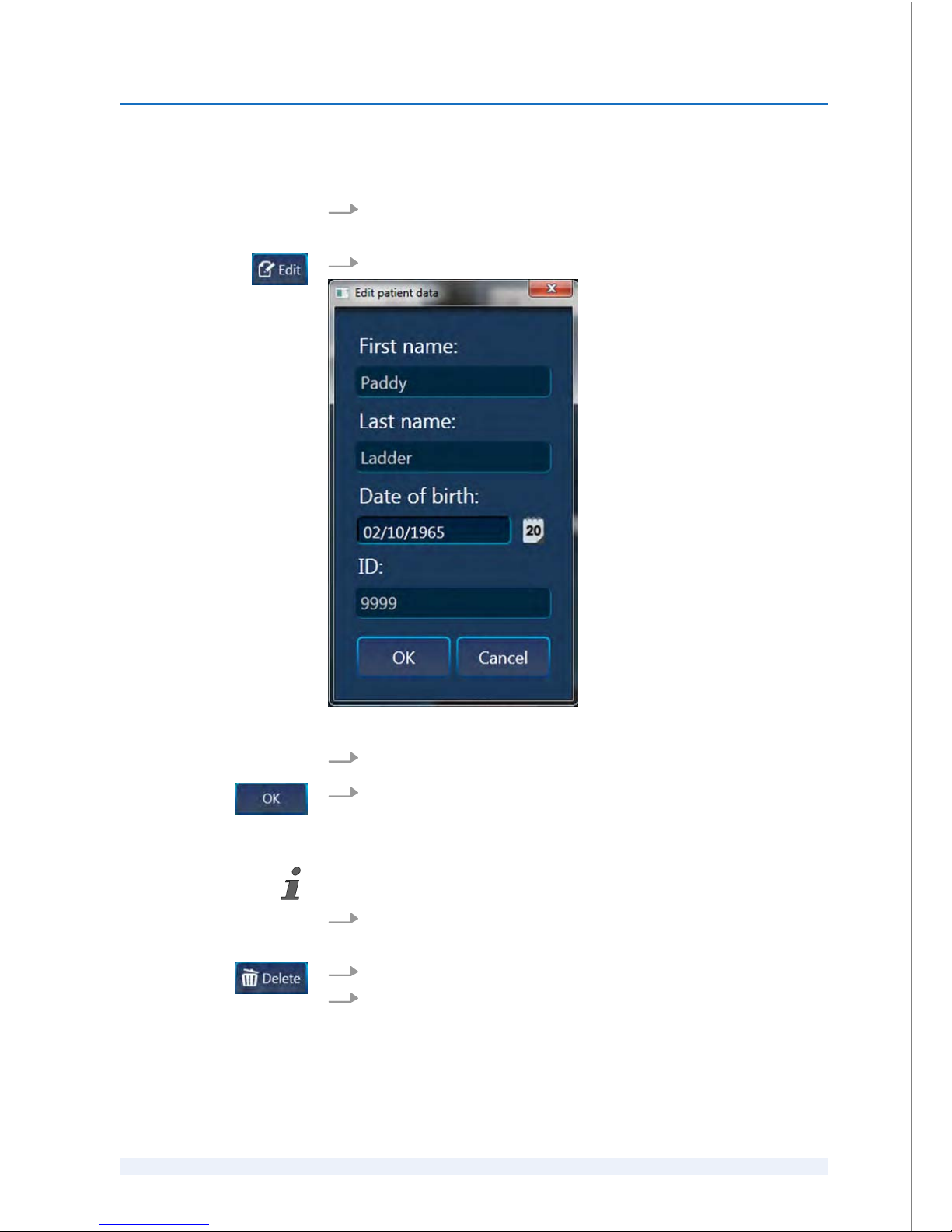
8.4.3
Editing patient data
1.
Select a patient as described in
Ä
Chapter 8.4.2 ‘Selecting patients’
on page 8 - 25.
2.
Click the ‘Edit’ button (Fig. 48/4) to open the corresponding dialog box.
Fig. 50: ‘Edit patient data’ dialog box
3.
View or edit the corresponding patient data (Fig. 50).
4.
Click the ‘OK’ button to apply any changes.
8.4.4
Deleting patient data
Only data from patients, who have not been treated yet, may be deleted.
1.
Select the patient that you want to delete as described in
Ä
Chapter 8.4.2
‘Selecting patients’ on page 8 - 25.
2.
Click the ‘Delete’ button (Fig. 48/5).
3.
To delete the patient data, confirm with ‘Yes’ in the warning message.
SOFTWARE
8
SKU: 70005780TPV * Version 6 * UM-100010770 GB
8 - 26
Page 93
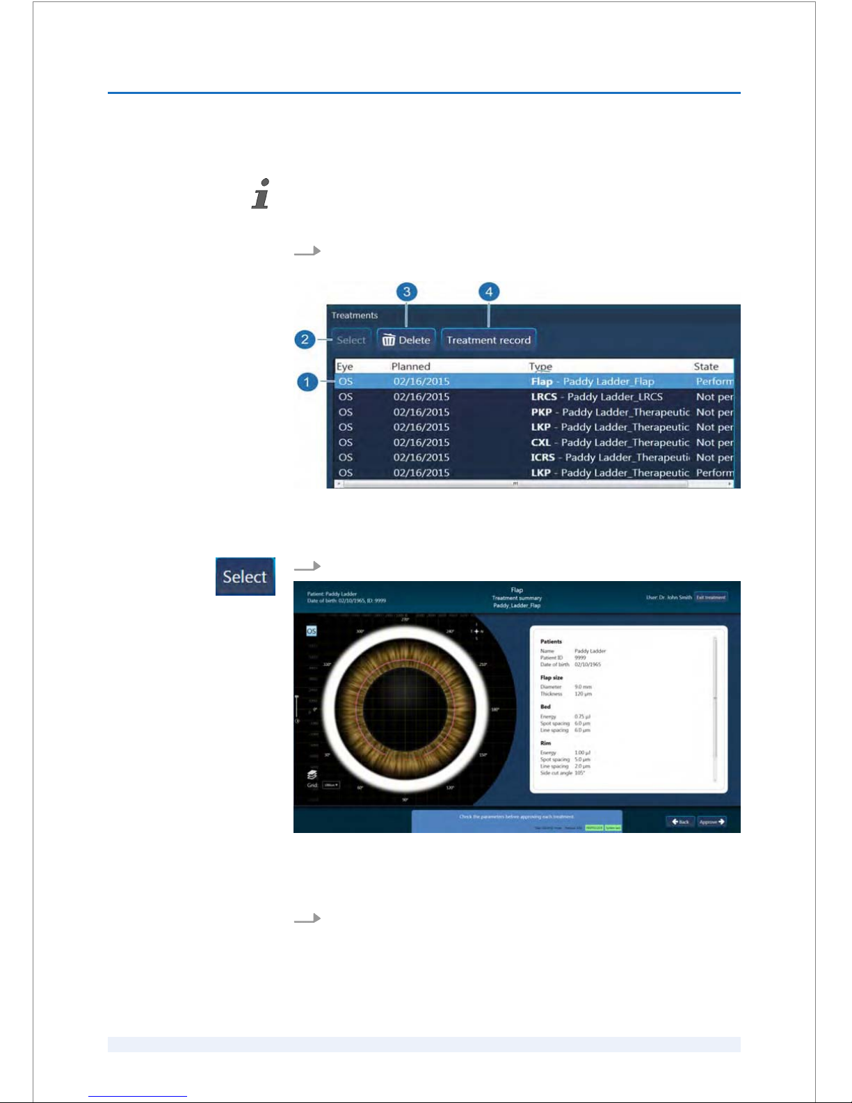
8.4.5
Selecting treatments for execution
Precondition:
A patient must be selected as described in
Ä
Chapter 8.4.2 ‘Selecting patients’
on page 8 - 25.
1.
To select a treatment in the
‘Treatments’ dialog box (Fig. 47/2), click on the
row with the appropriate treatment.
Fig. 51: ‘Treatments’ dialog box
ð
The selected treatment is highlighted (Fig. 51/1).
2.
Click the ‘Select’ button (Fig. 51/2).
Fig. 52: ‘Treatment summary’ screen (example)
ð
The ‘Treatment summary’ screen (Fig. 52) opens. So you can verify the
parameter values before starting the treatment.
3.
Continue with Ä Chapter 9 ‘Treatment’ on page 9 - 1.
SOFTWARE
8
SKU: 70005780TPV * Version 6 * UM-100010770 GB
8 - 27
Page 94
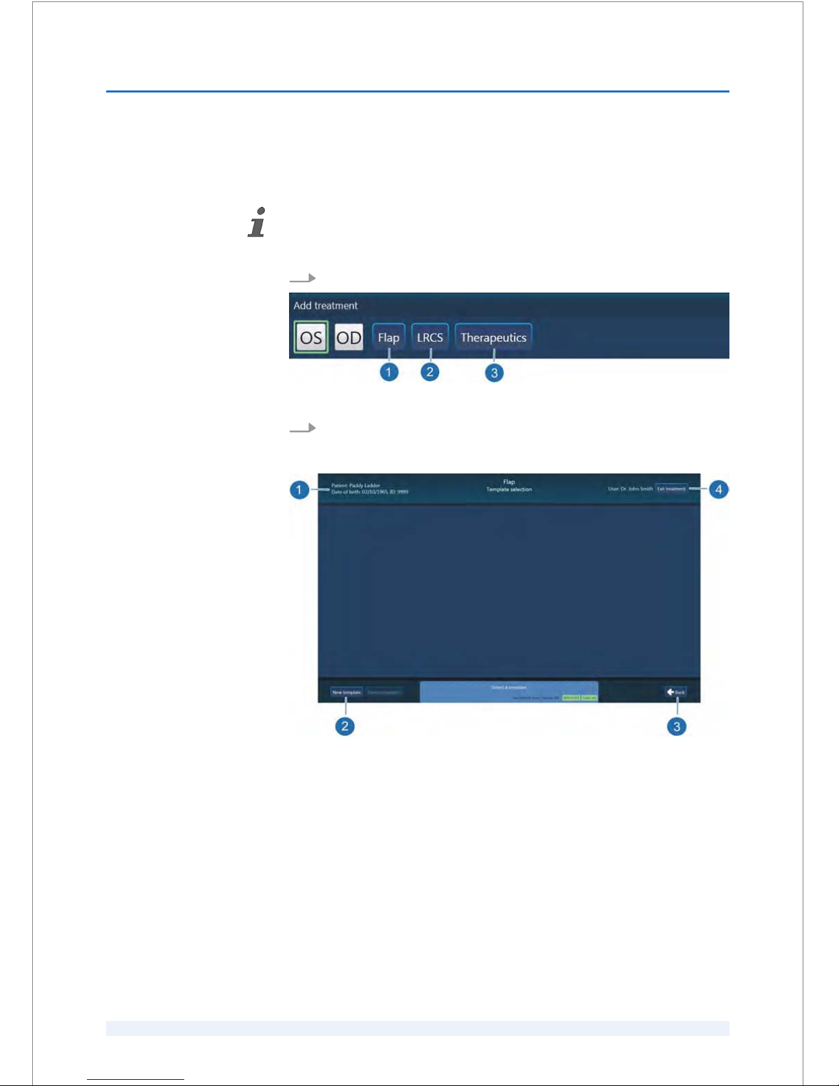
8.4.6
Creating treatments
Precondition:
A patient must be selected as described in
Ä
Chapter 8.4.2 ‘Selecting patients’
on page 8 - 25.
1.
Click the ‘OD’ or ‘OS’ button (Fig. 47/3).
Fig. 53: ‘Add treatment’ dialog box
2.
Select ‘Flap’ (Fig. 53/1) to create a flap procedure, ‘LRCS’ (Fig. 53/2) to
create a cataract treatment or ‘Therapeutics’ (Fig. 53/3) to create a thera‐
peutic treatment.
Fig. 54: ‘Flap’ ‘Template selection’ screen (example)
ð
The
‘Template selection’ screen (Fig. 54) opens to create a new treat‐
ment based on determined parameter default values or on a desig‐
nated template.
SOFTWARE
8
SKU: 70005780TPV * Version 6 * UM-100010770 GB
8 - 28
Page 95

The following table describes the relevant screens for the treatment selection and
the treatment planning.
Pos. Name Description
Fig. 54
1 ‘Template selection’ screen
header
Shows information about the selected patient, the user (surgeon) and if
designated, the template's name.
2 ‘New template’ button Creates new treatment templates based on determined parameter default
values or on a designated template.
3 ‘Back’ button Returns to the ‘Patient selection’ screen.
4 ‘Exit treatment’ button Closes a treatment.
Fig. 55
5 ‘Default’ button Creates a new treatment template based on determined parameter default
values.
6 Designated template Creates a new treatment template based on a designated template.
7 ‘Cancel’ button Returns to the previous ‘Template selection’ screen (Fig. 54).
Fig. 57
8 ‘Save template...’ button Saves a treatment template.
9 Parameter values
dialog boxes
Open the relevant dialog boxes to view or specify the parameter values.
10 ‘Back’ button Click the ‘Back’ button to return to the previous
‘Template selection’
screen (Fig. 55).
11 ‘Approve’ button Verify and confirm the parameter values before starting the treatment.
SOFTWARE
8
SKU: 70005780TPV * Version 6 * UM-100010770 GB
8 - 29
Page 96
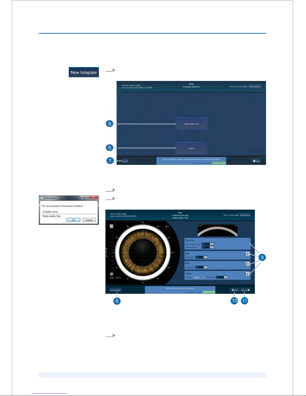
8.4.6.1
Creating treatments based on default values
1.
To create a new treatment which is based on determined parameter default
values, click the ‘New template’ button (Fig. 54/2).
Fig. 55: ‘Flap’ ‘Template selection’ screen (new template)
ð
The ‘Template selection’ screen opens (Fig. 55).
2.
Click the ‘Default’ button (Fig. 55/5).
3.
To save the new treatment template, enter a name in the entry field
(Fig. 56) and confirm with the ‘OK’ button.
Fig. 57: ‘Flap’ ‘Treatment planning’ screen (new template)
ð
The
‘Treatment planning’ screen (Fig. 57) based on the determined
parameter default values opens.
4.
View or modify the corresponding treatment data (Fig. 57/9).
Fig. 56: ‘Add template’ dialog box
SOFTWARE
8
SKU: 70005780TPV * Version 6 * UM-100010770 GB
8 - 30
Page 97
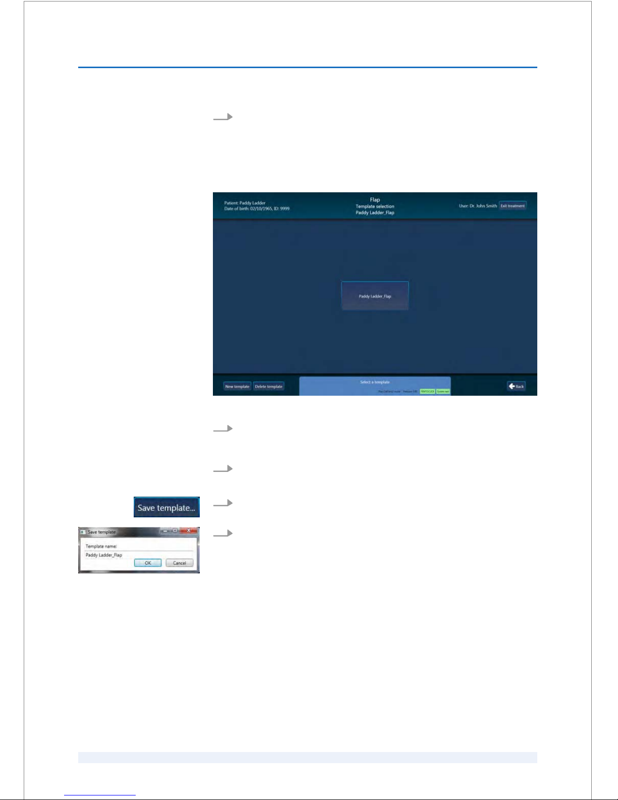
5.
To start the treatment, click the ‘Approve’ button (Fig. 57/11) to confirm the
parameter values.
To save the treatment, click the ‘Exit treatment’ button (Fig. 57).
8.4.6.2
Creating treatments based on a template
Fig. 58: Treatment template (example)
1.
Select the treatment template in the ‘Template selection’ screen (Fig. 58) to
create a new treatment which is based on determined parameter values for
a particular patient.
2.
In the ‘Treatment planning’ screen (Fig. 57) view or modify the corre‐
sponding treatment data.
3.
To save the changed treatment template, click the ‘Save template ...’
button.
4.
Enter a new template name and confirm with the ‘OK’ button.
ð
The treatment can now be executed.
Fig. 59: ‘Save template’ dialog box
(example)
SOFTWARE
8
SKU: 70005780TPV * Version 6 * UM-100010770 GB
8 - 31
Page 98
8.4.7
Editing treatments
Precondition:
– A patient must be selected as described in
Ä
Chapter 8.4.2 ‘Selecting patients’
on page 8 - 25.
1.
Select the treatment that you want to edit
Ä
Chapter 8.4.5 ‘Selecting treat‐
ments for execution’ on page 8 - 27.
2.
Verify the procedure parameter values in the relevant
‘Treatment summary’
screen (Fig. 52).
3.
If required, click the ‘Back’ button and modify the procedure parameter
values.
4.
To save any changes, click the ‘Exit treatment’ button and confirm with
‘Yes’ .
8.4.8
Deleting treatments
Deleting a treatment is only possible if the treatment has not been performed yet.
Precondition:
– A patient must be selected (see
Ä
Chapter 8.4.2 ‘Selecting patients’
on page 8 - 25).
1.
Select the treatment that you want to delete as described in
Ä
Chapter 8.4.5
‘Selecting treatments for execution’ on page 8 - 27.
2.
Click the ‘Delete’ button over the highlighted row (Fig. 51/3).
3.
To delete the treatment, confirm with ‘Yes’ in the warning message.
SOFTWARE
8
SKU: 70005780TPV * Version 6 * UM-100010770 GB
8 - 32
Page 99
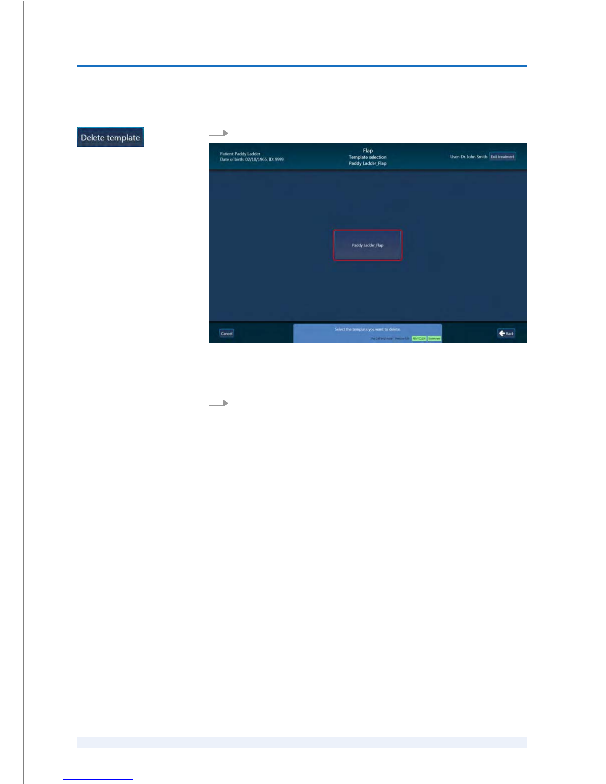
8.4.9
Deleting treatment templates
1.
To delete a treatment template, click the ‘Delete template’ button (Fig. 54).
Fig. 60: ‘Template selection’ screen
ð
All treatment templates are displayed with red highlighted frames
(Fig. 60).
2.
Click the treatment template you want to delete and confirm with ‘Yes.’
8.4.10
Treatment records
A treatment record contains the following information:
n GUI software version
n User (surgeon) name
n Patient data
n Intervention date
n Images from the OP camera before the intervention
n Images from the OCT B scan before the intervention
n Treatment status
n Parameter values
n Images from the OP Cam after the intervention
n Images from the OCT B Scan after the intervention
SOFTWARE
8
SKU: 70005780TPV * Version 6 * UM-100010770 GB
8 - 33
Page 100
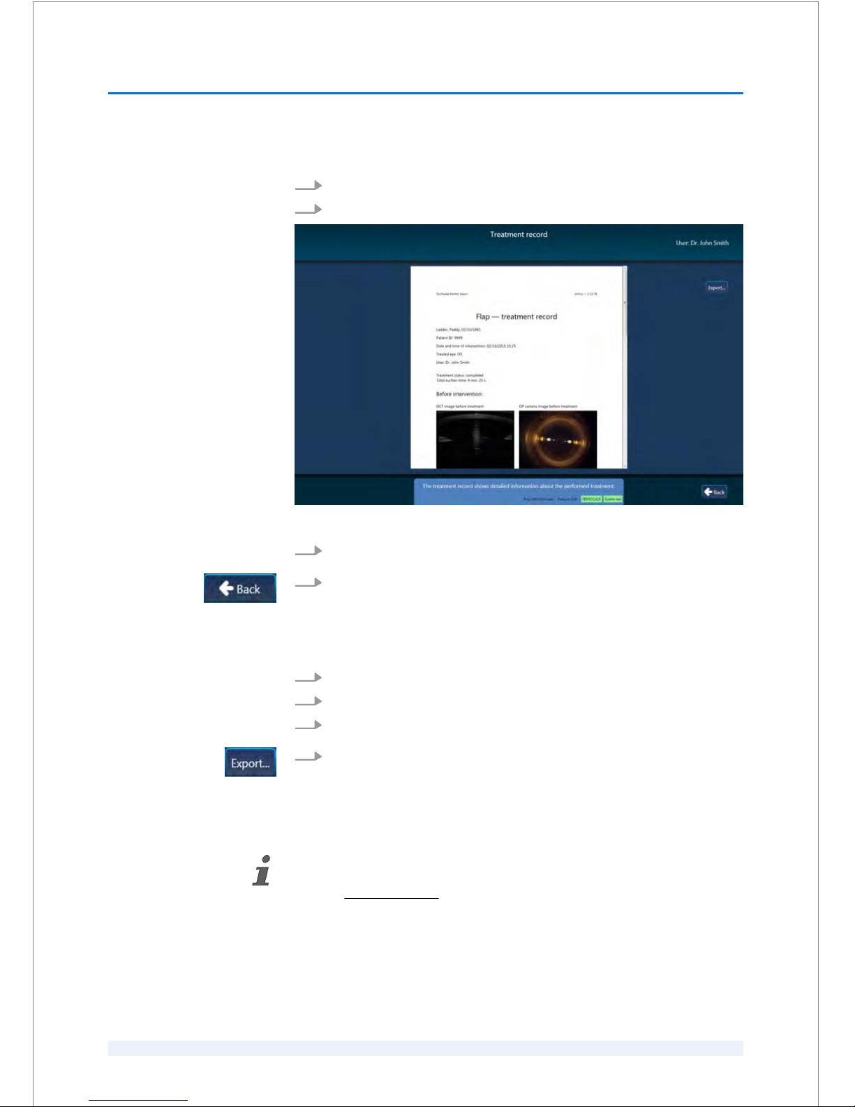
1.
Select the treatment record that you want to view (see Fig. 51).
2.
Click the ‘Treatment record’ button (Fig. 51/4) in the highlighted row.
Fig. 61: ‘Treatment record’ screen (example)
3.
The treatment record's data appear in the ‘Treatment record’ screen.
4.
To close the ‘Treatment record’ screen, click the ‘Back’ button.
1.
Select the treatment record that you want to export (see Fig. 51).
2.
Click the ‘Treatment record’ button (Fig. 51/4) in the highlighted row.
3.
Insert a USB memory stick in the ‘USB’ port at the start-up panel.
4.
Click the ‘Export...’ button in the ‘Treatment record’ screen.
ð
The treatment record's data is now saved on the USB memory stick.
8.5 Procedure parameters
For detailed information about the relevant procedure parameter values refer to the
addendum ‘VICTUS Femtosecond Laser Platform, SW V3.3 SP02 (English)’ (docu‐
ment no.
ADD-100011422)!
Viewing a treatment record
Exporting a treatment
record
SOFTWARE
8
SKU: 70005780TPV * Version 6 * UM-100010770 GB
8 - 34
 Loading...