

Page 1
DOCUMENT
VERSION
2.1
DRIVER ASSISTANT, TASK MANAGEMENT
AND NAVIGATION SYSTEM
USER MANUAL
Page 2

2
AutoGRAPH-NAVIGATOR • USER MANUAL
Table of content
Introduction ..........................................................................................................................4
Software Copyright Notice ...................................................................................................6
Product Overview ................................................................................................................6
Technical Specications ......................................................................................................7
Technical specications....................................................................................................7
Functional specications ..................................................................................................8
Scope of supply ...................................................................................................................9
Components of AutoGRAPH-NAVIGATOR .......................................................................10
Basic ..............................................................................................................................10
Control buttons ............................................................................................................... 11
Interface connectors ..........................................................................................................12
Getting started ...................................................................................................................13
SIM installation ...............................................................................................................13
MicroSD card installation ...............................................................................................14
External power connection .............................................................................................15
Device turning off ...........................................................................................................16
Interface language .........................................................................................................17
Alert signal .........................................................................................................................17
Main menu .........................................................................................................................18
Settings menu....................................................................................................................19
Preferences ....................................................................................................................19
Connection .....................................................................................................................22
Navigation..........................................................................................................................25
Map selection .................................................................................................................26
Status bar .........................................................................................................................28
Address searching .............................................................................................................31
Auto routing .......................................................................................................................32
Auto informer .....................................................................................................................34
Task management ............................................................................................................36
New task ........................................................................................................................36
Task control ....................................................................................................................37
Messaging .........................................................................................................................39
TechnoKom © 2015
Page 3

AutoGRAPH-NAVIGATOR • USER MANUAL
New message ................................................................................................................39
Inbox ..............................................................................................................................39
Outbox............................................................................................................................40
Voice communication.........................................................................................................41
Receive a call .................................................................................................................41
Make a call .....................................................................................................................41
Drivers installation .............................................................................................................43
Device settings ..................................................................................................................45
NAVIGATOR conguration tool .....................................................................................46
Registration on server .......................................................................................................51
3
TechnoKom © 2015
Page 4

4
AutoGRAPH-NAVIGATOR • USER MANUAL
Introduction
This User Manual applies to AutoGRAPH-NAVIGATOR devices of revision 2.0 (hereafter –
device) produced by TechnoKom Ltd. The User Manual contains installation and connection
procedures of this device, as well as its function and control. This Manual constitutes
the Operating Rules to be observed to ensure successful operation of the device and its
compliance to warranty provisions.
For proper operation of the AutoGRAPH-NAVIGATOR device, a user should be aware of
operating principles of the vehicle tracking system as a whole, as well as understand functions
of its individual components. Therefore, it is highly recommended to study the fundamentals
of operation of GPS navigation, GSM communication, peculiarities of short message service
(SMS), GPRS and the Internet before starting.
Some functions of AutoGRAPH-NAVIGATOR devices depend on capacities and conguration of the
IMPORTANT
existing mobile network operator (MNO). Furthermore, some functions may be disabled by the operator,
or their operating range may be limited due to the settings of the network. To check availability of a
certain function, contact your mobile network operator.
All information on functions, functional capabilities and other specications related to AutoGRAPH-
IMPORTANT
TechnoKom © 2015
NAVIGATOR devices, as well as all information contained in this User Manual is based on current data
(at time of writing) and is deemed to be valid as of the date of publication. Technokom reserves the
right to modify the information or specications without prior notice or commitment.
Page 5

AutoGRAPH-NAVIGATOR • USER MANUAL
5
Software Copyright Notice
Products of TechnoKom referred to in this Manual may incorporate software stored in
semiconductor memory or other media, copyrights to which belong to TechnoKom or third
parties. Laws of the Russian Federation and other countries secure certain exclusive rights
of TechnoKom and third parties to the software, which is subjected to copyright, for example,
exclusive rights for distribution or reproduction.
Therefore, any alteration, reverse engineering, distribution or reproduction of any software
incorporated in TechnoKom products, is prohibited to the extent provided by law.
Furthermore, purchase of TechnoKom products does not imply direct, indirect or other
granting of any licenses related to copyrights, patents and patent applications of TechnoKom
or any third party, except for an ordinary, nonexclusive free license for use, which is granted
in virtue of law upon each sale of the product.
Communication protocol between AutoGRAPH-NAVIGATOR devices and communication
data server is considered to be condential information and intellectual properly of TechnoKom.
The communication protocol between the AutoGRAPH-NAVIGATOR devices and a
communication data server shall be transferred by TechnoKom to integrators and software
manufacturers only upon signing the Condentiality Undertaking.
Unauthorized distribution of protocol being used for communication between AutoGRAPHNAVIGATOR devices and communication data server is strictly prohibited.
Product Overview
AutoGRAPH-NAVIGATOR is a driver assistant, task management and navigation system
which provides following features:
• vehicle tracking and navigation;
• control of movement parameters and vehicle operation;
• task management;
• auto routing and route control;
• messaging;
• voice communication;
• sending vehicle operating status to dispatcher.
TechnoKom © 2015
Page 6

6
AutoGRAPH-NAVIGATOR • USER MANUAL
Technical Specifications
Technical specications
Description Value
GNSS receiver uBlox MAX-M8Q
Supported GNSS GLONASS+GPS / GALILEO / Beidou
Channels 72
Time to rst start1, s 26
Position accuracy1, m 2.0
Processor ARM Cortex A8 Core AM3354, 1GHz
RAM, Mb 512
External memory
Display 7’’, 800 x 480
Display type TFT, touchscreen
OS
GSM modem Yes
Communication
SIM holders 2
Antenna (GPS / GLONASS, GSM) Internal
Connection to PC USB 2.0
Built-in accelerometer / motion sensor Yes
Audio interface (GSM) / Loudspeaker amplier Yes
Built-in microphone Yes
Operating voltage, V 10...60
Power consumption at 12 VDC, mА 700
Type of internal backup battery Li-Polymer
Battery capacity, mАh 1500-4500
Battery life, hours ~ 1
Built-in battery Charger Yes
Operating temperature3,°С -40...+85
3G UMTS2 / GSM (GPRS / SMS) 850 / 900 /
microSDHC
up to 32 Gb
Microsoft Windows
Embedded Compact 7.0
1800 / 1900 MHz
1
With nominal navigation signals level -130dBm.
2
Optional.
3
Does not apply to the device battery.
TechnoKom © 2015
Page 7

AutoGRAPH-NAVIGATOR • USER MANUAL
Description Value
Weight, g 500
Dimensions, mm 205 х 115 х 15
Average life time, years 7
7
Functional specications
Specication given below is applicable to AutoGRAPH-NAVIGATOR rmware of version
2.0.0.15.
• Message handling via data server.
• Loading les from server.
• Voice communication.
• Task management.
• Routing.
• Route tracking.
• Autoinformer mode, intended for an announcement of public transport stops and other
information in public transport.
• Vehicle operation indication.
• Vector, internet and raster map support.
• Voice reporting about battery discharge and other events.
• Searching for an address in address base.
•
TechnoKom © 2015
Page 8
8
AutoGRAPH-NAVIGATOR • USER MANUAL
Scope of supply
№ Description Qty
1 AutoGRAPH-NAVIGATOR device 1
2 Power supply cable 1
3 Power adapter-bracket 1
4 3A fuse with a holder 1
5 SD-card, 4 Gb 1
6 Windscreen mount holder 1
7 Warranty certicate 1
3
TechnoKom © 2015
1
2
4
GB
5
6
Page 9
AutoGRAPH-NAVIGATOR • USER MANUAL
Components of AutoGRAPH-NAVIGATOR
Basic
1. Control buttons.
2. MicroSD card hole.
3. Mini USB connector.
4. Label with serial number1.
5. Main SIM holder1.
6. Backup SIM holder1.
7. Removable panel.
8. Power contacts.
9. Power connector.
9
1
To access component, the removable panel must be removed.
TechnoKom © 2015
Page 10
10
Control buttons
AutoGRAPH-NAVIGATOR • USER MANUAL
1. Switch On/O button
Short press turns on / off the display backlight. Long press
(longer than 3 seconds) turns on/ off the device.
2. Zoom in button in Navigation menu.
3. Zoom out button in Navigation menu.
4. Back
Returns to previous menu.
5. Searching
Opens address searching menu in the Navigation menu.
6. Main menu
Goes to the main menu.
7. Alert button
Long press (longer than 3 seconds) sends alert message
to server.
NOTE
i
TechnoKom © 2015
To avoid an accidental pressing, it is required the delay between sequent presses a
button must be at least 3 seconds. Otherwise presses aren’t processed.
Page 11
AutoGRAPH-NAVIGATOR • USER MANUAL
11
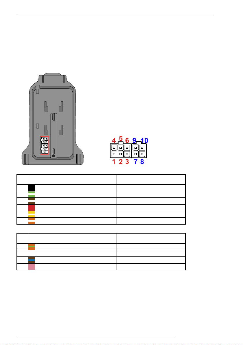
Interface connectors
Power connector
The device power connector is arranged on the power adapter-bracket, supplied with the
device.
№ Colour of a wire in a cable Assignment
1 Black -Vin
2 Green with a white strip CAN (H)*
3 Brown with a white stripe RS-485 (B)*
4 Red +Vin
5 Yellow with a white stripe CAN (L)*
6 Orange with a white stripe RS-485 (A)*
№ Colour of a wire in a cable Assignment
7
8 Reserved ---
9
10 Pink 1-Wire*
* Not available in the current version of AutoGRAPH-NAVIGATOR.
Orange with a green stripe RS-232 RxD*
Brown with a blue stripe RS-232 TxD*
TechnoKom © 2015
Page 12
12
AutoGRAPH-NAVIGATOR • USER MANUAL
Getting started
Before starting the operation, ensure that the AutoGRAPH-NAVIGATOR device is congured,
SIM and SD cards are installed.
All necessary information on the device conguration, SIM and memory card installation is
given below. It is highly recommended to study this information before starting the device
installation procedure.
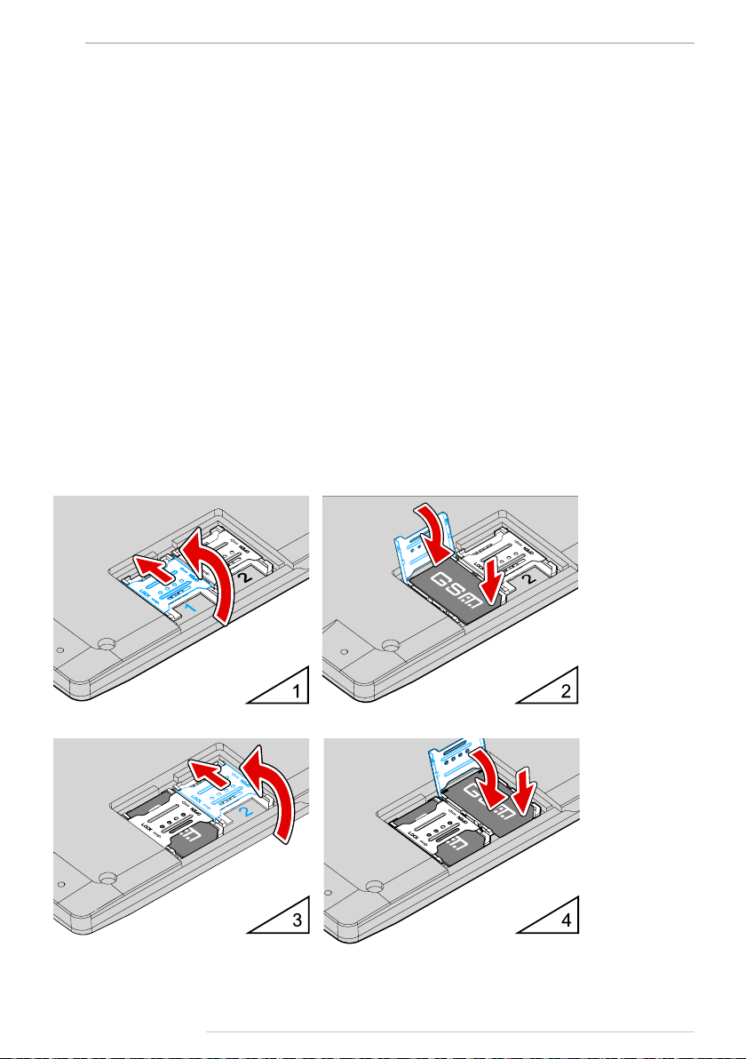
SIM installation
AutoGRAPH-NAVIGATOR is equipped with a holder for two SIM cards. For proper operation,
it is quite sufcient to insert the main SIM card into the device. But the backup card provides
the appropriate operation of the device even if the main SIM card is damaged.
To insert SIM cards:
• Ensure that the AutoGRAPH-NAVIGATOR device is turned off.
• Remove the removable panel of the device back cover.
• Insert a SIM card in the holder intended for the main SIM card (number 1). SIM holder are
marked with numbers on the PCB. To open the holder cover, shift it from the edge of the PCB
and open (Fig.1, i.1). Be sure that the SIM card is inserted into the retaining slot with its cut
angle facing the edge of the printed circuit board (Fig.1, i.2).
Fig.1. SIM cards installation.
TechnoKom © 2015
Page 13
AutoGRAPH-NAVIGATOR • USER MANUAL
• If necessary, insert a second SIM card in the holder intended for the backup SIM card
(Fig.1, i.3). Be sure that the SIM card is inserted into the retaining slot with its cut angle
facing the edge of the printed circuit board (Fig.1, i.4).
• When the SIM cards are connected, place the removable panel back.
Specify PIN code of all device SIM cards in the device settings before you turn on the device. Use the
IMPORTANT
IMPORTANT
conguration application «AGNavCong» to congure the device (for detailed information see section
«Device conguration» of this User Manual).
Do a test of a new SIM card in a cell phone before you install it into the device. This ensures that GPRS
/ SMS / USSD services are enabled and operate properly, the PIN code matches the code preset in the
device (in order to prevent locking), and a personal account associated with the SIM card has the
sucient balance for successful operation of the services.
13
NOTE
i
AutoGRAPH-NAVIGATOR starts operation with the main SIM card. If the main SIM card is unavailable
(disabled, damaged or not inserted), the device will switch to the backup SIM card.
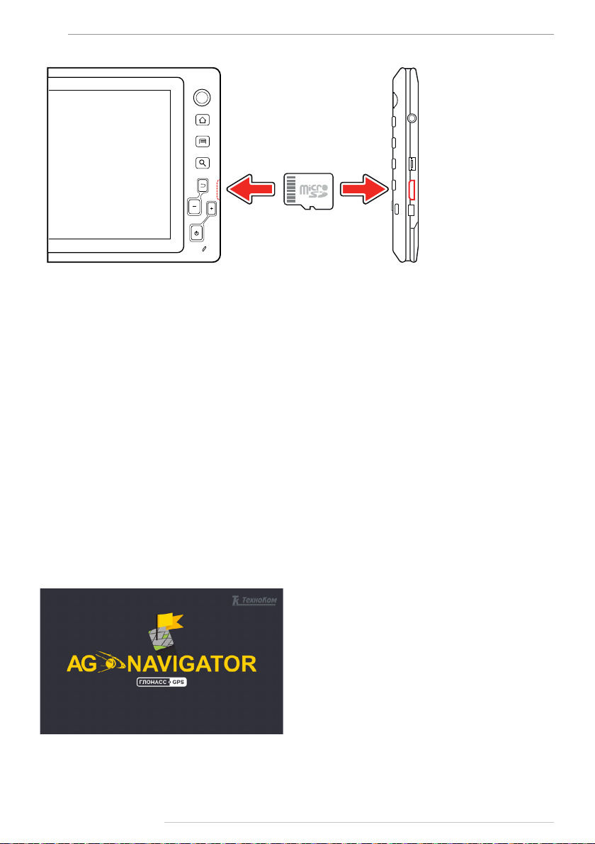
MicroSD card installation
AutoGRAPH-NAVIGATOR supports connection of a microSD card with capacity up to
32Gb. The device external memory is used to store rmware les, maps, task les and etc.
AutoGRAPH-NAVIGATOR is supplied with 4Gb microSD card.
BEFORE THE INSTALLATION
The SD-card, supplied with the device, contains all les required for the proper operation of
the AutoGRAPH-NAVIGATOR device.
Load all necessary maps in the device SD-card. All maps must be located in the folder
\AGMap of the SD-card.
SDCARD INSTALLATION
MicroSD card slot is located on the device right side panel.
To install SD card in the device:
• Ensure that the AutoGRAPH-NAVIGATOR device is turned off.
• Insert a microSD-card in the slot with the card’s contacts upward (Fig.2).
To remove the microSD card, gently push the card’s external edge and release it. Then
remove the card.
TechnoKom © 2015
Page 14
14
Fig.2. SD-card installation.
AutoGRAPH-NAVIGATOR • USER MANUAL
External power connection
The AutoGRAPH-NAVIGATOR device is connected to the power supply source through the
interface cable supplied with the device. Also the device is supplied with power adapterbracket intended to connect the device to power source using the interface cable. The power
adapter-bracket is also used to mount the device on the windscreen holder.
To connect external power to the device:
• Mount the power adapter-bracket on the back side of the device. Ensure that the contacts
on the inside of the power adapter-bracket match the power contacts on the device.
• Connect the interface cable supplied with the device, to the vehicle power source. When
making connections, pay special attention to the safety rules stipulated by the regulations
for motor vehicle repair procedures. All connections should be properly isolated and securely
connected.
• Connect the interface cable to the interface connector of the power adapter-bracket.
• The AutoGRAPH-NAVIGATOR device starts operation immediately after the power
connection. The device start-up window is given on Fig.3.
Fig.3. Start-up window.
TechnoKom © 2015
Page 15
AutoGRAPH-NAVIGATOR • USER MANUAL
To turn on the device when external power is disconnected:
• Press and hold Switch On/Off button located on the device front panel, for 3 seconds. The
device will start loading.
• When external power is disconnected, the device is powered by internal backup battery.
An approximate battery life time is 1 hour.
15
IMPORTANT
When the device system have been loaded, the device runs the work screen – Navigation
menu. This menu is intended to navigate and track an asset, and calculate route to the
selected destination.
To go to the main menu, press the Menu button on the lower right of work screen (Fig.8). Main
menu provides quick access to the device main options.
Before turning on the device, when it is powered by internal battery, ensure that the battery is charged.
Otherwise, the device doesn’t turn on.
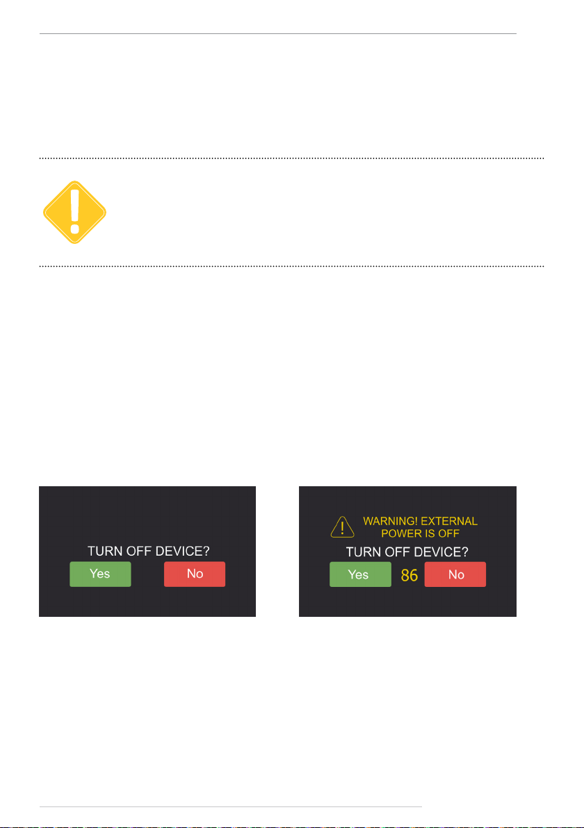
Device turning off
• To turn off the device using the Switch On/Off button, press and hold it for 3 seconds. The
device will prompt the user to conrm its turning off (Fig.4). Press Yes to turn off the device
or press No to cancel turning off and continue operation.
• The device can be turned off by virtual button. To do it, go to the Settings menu and press
the TURN OFF button (Fig.9).
Fig.4. Turn o conrmation.
To prevent over-discharging of the internal battery, automatic device turning off is provided
when the external power is disconnected. When the external power turns off, the device
noties the user about it using voice and text notications and prompts the user to turn off the
device (Fig.5).
Fig.5. Notication of external power turn o.
TechnoKom © 2015
Page 16
16
AutoGRAPH-NAVIGATOR • USER MANUAL
Interface language
It is recommended to select the necessary interface language when device turns on. To select
a language, select the Settings menu in the Main menu, then select Preferences/Common
and set up the necessary language (Fig.6).
Fig.6. Language selection.
When the language is selected, restart the device to apply changes. To turn off and turn on
the device, follow instructions given in previous sections.
Alert signal
In an emergency, you can send an alert signal – SMS message to data server. To do it, press
and hold for at least 3 seconds the Alert button on the device front panel.
Fig.7. Alert button.
TechnoKom © 2015
Page 17

AutoGRAPH-NAVIGATOR • USER MANUAL
17
Main menu
When the device has turned on, press the Menu button in the Navigation menu to go to the
Main menu.
Fig.8. Main menu.
Main menu provides quick access to the device other menus. Described below is the Main
menu options:
• Navigation – allows the vehicle navigation and tracking.
• Sensors – provides indication of the vehicle operation parameters. The menu is not
available in the current version of rmware.
• Maps – provides list of available maps.
• Modes – allows selection of the device operation mode.
• Tasks – provides list of driver tasks.
• Messages – provides messaging function: message transmission and reception.
• Voice call – provides voice calls.
• Settings – provides access to the device settings.
TechnoKom © 2015
Page 18

18
AutoGRAPH-NAVIGATOR • USER MANUAL
Settings menu
At rst start, it is recommended to set up the device. To do it, go to the Settings menu by
selecting the SETTINGS option in the Main menu.
Fig.9. Setting menu.
Described below is options available in the Settings menu:
• TURN OFF button – turns off the device.
• Connection – opens the Connection menu intended to indicate operation of GNSS and
GSM modules of the device.
• Preferences – opens the device settings menu.
• About system – provides information about the device.
To return to the Main menu, press the Menu button. To go to the previous menu, press the
Back button.
Detailed information on options available in each menu is given in sections below.
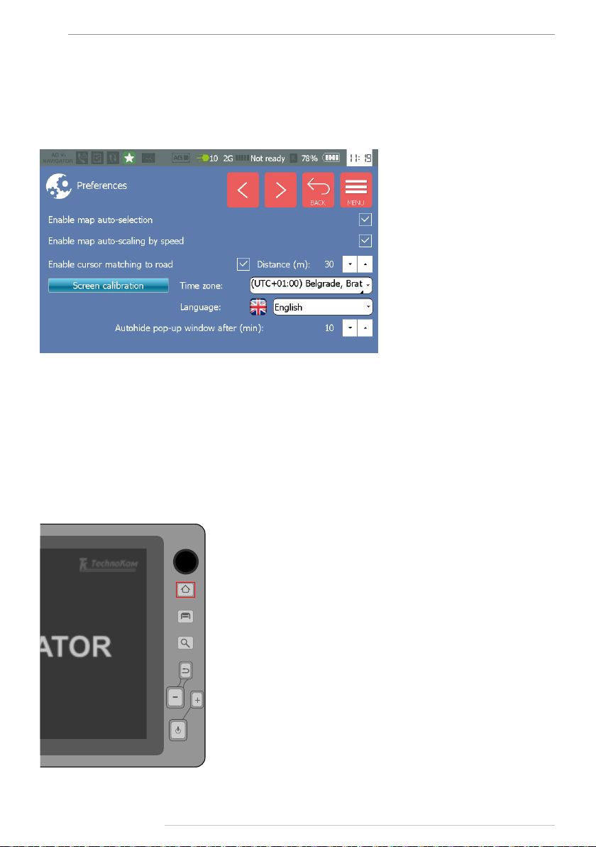
Preferences
Select the Preferences option in the Settings menu to go to access the device settings.
The Preferences menu consists of two sections: Common and Sound.
To set up the device general settings, such as time zone, language, maps auto selection and
etc., go to the Common menu. To set up the device sound settings, go to the Sound menu.
Fig.10. Preferences menu.
TechnoKom © 2015
Page 19

AutoGRAPH-NAVIGATOR • USER MANUAL
To go to the next page in the Common and Sound menus, use button . To go to the previous
page in the Common and Sound menus, use button .
Common settings
Fig.11. Common menu.
Settings available in the Common menu is described below:
• Enable map auto-selection – enables automatic selection of a map from the list of
available maps to display the vehicle position if the selected map does not cover vehicle
location area. List of available maps is given in the Maps menu. Also the Maps menu allows
the user to select other map to view vehicle position.
• Enable map auto-scaling by speed – enables automatic adjustment of map scale
relating to vehicle speed providing the smaller scale for the higher speed.
• Enable cursor matching to road – enable matching of vehicle cursor to road if vehicle is
not far from the road than the specied distance. The distance must be specied in meters.
This option allows vehicle position correction.
Sample tracks when the option are enabled and disabled is given on Fig.12:
19
1 – option is disabled. 2 – option is enabled.
Fig.12. Application of “Enable cursor matching to road” option.
• Screen calibration button – starts touchscreen calibration procedure. To calibrate the
device touchscreen, it is necessary to set and hold cursor in the center of the target on the
screen. Complete all calibration steps following the instruction at the top of display. The
touchscreen calibration is intended to adjust the sensor response to user touches. If incorrect
sensor response occurs, it is recommended to make touchscreen calibration.
• Time zone – select the necessary time zone in the drop-down menu.
• Language – select the necessary language of the device interface. The devices restart is
required to apply language settings.
• Auto hide pop-up window after (min) – specify an interval of auto hiding of pop-up windows.
TechnoKom © 2015
Page 20

20
Sound settings
Fig.13. Sound menu.
• Enable sounds – turns on sound notication of different events, e.g. geofence entrance.
• Sound type – select voice type of sounds in the drop-down menu.
• Enable system sounds – turns on sound notication of system events, e.g. external
power shutdown.
• Volume level (from 0 to 10) – set sounds volume using Up and Down buttons. Volume
level ranges from 0 to 10: minimum value is 0, maximum value is 10.
• Voice call volume (from 1 to 14) – set voice call volume using Up and Down buttons.
Voice call volume level ranges from 1 to 14: minimum value is 2, maximum value is 14.
• Microphone gain (from 1 to 8) – set device microphone gain using Up and Down buttons.
Minimum gain is 1, maximum value is 8.
AutoGRAPH-NAVIGATOR • USER MANUAL
TechnoKom © 2015
Page 21

AutoGRAPH-NAVIGATOR • USER MANUAL
21
Connection
Connection menu is intended to indicate operation of GLONASS/GPS receiver and GSM
modem of the AutoGRAPH-NAVIGATOR device.
The menu consists of two sections:
• GSM – provides indication of GSM modem operation.
• GPS – provides indication of GLONASS/GPS receiver operation.
Fig.14. Connection menu.
GSM menu
In this menu, the user can check GSM modem operation, including state of le loading, data
transmission, and etc.
Information available in this menu is described below:
1. Serial number – AutoGRAPH-NAVIGATOR serial number.
2. GSM signal level in dBm.
3. Active SIM – SIM number currently used by the device: 1 – main SIM, 2 – backup SIM.
4. Modem status – GSM modem current status. If GSM modem is ready, its IMEI is
displayed. Also data transmission state is indicated in this eld. The device collects
coordinate data and driver statuses, and sends them to data server. If there is no data to be
transferred, the messages “No data” is displayed. The modem last operation and time of the
operation are displayed in the next string, e.g “Modem was restarted: 1-10:03:37”, where
1 – time spent for the operation (in ms), 10:03:37 – time of operation.
5. File loading state – indicates state of loading the le from data server.
Fig.15. GSM modem status.
TechnoKom © 2015
Page 22

22
AutoGRAPH-NAVIGATOR • USER MANUAL
GPS menu
The GPS menu provides indication of GLONASS/GPS receiver operation.
The receiver mode is displayed in the Mode eld. The device receiver supports hybrid
navigation system, e.g. GLONASS+GPS.
When GNSS signal is pure, the warning about loss of accuracy is shown. Current position
accuracy is displayed on the right of the warning sign.
To enable additional menu providing detailed information on GNSS signal and satellites
location, press button (Fig.16).
This menu contains the receiver logs, GNSS signal digram and satellites position map
(Fig.17):
1. Receiver logs contain service information on the receiver operation.
2. Horizon visibility diagram displays location of GLONASS and GPS satellites
relative to the device, which the device is connected to. GPS satellites are denoted with
label , GLONASS satellites are denoted with label .
3. Number of visible GLONASS (GLS) and GPS satellites.
4. Signal to noise diagram for GPS satellites which the device is connected to. X-axis
contains number of GPS satellites providing the device location. Y-axis displays signal to
noise value (in dB) of a satellite.
5. Signal to noise diagram for GLONASS satellites. The diagram is generated similar to
the GPS satellites diagram.
Fig.16. GPS menu.
Fig.17. GLONASS/GPS state.
TechnoKom © 2015
Page 23

AutoGRAPH-NAVIGATOR • USER MANUAL
23
About system
To view information about system, select the About system option in the Settings menu (Fig.9).
In addition to information about the device system, this menu allows the user to update the
device rmware.
Fig.18. About system.
To update the device rmware:
1. Remove SD-card from AutoGRAPH-NAVIGATOR.
1. Connect the SD-card to a PC.
2. Create a new folder in the SD-card (in root directory).
3. Rename new folder by “newversion”.
4. Copy an update le in the \newversion folder. The update le has the next format –
AGNV-2.0.0.1.eraw, where 2.0.0.1 is a rmware version.
5. Insert the SD-card with the required update le into AutoGRAPH-NAVIGATOR, then
turn on the device.
6. When the device system has been loaded, go to the About system menu.
7. Press the Update button in this menu and wait for the updating nishing.
8. It is not available to install the updates which have been installed already. So, when
trying to load already installed update, the updating procedure won’t start.
TechnoKom © 2015
Page 24

24
AutoGRAPH-NAVIGATOR • USER MANUAL
Navigation
The AutoGRAPH-NAVIGATOR device provides real-time vehicle tracking and navigation. To
start vehicle navigation, go to the Navigation menu.
Fig.19. Navigation menu.
On the Navigation menu, the vehicle current position is displayed on a map using a vehicle
cursor (Fig.19). The cursor moves along the vehicle and displays direction of movement.
The vehicle current speed is indicated on the lower right of the screen. The street where the
vehicle is in, is displayed on the lower left of the screen.
To adjust map scale, use on-screen buttons and . Also there are Zoom in and Zoom out
buttons on the front panel of the device.
Quick buttons (Fig.19) provide easy access to the device other menus.
Goes the Inbox menu providing a list of incoming messages. A number of new incoming
messages are displayed on the Status bar.
Goes to the Task menu to view new tasks received by the device. When the device
receives a new task, the New task indicator on the Status bar turns on.
Goes to the Status menu allowing selection of a driver status. The driver current status
is displayed on the Status bar. Information on driver statuses is sent to the server along
with other data providing real-time driver status monitoring in the Dispatch software.
Goes to the Main menu.
TechnoKom © 2015
Page 25

AutoGRAPH-NAVIGATOR • USER MANUAL
25
Map selection
The user can select any map of supported formats for the Navigation menu. AutoGRAPHNAVIGATOR supports vector, raster and online maps.
Loading a new map in the device
All necessary maps should be stored in the \AGMap folder in the SD-card root directory.
• The device supports vector maps of .agv format. Vector maps of other formats are required
to be converted to .agv format before loading in the device.
• Prepared vector map should be stored in the \AGMap folder in the SD-card root directory.
• To load a raster map in the device, all les of the map – 1 le of .bmp format and 1 le of
.map format, must be stored in the \AGMap folder in the SD-card root directory.
• To load an internal map in the device, its cache les must be saved in the \AGMap folder
in the SD-card root directory.
Fig.20. AGMap folder.
NOTE
i
To convert a vector map to .agv format, use Vector map converter supplied with the AutoGRAPH.
NET Dispatch software. The AutoGRAPH.NET Dispatch software can be downloaded for free from
TechnoKom ocial web-site.
TechnoKom © 2015
Page 26

26
Map selection
To select the necessary map, go to the Maps menu (Fig.21). To do it, select the Maps option
in the Main menu.
Fig.21. Maps menu.
• All maps of the supported formats, loaded in the /AGMap folder on the device SD-card,
are available in the Maps menu.
• To open a map, click the map. The map loading will be started. A map loading time depends
on the map size.
• The current selected map is displayed at the top of list, e.g. chel_road.agv map on Fig.21.
• To view information about selected map and set up its level of detail, press the button .
• To scroll the list of maps, use Up and Down buttons on the left of the screen.
AutoGRAPH-NAVIGATOR • USER MANUAL
To go to the Navigation menu, press the Map button at the top.
To return to the Main menu, press the Menu button.
TechnoKom © 2015
Page 27

AutoGRAPH-NAVIGATOR • USER MANUAL
27
Status bar
Status bat at the top of the device screen provides indication of important events and the
device operation. The status bar is always on top. Description of status bar indicators is given
below.
Fig.22. Status bar.
MISSED CALL
The indicator noties the user about missed incoming call. To view details of the missed call,
go to the Voice call menu.
Missed call.
No missed calls.
NEW TASK RECEIVED
The indicator noties the user about receiving a new task. To view the received task, go to
the Task menu.
New tack is received.
No tasks.
DATA COMMUNICATION
The indicator indicates state of data communication: data loading from server or data
transmission to server.
Data communication is in progress.
No data is being sent or received.
DRIVER STATUS
The indicator displays the driver current status. The indicator changes depending on the
selected status. To set other status, go to the Status menu by pressing the Status button in
the Navigation menu.
Driver status is Ready.
TechnoKom © 2015
Page 28

28
INCOMING MESSAGE
The indicator noties the user about a new incoming message. A numbered badge on
the right of the indicator displays a number of new incoming messages. To read incoming
messages, go to the Messages menu. Quick access to the list of incoming messages is
provided by the Messages button on the Navigation menu.
12 incoming messages.
No message.
CONNECTION TO AutoGRAPH ON-BOARD CONTROLLER
The indicator indicates connection to the AutoGRAPH on-board controller. AutoGRAPHNAVIGATOR devices, equipped with RS-232 bus, support connection to the AutoGRAPH
controller to exchange data.
Connected to AutoGRAPH.
Do not connected to AutoGRAPH.
GNSS SIGNAL STATE
The indicator displays position acquisition state and a number of visible satellites.
AutoGRAPH-NAVIGATOR • USER MANUAL
Position is determined. Number of visible satellites – 10.
Position is not determined. Number of visible satellites – 0.
COMMUNICATION STANDARD
The indicator displays communication standard currently used: 2G, 3G, 4G, and etc.
The device is connected to 3G network.
The device is connected to 2G network.
GSM SIGNAL LEVEL AND MOBILE OPERATOR
The indicator indicates GSM signal level. A badge on the right of the indicator displays mobile
network operator.
Connected to GSM network provided by Rostelecom mobile operator.
GSM signal is not available.
TechnoKom © 2015
Page 29

AutoGRAPH-NAVIGATOR • USER MANUAL
ROAMING
The indicator notify the user about connection to roaming network.
Connected to roaming network.
Connected to home network.
INTERNAL BATTERY LEVEL
The indicator displays remaining battery level in % and as a diagram.
Battery is charged.
50% remaining.
Low battery level. It is recommended to connect the device to external
power.
Battery is discharged. It is highly recommended to connect the device to
external power to avoid the device switch off and battery over-discharging.
CURRENT TIME
24-hour format is used to display current time.
29
Current time – 12:00.
TechnoKom © 2015
Page 30

30
AutoGRAPH-NAVIGATOR • USER MANUAL
Address searching
To search for an address on the map, go to the Navigation menu and press the Searching
button on the device front panel.
Fig.23. Searching button.
Alternatively you can open this menu as follows:
• in the Navigation menu, click a map and hold until the Route menu appears;
• in the Route menu, press “Select address”.
In the Select address menu (Fig.24), rst you need to enter a city to search. The device
will show a list of items found in the installed address base. Next you need to select an
appropriate item in the list of available variants. In a similar way you need to select street and
house number for searching.
As an address is selected you can
nd it on map pressing the button
“ON MAP” on the upper right of the
main screen.
To calculate a route to the selected
address, press the “ROUTE” button.
Fig.24. Select address menu.
Address base installation
AutoGRAPH-NAVIGATOR uses default address base, loaded in the device SD card. If
you need to use other address base, you may copy the necessary address base le in the
\AddressBase directory on the device SD card. Only one address base le can be stored
in this directory. All address base les which are not used must be removed from the
\AddressBase directory
AutoGRAPH-NAVIGATOR supports address base of the .aga2 format. This is a format used
in the AutoGRAPH 5 Dispatch Software.
TechnoKom © 2015
Page 31

AutoGRAPH-NAVIGATOR • USER MANUAL
31
Auto routing
AutoGRAPH-NAVIGATOR provides calculation of optimal route to the selected destination.
Fig.25. Following a route.
Also the device provides route tracking:
• when a vehicle follows a route, its current position and movement direction are indicated
on screen;
• when a vehicle departures the route, the device noties of it using voice notication;
• when a vehicle achieves the destination, the device noties of it using voice notication.
Before routing, ensure that the map used for routing is equipped with graph.
IMPORTANT
To check a map:
• Load the map in AutoGRAPH-NAVIGATOR.
• Turn on the device and go to the Maps menu by selecting Maps option in the Main menu.
• Select this map in the maps list to open it.
• Open information about selected map by pressing button in the Maps menu, and
ensure that the loaded map is equipped with graph.
Routing is available only on maps equipped with special graph.
TechnoKom © 2015
Page 32

32
To calculate route:
• turn on AutoGRAPH-NAVIGATOR and wait until the device acquires position. State of
positioning is indicated on the Status bar;
• open the required map with graph which will be used for route calculation;
• go to the Navigation menu of the device. To do it, select the Navigation option in the Main
menu;
• select a destination point on the map – tap the required point and hold until the routing
menu runs (Fig.26);
• set the selected point as terminal point of the route. To do it, press the Terminal point
option in the routing menu;
• the device will start calculation of optimal route from the
device current position to the selected point. The route terminal
point is designated with an icon (see Fig.25);
• when the route is calculated, AutoGRAPH-NAVIGATOR
starts the route tracking;
• when vehicle achieves the destination point, the device
nishes tracking;
• to nish the tracking manually and delete current route, open
the routing menu and select the Delete route option. The device
will nish the route tracking;
• to close the routing menu, press Cancel.
AutoGRAPH-NAVIGATOR • USER MANUAL
Fig.26. Routing menu.
• Alternatively you can select a terminal point by a certain address. AutoGRAPH-NAVIGATOR
supports searching for an address in internal address base. To select terminal point in the
address base, press Select address in the Route menu (Fig.26). It will open the Select
address menu intended to nd required address in address base. Detailed information on
how to search for the required address and calculate route to it is given in the “Address
searching” section of this User manual.
To be able to calculate a route till an address, the address base of .aga2 format is required.
IMPORTANT
Detailed information on address base installation see in the “Address searching” section
of this User manual.
TechnoKom © 2015
Page 33

AutoGRAPH-NAVIGATOR • USER MANUAL
33
Auto informer
The Auto informer mode is intended to customize AutoGRAPH-NAVIGATOR for the operation
in public transport. This mode provides automatic announcement of public stops and
advertisements.
Route preparation for the Auto informer mode
Route le is created in the Route Editor intended to prepare routes for AutoGRAPHNAVIGATOR and AutoGRAPH-INFO devices. This application compiles the le, including
sound les, stops list, and other les required to the proper route processing.
Route loading in AutoGRAPH-NAVIGATOR
Compiled route le must be loaded in \RouteControl folder located in the device SD-card root
directory. If there is no \RouteControl folder in the SD-card root directory, create it manually.
NOTE
i
To switch the device to Auto informer mode
• Turn on AutoGRAPH-NAVIGATOR and wait until the device acquires position. The state of
position acquisition is indicated on the Status bar.
• Then select the Modes option in the Main menu to go to the Modes menu (Fig.27). This
menu allows the user to switch the device to the required mode of operation. Current version
of the device rmware supports one mode – Auto informer.
• Switch the device to the Auto informer mode. This mode requires prepared route le. In this
mode, the device displays name of current route and vehicle next stop (Fig.28). If the route
le hasn’t been selected, the rout and next stop elds are empty.
• To select a route, press the Route button, then select the required route. The route list
(Fig.29) contains all route les stored in the \RouteControl folder. To scroll the list use Up and
Down buttons.
For more detailed information on route compilation, see the document “Route Editor”.
Fig.27. Modes.
Fig.28. Auto informer mode.
TechnoKom © 2015
Page 34

34
• When route is selected, the device starts operation in the Auto informer mode – announces
next stop name and noties of closing the vehicle doors .
Fig.29. List of available routes.
• When following the route, the device announces name of public transport stops which
vehicle enters. The next stop name is displayed on the device display (Fig.28). The Direct
route and Return route options provides selection of the route direction. Stops of both
directions can be congured in the Route Editor.
To return to the Navigation menu keeping Auto informer mode, press the Map button in the
Auto informer menu. To return back from the Navigation menu, press the Back button (Fig.30).
AutoGRAPH-NAVIGATOR • USER MANUAL
Fig.30. Return back to the
Auto informer menu.
TechnoKom © 2015
Page 35

AutoGRAPH-NAVIGATOR • USER MANUAL
35
Task management
AutoGRAPH-NAVIGATOR supports task management function providing control of tasks
performance by a driver.
Task le is a list of geofences which a vehicle must enter to. Depending on settings, task can be exact
NOTE
i
New task
Task les are created in the Task editor supplied with the AutoGRAPH.NET software. The
compiled task le can be sent to AutoGRAPH-NAVIGATOR via server or manually loaded in
the device SD-card. The transmission via server is provided by Chat module supplied with the
AutoGRAPH.NET software.
To create task le:
• Run the AutoGRAPH.NET software and install the Task editor if it hasn’t been installed yet.
• Install the Chat module if it is necessary to send task le to AutoGRAPH-NAVIGATOR via
server.
• Task le is compiled on the basis of geofences list. Add all required geofences into the
Task editor, then set geofences order and specify task options.
• Save the task le. To sent the le to the device via server, select Save and sent option in
the Task editor. To save the le in the device SD-card, select Save as option.
• The Task Editor creates following les: .kml, .agth. и agtz. The .kml, .agth. les are required
to copy load task in the device SD-card. All task les must be stored in the «Tasks» folder
located in the SD-card root directory. Sample structure of «Tasks» folder is given on Fig.31.
• The .agth le is required to send the task to the device via server. This le must be sent to
the device using Chat module.
• Also sound les can be associated with task le to play them when vehicle enters task
points.
• Sound les can be matched to task le using the Editor of public transport stops supplied
with the AutoGRAPH.NET software. Also all necessary sound les must be copied in the
\Tasks\Wav directory in the device SD-card.
requiring the exact order of geofences passing and not exact allowing random order of geofences
passing. The task is considered to be completed, if all geofences of task are passed.
IMPORTANT
To ensure le transmission via server servicing the AutoGRAPH-NAVIGATOR device, the device must
be added in the AutoGRAPH.NET software, as well as the user sending the le must have access to the
device data.
TechnoKom © 2015
Page 36

36
Fig.31. Sample Tasks folder.
Detailed information on how to create a new task using Task Editor and how to load task le in
NOTE
i
AutoGRAPH-NAVIGATOR is given in the “Application Note: AutoGRAPH-NAVIGATOR tasks and
messages” document.
AutoGRAPH-NAVIGATOR • USER MANUAL
Task control
• When task le is loaded in SD-card, insert the SD-card in the device. Then, turn on
AutoGRAPH-NAVIGATOR.
• If task le is sent via server, it will be loaded in the device as the device connects to GSM
network. Task les transmitted via server are also loaded in the \Task folder. When the
device receives a new task, the new task indicator on the Status bar turns on.
• To select a task and start its control, go to the Task menu. This menu contains a list of
tasks, stored in the \Task folder of the device SD-card. To scroll the list, use Up and Down
buttons.
• Move an interesting task to the preview menu to view task details (Fig.32): task start and
end date and short description.
• Then press the button to start the task control. When task is controlled, its status is
indicated on progress bar (Fig.32). If there is no task to be controlled, message “No task is
set, 0%” is displayed instead of the progress bar.
• The task performance state depends on the task settings. Exact task is considered
completed if its geofences have been passed in the specied order. Non-exact task is
considered completed if all task geofence have been passed ignoring the order.
• AutoGRAPH-NAVIGATOR supports processing of a task le with built-in route. The route
le of .agth or .agtz format can be created in the AutoGRAPH.NET software. Tasks with
specied routes allow route display on map providing optimal path of task points passing.
TechnoKom © 2015
Page 37

AutoGRAPH-NAVIGATOR • USER MANUAL
• If the device was turned off while task control, that task is automatically set to control after
the device turning on provided that the task progress is set to zero.
Fig.32. Task menu.
• To nish the task control, press the button (displayed instead of button , when a task
is set for control).
• When the task is set to control, the user can view a list of task geofences. To view the task
content, press the View button . Completed task points are highlighted green. Time before
a point displays the time remaining till the scheduled entrance to the point. Time after a point
displays the time remaining till the scheduled exit the point.
• Scheduled entrance and exit times can be set up when compiling task le in the Task
editor. A timeline is highlighted red if late arriving (or exit) is expected. If a vehicle arrives
late in a point, message “late” is displayed. If a vehicle stays on a point, message “delay”
is displayed. Also in case of late arriving and departure, AutoGRAPH-NAVIGATOR sends a
notication to a dispatcher.
37
Fig.33. List of task points.
• When a task is set to control, its points are displayed on map. Scheduled points are marked
with an additional label changing colour depending on the time remaining till the scheduled
entrance and exit (Fig.34).
• If both entrance and exit times are scheduled, at rst the device process the entrance time.
As vehicle arrives the point, the device starts processing of the point exit time.
Fig.34. Task points on map.
TechnoKom © 2015
Page 38

38
AutoGRAPH-NAVIGATOR • USER MANUAL
Messaging
AutoGRAPH-NAVIGATOR allows the user to send messages to dispatcher and
receive incoming messages. Messaging is provided by Chat module supplied with the
AutoGRAPH.NET dispatch software.
Fig.35. Messages menu.
To create new messages and receive incoming messages, turn on the device and go to the
Messages menu.
New message
To create a new message, go to the New menu providing a simple text editor (Fig.34).
Fig.36. New message. Fig.37. Templates.
To send new message, enter the required text then press Send button.
Messages which are sent from the AutoGRAPH-NAVIGATOR will be delivered to all
dispatchers provided with access to the device data. Also the user can use templates to
send quick messages. To send a template, go to the list of templates (Fig.37) by pressing the
Templates button on upper right of the New message window. Then tab a templates to send it.
Inbox
When device receives a new message, the new message indicator on the Status bar turns on.
A numbered icon on the right of the indicator displays a number of new incoming messages.
To view incoming message, go to the Inbox menu. New incoming messages are displayed on
the New tab. Incoming messages that have been read already are displayed on the Inbox tab.
TechnoKom © 2015
Page 39

AutoGRAPH-NAVIGATOR • USER MANUAL
Fig.38. Inbox. New messages. Fig.39. Inbox. Incoming messages.
To send a message to AutoGRAPH-NAVIGATOR use Chat module supplied with AutoGRAPH.
NET software.
• To view new incoming message, go to the Inbox menu on the New tab. Double click a
message opens it.
• When a message has been read, it is removed to the Inbox tab.
• To send a reply on an incoming message, press the button on the preview eld of the
required message.
• To delete a message, press the button on the preview eld of the required message.
The Inbox menu providing list of incoming
messages can be launched from the
Navigator menu by pressing the Messages
button (Fig.40).
39
Fig.40. Quick buttons of the Navigation menu.
Outbox
To view messages which have been sent by the device, go to the Outbox menu. If a message
is sent but not delivered yet, it is displayed on the Outbox tab. As the message is delivered to
the server, it is removed to the Sent tab.
Fig.41. Not delivered messages. Fig.42. Delivered messages.
• To delete an outgoing message, press the button on the preview eld of the required
message.
TechnoKom © 2015
Page 40

40
AutoGRAPH-NAVIGATOR • USER MANUAL
Voice communication
AutoGRAPH-NAVIGATOR allows the user to make and receive voice calls.
The device is equipped with an internal microphone and an internal loud speaker amplier to
provide voice call function.
Receive a call
• To make a call to the AutoGRAPH-NAVIGATOR device, dial a number of the device active
SIM.
• An incoming call is indicated on the screen (Fig.43).
• To answer a call, press the button .
• To decline a call, press the button . This button also allows to nish a call.
• During a telephone call, its duration is displayed on the device screen.
Fig.43. Voice call indication.
Make a call
To make a call on AutoGRAPH-NAVIGATOR, go to the Voice call menu (Fig.44). To do it,
select the Voice call option on the Main menu.
Upon the device turns on, some time is required to initialize GSM modem and become ready
to make voice calls. While GSM modem is not initialized, voice communication is not available
and keypad is disabled – label is displayed on top of menu (see Fig.44).
To make a voice call:
• Enter a number using keyboard. When entering, the number is displayed in the dial string,
e.g. 89510000000, on Fig.44. Alternatively, you can select a number from the phone book.
To do it, press the Contact button on the Voice call menu, then select a subscriber. Phone
number of the selected subscriber will be entered in dial string.
• To delete incorrect number from the dial string, press button
• To dial entered number, press button .
• When dialling, a call state is indicated above the dial string.
• AutoGRAPH-NAVIGATOR is equipped with a loud speaker amplier. The voice
communication is provided in a loudspeaker mode.
• To end the call, press button .
TechnoKom © 2015
Page 41

AutoGRAPH-NAVIGATOR • USER MANUAL
Fig.44. Voice calls menu.
41
NOTE
i
The keypad can be disabled using the NAVIGATOR conguration tool. In this case the label
is displayed on top of menu (see Fig.44), as well as the GSM modem is not initialized yet.
Last calls history is displayed on the Voice call menu. Only contact from the Phone book is
displayed in the short history. Depending on a call type, records are highlighted as follows:
• green – incoming call;
• red – missed call;
• blue – outgoing call.
To see full history of voice calls, press the History button. The History menu (Fig.45) contains
three sections:
• Missed – a list of missed calls;
• In – a list of incoming calls;
• Out – a list of outgoing calls.
To go to the Main menu, press Menu button in the Voice call menu. To return to previous
menu, press Back button.
Phone book of the Voice call menu is edited in the NAVIGATOR conguration tool. For more
detailed information see section “Device conguration”.
Fig.45. History of voice calls.
TechnoKom © 2015
Page 42

42
AutoGRAPH-NAVIGATOR • USER MANUAL
Drivers installation
This section covers the installation procedure of the AutoGRAPH-NAVIGATOR device drivers.
The AutoGRAPH-NAVIGATOR drivers (AGUSBDriver) can be downloaded for free from the ocial web
NOTE
i
To install the device drivers onto a Microsoft Windows 7 OS:
1. Download the archived drivers folder from the ofcial website of TechnoKom -
AGUSBDriver.zip le and extract les to a temporary directory on a hard drive.
2. Connect AutoGRAPH-NAVIGATOR to a PC using USB AM – USB miniB 5pin data
cable. The system will automatically search for new equipment – AG_Navigator (Fig.46).
site of the manufacturer (www.tk-nav.com). The drivers are compatible with Microsoft Windows XP, 7,
Vista, 8, Server 2003, Server 2008 and Server 2012.
Fig.46. New equipment «AG_Navigator».
3. Launch the driver update wizard for new equipment (AG_Navigator) and select “Browse
my computer for driver software” to search for drivers manually.
4. Browse to the location where the drivers are saved ant install the drivers (Fig.47).
TechnoKom © 2015
Page 43

AutoGRAPH-NAVIGATOR • USER MANUAL
Fig.47. Path to the drivers folder. Fig.48. The installation nishing.
5. When the driver is installed the system will automatically identify connected device
43
Fig.49. AutoGRAPH-NAVIGATOR device is identied.
TechnoKom © 2015
Page 44

44
AutoGRAPH-NAVIGATOR • USER MANUAL
Device settings
To congure the AutoGRAPH-NAVIGATOR, you need the NAVIGATOR conguration tool
(AgNavCong. exe). It is recommended to congure the device correctly prior the rst start.
NOTE
i
To congure the AutoGRAPH-NAVIGATOR follow the next:
• Before connecting the device to a PC, install the device drivers, if they have not been
installed yet. Instruction on how to install the drivers are given in the section “Drivers
installation”.
• Turn on AutoGRAPH-NAVIGATOR.
• Connect AutoGRAPH-NAVIGATOR to PC using mini USB Data-cable.
• Run the NAVIGATOR conguration tool (AgNavCong.exe).
• As the device settings have been read, it serial number and rmware version is displayed
on the NAVIGATOR conguration tool.
NOTE
i
• The device settings are grouped into four tabs:
GSM modem tab – is intended to congure GSM and GPRS settings;
Voice calls – is intended to congure voice communication and edit phone book;
Logging tab – is intended to enable logging options;
Log les tab – is intended to read log les from the device;
Settings protection tab – is intended to set a password to protect the device settings from
modication.
• Specify the necessary settings on each tab, then press the “Save” button to write new
settings in the device.
• Restart the device to apply new conguration.
• Now AutoGRAPH-NAVIGATOR is ready for operation.
Following sections contain description of settings on each tabs of the NAVIGATOR
conguration tool.
The last version of the NAVIGATOR conguration tool is available for free on the TechnoKom ocial
forum.
If AutoGRAPH-NAVIGATOR is processing a RAM intensive task (e.g. loading large size map), an error can
occur when connecting the device to PC. In this case it is recommended to load a map of low size (e.g.
an internet map instead of a vector one) and try to make the connection again.
If the device settings are protected from modication, the conguration tool will display an error
NOTE
i
TechnoKom © 2015
message when trying to write new settings. In this case you need to enter the protection password on
the Settings protection tab before applying new settings.
Page 45

AutoGRAPH-NAVIGATOR • USER MANUAL
45
NAVIGATOR conguration tool
GSM modem settings
To congure the device GSM modem operation, go to the “GSM modem” tab (Fig.50) of the
conguration tool and specify required settings according the description given below.
Fig.50. Tab «GSM modem».
Server section:
• Server – an IP address or domain name of the serve which AutoGRAPH-NAVIGATOR
transfers data to. The server IP address must be real and static.
• Port – a server port. This port number must be similar to a port specied in the server
settings.
SIM1 section
• APN – an access point name for the rst SIM card.
• User – a user name of the access point, specied in the “APN” eld.
• Password – a user password of the access point, specied in the “APN” eld
• PIN – a SIM1 PIN of the device. If the PIN check is disabled for the SIM card, leave the
eld empty or enter any four digits.
ВНИМАНИЕ
NOTE
i
Be careful specifying PIN. If wrong PIN is specied, it will block your SIM card!
GPRS settings should be taken from mobile operator, whose SIM- card is installed in the device. Typically
these settings can be seen on the operator’s website.
TechnoKom © 2015
Page 46

46
GSM modem section
• Enable modem turning on – is intended for development purpose and enables the
GSM modem turning on while the device operation. By default this option is enabled. If this
option is disabled, AutoGRAPH-NAVIGATOR functionality related to GSM modem will be
unavailable (data transmission and reception, message handling, and voice communication)
and the device will operate in ofine mode only recording data in internal memory.
• Enable modem usage – enables data reception and transmission using an internal GSM
modem. If this option is disabled, the AutoGRAPH-NAVIGATOR won’t transfer or receive
data, but it will be able to make voice calls.
AutoGRAPH-NAVIGATOR • USER MANUAL
IMPORTANT
NOTE
i
Voice communication settings
To congure voice communication go to the “Voice calls” tab (Fig.51).
For the device proper operation both options –“Enable modem turning on” and “Enable modem
usage” must be enabled.
The current rmware of the device does not support processing of the back-up SIM connection.
Fig.51. Voice calls tab.
• In order to allow outgoing voice calls from the device check the box “Enable outgoing
calls”. If this option is disabled the device is able to receive incoming calls only and the Voice
call menu of AutoGRAPH-NAVIGATOR is disabled.
• In order to enable manual phone number entering on the device, check the box “Enable
keypad”. If this option is disabled, It will be available to dial only phone numbers saved in the
device phone book.
TechnoKom © 2015
Page 47

AutoGRAPH-NAVIGATOR • USER MANUAL
Phone book
The phone book of AutoGRAPH-NAVIGATOR is intended to store phone numbers in the
device memory.
To add a number to the book, enter a subscriber name in the “Name” eld. Then enter the
subscriber’s phone number, including a prex for national call (+7) and save settings in the
device.
Fig.52. Phone book.
47
Logging settings
AutoGRAPH-NAVIGATOR records system events and operation information in log les which
can be used for device troubleshooting and diagnostics when it is necessary.
To set up logging, go to the “Logging” tab (Fig.53).
Fig.53. “Logging” tab.
Following options are available on the “Logging” tab:
• Enable message logging – allows the device to log events of message handling –
incoming and outgoing messages.
• Enable logging of the internal GPS receiver – allows the device to log GPS receiver
operation events.
• Enable logging of the GSM modem – allows the device to log GSM modem events.
• Enable voice call logging – allows the device to log events of voice communication.
Log les can be read from AutoGRAPH-NAVIGATOR using the NAVIGATOR conguration
tool. This capability is available on the “Log les” tab.
TechnoKom © 2015
Page 48

48
AutoGRAPH-NAVIGATOR • USER MANUAL
Log les content
To read log les from AutoGRAPH-NAVIGATOR, go to the “Log les” tab. There are ve
sections on this tab intended to display different types of log les.
Fig.54. “Log les” tab.
• General tab – is intended to read common logs.
• Messages tab – is intended to read logs of message handling.
• Voice calls tab – is intended to read logs of voice communication.
• GPS tab – is intended to read logs of GPS receiver.
• GSM tab – is intended to read log of GSM modem.
To read a log le:
• go to the tab of the required log and press the Update button;
• the list of available log les will be displayed on the tab;
• to load an available log le from the device to local folder, double click the le. The selected
le will be saved in the folder where the AGNavCong.exe le is located.
Log les of AutoGRAPH-NAVIGATOR are text les which can be opened using any test
editor. The device create a new log le every day. It means that each le contains daily logs
of the device. A log le name contains date of the le creation.
If no log le is found in the device or an error occurred when trying to request a list of log les,
ВНИМАНИЕ
the message “Failed to receive the list of log les” will be displayed on the status window of the
conguration tool.
TechnoKom © 2015
Page 49

AutoGRAPH-NAVIGATOR • USER MANUAL
49
Settings protection
Using the NAVIGATOR conguration tool, you can set a password to protect AutoGRAPHNAVIGATOR settings from modication. If the device settings are protect with password,
further settings modication will be available only after the protection reset.
To enable protection or to disable it, go to
the Settings protection tab (Fig.55).
When you open this tab, the protection
level of the connected device is displayed
(Fig.55, i.1).
Fig.55. Settings protection tab.
To enable settings protection:
• connect AutoGRAPH-NAVIGATOR to a PC;
• run the NAVIGATOR conguration tool and go to the Settings protection tab;
• in the drop-down list on the tab (Fig.55, i.1), select a level of protection:
Server – protects server settings: IP address/domain name and port;
Full – protects all settings of the device from modication.
• in the eld under the protection level selection menu, specify a password to protect
settings. Password can contain gures from 0-9, uppercase and lowercase letters of Latin
alphabet. The password length is not limited;
• press the Set button. If correct protection parameters are specied, the protection of the
selected level will be enabled in the device. Otherwise, an error message will be display on
the status window.
To disable settings protection:
• connect AutoGRAPH-NAVIGATOR to a PC;
• run the NAVIGATOR conguration tool and go to the Settings protection tab;
• in the eld under the protection level selection menu, enter the password which has been
set in the device;
• press the Clear button. If correct password is specied, the protection will be disabled.
To change the device password, rst you need to disable the protection, then set it again with
a new password.
TechnoKom © 2015
Page 50

50
Copyright © Chelyabinsk, 2015
All Rights Reserved.
www.tk-nav.com
info@tk-nav.com
TechnoKom ltd.
VEHICLE AND PERSONAL TRACKING SYSTEM
AutoGRAPH
GPSGLONASS
AutoGRAPH-NAVIGATOR • USER MANUAL
Registration on server
AutoGRAPH-NAVIGATOR sends data to the AutoGRAPH server of version 5.0.
The device can be set up to send data both to TechnoKom server or the third party AutoGRAPH
server.
The AutoGRAPH server 5.0 requires a user authorization to be able to provide access to data
of the devices serviced by the server.
If your AutoGRAPH-NAVIGATOR send data to the AutoGRAPH server of TechnoKom, send
user details to TechnoKom by email to register on server.
User information required for registration.
1. User login and password which will be used to access the server.
2. List of AutoGRAPH-NAVIGATOR device (including serial numbers) which an access
must be provided to.
3. To register more than one user, send separate list of devices for each user.
New user will registered on the server on the basis of specied information. Also an access to
the specied devices will be provided for the user.
To view data of AutoGRAPH-NAVIGATOR devices, use the AutoGRAPH 5 PRO dispatch
software. To load data from the AutoGRAPH server servicing AutoGRAPH-NAVIGATOR
devices, specify following server details in the AutoGRAPH 5 PRO: domain name – navigator.
tk-chel.ru, port 2230.
NOTE
i
The request on a user registration should be sent to mail@tk-chel.ru with title «Navigator».
TechnoKom © 2015
Page 51

TechnoKom ltd.
GPSGLONASS
AutoGRAPH
VEHICLE AND PERSONAL TRACKING SYSTEM
Copyright © Chelyabinsk, 2015
All Rights Reserved.
www.tk-nav.com
info@tk-nav.com
 Loading...