

Page 1
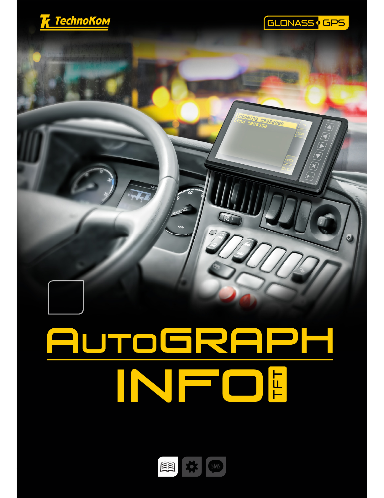
AutoGRAPH-INFO-TFT • USER MANUAL
1
TechnoKom © 2016
USER MANUAL
DOCUMENT
VERSION
1.0.0
Page 2

AutoGRAPH-INFO-TFT • USER MANUAL
2
TechnoKom © 2016
Page 3

AutoGRAPH-INFO-TFT • USER MANUAL
3
TechnoKom © 2016
Table of content
Software Copyright Notice ............................................................................................................................... 5
Introduction ............................................................................................................................................................5
Product Overview ................................................................................................................................................ 6
Technical Specications ................................................................................................................................... 7
Scope of Supply ................................................................................................................................................... 8
Components of AutoGRAPH-INFO-TFT.................................................................................................... 9
Interface Connectors ........................................................................................................................................11
Connection diagrams of AutoGRAPH-INFO-TFT ............................................................................... 12
Connection to PC ............................................................................................................................................. 18
AutoGRAPH-INFO-TFT conguration tool............................................................................................. 19
Getting started ................................................................................................................................................... 21
General settings ................................................................................................................................................ 23
Settings protection ........................................................................................................................................... 25
Voice communication ...................................................................................................................................... 26
Alarm signal ........................................................................................................................................................ 27
Photo cameras connection ........................................................................................................................... 27
Connection of AutoGRAPH controller and fuel level sensors. ...................................................... 32
Message handling ........................................................................................................................................... 36
iButton keys ........................................................................................................................................................ 43
Main screen mode ........................................................................................................................................... 44
Event log .............................................................................................................................................................. 52
SD card content and device conguration ............................................................................................. 52
AutoGRAPH-INFO-TFT operation control ............................................................................................. 56
Drivers installation ............................................................................................................................................ 61
Appendix 1 .......................................................................................................................................................... 63
Appendix 2 .......................................................................................................................................................... 64
Appendix 3 .......................................................................................................................................................... 65
Appendix 4 .......................................................................................................................................................... 67
Page 4

AutoGRAPH-INFO-TFT • USER MANUAL
4
TechnoKom © 2016
Page 5
AutoGRAPH-INFO-TFT • USER MANUAL
5
TechnoKom © 2016
Introduction
This User Manual applies to AutoGRAPHINFO-TFT informational display (hereafter
- display, device) produced by TechnoKom
Ltd. It contains installation and connection
procedures of this device, as well as its
function and control. This Manual constitutes
the Operating Rules to be observed to ensure
successful operation of the controller and its
compliance warranty provisions.
The Manual is intended for specialists who
are aware of maintenance and installation
principles typical for motor vehicles and are
procient in using the electronic and electrical
equipment of various vehicles.
To ensure the best performance of
AutoGRAPH-INFO-TFT devices, they should
be installed and set up only by qualied
specialists.
This User Manual contains the instructions
intended only for AutoGRAPH-INFO-TFT
devices and does not contain connection and
conguration instruction for external devices
which may be connected to the displays
(AutoGRAPH on-board controller, TKLS
fuel level sensors and etc.). For detailed
information on connection and conguration
of other devices see the User Manuals
intended for those devices.
All information on functions, functional capabilities and other specications related to
AutoGRAPH-INFO-TFT informational displays, as well as all information contained in this User
Manual is based on current data (at time of writing) and is deemed to be valid as of the date of
publication. TechnoKom reserves the right to modify the information or specications without
prior notice or commitment.
IMPORTANT
Version history
This table provides a summary of the document revision.
Version Description Data
1.0 Initial version of the document 2016-01
Software Copyright Notice
Products of TechnoKom referred to in this
Manual may incorporate software stored
in semiconductor memory or other media,
copyrights to which belong to TechnoKom or
third parties. Laws of the Russian Federation
and other countries secure certain exclusive
rights of TechnoKom and third parties to the
software, which is subjected to copyright, for
example, exclusive rights for distribution or
reproduction.
Therefore, any alteration, reverse
engineering, distribution or reproduction of
any software incorporated in TechnoKom
products, is prohibited to the extent provided
by law.
Furthermore, purchase of TechnoKom
products does not imply direct, indirect or
other granting of any licenses related to
copyrights, patents and patent applications
of TechnoKom or any third party, except for
an ordinary, nonexclusive free license for
use, which is granted in virtue of law upon
each sale of the product.
Page 6

AutoGRAPH-INFO-TFT • USER MANUAL
6
TechnoKom © 2016
Data transfer is possible only when GSM mobile network operator, which supports General Packet
Radio Service (GPRS), is available.
IMPORTANT
Product Overview
The AutoGRAPH-INFO-TFT informational display is intended for installation on a vehicle and
provides following functionality:
• connected to the AutoGRAPH on-board controller the display allows a dispatcher and a
driver to exchange short text messages in order to provide executive control of the driver and
vehicle operation;
• connected to the AutoGRAPH on-board controller the display provides indication of vehicle
operation parameters such as motion characteristics, data from CAN bus, data from sensors
connected to the AutoGRAPH controller;
• connected to the AutoGRAPH on-board controller the display provides indication of data
from the fuller;
• automatical announcement of public transport stops due to the special mode «Auto
informer»;
• the display allows a public transport driver to communicate with passengers through a loud
speaker;
• equipped with external photo cameras the display allows photo recording of vehicle inside
and outside;
• display of data on display boards;
• transmission of alarm signal in emergency;
• the display indicates data received from connected fuel level sensors (fuel level and fuel
temperature) and other sensors supporting LLS protocol.
Page 7

AutoGRAPH-INFO-TFT • USER MANUAL
7
TechnoKom © 2016
Technical Specifications
Description Value
Processor
ARM Cortex-M4 LPC
4078FET208
GNSS receiver
1
ublox MAX-M8Q
Supported GNSS
GLONASS / GPS,
QZSS, BeiDou
Channels 72
Time to rst start2, s 26
Accuracy:
• position, m
• velocity, m/s
2.0 (CEP)
0.05
Type of GLONASS / GPS antenna
3
External (SMA)
Display 5’’, 800 x 480 pixels
Display technology TFT, touchscreen
Internal FLASH memory, records up to 270.000
External memory microSD, up to 32 GB
Connection to PC USB 2.0
Connection to AutoGRAPH on-board controller RS-485
Digital inputs, total number 4
Digital high-impedance inputs, total number 1
Digital outputs, total number 1
Audio outputs, total number 2
Audio output power, W (per an output) 6
RS-485 bus (TIA / EIA-485-A) 3
Operating voltage, V 10...60
Power consumption at 12 (± 0,5) VDC, mA:
• Normal mode
• Playback mode
250
1900
Operating temperature, °С -40...+85
Weight, g 270
Dimensions, mm 160 х 96 х 37
Average life time, years 10
1
Optional.
2
With nominal GNSS signal levels -130 dBm.
3
Optionally AutoGRAPH-INFO-TFT can be equipped with an internal antenna.
Page 8
AutoGRAPH-INFO-TFT • USER MANUAL
8
TechnoKom © 2016
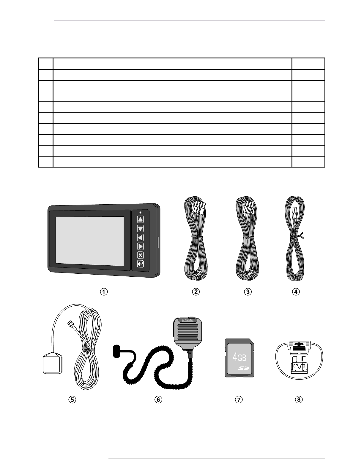
Scope of Supply
№ Description Qty
1 AutoGRAPH-INFO-TFT informational display 1 pc.
2 Power supply cable (primary) 1 pc.
3 6-pin RS-485 cable
1
1 pc.
4 4-pin loudspeaker cable
1
1 pc.
5 GPS/GLONASS antenna
2
1 pc.
6 Push-to-talk (PTT) switch 1 pc.
7 MicroSD, 4 GB 1 pc.
8 1A fuse with a holder 1 pc.
9 Warranty certicate 1 pc.
1
Optional, on request.
2
Related to the modication with an external antenna.
Fig.1. Scope of supply.
Page 9
AutoGRAPH-INFO-TFT • USER MANUAL
9
TechnoKom © 2016
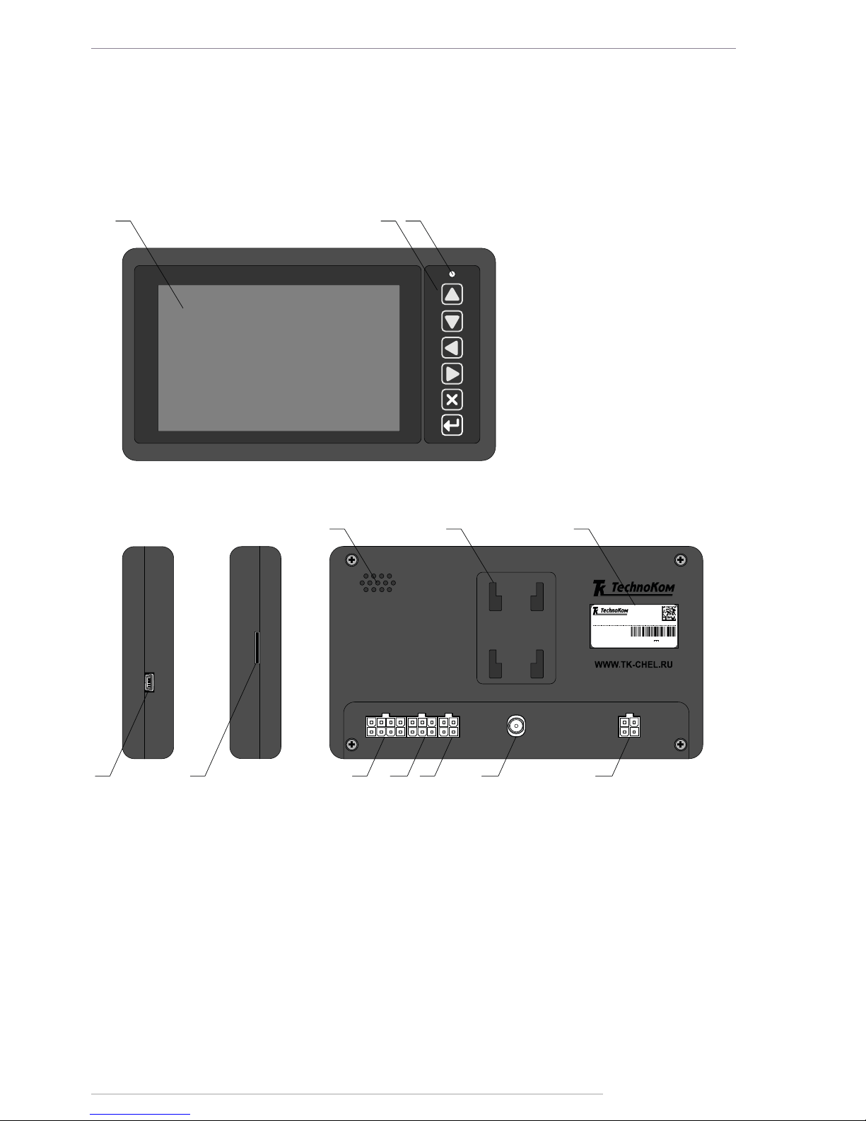
Components of AutoGRAPH-INFO-TFT
1 2 3
4 5 9 10
11
6 7 8
12
Model: AutoGRAPH-INFO-TFT
0362000
S/N
01/20 16
.... ..
Made in Russia
T
echno Kom Ltd .
DC 1 0...6 0V
190 0 mA
13
1. TFT Display.
2. Control buttons1.
3. LED.
4. Mini USB connector.
5. MicroSD slot.
6. Speaker.
7. Holder mounting holes.
8. Manufacturer’s label.
9. Power connector.
10. RS-485 interface connector.
11. Loudspeaker interface connector.
12. GLONASS/GPS antenna connector.
13. PTT switch interface connector.
Fig.2. AutoGRAPH-INFO-TFT components.
Main
Page 10
AutoGRAPH-INFO-TFT • USER MANUAL
10
TechnoKom © 2016
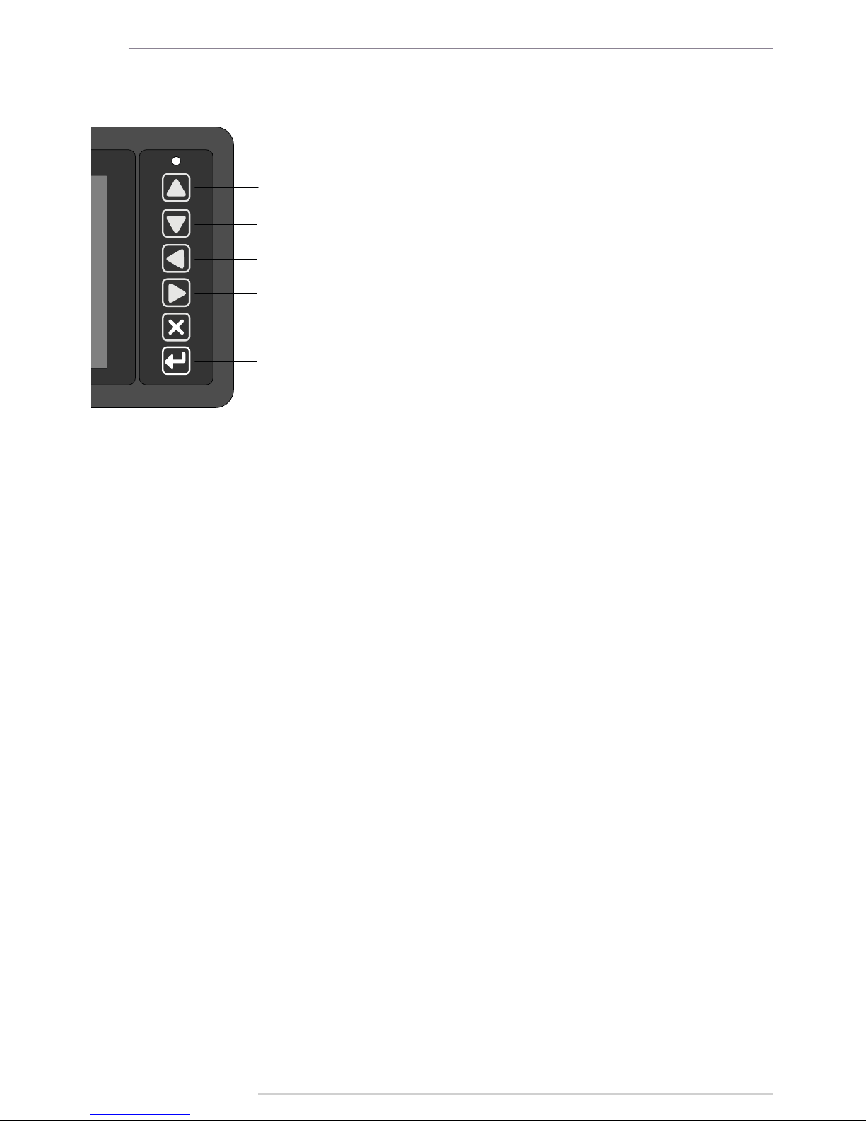
Buttons on front panel
1
2
3
4
5
6
1. U P.
2. DOWN.
3. LEFT.
4. RIGHT.
5. CANCEL.
6. SELECT.
Page 11
AutoGRAPH-INFO-TFT • USER MANUAL
11
TechnoKom © 2016
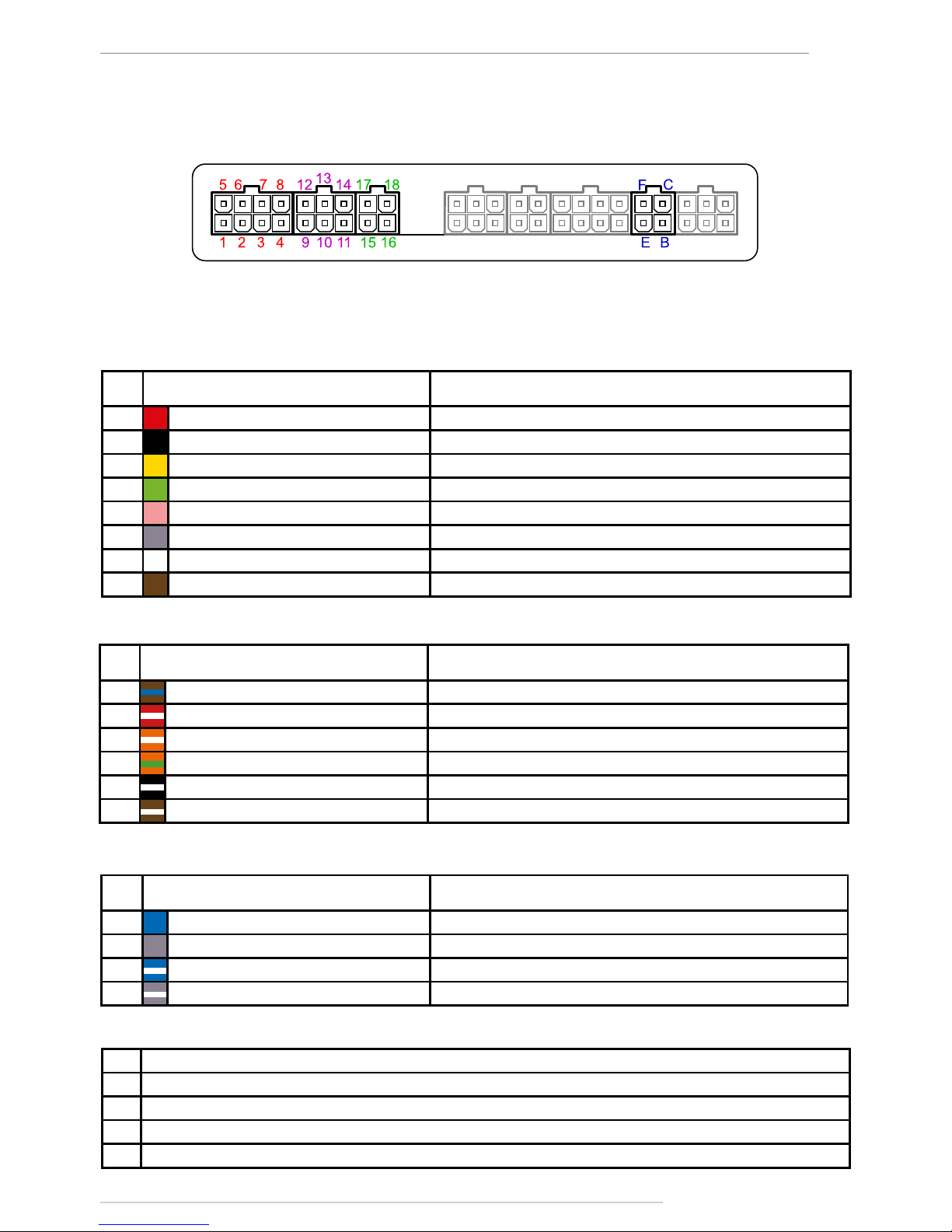
Interface Connectors
Power connector (primary)
№
Colour of a wire in a cable
Assignment
1 Red «+» Vin
2 Black «-» Vin
3 Yellow Digital input 2 (active high)
4 Green «+» Digital input 1
5 Pink High-impedance digital input
6 Grey Open collector output 1 (0.5 A)
7 White Digital input 3 (active high)
8 Brown «-» Digital input 1
4-pin loudspeaker interface connector
№
Colour of a wire in a cable
Assignment
15 Blue «+» Left loudspeaker
16 Grey «+» Right loudspeaker
17 Blue with a white stripe «-» Left loudspeaker
18 Grey with a white stripe «-» Right loudspeaker
6-pin RS-485 interface connector
№
Colour of a wire in a cable
Assignment
9 Brown with a blue stripe RS-485-1 (A): display board interface
10 Red with a white stripe RS-485-2 (A): camera interface
11 Orange with a white stripe RS-485-3 (A) AutoGRAPH controller interface
12 Orange with a green stripe RS-485-1 (B): display board interface
13 Black with a white stripe RS-485-2 (B): camera interface
14 Brown with a white stripe RS-485-3 (B): AutoGRAPH controller interface
Audio connector
ID Assignment
B Microphone signal input
C Not used
E Ground
F Call / Answer button input
* Highlighted grey are connectors not used in the current hardware version of AutoGRAPH-INFO-TFT.
Fig.3. Interface connectors.
Page 12
AutoGRAPH-INFO-TFT • USER MANUAL
12
TechnoKom © 2016
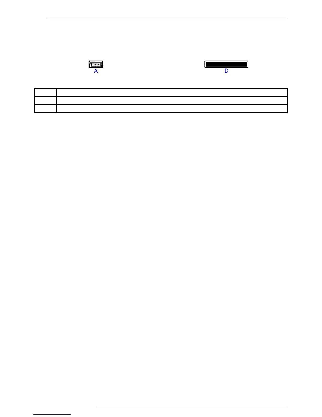
Additional connectors
On the left side panel On the right side panel
ID Assignment
А Mini USB connector (programming / conguration)
D Micro SD slot
Connection diagrams of AutoGRAPHINFO-TFT
This section covers connection procedures of AutoGRAPH-INFO-TFT
• Power supply connection
• Digital inputs / outputs connection
• Connection to the AutoGRAPH onboard controller.
• RS-485 bus connection.
• Connection of a loudspeaker and PTT switch.
Full capacity of AutoGRAPH-INFO-TFT is provided when it is connected to the AutoGRAPH
on-board controller. AutoGRAPH-INFO-TFT can be connected to any AutoGRAPH on-board
controller which is equipped with RS-485 bus.
Connection to the AutoGRAPH controller allows AutoGRAPH-INFO-TFT to send data to
server and exchange SMS with a dispatcher.
Before connecting AutoGRAPH-INFO-TFT to AutoGRAPH controller, GPS/GLONASS and
GSM antennas must be connected to the controller according the instructions given in the
User Manual of the AutoGRAPH controller.
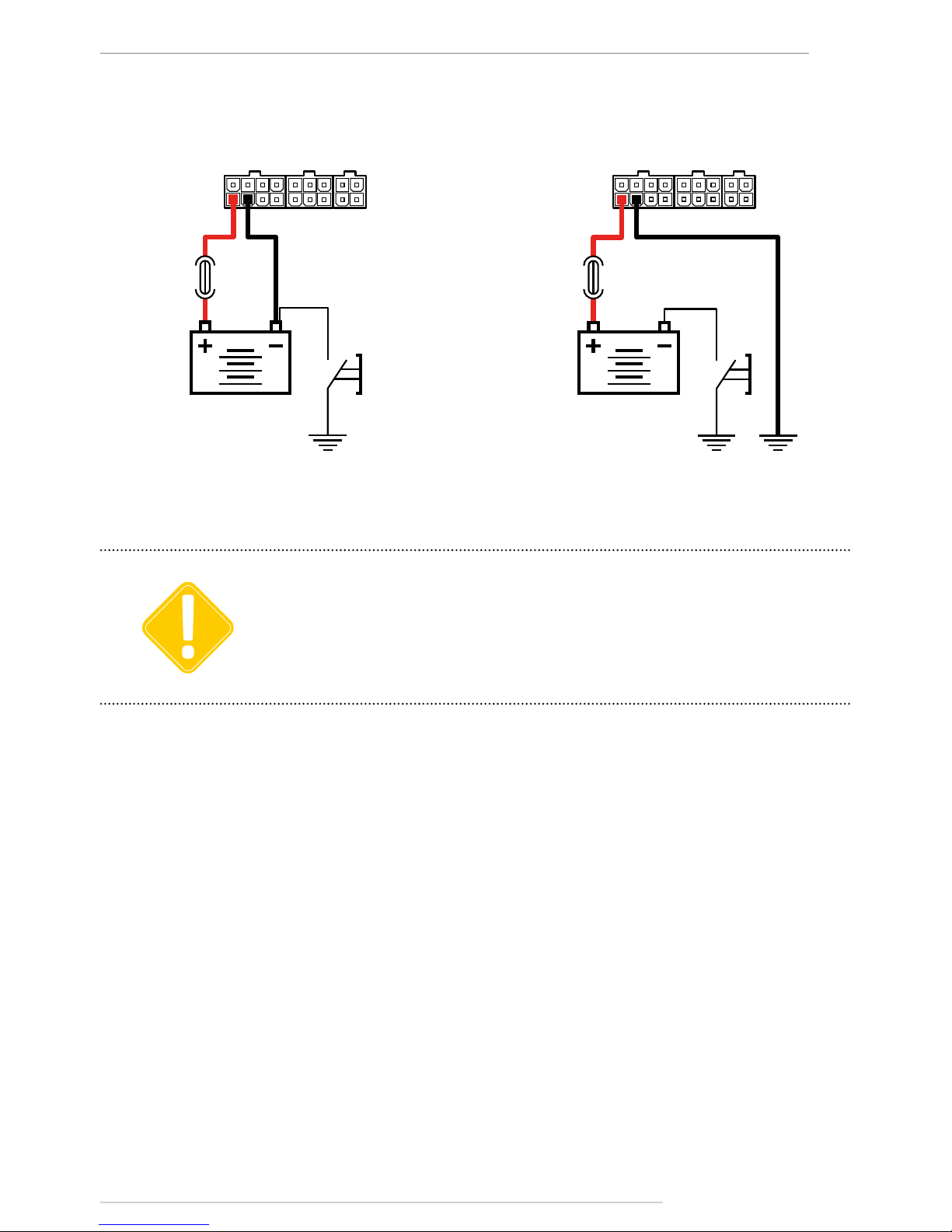
POWER SUPPLY CONNECTION
The AutoGRAPH-INFO-TFT is connected to the power supply source through the primary
interface cable supplied with the device. Also the AutoGRAPH-INFO-TFT is supplied with a
fuse intended to provide a short circuit protection of power supply driver. The fuse holder is
installed on a wire ring, which should be cut before installation.
When making connections, pay special attention to the safety rules stipulated by the
regulations for motor vehicle repair procedures. All connections should be properly isolated
and securely connected. If the wire is too short, it can be spliced with a wire of at least 0.5
mm2 cross section (20 AWG or thicker).
The power supply input of the AutoGRAPH-INFO-TFT is rated for the vehicle system operating
voltage of 10-60 V DC. The pin 1 of the device Power connector must be connected to 12 or
24 V of vehicle operating voltage through a fuse rated for at least 1 A.
Fig.4. Additional connectors.
Page 13
AutoGRAPH-INFO-TFT • USER MANUAL
13
TechnoKom © 2016
RED (1) BLACK (2)
DISCONNECTING
SWITCH
RED (1) BLACK (2)
DISCONNECTING
SWITCH
Fig.5. Power connection before the vehicle battery
disconnecting switch.
Fig.6. Power connection after the vehicle battery
disconnecting switch.
The fuse should be placed as close as possible to the point where the AutoGRAPH-INFO-TFT is
connected to the vehicle power system.
IMPORTANT
The scheme of power supply connection to the AutoGRAPH-INFO-TFT depends on the
power supply connection to AutoGRAPH controller. So power can be fed to the display either
before or after the vehicle’s battery disconnecting switch:
Page 14
AutoGRAPH-INFO-TFT • USER MANUAL
14
TechnoKom © 2016
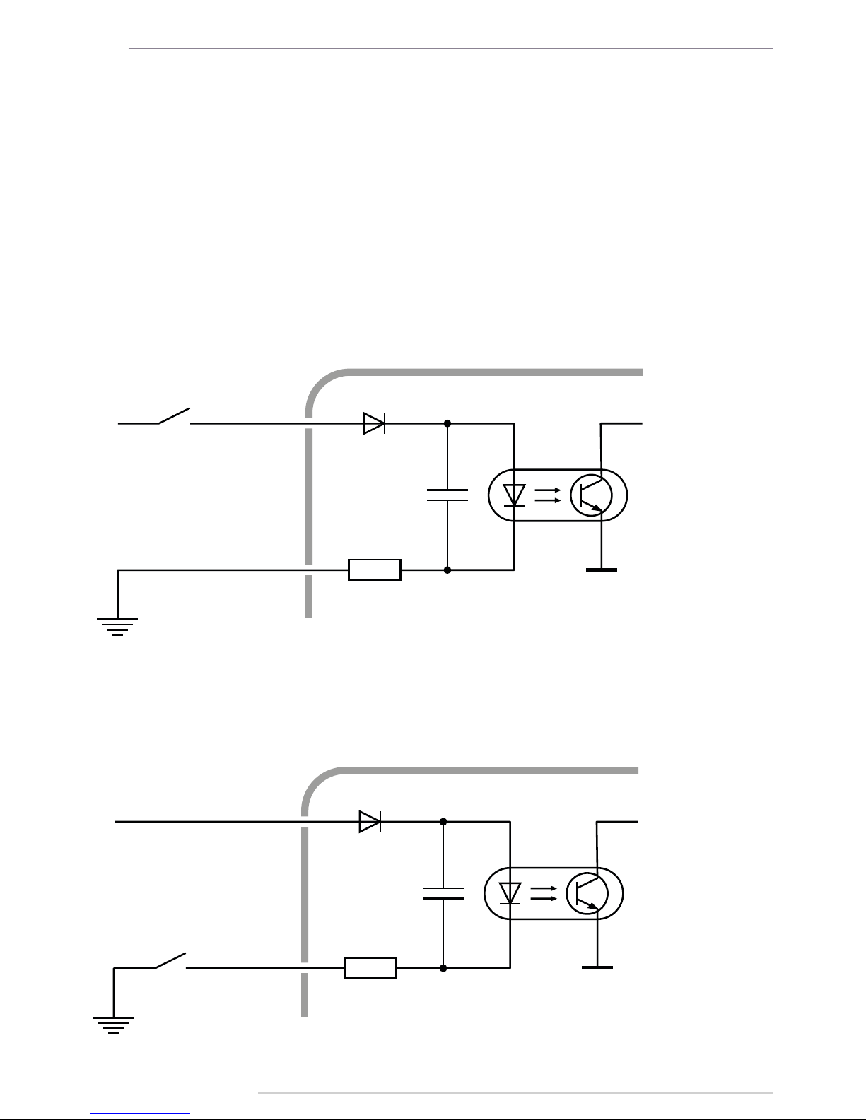
DIGITAL INPUT 1 («+» DIGITAL INPUT 1 AND «-» DIGITAL INPUT 1)
AutoGRAPH-INFO-TFT is equipped with a digital input which logic of operation depends on
how an external device is connected to the input (Input 1).
Depending on the connection diagram the Input 1 may operate as active low input or active
high one.
The input is able to show change of the input state and intended to connect various dry
contact sensors, e.g. door limit switches or any button.
Internal Connection Diagram of Input 1:
Variant 1
This type of connection provides that the input is in active state (logical 1) when it is connected
to +Vin.
+INPUT 1
-INPUT 1
AutoGRAPH-INFO-TFT
+V
in
LIMIT SWITCH
OR SENSOR
LIMIT SWITCH
OR SENSOR
+V
in
+INPUT 1
-INPUT 1
AutoGRAPH-INFO-TFT
Fig.7. Digital input 1 connection diagram. Variant 1.
Fig.8. Digital input 1 connection diagram. Variant 1.
Variant 2
This type of connection provides that the input is in active state (logical 1) when it is connected
to -Vin.
Page 15

AutoGRAPH-INFO-TFT • USER MANUAL
15
TechnoKom © 2016
LIMIT SWITCH
OR SENSOR
AutoGRAPH-INFO-TFT
ACTIVE HIGH
DIGITAL INPUT
+V
in
Internal Connection Diagram of Active High Digital Input:
Fig.9. Connection diagram of digital inputs 2 and 3.
CONNECTION OF HIGH-IMPEDANCE DIGITAL INPUT
AutoGRAPH-INFO-TFT is equipped with a digital high-impedance input: pin 5 on the Power
connector.
High-impedance active high digital input is intended to connect a device with a voltage output
to the display, e.g. a voltage output temperature sensor.
The high-impedance input has two states:
• logical “1” – when the input voltage is greater than 7 V;
• logical “0” – when the input voltage is lower than 3 V.
If the high-impedance input is open-circuit it shall denote logical “0”.
The input resistance of the high-impedance input is 1 mega-ohm (1MΩ).
The cut-off frequency of the input low-pass lter is 5,000 Hz.
DIGITAL INPUTS 2 AND 3
AUTOGRAPH-INFO-TFT is equipped with two active high digital inputs: pin 3 and pin 7 on
the Power connector.
Active high digital input has two states:
• logical «1», when the input is powered by supply voltage. This state is considered to be
active.
• logical «0», when the input is connected to the ground or open-circuit.
It should be noted that all voltage levels of active high digital inputs under 5 V will be
considered to be logical zero (‘ground’), while all voltage levels above 6 V shall be considered to
be logical «1» (active). If the input is open-circuit it shall denote logical «0» .
i
NOTE
Page 16
AutoGRAPH-INFO-TFT • USER MANUAL
16
TechnoKom © 2016
Internal Connection Diagram of High-impedance Input:
R
1 MОhm
AutoGRAPH-INFO-TFT
HIGH-IMPEDANCE
DIGITAL INPUTTo votage
output device
Fig.10. Connection diagram of high-impedance input.
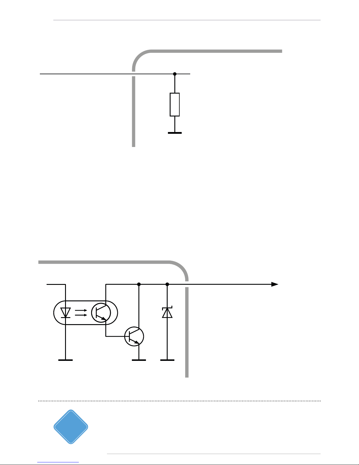
DIGITAL OUTPUT
AutoGRAPH-INFO-TFT is equipped with a digital open-collector output: pin 6 on the Power
connector.
The output is intended to control various external actuators, as well as to activate warning
devices.
Minimum recommended load current is 10 mA.
Maximum load current should not exceed 500 mA.
Internal Connection Diagram of Output:
AutoGRAPH-INFO-TFT
DIGITAL OUTPUT
Fig.11. Digital output connection diagram.
The current version of AutoGRAPH-INFO-TFT rmware does not support control of the digital
output.
i
NOTE
Page 17
AutoGRAPH-INFO-TFT • USER MANUAL
17
TechnoKom © 2016
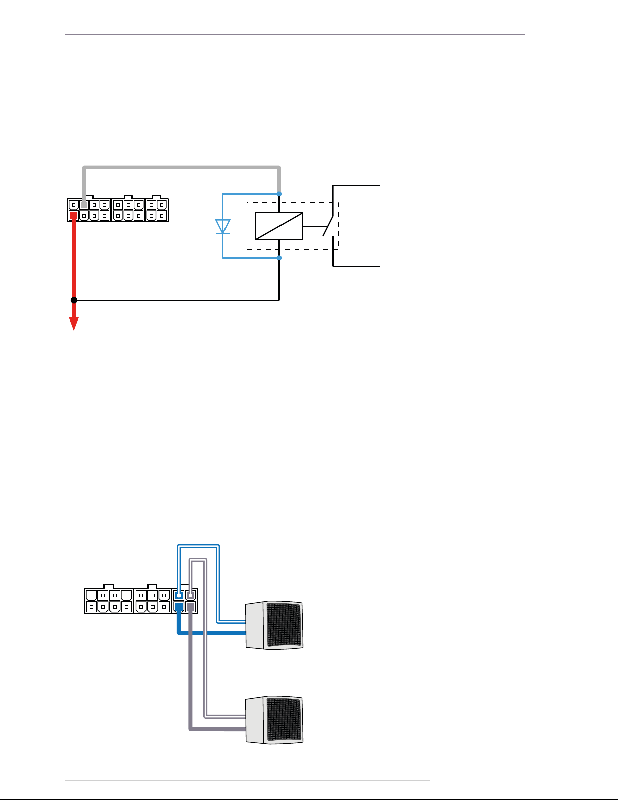
LOUDSPEAKER CONNECTION
AutoGRAPH-INFO-TFT is equipped with two audio outputs intended to connect loudspeakers
to the display, e.g. loudspeakers installed in the passenger compartment.
Pins intended for connecting the loudspeakers are arranged on the 4-pin loudspeaker
interface connector: pin 15 and pin 17 are intended for connection of left loudspeaker, pin 16
and pin 18 – for right loudspeaker.
Minimum load resistance must be at least 4 Ohm. Maximum load resistance must not exceed
16 Ohm.
Connection Diagram of Loudspeaker:
+ +
- -
AutoGRAPH-INFO-TFT
Left loudspeaker
Right loudspeaker
Fig.13. Loudspeaker connection diagram.
OUTPUT 1 – GRAY
RED (1)
TO VEHICLE SYSTEM POWER
PROTECTIVE DIOD
RELAY
TO ACTUATOR
AutoGRAPH-INFO-TFT
External Connection Diagram of Digital Output:
The following is an example of a relay connected to the display output. To avoid damage
of the display output due to back EMF, induced from disconnecting an inductive load,
connect a protective diode in parallel to the relay. To select a correct diode, make sure
that direct current of this protective diode is at least 1.5 times greater than the relay
holding current.
Fig.12. Digital output connection diagram.
Page 18

AutoGRAPH-INFO-TFT • USER MANUAL
18
TechnoKom © 2016
RS-485 BUS
RS-485 is one of the most commonly used industrial standards of communication. A network
based on an RS-485 interface consists of transceivers connected with twisted pair wires. All
devices are connected to one twisted pair in the same manner: non-inverting outputs (A) to
one wire and inverting outputs (B) to another wire.
AutoGRAPH-INFO-TFT is equipped with 3 RS-485 buses, each of them is intended for
connection of specic devices. This can be taken into account when making the connection
because if incompatible device is connected to RS-485 bus, proper operation of that device
is not provided.
Given below is description of RS-485 buses assignment:
• RS-485-1 bus is intended for connection of display boards supported by AutoGRAPHINFO-TFT.
• RS-485-2 is intended for connection of photo cameras.
• RS-485-3 is intended for connection of the AutoGRAPH onboard controller and sensors
supporting LLS protocol.
RS-485 interface pins are arranged on the 4-pin RS-485 connector.
Detailed information on how to congure AutoGRAPH-INFO-TFT for operation with display
boards, photo cameras, the AutoGRAPH onboard controller, and fuel level sensors via RS485 bus is given in following sections of this document.
i
NOTE
Connection to PC
Some cases may require connection of the AutoGRAPH-INFO-TFT device to a personal
computer (PC) or a laptop, e.g. for conguration using the DisplayCongure application.
The AutoGRAPH-INFO-TFT is connected to a PC using standard AM – USB mini B 5pin
Data-cable.
To connect the AutoGRAPH-INFO-TFT to a PC:
• Disconnect the device from vehicle power supply and external devices.
• Connect the device to PC using Data-cable.
• If the required drivers are installed, the system will automatically identify the connected
device. If the drivers are not installed, install them following the steps specied in the «Drivers
installation» section. Now the device is ready to operate with the applications.
Page 19
AutoGRAPH-INFO-TFT • USER MANUAL
19
TechnoKom © 2016
AutoGRAPH-INFO-TFT configuration
tool
Using the DisplayCongure software, you can set up AutoGRAPH-INFO-TFT. This software
allows you to congure the display for operation with external devices, edit templates of
standard messages and etc.
For proper operation of the DisplayCongure software, the .NET Framework 4.0 package
(supplied) is required.
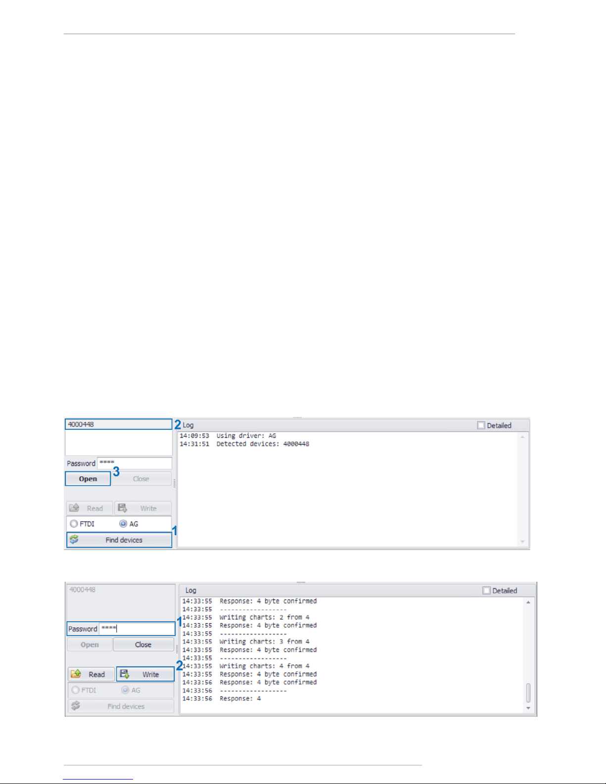
To set up AutoGRAPH-INFO-TFT:
• connect power supply to the display;
• connect the display to a PC following the instruction given in section “Connect to PC”;
• run the DisplayCongure software;
• on the DisplayCongure software, press the “Find devices” button (Fig.14, i.1) to search
for the connected devices;
• select serial number of the required device in the list of available devices (Fig.14, i.2) and
press the «Open» button (Fig.14, i.3). If the option «Read conguration automatically» is
enabled, the device settings will be read in the application. If the settings haven’t been read
automatically, press the «Read» button;
• set up necessary settings on the software tabs;
• enter the device password in the «Password» eld (Fig.15, i.1), then press the «Write»
button (Fig.15, i.2) to save the specied settings in the connected device;
Fig.14. Connect the display to PC.
Fig.15. Save settings in the display.
Page 20
AutoGRAPH-INFO-TFT • USER MANUAL
20
TechnoKom © 2016
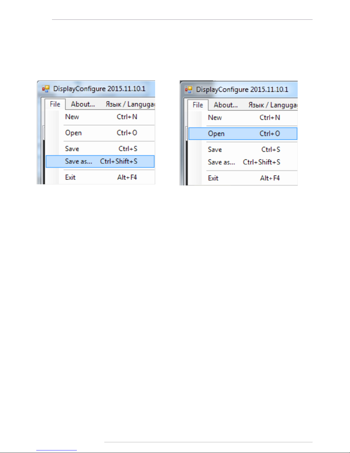
Export conguration from external le
Device conguration can be exported in the le of .dcong format and then used to set similar
settings in several devices. To save the settings to external le, select Main menu/File/Save
as... (Fig.16) in the DisplayCongure tool. To load a conguration le in the DisplayCongure
application, select Main menu/File/Open (Fig.17).
Fig.16. Save conguration. Fig.17. Open conguration.
Page 21
AutoGRAPH-INFO-TFT • USER MANUAL
21
TechnoKom © 2016
Getting started
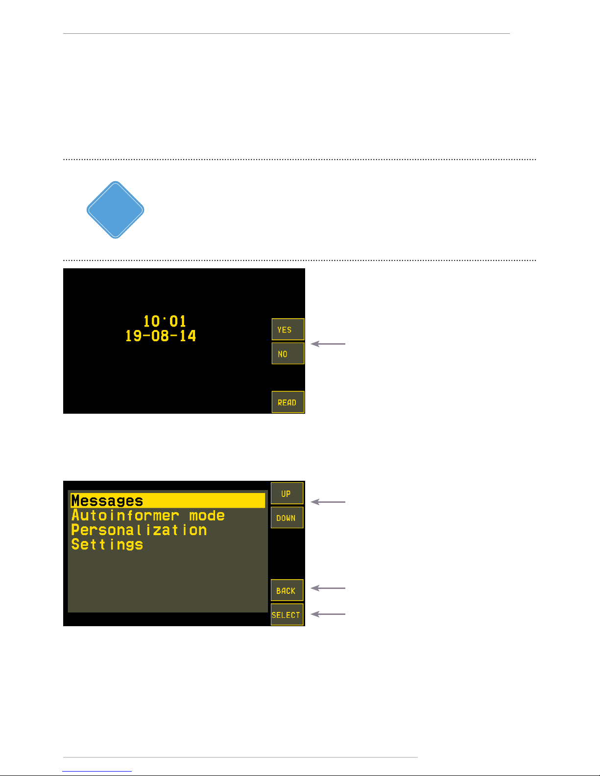
AutoGRAPH-INFO-TFT turns on immediately after connecting it to power supply source. If
AutoGRAPH-INFO-TFT is connected to the AutoGRAPH on-board controller, it will display
the current time on the main screen after the turning on (Fig.18). As AutoGRAPH-INFO-TFT
is equipped with real-time clock, the current time will be taken from the timer if the device is
not connected to the AutoGRAPH controller.
Fig.18. Main screen
Press to send quick messages.
Buttons “Yes” and “No” on the main screen allows you to send quick replies “Yes” or “No” to a
dispatcher. These buttons are available only when the Custom prole of messages is set up.
The MENU button is intended to go to the device main menu.
Fig.19. Main menu.
Use these buttons to browse the menu
Press to return to the Main screen
Press to go to the selected menu
In the Main menu to go to any section of the menu, you need to select it using the UP and
DOWN buttons, then press the SELECT button. You also can tab the required item of the
menu to select it.
Similar to the SELECT button press, double click a menu opens it.
Also you can use control buttons on the front panel of AutoGRAPH-INFO-TFT to browse the
menu and select necessary items. Capability of the buttons on the front panel depends on the
active menu and are displayed on the device screen.
For the rst start, the time 05:00 will be set up in the device, if it is not connected to the
AutoGRAPH controller. To adjust current time, go to the Main menu/Settings/Local time.
More detailed information on how to set up the device time is given in the section «General
settings» of this document.
i
NOTE
Page 22
AutoGRAPH-INFO-TFT • USER MANUAL
22
TechnoKom © 2016
Status bar at the top of the main screen contains icons intended to indicate vehicle operation:
GSM signal level, navigation state and GSM modem error codes.
Described below is GSM modem error codes:
Error code Description of error
PWR Bad power of GSM modem or failure of GSM modem power supply monitor
MOD GSM modem does not response
SIM SIM is not inserted or unknown SIM error
PIN PIN error
PUK PUK is required
REG Data transmission is required, but no data is transmitted for a long time
Data transmission capability is unavailable for a long time
Unable to connect to GSM network
NET GPRS status is unavailable for a long time
Multiple errors occurred when enabling GPRS
Multiple errors occurred when connecting to data server
Connection to server is unavailable for a long time
Connection to server is established, but data transmission is not initialized
OPR Data transmission is disabled by mobile operator
SRV The device is not serviced by the server
Invalid server password
Special-purpose key combinations
Using combinations of buttons described below you can enable special functions of the
display. Only buttons on the display front panel can be used for this purpose.
• UP+DOWN – displays the device rmware version on the main screen.
• CANCEL+ENTER – sends alarm signal (see section “Alarm signal”).
• CANCEL+UP+DOWN – sets default settings in the display. This combination is available
within 20 seconds after the device turning on.
• CANCEL+UP – resets Accumulable counters which have been preset in the device.
Statuses indicated on the status bar are received from the AutoGRAPH controller. Transmission
of operation statuses via RS-485 is supported by AutoGRAPH controllers with rmware of
version AGXL-11.62 and higher.
i
NOTE
Page 23

AutoGRAPH-INFO-TFT • USER MANUAL
23
TechnoKom © 2016
General settings
To set preferences of AutoGRAPH-INFO-TFT such as screen brightness, key tones, interface
language, and etc., select Main menu/Personalization.
Fig.20. Personalization menu.
To tune display brightness of the device,
you need to go to the Brightness and
volume menu, then select the Display
brightness option using the UP and
DOWN buttons. To set the required
brightness level, use buttons «<<» and
«>>» then save the selected setting
pressing the SAVE button.
To tune volume of the display sounds,
you need to go to the Brightness and
volume menu,then select the Volume
option using the UP and DOWN buttons.
Fig.21. Brightness and volume.
Brightness and Volume
To select colour of the display menus,
go to the Colour skin menu. When you
select a colour skin, it is applied to the
current menu in order to show a preview.
To apply the selected skin to the device
completely, press the SAVE button. To
turn to last saved skin and exit from
the Colour skin menu, press the BACK
button.
Fig.22. Colour skin.
To set the required volume level, use buttons «<<» and «>>» then save the selected setting
pressing the SAVE button.
Colour skin
Page 24

AutoGRAPH-INFO-TFT • USER MANUAL
24
TechnoKom © 2016
Key tone
To set up a type and duration of the device key tone, you need to go to the Key tone menu.
There are two sections:
• Tone duration is intended to select duration of the tone: short, medium, long or none
(disables key tones).
• Tone frequency is intended to select frequency (in Hz) of the tone.
Fig.23. Tone duration. Fig.24. Tone frequency.
Before you apply the selected tone setting, you can do a test. To do it, select the required
item – frequency or duration using the UP and DOWN buttons, and press the TEST button.
Then try to press the device buttons.
In order to save the selected settings, press the SELECT button.
Select language
Fig.25. Interface language.
To select AutoGRAPH-INFO-TFT interface
language, you need to go to the Select
language menu then select a language
using Up and DOWN buttons. To apply
settings, press the SELECT button.
The selected language will be set without
device restart.
Date and time
It is recommended to set date and time in the device according to its location. To adjust date
and time, select Main menu/Settings/Local time.
Fig.26. Time zone. Fig.27. Date and time.
Page 25

AutoGRAPH-INFO-TFT • USER MANUAL
25
TechnoKom © 2016
• To set up the device time zone in the form of a GMT offset, use the buttons “<<” and “>>”.
E.g. the offset +05 is a time zone used in following countries: Maldives, Pakistan, Tajikistan,
Turkmenistan, Uzbekistan.
• Local time zone is only used to display time on the main screen. In other device menus,
data is displayed in GMT. Also the display records data in an internal memory in GMT. This
feature can be locked in order to provide data recording in local time (see the section “Lock
device functions” for more detailed information).
• Use the YES/NO button to enable/disable the Daylight Saving Time.
• To set up current date and time, press the More+ button in the Local time menu (Fig.26).
This will enable additional buttons (Fig.27). Then, you need to select a value to edit using the
buttons “>>” and “<<”. As the value is selected, use the CHNG+ button to increase it or use
the CHNG- button to decrease the value.
• To apply new time settings, press the SAVE button.
Settings protection
AutoGRAPH-INFO-TFT settings are protected with a password which can be from 4 to 8
characters long. This password is required in order to change the device settings using the
DisplayCongure software or get an access to the Settings menu of AutoGRAPH-INFO-TFT
which contains main operation conguration of the device.
When you try to open the Settings menu, the device requests password (Fig.28).
If AutoGRAPH-INFO-TFT is not equipped with an internal real-time clock, time tuning
is unavailable, that’s why the More+ button is hidden. That device will receive current
time from the connected AutoGRAPH controller. If no AutoGRAPH controller is connected,
AutoGRAPH-INFO-TFT will display default time 05:00.
IMPORTANT
Fig.28. Password request.
To enter password:
• select rst character of the password using the CHNG+ and CHNG- buttons;
• as the rst character is entered, press the button “>>” to go to the second character. If you
need to edit a character that is already entered, use the button “<<” to return the cursor to
that character position.
• enter other characters of the device password in a similar way;
Page 26

AutoGRAPH-INFO-TFT • USER MANUAL
26
TechnoKom © 2016
Fig.29. New password setup.
Voice communication
AutoGRAPH-INFO-TFT provides voice communication function intended for a driver to
communicate with passengers.
AutoGRAPH-INFO-TFT is equipped with the 4-pin audio connector intended to connect PTT
switch, which is supplied with the display.
When driver presses the Answer/Call button on the PTT switch, the display turns on the
loudspeaker amplier and the communication becomes available.
During the communication the sound level can be adjusted by changing the distance to the
microphone.
In addition to voice communication initiated by driver, AutoGRAPH-INFO-TFT also provides
automatic voice announcement of public transport stops and other preset advertisements
in the Auto informer mode. The automatic announcements can be interrupted by voice
messages transferred by driver. If the automatic announcement is interrupted that way, its
playback is not continued after nishing the driver’s message.
• as the password has been entered completely, press the SELECT button. If the password
is correct, you will get an access to the Settings menu. Otherwise, the device will inform you
about incorrect password and return to the main menu.
Default password of AutoGRAPH-INFO-TFT that is set by the manufacturer is «0000». It is
highly recommended to change default password to more reliable one in order to prevent
unauthorized access to the device settings.
To change the device password:
• select Main menu/Settings/Change password. To access the Settings menu, enter the
device current password (Fig.29);
• in the New password line, enter a new password in the same way as you enter password
to access to the Settings menu (see above). The password can be from 4 to 8 characters
long and contain gures from 0 to 9 and uppercase letters of Latin alphabet. The password
characters are to be entered one by one. To select a character value from the list of available
symbols, press the CHNG+ and CHNG- buttons until the required symbol is entered. To
move to next character, press the button “>>”. To return to previous character, press the
button “<<”. To apply the password, press the SELECT button;
Page 27

AutoGRAPH-INFO-TFT • USER MANUAL
27
TechnoKom © 2016
Alarm signal
In an emergency you can send alarm signal to a dispatcher. To do it, press simultaneously the
CANCEL and ENTER buttons on the device front panel and hold the buttons until the alarm
sound (3 short, 3 long then 3 short beeps). After that AutoGRAPH-INFO-TFT will send the
message “SOS!!!” with the current position coordinates.
Photo cameras connection
AutoGRAPH-INFO-TFT supports connection of up to 16 photo cameras in order to get visual
information on a vehicle operation.
All cameras must be connected to RS-485-2 bus of AutoGRAPH-INFO-TFT.
The current version of AutoGRAPH-INFO-TFT rmware supports operation with the ZM-CAM
Series photo cameras by Shenszhen Quick Zoom Technology Co., Ltd (www.zmvideo.com).
The cameras of this series record photos in JPEG format and are equipped with the infrared
lighting and serial RS-485 bus providing 115200 bit/s baudrate.
The cameras require operating voltage within the range 9...30 V.
Shown on Fig.31 are the different design versions of the ZM-CAM Series cameras.
Fig.30. The ZM-CAM Series cameras.
Starting with the rmware of version AGDS-04.09, AutoGRAPH-INFO-TFT supports operation
with photo cameras by Shenszhen Quick Zoom Technology Co., Ltd providing 1.3 megapixels
resolution. The instruction on how to set up AutoGRAPH-INFO-TFT to receive photos from
that type of cameras is given below.
Page 28

AutoGRAPH-INFO-TFT • USER MANUAL
28
TechnoKom © 2016
Connection diagram of photo cameras
The cameras must be connected to the RS-485-2 bus of AutoGRAPH-INFO-TFT which is
arranged on the 6-pin RS-485 interface connector: pin 10 is A line, pin 13 is B line.
«A» «B»
CAMERA 1
«A» «B» «A» «B»
...
AutoGRAPH-INFO-TFT
RS-485-2 «B» (13)
BLACK WITH A WHITE STRIPE
RS-485-2 «A» (10)
RED WITH A WHITE STRIPE
CAMERA 2 CAMERA N
Fig.32. Connection diagram for photo cameras.
All cameras must be connected to AutoGRAPH-INFO-TFT by means of the CAM-splitter
produced by TechnoKom Ltd. and intended for photo cameras supporting JPEG format.
Congure AutoGRAPH-INFO-TFT to operate with photo cameras
For proper operation of AutoGRAPH-INFO-TFT with photo cameras, it must be correctly
congured using the DisplayCongure software.
To congure AutoGRAPH-INFO-TFT to operate with photo cameras:
• open the DisplayCongure software and go to the External devices tab;
Fig.31. Cameras set up in the
DisplayCongure software.
Page 29

AutoGRAPH-INFO-TFT • USER MANUAL
29
TechnoKom © 2016
• all cameras connected to the display and their settings must be specied in the table
on the tab. To add a new camera, click the empty row at the top of the table, then specify
following settings according the technical characteristics on the camera:
Name – the camera name. The name can be up to 20 characters long and is displayed in
AutoGRAPH-INFO-TFT to identify the camera;
Address – a network address of the camera;
Resolution – camera resolution. You need to select a resolution from the drop-down list of
available values.
Compression – JPEG compression rate. Minimum value is 20, maximum value is 250. The
higher the compression rate, the smaller a photo size.
Flags – select events initiating extra photo recording in the drop-down list. This list contains
events of the AutoGRAPH onboard controller:
• Input 1-Input 8 – enables extra photo record when the selected digital inputs of the
AutoGRAPH controller trigger.
• iButton – enables extra photo record by iButton registration.
• Event 10 – enables extra photo record by triggering the high-impedance digital input
of AutoGRAPH-INFO-TFT (pin 5 on the Power connector), when the input switches from
logical 0 level to logical 1 level.
• Event 11 – enables extra photo record by triggering the high-impedance digital input
of AutoGRAPH-INFO-TFT (pin 5 on the Power connector), when the input switches from
logical 1 level to logical 0 level.
• Event 12-Event 16 – reserved.
For photo cameras with 1.3 megapixels resolution the compression must not
exceed 90. The recommended values – from 20 to 90.
IMPORTANT
Period – a period of automatic photo recording. Minimum value is 15, maximum value is
65000, 0 period disables periodic recording of photos from the camera.
While setting cameras, pay special attention to the limitation that the period
of automatic photo recording must not be smaller than the time interval
taken to read a photo from camera, e.g. this parameter can amount up 10
seconds for the high quality coloured photo with VGA resolution.
IMPORTANT
Also it should be taken into account that AutoGRAPH-INFO-TFT records
photos from cameras sequentially, that’s why the record of next photo can be
delayed by processing the previous photo from RS-485 bus.
IMPORTANT
Page 30

AutoGRAPH-INFO-TFT • USER MANUAL
30
TechnoKom © 2016
To provide automatic photo recording by the AutoGRAPH controller digital input triggering,
it is not sucient to set up AutoGRAPH-INFO-TFT. You also need to enable data transmission
via RS-485 bus by the input triggering in the AutoGRAPH controller for the digital input that
is used. This option can be set up using the AG.GSMConf software intended to congure
AutoGRAPH onboard controllers. To set up the controller’s digital inputs, you need to go to the
Inputs tab of the AG.GSMConf software.
IMPORTANT
• as all cameras specied, save the settings.
Change camera address in AutoGRAPH-INFO-TFT
To simplify cameras installation on a vehicle or their replacement, you can change cameras
hardware addresses using AutoGRAPH-INFO-TFT. This avoids the necessity for cameras
reconguration and allows using the range of addresses that has been already sent in
AutoGRAPH-INFO-TFT.
To change a camera hardware address:
• disconnect all cameras from AutoGRAPH-INFO-TFT;
• turn on AutoGRAPH-INFO-TFT and select Main menu/Settings/Camera/Change cam.
address (Fig.33);
• connect only one camera to the display and select its address using the buttons “<<” and
“>>”. Name of connected camera and the selected address are shown on the display;
• as address is selected, press the SAVE button.
Fig.33. Change of camera address. Fig.34. Setup of camera address.
It is highly important that only one camera is connected to AutoGRAPH-INFO-TFT
when you change its hardware address. Otherwise correct setup of the address is not
available.
IMPORTANT
Page 31

AutoGRAPH-INFO-TFT • USER MANUAL
31
TechnoKom © 2016
Fig.35. Copy photos from FLASH memory.
Photo recording
AutoGRAPH-INFO-TFT scans cameras every ve minutes. If at least one camera is failed, the
display noties a user using sound signal then records a log. Therefore, if AutoGRAPH-INFOTFT produces a long beep every 5 minutes, it is highly recommended to check connected
cameras for integrity.
AutoGRAPH-INFO-TFT records photos from cameras with a regular period if it is specied
or by preset events.
Also the forced record of photo can be made by the command from the AutoGRAPH 5 PRO
Dispatch Software. The Dispatch Software also allows request of photos from the display
memory card.
All photos are stored on SD card inserted in AutoGRAPH-INFO-TFT in the following directory
– \YEAR\MONTH\DAY, e.g. the photo AGDS_0100107_01_120416_102540_00009.jpg
in the directory \\Year_2015\\Mon_04\\Date_16 was taken on the 16th of April in 2015 at
10:25:40, the display serial number is 100107, address of camera recorded the photo is 1,
the photo number is 9.
Apart from that 1,5 MB of internal FLASH-memory of AutoGRAPH-INFO-TFT is dedicated
to store recent photos to allow their recovery in case of damage of them on the SD card. A
number of photos recorded in FLASH-memory depends of their size. If the dedicated memory
is full, a new photo will be recorded instead of the oldest one providing that the most up-todate data is always available.
As necessary, photos from FLASH memory can be copied to the display SD card. To do
it, select Main menu/Settings/Camera/Copy photos to SD in the display. This will copy all
photos from the device FLASH memory to the directory \FLASH_120416 on the SD card (the
“150416” is a date of the copying).
During the copying which can take a few tens of seconds AutoGRAPH-INFO-TFT produces
sound. It is not recommended to remove the device SD card during the copying.
In order to remove photos from the device SD card, a complete formatting of the memory
card is required. To format the SD card select Main menu/Settings/SD card manager/Format
SD (Fig.35).
This will delete all data as well as photos from the device SD card.
Page 32

AutoGRAPH-INFO-TFT • USER MANUAL
32
TechnoKom © 2016
Connection of AutoGRAPH controller
and fuel level sensors.
RS-485-3 bus of AutoGRAPH-INFO-TFT is intended for connection of LLS sensors and the
AutoGRAPH onboard controller.
AutoGRAPH-INFO-TFT supports operation with following AutoGRAPH controller:
AutoGRAPH-GSM, AutoGRAPH-GSM+, AutoGRAPH-SL, AutoGRAPH-WiFi+GSM,
AutoGRAPH-WiFi.
Connection to the AutoGRAPH controller allows AutoGRAPH-INFO-TFT to receive position
data, send text messages to a dispatcher and receive messages and les from data server.
Also AutoGRAPH-INFO-TFT supports connection of LLS sensors to RS-485-3 bus, e.g. fuel
level sensors.
Connected to the AutoGRAPH controller or equipped with LLS sensors AutoGRAPH-INFOTFT can be set up to display data from RS-485-3 on the main screen.
For proper operation of AutoGRAPH-INFO-TFT with external devices via RS-485-3,
you need:
• Connect external device to RS-485-3 of AutoGRAPH-INFO-TFT according to the
connection diagrams given below.
• Set up RS-485-3 of AutoGRAPH-INFO-TFT for interfacing with connected device.
• Set correct main screen mode of AutoGRAPH-INFO-TFT in order for the device to display
data from RS-485-3 bus on the screen. This option can be set in the Main screen menu (for
detailed information, see the section “Main screen” of this User Manual).
• also specify in AutoGRAPH-INFO-TFT a list of parameters which must be displayed
on the main screen. Use the DisplayCongure software to create a list of parameters for
display and save it in AutoGRAPH-INFO-TFT. Detailed information on how to create the
list of parameters is given in the section “Main screen” of this User Manual. The full list of
supported parameters is given in the Appendix 3.
Fig.36. Format SD card.
Page 33

AutoGRAPH-INFO-TFT • USER MANUAL
33
TechnoKom © 2016
AutoGRAPH controller connection diagram
AutoGRAPH-INFO-TFT must be connected to RS-485 Bus of the AutoGRAPH controller. If
the controller is equipped with double RS-485 bus, the display must be connected to RS-4851 Bus of the controller. To make the connection, join pin 11 (line A) and pin 14 (line B) on the
6-pin RS-485 interface connector of AutoGRAPH-INFO-TFT respectively to Line A and Line
B of RS-485 (RS-485-1) of the controller.
«A» «B»
AutoGRAPH-INFO-TFT
RS-485-3 «B» (14)
BROWN WITH A WHITE STRIPE
RS-485-3 «A» (11)
ORANGE WITH A WHITE STRIPE
AutoGRAPH
onboard
controller
Fig.37. Connection to AutoGRAPH controller.
RS-485-3 «B» (14)
BROWN WITH A WHITE STRIPE
+V
in
of sensor
RS-485-3 «A» (11)
ORANGE WITH
A WHITE STRIPE
+V
in
of sensor
+V
in
of sensor
Sensors connection diagram
RS-485-3 of AutoGRAPH-INFO-TFT allows connection of up to 8 LLS sensors with network
addresses within the range 1...8. If the connected sensor has address that is out of the required
range, this sensor won’t be scanned by AutoGRAPH-INFO-TFT. Due to this all sensors must
be properly congured before connection to the display.
Given below is the diagram of connecting the fuel level sensors to AutoGRAPH-INFO-TFT.
Fig.38. Connection of fuel level sensors.
Page 34

AutoGRAPH-INFO-TFT • USER MANUAL
34
TechnoKom © 2016
All connections should be made when the AutoGRAPH-INFO-TFT and all external devices to be
connected to the RS-485 bus are disconnected from power supply.
Be careful not to cross the «A» and «B» wires, otherwise the device connected to the
AutoGRAPH-INFO-TFT may operate incorrectly.
IMPORTANT
RS-485-3 set up
RS-485-3 mode
After making a connection to RS-485-3 bus, you need to set up the mode of RS-485 bus.
To do it, select Main menu/Settings/Control menu/Mode of RS-485-3/Operation mode.
Fig.39. Mode of RS-485-3 bus.
RS-485-3 can operate in one of the following modes (Fig.39):
• operation with AG – this mode must be enabled if the AutoGRAPH onboard controller
is connected to AutoGRAPH-INFO-TFT (via RS-485-3 bus). In this mode the display also
receives data from different sensors connected to the AutoGRAPH controller.
• operation with LLS – this mode must be enabled if AutoGRAPH-INFO-TFT is not
connected to the AutoGRAPH controller. This mode enables data reception from LLS sensor,
as well as fuel level sensors connected to RS-485-3 bus of AutoGRAPH-INFO-TFT.
• receiving mode – this mode enables data reception from RS-485-3 bus and disables data
transmission to the bus. In this mode AutoGRAPH-INFO-TFT only receives data available
on the bus. The receiving mode can be used by one of the AutoGRAPH-INFO devices
connected to the AutoGRAPH controller providing reception and display of that data which
is sent by the controller to other AutoGRAPH-INFO which common RS-485 bus is tuned to
the mode “operation with AG”.
RS-485-3 baudrate
RS-485-3 bus of AutoGRAPH-INFO-TFT must be set to the same baudrate as a baudrate of
RS-485 bus of the AutoGRAPH controller which the display is connected to.
To set up the baudrate in the AutoGRAPH-INFO-TFT select Main menu/Settings/Control
menu/Mode of RS485-3/Baudrate, then select a baudrate from the list of available (Fig.40).
It is not recommended to use a baudrate less than 115200 bit/s if AutoGRAPH-INFO-TFT
downloads les from data server via the AutoGRAPH controller.
Page 35

AutoGRAPH-INFO-TFT • USER MANUAL
35
TechnoKom © 2016
Fig.40. RS-485-3 baudrate.
Page 36

AutoGRAPH-INFO-TFT • USER MANUAL
36
TechnoKom © 2016
Message handling
The AutoGRAPH-INFO-TFT allows a driver to send messages to data server those then
become available for a dispatcher. Also the device can send a message to up to 3 preset
telephone numbers. At the beginning of a message the device sends its current coordinates.
It is available to sent only standard messages grouped according to their subjects.
Select messages prole
To set up a messages prole go to Main menu/Settings/Message prole, then select a prole
(Fig.41).
Following proles are available: Dortransnavigatsiya, Police and Custom. All proles, besides
the Custom prole, are the special purpose proles which are used in specic situations.
Fig.41. Message prole.
For general application it is recommended to use the Custom prole which contains userdened messages. To add a new message in the prole, use the DisplayCongure software.
The custom prole can contain up to 6 different subjects with 8 messages in each of them.
Detailed information on how edit message prole is given in paragraph «Create/Edit list of
standard messages, standard replies, and phone numbers of recipients» of this section.
i
NOTE
Page 37

AutoGRAPH-INFO-TFT • USER MANUAL
37
TechnoKom © 2016
Send messages
To send a standard message, you need to select Main menu/Messages, then select «Send
message» option (Fig.42).
Fig.42. Messages menu.
The AutoGRAPH-INFO-TFT will prompt you to select a topic of standard messages available
in the preset prole (Fig.43), then – a message to send.
Fig.43. List of standard messages.
Fig.44. Message transmission.
Before sending the message, select a recipient using the buttons “<<” and “>>” (Fig.44).
Using the DisplayCongure tool up to 4 recipients can be set up: a dispatcher and other
responsible persons. When recipient is selected, press the SELECT button to transfer the
message.
As the message is transmitted, the status “Message is sent” is displayed on the screen.
Page 38

AutoGRAPH-INFO-TFT • USER MANUAL
38
TechnoKom © 2016
Fig.45. Message transmission is denied.
Using the “LEFT” and “RIGHT” buttons on the device front panel you can send respectively
rst and second messages of the current prole (besides the “Transnavigatsiya” prole). This
feature is available only when the main screen is open.
Also when the Custom prole of messages is enabled you can send quick answer to dispatcher
using the buttons “Yes” and “No” on the main screen (Fig.46).
Receive messages
AutoGRAPH-INFO-TFT is able to receive messages from data server via AutoGRAPH
on-board controller. When the device receives a new message, the notication «SMS n» is
displayed on the device main screen (n – a number of new messages), Fig.46. Furthermore,
the device beeps once a minute.
To read an incoming message, press the READ button on the lower right of the main screen
which is displayed instead of MENU button when there is an unread incoming message.
When incoming message is open (Fig.47), you can scroll the message text using the UP and
DOWN buttons.
Buttons “<<” and “>>” are intended to go respectively to previous and next incoming messages.
The REPLY button is intended to create and send a reply to open incoming message. The
BACK button goes to previous menu.
Transmission of messages can be disabled by locking the function in the device settings.
In this case the user will get a notication “Transmission is disabled” when trying to send a
message (Fig.45). For more detailed information on how to lock or unlock the device functions
see section “Lock device functions” of this document.
Fig.46. Incoming message indication.
Page 39

AutoGRAPH-INFO-TFT • USER MANUAL
39
TechnoKom © 2016
Fig.47. Incoming message.
You can open the incoming messages menu also by selecting Main menu/Messages/
Incoming messages. AutoGRAPH-INFO-TFT can store up to 30 messages in memory using
the ring buffer principle. It means that new message will be written over the oldest message
rst, ensuring that the most recent message is always available.
To send a message to AutoGRAPH-INFO-TFT, it is necessary to send the command
DISPLAY=…; with the required text to AutoGRAPH on-board controller connected to the
display. The command can be sent via data server or by means of SMS to a number of the
SIM installed in the controller. After processing the command, the AutoGRAPH controller will
send the message to AutoGRAPH-INFO-TFT via RS-485 bus.
Format of the command DISPLAY=; must match the format of remote control commands of
the AutoGRAPH on-board controller. More detailed information on remote control commands
is given in the document «AutoGRAPH-GSM. Server and SMS control commands».
IMPORTANT
Incoming messages can be removed from the AutoGRAPH-INFO-TFT. To do it, select Main
menu/Settings/Delete all messages.
Create/Edit list of standard messages, standard replies, and phone
numbers of recipients
This paragraphs covers the instruction on how to edit standard messages of AutoGRAPHINFO-TFT.
To edit message prole, you need to connect AutoGRAPH-INFO-TFT to the DisplayCongure
software as described in the section “Congure AutoGRAPH-INFO-TFT”. After reading the
settings, device standard messages will be displayed on the «Messages proles» tab grouped
into three sections according to a prole. The Prole 1 and Prole 2 are not available in the
English version of the DisplayCongure.
Prole 3 (Custom prole) is fully congurable – you can add any subjects, messages, replies
and recipients in the prole.
Page 40

AutoGRAPH-INFO-TFT • USER MANUAL
40
TechnoKom © 2016
Fig.48. Messages proles.
Described below is an example of custom prole editing:
• Go to the Prole 3 tab (Fig.48).
• To edit messages stored in the AutoGRAPH-INFO-TFT, read settings from the device and
continue editing. Or ll in empty template on the tab without reading the device settings to
create a completely new prole.
• The Custom prole can contain up to 6 subjects with up to 8 messages in each of them
(Fig.49).
Page 41

AutoGRAPH-INFO-TFT • USER MANUAL
41
TechnoKom © 2016
Fig.49. Standard messages.
To create a new subject, enter the subject
description, e.g. in the Subject 1 eld. Then
enter texts of messages provided by the
created prole. Unnecessary message
elds must be remained empty as well as
the elds of unnecessary subjects.
Use Up and Down button, to set up an order
of messages in the device.
Fig.50. Responses.
• The «Responses» panel (Fig.50) is intended to create a list of standard responses which
a driver can use to send quick replies to a dispatcher.
• The «Recipients» panel is intended to add recipients of AutoGRAPH-INFO messages
(Fig.51). To add a new recipient, specify its name and a phone number. Format of the phone
number is +7XXXXXXXXXX. Up to 3 different recipients can be specied (Recipient 2...4).
The recipient 1 is non-congurable, besides the name, and used to send messages to the
data server where they become available for the download to the AutoGRAPH Dispatch
software.
The subject titles, text of messages and replies cannot exceed 22 characters.
IMPORTANT
Page 42

AutoGRAPH-INFO-TFT • USER MANUAL
42
TechnoKom © 2016
Fig.51. Recipients.
i
NOTE
When entering a recipient phone number, the format _7XXXXXXXXXX is required. In the case
of wrong format of the specied number, the error message pops up.
• After the prole setting up, enter the device password in the «Password» eld and press
«Write» button to save new settings in the device.
Page 43

AutoGRAPH-INFO-TFT • USER MANUAL
43
TechnoKom © 2016
iButton keys
AutoGRAPH-INFO-TFT can be set up to display an iButton key holder name (e.g. a driver
second name) and play a sound le when the key is read by the connected AutoGRAPH
controller.
To enable this function, you need to:
• create a le DriversList.csv containing iButton key IDs and second name of persons holding
these keys. The DriversList.csv can be created in the AutoGRAPH Dispatch Software of
versions 3.5 or 4.0;
• copy this le in the \CarDrivers folder on AutoGRAPH-INFO-TFT SD card;
• prepare sound les which are to be played as appropriate iButton keys have been read.
All les must be if the format of .mp3. To associate a sound le with an iButton key, name
this le as the key number, e.g. 0000114D8182.mp3 is played when the key 0000114D8182
have been read;
• copy all sound les in the \CarDrivers folder on AutoGRAPH-INFO-TFT SD card;
The \CarDrivers folder with all necessary les can be copied on the device SD card manually
or loaded from data server.
To send \CarDrivers folder to the display from data server:
• Prepare the CarDrivers folder – copy all required les in this folder.
• Copy the prepared CarDrivers folder in the directory \DevFiles\NNNNNNN\RS485 on the
AutoGRAPH Server where the “NNNNNNN” is a serial number of the AutoGRAPH controller,
which AutoGRAPH-INFO-TFT is connected to.
• All les stored in the \RS485 folder will be sent to the AutoGRAPH controller at next
period of data transmission by the controller. Then the controller will transfer received les
to AutoGRAPH-INFO-TFT via RS-485 bus. All les received by AutoGRAPH-INFO-TFT via
RS-485 bus are stored in the \RS485 folder on the display SD card.
• As the \CarDrivers folder is loaded in the display, it must be moved from the \RS485 folder
to root folder of the SD card by the server command. This will replace the old \CarDrivers
folder in the root directory with a new one. After that the new les downloaded from the server
become available for usage.
• To move the \CarDrivers folder from the \RS485 directory to root directory of SD card, you
need to send the command DISPCOMMAND=DRIVERS_UPGRADE=; from server to the
AutoGRAPH controller, which the display is connected to. For more detailed information see
Appendix 3 of this User Manual.
Playback time of the sound le assigned for connected iButton key is limited and must not
exceed 10 seconds. The iButton owner’s second name is being displayed for 3 minutes.
If no sound le associated with the connected key is found, the display will play nothing. If
there is the All_iButton.mp3 le on the \CarDrivers folder, it will be played for iButton keys
without individual sound les. Sample of the All_iButton.mp3 le can be the sound message
“Unknown driver”.
Page 44

AutoGRAPH-INFO-TFT • USER MANUAL
44
TechnoKom © 2016
Main screen mode
Main screen is intended to display vehicle operating parameters, received from the
AutoGRAPH on-board controller, current time, fuel level sensor readings or other information
preset by a user. By default current date and time are displayed on the main screen.
To select a parameter which will be displayed on the main screen of the device, go to Main
menu/Settings/Main screen (Fig.52).
Fig.52. Main screen modes.
Date and time
This mode enables display of the current date and time on the device main screen. If the
device is equipped with an internal real-time clock, the current time is always available. For
the devices without an internal real-time clock, connection to the AutoGRAPH controller
is required in order to display valid date and time on the main screen. For the devices
with internal real-time clock the more priority time is that one which is received from the
AutoGRAPH controller.
Parameters
This mode enables display of parameters received from AutoGRAPH on-board controller or
LLS sensors connected to RS-485 bus of the display (Fig.53).
The list of parameters displayed on the main screen must be preset in AutoGRAPH-INFO-TFT
using the DisplayCongure software. Furthermore, this mode provides indication of readings
in the form of a chart if the appropriate chart is preset in the device.
If there is the Input_x.mp3 le in the \CarDrivers folder, where x denotes a number of the
AutoGRAPH controller digital input, and the appropriate input of the controller is correctly
congured, the display will play the le Input_x.mp3 when the associated input of the
controller triggers. In case of simultaneous triggering of several inputs, that le is played
which is associated with the input with the highest number.
Page 45

AutoGRAPH-INFO-TFT • USER MANUAL
45
TechnoKom © 2016
Fig.53. Parameters mode.
AutoGRAPH-INFO-TFT displays parameters on the main screen according the list which is
specied using the DisplayCongure software. Detailed information is given in the paragraph
“Set up list of parameters” of this User Manual.
In addition to vehicle operation parameters AutoGRAPH-INFO-TFT can display readings of
sensors, connected to the AutoGRAPH controller or directly to the informational display, e.g.
fuel level, axle pressure, data from fuel dispenser, and etc.
In order to display level data, you need to set up charts in AutoGRAPH-INFO-TFT using the
DisplayCongure software. Detailed instruction on how to create charts is given in paragraph
“Set up charts” of this sections.
If it is necessary to display numeric value of the level in addition to the chart, add this level
parameter in the list of parameters displayed on the main screen of AutoGRAPH-INFO-TFT.
Detailed information on how to create a list of parameters for the main screen is given in
paragraph “Set up list of parameters” of this section.
The chart is display on the left of the main screen. To display next chart, press the “Tank n”
button, where n denotes current chart number. You can also go to the next chart pressing the
CANCEL button on the front panel of the device.
Fig.54. Charts.
Level data (Chart 1)
Press to display next chart
Page 46

AutoGRAPH-INFO-TFT • USER MANUAL
46
TechnoKom © 2016
Fig.55. The last photo on the main screen.
Fueller
This mode is intended to display data received from the AGFC fuel dispensing controller
connected via RS-485 bus. The AGFC controller is a device produced by TechnoKom Ltd.
and intended to control fuel dispensing at lling stations.
The data is received from the AGFC controller connected to the AutoGRAPH on-board
controller. Totally up to 8 AGFC devices can be connected to the AutoGRAPH controller.
Readings from available AGFC devices are displayed in separate lines on the main screen.
The rst line contains readings of the AGFC device with an address D0, the second line
contains readings of the device with and address D1, and etc.
If there is no data from the AGFC, zero value is displayed. As new data from the AGFC
becomes available, at rst a driver ID is displayed, then the fuel volume which is being lled
by the driver is indicated (Fig.56). At the end of the lling, total volume of lled fuel (in liters)
and the lling duration (in seconds) are displayed. The last lling report have been displayed
until next lling.
Last photo
This mode is intended to display the last photo recorded by AutoGRAPH-INFO-TFT (Fig.55).
Using the Photo+ and Photo- buttons you can view the last six photos.
Fig.56. Readings of AGFC devices
PORT-3
This mode is intended to display data received from a fueller via RS-485. The data is received
from the fueller connected to the AutoGRAPH on-board controller. It can be the AGFC fuel
dispensing controller (produced by TechnoKom Ltd.) with the address F9 or other device,
e.g. the PORT-3 device. This mode can be used to display data from the AGFC device if only
one AGFC is connected to the AutoGRAPH on-board controller and it is network address is
F9.
Page 47

AutoGRAPH-INFO-TFT • USER MANUAL
47
TechnoKom © 2016
Fig.57. PORT-3 readings.
Axle load of car
This mode is intended to display vehicle axle load on the main screen. This data is received
from RS-485-3 bus in LLS protocol and can be provided by pressure sensors directly
connected to the display or to the AutoGRAPH controller.
If pressure sensors are connected to the AutoGRAPH controller, RS-485-3 bus of
AutoGRAPH-INFO-TFT must be set up to the “operation with AG” mode.
If pressure sensors are connected directly to AutoGRAPH-INFO-TFT, RS-485-3 bus of the
display must be set up to the “operation with LLS” mode.
Axel load data is displayed in the form of a diagram (Fig.58). Therefore, you need to set up
charts in AutoGRAPH-INFO-TFT using the DisplayCongure software to display axle load on
the main screen of the device. Up to 4 charts (axles) displaying readings from two pressure
sensors can be set up, i.e. in total up to 8 sensors can be connected to AutoGRAPH-INFOTFT (via the AutoGRAPH controller or directly). Connected pressure sensors must have
addresses within the range 1...8:
• sensors with the addresses 1 and 2 must be installed on the axle 1 (chart 1 in the
DisplayCongure software);
• sensors with the addresses 3 and 4 must be installed on the axle 2 (chart 2 in the
DisplayCongure software);
Fig.58. Axle load.
If there is no data from the fueller, the message «Waiting for lling» is displayed. As new data
from the fueller becomes available, it is displayed on the main screen. At the beginning of
lling the message “Start lling” is displayed. At the end of the lling the report including total
volume of fuel (in liters) dispensed by the fueller and the lling duration (e.g. T: 32 sec) is
displayed.
Page 48

AutoGRAPH-INFO-TFT • USER MANUAL
48
TechnoKom © 2016
Detailed instruction on setting the charts for axle load display is given in the paragraph “Set
up charts” of this section.
i
NOTE
• sensors with the addresses 5 and 6 must be installed on the axle 3 (chart 3 in the
DisplayCongure software);
• sensors with the addresses 7 and 8 must be installed on the axle 4 (chart 4 in the
DisplayCongure software);
All sensors which are not used must be disabled.
In order to congure correctly the charts to display axle load, follow the
recommendations given below:
• to disable a chart (axle), set it maximum value equal to 0;
• if a chart divisor is 1, AutoGRAPH-INFO-TFT displays sum of two pressure sensors
readings on an axle;
• if a chart divisor is 2, AutoGRAPH-INFO-TFT displays average value of two pressure
sensors readings on an axle;
• to display a high load notication on the main screen set the notication level for a chart
(in %). This will provide that the chart (axle) is highlighted red if axle load reaches the
notication level, yellow if axle load is 20% less then the notication level, and green if axle
load is within a normal range. The notication level is applied to a whole axle and displayed
for each sensor on it.
In addition to axle load, other data from RS-485-3 bus can be displayed on the main screen in
this mode. For that end, add all required data in the list of parameters displayed on the main
screen using the DisplayCongure software.
It is recommended to use the GNOM DDE pressure sensors produced by Technoton in
combination with AutoGRAPH-INFO-TFT to monitor axle load.
i
NOTE
Pressure sensors are connected to AutoGRAPH-INFO-TFT by means of the TKMS adapter
produced by TechnoKom Ltd. One TKMS adapter allows connection of two pressure sensors to
AutoGRAPH-INFO-TFT.
i
NOTE
Page 49

AutoGRAPH-INFO-TFT • USER MANUAL
49
TechnoKom © 2016
Set up list of parameters
AutoGRAPH-INFO-TFT displays parameters on the main screen according the list which has
been specied on the Parameters tab of the DisplayCongure software.
Fig.59. Parameters tab.
To set up list of parameters:
• enter a parameter description in the «Name» eld (Fig.59, i.1) which will be displayed
before the parameter value. A number of characters in the name can not exceed 10. If the
«Name» eld is empty, only the parameter value is displayed;
• in the «Parameter» eld, select a parameter to display (Fig.59, i.2). Full list of supported
parameters and their descriptions are given in the Appendix 3 to this document.
• for the Accumulable counters, which are used to indicate readings of ow meters connected
to the AutoGRAPH controller’s digital inputs, you also need to set up impulses per 1 liter on
left panel (Fig.59, i.3) in order to convert a number of pulses to liters.
When specifying parameters, you should note that the AutoGRAPH-INFO-TFT displays
parameters from that list till the rst empty string. The parameters after the empty string are
not displayed.
If a chart is displayed on the rst screen, specify the parameters for the rst screen in the
manner that they t in the rest of string length.
AutoGRAPH-INFO-TFT receives data from LLS sensors or the AutoGRAPH on-board
controller connected to RS-485 bus and displays parameters according to the specied list
on the main screen if they are available. If specied parameter is not available, the string «---»
is displayed instead of the parameter value.
The AutoGRAPH-INFO-TFT supports up to 2 screens and up to 12 parameters in total.
The rst screen contains top eight parameters specied on the Parameters tab, the second
screen contains the rest of parameters. To go to the next screen, use the “More+” button. To
return to the previous screen, use the “More-” button on the device main screen.
Add. application
This mode is intended to display user-dened information on the main screen. In order to
display the required information, contact a technical support specialist of TechnoKom Ltd.
regarding the integration of this information into the device rmware.
Page 50

AutoGRAPH-INFO-TFT • USER MANUAL
50
TechnoKom © 2016
Set up charts
Some modes of the device main screen support display of level data in the form of a chart.
e.g. fuel level, axle load and etc.
To display level data as a chart, you need to set up the chart on the Charts tab of the
DisplayCongure software.
It is available to add up to 4 charts on the device main screen.
Given below is an instruction on how to set up charts. The instruction is given as an example
of the Chart 1 and is applicable for other charts.
Fig.60. Charts tab.
To set up the Chart 1, go to the Chart 1 tab and set up following options:
• Maximum value is a maximum value, which can be displayed on the chart. Zero value
disables the chart.
• Warning level is a minimum value enabling the low level notication. The warning level
must be specied as % of chart maximum value.
• Sensor 1 (2..4) is a sensor, connected directly to AutoGRAPH-INFO-TFT via RS-485 or
to the AutoGRAPH on-board controller interfacing with the display, which readings will be
indicated on the chart. The nal value displayed on the chart can be calculated on the basis
of up to 4 sensors readings according to a formula: (Sensor 1+ Sensor 2+ Sensor 3+ Sensor
4)/divisor, where the divisor is an coefcient from 1 to 4 specied in the «Divisor» eld. The
sensors must be congured in that order as their settings specied in the DisplayCongure
application, i.e. if only one sensor is used, it must be set up on the Sensor 1 tab, and if two
sensors are used, they must be set up on the Sensor 1 and Sensor 2 tabs and etc.
i
NOTE
The divisor must be selected depending on the tank conguration and sensors position in the tank.
Detailed information on how to select a divisor for fuel level sensors is given in the Appendix 1. The
recommendation on how to select a divisor for axle load sensors is given in the paragraph “Axle load
of car” of this section (see above).
Page 51

AutoGRAPH-INFO-TFT • USER MANUAL
51
TechnoKom © 2016
In order to use a sensor, it must be correctly congured. To congure the sensor:
• in the eld «Type», select readings to indicate on the congured chart. AutoGRAPHINFO-TFT supports direct operation with only LLS sensors. So that, to display readings
of the sensors connected to the AutoGRAPH-INFO-TFT, you need to select the required
LLS sensor in the drop-down list (LLS1-LLS4).
Other parameters specied in the list are readings, which can be received from the
AutoGRAPH on-board controller and external devices connected to the controller as well
as LLS sensors connected to the controller (LLS1-LLS4). If you select Cntr1-Cntr8, you
need also to set up a mode of the counter output mode – impulse or frequency (in Hz).
If the frequency mode is selected, the counter reading is divided into 100, then specied
offset is subtracted from that value. The nal value of the sensor is calculated according
to calibration table (see below).
• set up an offset (Offset) and coefcient (Coeff) for the selected sensor type;
• specify a calibration table to convert the sensor readings from ADC stages to liters.
The sensor readings must be specied in the ascending order. The calibration table can
contain up to 100 pair of values. If the table contains less than 100 values, all elds of
excessive rows must be empty.
• select a method of calibration table approximation in the “Approximation» eld.
• As the required charts have been congured, save setting in the AutoGRAPH-INFO-TFT.
To do it, you need to enter the device password in the «Password» eld, then apply settings
pressing the «Write» button.
Page 52

AutoGRAPH-INFO-TFT • USER MANUAL
52
TechnoKom © 2016
Event log
AutoGRAPH-INFO-TFT records information about signicant system events in internal
FLASH-memory. In total the device can record up to 9999 entries in a ring buffer principle.
To view the Event log, select Main menu/Settings/Event logs/Browse logs. Then use UP and
DOWN buttons to scroll the log le (Fig.61). Description of device events are given in the
Appendix 2.
Fig.61. Event log.
The Event log can be copied from FLASH-memory to SD card. To do it, select Main menu/
Settings/Event logs/Copy to SD. This will copy all Event log content from FLASH-memory
to the \LOG folder on SD card. The log is stored in the le Log_120416_110416.log, where
120516 is a date of the log le creation on SD card (the format is YYMMDD), 110416 is a time
of the log le creation.
Duration of the log le copying depends of the le size and the sound notication is produced
along the process.
Sample content of the log le copied from FLASH-memory is given below:
number: data time latitude longitude event
-----------------------------------------------------------------------------00001: 12-05-12 13:51:04 55.17869N 61.35784E 20,001
00002: 12-05-12 13:49:58 55.17882N 61.35779E 10,001
00003: 12-05-12 13:49:50 55.17881N 61.35781E 10,001
00004: 12-05-12 13:48:18 55.17871N 61.35804E 20,001
00005: 12-05-12 13:47:20 55.17879N 61.35795E 20,001
SD card content and device
configuration
On the device main screen select Menu/Settings/SD card manager. Access to the Settings
menu is provided by the device password.
Using the commands in this menu, you can browse the SD card content, back up the device
conguration and restore it.
Page 53

AutoGRAPH-INFO-TFT • USER MANUAL
53
TechnoKom © 2016
Browse SD card content
To browse the device SD card content, select Main menu/Settings/SD card manager/Browse
SD (Fig.62).
Fig.62. SD card options. Fig.63. SD card content.
The device SD card is intended to store photos from connected cameras, different system
and sound les required for the device proper operation.
Photos on the SD card are sorted to different folders according to a year, a month and a day
when they were recorded.
To view a whole list of les on the SD card, use the UP and DOWN buttons (Fig.63). Use the
buttons “<<” and “>>” to shift a le name in order to view a whole one if it is out of the screen.
To open a le, select it using the UP and DOWN buttons or by double tap, then press the
SELECT button. If the format of selected le is supported by AutoGRAPH-INFO-TFT, it will
be opened. Otherwise, the message “Unknown type” will be displayed on the lower left of the
screen.
Conguration le
Conguration le is a le of the .dc format containing the settings specied by the
DisplayCongure software.
The conguration le created in the DisplayCongure le can be loaded in the display and
then unpacked in order to apply new settings.
To create a conguration le:
• specify required settings in the DisplayCongure software;
• select File menu/Save as in the DisplayCongure (Fig.64);
• specify a new le name “ConfUpdate” and save the settings as the le of .dc format.
Fig.64. Save conguration le.
Page 54

AutoGRAPH-INFO-TFT • USER MANUAL
54
TechnoKom © 2016
If there is a ConfUpdate.dс in the \Conf folder, conguration from this le will be set in
AutoGRAPH-INFO-TFT.
Load conguration le in AutoGRAPH-INFO-TFT
The ready le ConfUpdate.dc must be copied in the \Conf directory on the device SD card.
The le can be copied to the required folder manually or loaded from data server via the
AutoGRAPH controller, which the display is connected to.
To send the conguration le to AutoGRAPH-INFO-TFT via server:
• create the \Conf folder in local drive of your PC;
• copy ready ConfUpdate.dc le to that folder;
• copy the \Conf le with the conguration le in the \DevFiles\NNNNNNN\RS485 directory
on the AutoGRAPH server. The “NNNNNNN” denotes the AutoGRAPH controller serial
number connected to AutoGRAPH-INFO-TFT;
• next time when the AutoGRAPH controller connects to the server in order to transmit
data, the folder \Conf will be transferred to the controller, then the controller will send it to
AutoGRAPH-INFO-TFT via RS-485 bus;
• all les received by the display from RS-485 bus are stored in the \RS485 directory on
the SD card. Therefore, after downloading the \Conf folder with the required conguration, it
must be moved to root folder of the display SD card in order for the display to be able to use
that conguration. To move the \Conf folder from the \RS485 directory to the root one, you
need to send the command DISPCOMMAND=CONFIG_UPGRADE=; to the AutoGRAPH
controller connected to the display from the server. Detailed information on how to send
control commands to AutoGRAPH-INFO-TFT from data server is given in the Appendix 3 of
this User Manual.
As the conguration le is loaded in AutoGRAPH-INFO-TFT and moved to the necessary
directory, it can be read and applied to the display.
Read conguration le from SD card
To load the conguration stored in the \Conf folder on the device SD card, select Main menu/
Settings/SD card manager/Conguration le/Read cong. from SD (Fig.65).
Fig.65. Conguration le reading.
Page 55

AutoGRAPH-INFO-TFT • USER MANUAL
55
TechnoKom © 2016
During the SD card reading, which can take a few tens of seconds, AutoGRAPH-INFO-TFT
produces the sound. It is not recommended to remove the device SD card during the reading.
IMPORTANT
Format SD card
To format SD card of AutoGRAPH-INFO-TFT, select Main menu/Settings/SD card manager/
Format SD. This will start the complete formatting of the device SD card.
While the formatting the message “Formatting. Please wait...” is displayed. After nishing the
formatting, the device will produce a beep, then it will be restarted.
Back up device settings
All device settings, including settings from the DisplayCongure software and the settings
specied in the internal menus of the display, as well as personalization parameters, can be
backed up in order to be able to restore them later in case of device conguration damage.
The conguration backup is stored in the device FLASH-memory.
To back up the conguration, select Main menu/Settings/SD card manager/Conguration/
Save backup to ash. AutoGRAPH-INFO-TFT will save the current conguration in FLASHmemory and then display the message “Conguration saved” at the bottom of the screen.
Restore backup conguration
To restore the backed up settings, select Main menu/Settings/SD card manager/Conguration/
Restore backup.
The device settings backed up previously will be read from FLASH memory and restored,
after that the AutoGRAPH-INFO-TFT will be restarted.
If back up le is not found, the message «Conguration copy not found» is displayed.
Fig.66. Format SD card.
Page 56

AutoGRAPH-INFO-TFT • USER MANUAL
56
TechnoKom © 2016
AutoGRAPH-INFO-TFT operation
control
You can control the device operation by managing its indication, limiting some functions,
tuning operation modes of digital inputs and RS-485-3 bus in the Control menu. To go to this
menu, select Main menu/Settings/Control menu.
Fig.67. Control menu.
Manage device indication
Go to the LED indication menu to set up operation of the LED on the front panel of AutoGRAPHINFO-TFT.
Following options are available in this menu (Fig.68):
• Status bar – enables status bar display at the top of the main screen. Operation statuses
(GSM, navigation and Wi-Fi signals state) are received from the AutoGRAPH controller
which AutoGRAPH-INFO-TFT is connected to.
• Cam. record (green) – enables indication of photo recording from a camera into the
device SD card by means of the LED on the front panel. If the option is enabled, the LED
turns green while the photo recording.
• SD operation (red) – enables indication of SD card operation by means of the LED on the
front panel of AutoGRAPH-INFO-TFT. If the option is enabled, the LED ashes red while the
SD card is in the use.
• Reduce the brightness – enables automatic reduce of the display brightness by 50%
without activity longer than 20 seconds.
Fig.68. Device indication set up.
Page 57

AutoGRAPH-INFO-TFT • USER MANUAL
57
TechnoKom © 2016
Set up mode of digital inputs
To set up the device digital inputs, select Main menu/Settings/Control menu/Input, then
enable or disable special features of the inputs:
• Input 1 (consump.) – the option
enables reset of accumulable consumption
counters by pressing the button connected
to the digital input 1.
• Input 3 (LCD ind.) – the option enables
the AutoGRAPH-INFO-TFT display
turning on by vehicle ignition start. To use
this function, the digital input 3 must be
connected to +Vin terminal of the ignition.
Lock device functions
In the Functions lock menu, you can disable some functions of AutoGRAPH-INFO-TFT.
Fig.69. Mode of digital inputs.
Fig.70. Functions lock.
Given below is the list of AutoGRAPH-INFO-TFT functions available to be locked:
• output messages – disables sending of text messages from the AutoGRAPH-INFO-TFT.
When this option is enabled, the notication «Transmission is disabled» is displayed when
you try to send a message.
When connecting digital inputs of AutoGRAPH-INFO-TFT, pay special attention to the logic
of inputs operation. It is highly recommended to review connection diagrams of the digital
inputs given in this User Manual before starting the connection procedures.
IMPORTANT
Page 58

AutoGRAPH-INFO-TFT • USER MANUAL
58
TechnoKom © 2016
• time in GMT – disable recording of any data (log entry, photo and etc.) in GMT. If the
lock is enabled, the device records data in local time. By default this lock is disabled and
AutoGRAPH-INFO-TFT records data in GMT.
Initialize internal timers
The AutoGRAPH-INFO-TFT has four internal timers intended to count time from preset
events.
• Timer 1 – is started by triggering the digital input 1 of AutoGRAPH-INFO-TFT.
• Timer 2 – is started by triggering the digital input 2 of AutoGRAPH-INFO-TFT.
• Timer 3 – is started by triggering the digital input 3 of AutoGRAPH-INFO-TFT.
• Timer 4 – is started at rst AutoGRAPH-INFO-TFT turning on and intended to count total
operation time of the device.
Readings of the device timers are stored into the FLASH memory every minute.
To enable the device timers and set up start events, go to Main menu/Settings/Control menu/
Timers/Installation (Fig.72).
Fig.72. Timers set up.
You can set up a start event for all timers besides the Timer 4 which is started automatically
at the rst device turning on.
To enable a timer, select an input which triggering stars the timer, then press the button
or double tap the selected input. As the timer is enabled, set a threshold of input triggering
using the button . If the threshold “-” is selected, the timer is started when the input is
connected to ground, if the threshold “+” is selected, the timer is started when the input is
connected to +Vin.
Fig.71. Message transmission is
disabled.
Page 59

AutoGRAPH-INFO-TFT • USER MANUAL
59
TechnoKom © 2016
Timers 1-3 can be reset automatically every day. To enable the daily reset, select Main menu/
Settings/Control menu/Timers/Daily reset, then select an input associated with that timer,
which automatic reset you need to enable, and use the button to enable or disable the
option. If the daily reset is enabled for a timer, it is reset every day at 0:00:00 in GMT.
The Timer 4 can not be reset.
Readings of the device timers can be displayed on the main screen in the «Parameters»
mode. For this purpose, the timers can be added in the list of parameters displayed on the
main screen. You can edit the list of parameters using the DisplayCongure software (on the
Parameters tab, Fig.74).
Fig.73. Daily reset of timers
Fig.74. Add timers to list of parameters.
Page 60

AutoGRAPH-INFO-TFT • USER MANUAL
60
TechnoKom © 2016
Timers 1-3 can be used to count a vehicle engine operation time, if the engine terminal contact
is connected to the input activating an appropriate timer.
The Fig.75 is a sample of the timers readings display on the main screen.
Fig.75. Timer readings.
Page 61

AutoGRAPH-INFO-TFT • USER MANUAL
61
TechnoKom © 2016
Drivers installation
This section covers the procedure of installing the drivers of AutoGRAPH-INFO-TFT display
– AGUSB Drivers for Microsoft Windows 7 OS.
The AutoGRAPH-INFO MINI drivers required for Windows 2000, XP, Server 2003, Vista, 7, 8, Server
2003, Server 2008 (x86 and x64) are free of charge and can be downloaded from the ocial website
of TechnoKom: http://www.tk-chel.ru
i
NOTE
To install the drivers onto Microsoft Windows 7 OS:
1. Connect the AutoGRAPH-INFO-TFT to PC using the Data-cable. The system will
automatically search for new equipment (Fig.76). For proper operation, it is necessary to
install drivers for both devices: AutoGRAPH and AutoGRAPH CDC device.
2. If the Internet connection is available, Windows 7 will automatically connect to
the Windows Update website and install suitable driver for the display. If the Internet
connection is not available, continue with the procedure outlined below.
3. Download the archived drivers folder from the ofcial website of TechnoKom –
AGUSBDriver.zip and extract les to a temporary directory on a hard drive.
4. Launch the driver update wizard and select «Browse my computer for driver software»
to search for drivers manually. Then browse to the location where the drivers are saved
(Fig.77).
Fig.76. New equipment. Fig.77. Browse for the driver folder.
5. Install the driver. When the driver is installed the system will automatically identify
connected device (Fig.78).
6. Drivers for the AutoGRAPH-INFO are successfully installed. The device is ready to
operate with troubleshooting utilities, dispatch software and other applications (Fig.79).
Page 62

AutoGRAPH-INFO-TFT • USER MANUAL
62
TechnoKom © 2016
Fig.78. Drivers have been installed. Fig.79. Connected AutoGRAPH-INFO device.
Page 63

AutoGRAPH-INFO-TFT • USER MANUAL
63
TechnoKom © 2016
Appendix 1
Variants of sensor installation in fuel tank
This section covers the information on how to set up the divisor which is used to calculate
charts’ readings. The divisor is to be selected depending on tank conguration and sensors
position in the tank.
Given below is variants of LLS sensors installation on fuel tank depending on the tank type
and methods of the divisor selection for each variants of the installation.
Top of the given formula is sum of the sensors readings. The gure at the bottom of formula
is a coefcient (divisor) dividing the sum.
Given expressions and diagrams are applicable for other types of sensors.
Sensor installation diagram
2 sensors in a tank 3 sensors in a tank 4 sensors in a tank
Fuel level calculation
formula
1: LLS1
2: LLS2
2
1: LLS1
2: LLS2
3: LLS3
3
1: LLS1
2: LLS2
3: LLS3
4: LLS4
4
Sensor installation diagram
2 connecting tank, 2
sensors
2 connecting tank, 3
sensors
2 connecting tank,
4 sensors
Fuel level calculation
formula
1: LLS1
2: LLS2
1
1: LLS1
2: LLS1
3: LLS2
4: LLS3
2
1: LLS1
2: LLS2
3: LLS3
4: LLS4
2
Sensor installation diagram
3 connecting tank, 3 sensors 4 connecting tank, 4 sensors
Fuel level calculation
formula
1: LLS1
2: LLS2
3: LLS3
1
1: LLS1
2: LLS2
3: LLS3
4: LLS2
1
Page 64

AutoGRAPH-INFO-TFT • USER MANUAL
64
TechnoKom © 2016
Appendix 2
This section covers description of the device events which are recorded in the Event log. An
event code consists of two eld. The rst eld is an event type, the second eld is description
of the event.
Field 1 Field 2
Pressed buttons
010 – pressed “Yes” button to send the quick reply
011 – pressed “No” button to send the quick reply
100 – message buffer cleaned
101 – SD card formatted
102 – photos on FLASH memory copied to SD card
103 – device password changed
104 – accumulable consumption counters reset
105 – copying event log to SD card
200 – factory reset
201 – alarm button transmitted
2 000 – text message transmitted
3 – received text
message
000 – reception report not required
001 – reception report required
002 – one of the specied variants required
099 – command to route update (ROUTE_UPGRADE) received
10
SD card
000 – SD card is removed
001– SD card is inserted
20
Photo
0XX – an address of the camera recorded the photo
(222 – photo not recorded)
30
Stops
A number of the public transport stop
0XX – direct route stop, 1XX – return route stop
40
FLASH memory
events
FLASH memory operation state:
000 – conguration is changed;
001 – restoring conguration from FLASH-memory;
002 – restoring parameters;
003 – restoring charts;
004 – restoring display boards settings;
005 – restoring message proles;
006 – reading conguration from SD card;
007 – saving current conguration;
008 – restoring current conguration.
50
Server command
Server commands receiving reports:
000 – command reception error;
001 – received command to route list request – ROUTE_LIST;
002 – received command to update the route – ROUTE_WRITE;
003 – received command to delete the route – ROUTE_DELETE;
004 – received command to delete \Temp folder – DELETE_TEMP;
005 – received command to update all routes – ROUTE_UPGRADE;
10 – received command to device timer value request.
Page 65

AutoGRAPH-INFO-TFT • USER MANUAL
65
TechnoKom © 2016
Appendix 3
Given below is the list of parameters which are supported by the AutoGRAPH-INFO-TFT
and can be displayed on the device main screen. The list of parameters is set up in the
DisplayCongure application on the «Parameters» tab.
Parameters (in the order in which they are specied on the «Parameters» tab):
1. Speed by GPS.
2. Latitude.
3. Longitude.
Data from vehicle CAN bus
4. Speed from CAN bus.
5. Motohours from CAN bus.
6. Engine rotations from CAN bus.
7. Total distance from CAN bus.
8. Daily distance from CAN bus.
9. Oil temperature from CAN bus.
10. Coolant temperature.
11. Fuel temperature.
Fuel level from CAN bus
12. Total fuel level.
13. Fuel level in tank 1.
14. Fuel level in tank 2.
15. Fuel level in tank 3.
16. Fuel level in tank 4.
17. Fuel level in tank 5.
18. Fuel level in tank 6.
1-Wire data (temperature by 1-Wire sensors)
19. Readings of temperature sensor 1.
20. Readings of temperature sensor 2.
21. Readings of temperature sensor 3.
22. Readings of temperature sensor 4.
23. Readings of temperature sensor 5.
24. Readings of temperature sensor 6.
25. Readings of temperature sensor 7.
26. Readings of temperature sensor 8.
Fuel consumption (data from digital inputs
which ow meters are connected to)
27. Accumulable counter 1.
28. Accumulable counter 2.
29. Accumulable counter 3.
30. Accumulable counter 4.
31. Accumulable counter 5.
32. Accumulable counter 6.
33. Accumulable counter 7.
34. Accumulable counter 8.
Two counters difference
35. Accumulable counter 1 – counter 2.
36. Accumulable counter 2 – counter 1.
37. Accumulable counter 3 – counter 4.
38. Accumulable counter 4 – counter 3.
39. Accumulable counter 5 – counter 6.
40. Accumulable counter 6 – counter 5.
41. Accumulable counter 7 – counter 8.
42. Accumulable counter 8 – counter 7.
Temperature by LLS sensors
43. Temperature by LLS 1.
44. Temperature by LLS 2.
45. Temperature by LLS 3.
46. Temperature by LLS 4.
47. Temperature by LLS 5.
48. Temperature by LLS 6.
49. Temperature by LLS 7.
50. Temperature by LLS 8.
Numerical value of charts
51. Chart 1.
52. Chart 2.
53. Chart 3.
54. Chart 4.
55. Current date.
56. Current time (local).
Timer readings
57. Timer 1.
58. Timer 2.
59. Timer 3.
60. Timer 4.
61. Firmware version of AutoGRAPH-INFO.
Page 66

AutoGRAPH-INFO-TFT • USER MANUAL
66
TechnoKom © 2016
The Accumulable counters can be reset as necessary. To do it, press simultaneously the DOWN
and the CANCEL buttons on the device front panel. You will be prompted to select a consumption
parameter for reset. Use the “<<” and “>>” buttons to select a parameter, then press “Reset”.
Also the accumulable counters can be reset by a button connected to the digital input 1 which is preset
to the «Consumption reset» mode.
To edit the digital input mode, go to the Control men of the device.
Page 67

AutoGRAPH-INFO-TFT • USER MANUAL
67
TechnoKom © 2016
Appendix 4
This section covers description of commands intended to control AutoGRAPH-INFO-TFT via
data server.
All server commands must be sent to AutoGRAPH-INFO-TFT via the AutoGRAPH on-board
controller, which the display is connected to.
To send a command to AutoGRAPH-INFO-TFT from data server:
• open the \Conf folder on the AutoGRAPH Server;
• in the \Conf directory, select the folder of the AutoGRAPH controller, which AutoGRAPH-
INFO-TFT is connected to. A controller folder is termed as the controller serial number (Fig.80);
Fig.80. \Conf folder structure. .
• create a text le in the folder of the AutoGRAPH controller and change it extension to .atc;
Fig.81. Sample content of .atc le.
• specify all commands to be sent in this
le of .atc format. Every command must be
entered in a new line and match the stipulated
format (Fig.81). Otherwise, processing of the
command, as well as incorrectly specied
atc. le, will be unavailable.
• As the command is processed by the AutoGRAPH controller, the reply will be sent to
server – a report will be recorded in the log le (in the \Log folder, Fig.80). After processing
the command, the AutoGRAPH controller will transmit it to connected AutoGRAPH-INFO via
RS-485 bus.
Page 68

AutoGRAPH-INFO-TFT • USER MANUAL
68
TechnoKom © 2016
Format of commands
Given below is description of commands, supported by AutoGRAPH-INFO-TFT.
The list of supported command depends on the device rmware version, so it is recommended
always to use the last rmware in order to provide maximum functionality of the device.
ROUTE LIST REQUEST FROM SPECIFIED DIRECTORY
Command format:
DISPCOMMAND=ROUTE_LIST=DIRECTORY;
where
• DIRECTORY – a name of the folder containing route les: Route, RS485, Temp.
In a reply to the command, AutoGRAPH-INFO-TFT sends a list of routes (comma separated)
in the requested folder.
Sample command:
DISPCOMMAND=ROUTE_LIST=Routes;
Sample reply (log):
>|12:00:57|DISPCOMMAND=ROUTE_LIST=Routes;
<|10:46:27|DISPCOMMAND=ROUTE_LIST=Routes\R_13,R_56,R_57,R_14,R_180f,R_58;
!|12:00:57|CONF ACCEPTED
COMMAND TO MOVE SPECIFIED ROUTE FROM THE \RS485 FOLDER TO THE \Routes FOLDER
Command format:
DISPCOMMAND=ROUTE_WRITE=R_NNNN;
where
• NNNN – a number of route to move. The whole number contains a route number (3
characters) and the route index (1 character), e.g. 124a, 124b.
The command moves the specied route le from the \Routes folder to the \RS485 folder
of the device SD-card. This will also move the route with the same name existing in the \
Routes folder to the \Temp folder of the SD-card. After that a new route from the \RS485 folder
becomes available for the usage.
Sample command:
DISPCOMMAND=ROUTE_WRITE=R_14;
Sample reply (log):
>|15:09:42|DISPCOMMAND=ROUTE_WRITE=R_14;
<|15:09:42|DISPCOMMAND=ROUTE_WRITE=R_14;
!|15:09:42|CONF ACCEPTED
Page 69

AutoGRAPH-INFO-TFT • USER MANUAL
69
TechnoKom © 2016
COMMAND TO DELETE THE SPECIFIED ROUTE FROM THE \Routes FOLDER
Command format:
DISPCOMMAND=ROUTE_DELETE=R_NNNN;
where
• NNNN – a number of route to delete. The whole number contains a route number (3
characters) and the route index (1 character), e.g. 124a, 124b.
• The command deletes the specied route le from the \Routes folder.
Sample command:
DISPCOMMAND=ROUTE_DELETE=R_56с;
Sample reply (log):
>|11:05:36|DISPCOMMAND=ROUTE_DELETE=R_56с;
<|11:05:36|DISPCOMMAND=ROUTE_DELETE=R_56с;
!|11:05:36|CONF ACCEPTED
COMMAND TO MOVE ALL ROUTES FROM THE \RS485 FOLDER TO \Routes FOLDER
Command format:
DISPCOMMAND=ROUTE_UPGRATE=;
The command moves all routes from the \RS485 folder to the \Routes folder of the device
SD-card. The existing les with the same names as the les from the \RS485 folder, will be
moved from the \Routes folder to temporary folder – \Temp of the device SD-card.
Using this command, you can quickly update a route list by new routes downloaded from
server.
Sample command:
DISPCOMMAND=ROUTE_UPGRATE =;
Sample reply (log):
>|11:05:36|DISPCOMMAND=ROUTE_UPGRATE =;
<|11:05:36|DISPCOMMAND=ROUTE_UPGRATE =;
!|11:05:36|CONF ACCEPTED
• In addition to the server command – ROUTE_UPGRATE, intended to update route les in
the \Routes folder of the device SD-card, there is the similar SMS command, which must be
sent to an active SIM of the AutoGRAPH controller which the display is connected to.
Command format:
DISPLAY=!$Update routes;
Page 70

AutoGRAPH-INFO-TFT • USER MANUAL
70
TechnoKom © 2016
where
• ! – ag of the priority SMS requiring an acknowledgement;
• $ – ag of the request to update all routes.
The symbols described below are essential. A text following the “$” symbol is user-dened. At
the end of the text, the “;” is required.
After receiving the message and pressing the button to conrm the reception, AutoGRAPHINFO-TFT will process the command ROUTE_UPGRATE.
TIMER READINGS REQUEST
Command format:
DISPCOMMAND=TIMER_LIST=;
In reply, AutoGRAPH-INFO-TFT sends value of the each timer (in seconds). The reply
matches the following format:
DISPCOMMAND=TIMER_LIST=T1, T2, T3, T4;
where T1, T2, T3, T4 – time of device timers T1, T2, T3, T4.
Sample command:
DISPCOMMAND=TIMER_LIST=;
Sample reply (log):
>|12:00:57|DISPCOMMAND=TIMER_LIST=;
<|10:46:27|DISPCOMMAND=TIMER_LIST=0, 21600, 0, 172800;
!|12:00:57|CONF ACCEPTED
AutoGRAPH-INFO-TFT returns following values: Timer 1=0, Timer 2=21600 s (6 hours),
Timer 3=0, Timer 4=172800 (the device total operation time is 48 hours).
COMMAND TO UPDATE THE \Conf FOLDER CONTENT
Command format:
DISPCOMMAND=CONFIG_UPGRADE=;
The command moves the \Conf folder from the \RS485 folder to the root directory of the
device SD-card, replacing the at that the existing \Conf folder with old conguration. The old
\Conf folder is moved to the \Temp folder of the SD-card which can be emptied manually or
by the server command.
Sample command:
DISPCOMMAND=CONFIG_UPGRADE=;
Page 71

AutoGRAPH-INFO-TFT • USER MANUAL
71
TechnoKom © 2016
Sample reply (log):
>|10:00:57|DISPCOMMAND=CONFIG_UPGRADE=;
<|10:15:27|DISPCOMMAND=CONFIG_UPGRADE=;
!|10:15:35|CONF ACCEPTED
COMMAND TO UPDATE THE \СarDrivers FOLDER CONTENT
Command format:
DISPCOMMAND=DRIVERS_UPGRADE=;
The command moves the \CarDrivers folder from the \RS485 folder to the root directory of the
device SD card replacing the existing \CarDrivers folder which is in turn moved to the \Temp
folder. As necessary, the \Temp folder can be emptied manually or by the server command.
Sample command:
DISPCOMMAND=DRIVERS_UPGRADE=;
Sample reply (log):
>|10:00:57|DISPCOMMAND=DRIVERS_UPGRADE=;
<|10:15:27|DISPCOMMAND=DRIVERS_UPGRADE=;
!|10:15:35|CONF ACCEPTED
COMMAND TO EMPTY THE \Temp FOLDER
Command format:
DISPCOMMAND=DELETE_TEMP=;
Sample command:
>|16:37:43|DISPCOMMAND=DELETE_TEMP=;
Sample reply (log):
>|16:37:43|DISPCOMMAND=DELETE_TEMP=;
<|16:37:43|DISPCOMMAND=DELETE_TEMP=;
!|16:37:43|CONF ACCEPTED
• If the transmitted command does not match the stipulated format or the command
processing is failed for other reason, AutoGRAPh-INFO-TFT will return an error message.
• Given below is sample log of the command processing in case that the \Temp folder is not
found (deleted or not created):
>|16:37:43|DISPCOMMAND=DELETE _TEMP =;
<|16:37:43|DISPCOMMAND=DELETE _TEMP =Error-5[FR_NO_PATH]
!|16:37:43|CONF ACCEPTED
Page 72

AutoGRAPH-INFO-TFT • USER MANUAL
72
TechnoKom © 2016
Copyright © Chelyabinsk, 2016
All Rights Reserved.
www.tk-nav.com
info@tk-nav.com
TechnoKom ltd.
VEHICLE AND PERSONAL TRACKING SYSTEM
AutoGRAPH
GPSGLONASS
 Loading...